

Page 1

E
N
G
L
Important Notice
Read this instruction manual carefully before using the system. All operations related to
the installation, use and maintenance of the system must be restricted to authorised
personnel.
Contents of this Manual
This documentation has been compiled by Autec with the aim of providing the operator with all
I
the information necessary for the use and maintenance of the radio remote control.
S
H
D
E
U
T
S
C
H
F
R
A
N
Ç
A
S
IDENTIFICATION OF THE RADIO REMOTE CONTROL
The Radio remote control identification data can be found on the plates affixed to the
Transmitter and the Receiver.
Wichtiger Hinweis
Bevor die Anlage in Betrieb genommen wird, muß die vorliegende Betriebsanleitung aufmerksam
gelesen werden, um sich mit der Anlage vertraut zu machen. Alle Installations-, Bedien- und
Wartungsarbeiten dürfen ausschließlich von autorisiertem und geschultem Personal durchgeführt werden.
Inhalt der vorliegenden Betriebsanleitung
Diese Betriebsanleitung ist von der Firma Autec mit dem Ziel erstellt worden, dem Benutzer alle notwendigen
Angaben für die Montage, die Bedienung und die Wartung der Funkfernsteuerung zu geben.
Kennzeichnung der Funkfernsteuerung
Die Kennzeichnung der Funkfernsteuerung befindet sich beim Sender auf dem Typenschild unter dem Akku
und beim Empfänger auf dem Typenschild auf dem Gehäusedeckel.
Important!
Lire attentivement ce manuel avant de faire fonctionner votre appareil. Veiller à ce que toutes
les opérations d'installation, d'utilisation et d'entretien soient toujours effectuées par un
personnel habilité à réaliser ces travaux.
Contenu du présent manuel
Ce manuel a été réalisé par la société Autec dans le but d'apporter une aide efficace dans l'entretien
et le fonctionnement de la radiocommande.
I
Les références de la radiocommande sont mentionnées sur la plaque d'identification tant de l'émetteur
que du récepteur.
IDENTIFICATION DE LA RADIOCOMMANDE
T
A
L
A
N
O
I
Prima di mettere in funzione l'impianto leggere attentamente il presente manuale. Tutte le
operazioni d'installazione, uso e manutenzione devono tassativamente essere precluse a personale non autorizzato.
I
Questa documentazione é stata redatta dalla ditta Autec con l'obiettivo di fornire all'operatore tutte le indicazioni necessarie per l'uso e la manutenzione del Radiocomando.
IDENTIFICAZIONE DEL RADIOCOMANDO
I dati di identificazione del Radiocomando sono riportati su apposita targhetta sia sull'Unità Trasmittente che sull'Unità Ricevente.
Avvertenza Importante
Contenuto del presente manuale
- 1 -
Page 2

ENGLISH DEUTSCH
CONTENTS
1.0 CONFORMITY ....................................................................... 3
2.0 CONVENTIONS...................................................................... 3
3.0 GENERAL DESCRIPTION .................................................... 3
4.0 CORRECT AND SAFE USE OF THE RADIO
REMOTE CONTROL.............................................................. 4
4.1 APPLICATIONS .................................................................... 4
4.2 PROHIBITED APPLICATIONS ........................................... 4
4.3 THE OPERATOR
OF THE RADIO REMOTE CONTROL ................................ 4
4.4 OPERATOR TRAINING ........................................................ 5
5.0 INSTALLATION .................................................................... 5
6.0 OPERATING INSTRUCTIONS ............................................ 8
INHALTSVERZEICHNIS
1.0 KONFORMITÄT .................................................................... 3
2.0 ERLÄUTERUNGEN ............................................................... 3
3.0 ALLGEMEINE BESCHREIBUNG ......................................... 3
4.0 HINWEISE FÜR DIE KORREKTE UND SICHERE
VERWENDUNG DER FUNKFERNSTEUERUNG ............... 4
4.1 ANWENDUNGEN .................................................................. 4
4.2 NICHT ZUGELASSENE ANWENDUNGEN ....................... 4
4.3 DER BEDIENER DER
FUNKFERNSTEUERUNG ..................................................... 4
4.4 SCHULUNG DER BEDIENER ............................................... 5
5.0 MONTAGE UND INBETRIEBNAHME............................... 5
6.0 ANGABEN UND BEDIENUNGSANWEISUNGEN ............ 8
6.1 BATTERY................................................................................ 8
6.2 TRANSMITTER ..................................................................... 9
6.3 RECEIVER ............................................................................. 11
6.4 BATTERY CHARGER ......................................................... 13
7.0 SELECTING THE OPERATING FREQUENCY ................. 13
8.0 PREVENTIVE MAINTENANCE......................................... 13
9.0 INSTRUCTIONS TO FOLLOW
IN CASE OF SYSTEM FAILURE....................................... 14
10.0 SERVICE ................................................................................ 15
11.0 WARRANTY ........................................................................ 15
12.0 DISPOSAL OF UNWANTED PRODUCTS....................... 15
13.0 WEIGHTS AND DIMENSIONS ......................................... 15
14.0 TECHNICAL DATA ............................................................ 16
6.1 AKKUS .................................................................................... 8
6.2 SENDER ................................................................................... 9
6.3 EMPFÄNGER........................................................................ 11
6.4 AKKULADEGERÄT ............................................................ 13
7.0 ARBEITSFREQUENZEN ..................................................... 13
8.0 PRÄVENTIVWARTUNG .................................................... 13
9.0 STÖRUNGEN ........................................................................ 14
10.0 KUNDENDIENST................................................................. 15
11.0 GARANTIE ........................................................................... 15
12.0 ENTSORGUNG ..................................................................... 15
13.0 GEWICHTE UND ABMESSUNGEN .................................. 15
14.0 TECHNISCHE DATEN ........................................................ 16
* TECHNICAL DATA SHEET FOR RADIO REMOTE CONTROL
ATTACHED
LIPRO0U1
* IM ANHANG BEFINDEN SICH DIE TECHNISCHEN DATEN
FÜR DIE FUNKFERNSTEUERUNG
- 2 -
Page 3

FRANÇAIS ITALIANO
SOMMAIRE
1.0 CONFORMITÉ ........................................................................ 3
2.0 CONVENTIONS D'ÉCRITURE ............................................. 3
3.0 DESCRIPTION GÉNÉRALE .................................................. 3
4.0 UTILISATION ........................................................................ 4
4.1 CHAMPS D'APPLICATION................................................. 4
4.2 TYPES D'APPLICATIONS PROSCRITS............................. 4
4.3 CONSIGNES OPÉRATEUR ................................................... 4
4.4 FORMATION DE L'OPÉRATEUR ....................................... 5
5.0 INSTALLATION .................................................................... 5
6.0 FONCTIONNEMENT............................................................. 8
INDICE
1.0 CONFORMITÀ....................................................................... 3
2.0 CONVENZIONI....................................................................... 3
3.0 DESCRIZIONE GENERALE .................................................. 3
4.0 ISTRUZIONI PER UN USO CORRETTO
E SICURO DEL RADIOCOMANDO.................................... 4
4.1 APPLICAZIONI ..................................................................... 4
4.2 APPLICAZIONI NON AMMESSE ...................................... 4
4.3 L'OPERATORE
DEL RADIOCOMANDO ....................................................... 4
4.4 ADDESTRAMENTO DELL'OPERATORE.......................... 5
5.0 INSTALLAZIONE ................................................................. 5
6.0 INDICAZIONI ED ISTRUZIONI DI IMPIEGO .................. 8
6.1 BATTERIE .............................................................................. 8
6.2 ÉMETTEUR............................................................................. 9
6.3 RÉCEPTEUR ......................................................................... 11
6.4 CHARGEUR DE BATTERIE ............................................... 13
7.0 SÉLECTION DE LA FRÉQUENCE
D'UTILISATION .................................................................. 13
8.0 ENTRETIEN PRÉVENTIF ................................................... 13
9.0 DÉPANNAGE ....................................................................... 14
10.0 AUTEC ASSISTANCE ........................................................ 15
11.0 GARANTIE ........................................................................... 15
12.0 MISE AU REBUT................................................................. 15
13.0 POIDS ET DIMENSIONS.................................................... 15
14.0 FICHE TECHNIQUE ............................................................ 16
6.1 BATTERIA ............................................................................. 8
6.2 UNITÀ TRASMITTENTE..................................................... 9
6.3 UNITÀ RICEVENTE ............................................................ 11
6.4 CARICABATTERIE............................................................. 13
7.0 IMPOSTAZIONE FREQUENZA DI LAVORO................. 13
8.0 MANUTENZIONE PREVENTIVA ..................................... 13
9.0 ISTRUZIONI IN CASO DI GUASTO ................................ 14
10.0 SERVIZIO ASSISTENZA ................................................... 15
11.0 GARANZIA .......................................................................... 15
12.0 ROTTAMAZIONE............................................................... 15
13.0 PESI E MISURE.................................................................... 15
14.0 DATI TECNICI ..................................................................... 16
*FICHE TECHNIQUE DE LA RADIOCOMMANDE EN ANNEXE
* IN ALLEGATO SCHEDA TECNICA DEL RADIOCOMANDO
- 2 -
LIPRO0U1
Page 4

ENGLISH DEUTSCH
1. 0 CONFORMITY
The above Radio remote control conforms to the health
and safety requirements of the following directives:
89/392/EEC (91/368 - 93/44 - 93/68)
Machinery Safety Directives
73/23/EEC (93/68)
Low Voltage Directive
89/336/CEE (92/31 - 93/68 - 93/97)
Electromagnetic Compatibility Directive
2.0 CONVENTIONS
The following conventions are used throughout this manual
to facilitate consultation and comprehension:
Bold type is used for those points which are to be read
with particular care .
Italics are used to identify the components of the Radio
remote control system.
1.0 KONFORMITÄT
Die vorgenannte Funkfernsteuerung entspricht den
relevanten Teilen der einschlägigen Bestimmungen folgender
EG-Richtlinien:
89/392/CEE (91/368 - 93/44 - 93/68)
Maschinenrichtlinien
73/23/CEE (93/68)
Niederspannungsrichtlinie
89/336/CEE (92/31 - 93/68 - 93/97)
Richtlinie für die elektromagnetische
Verträglichkeit (EMV-Richtlinie)
2.0 ERLÄUTERUNGEN
Um die Informationssuche und das Verständnis der
Angaben zu erleichtern, benutzt dieses Handbuch die
folgenden Vereinbarungen:
Fettgedruckte Buchstaben werden für Informationen
benutzt, die von besonderem Interesse sind.
Kursive Buchstaben werden für Namen benutzt, die Teile
der Anlage darstellen.
This symbol denotes a point of particular
importance.
3.0 GENERAL DESCRIPTION
The Radio remote control system comprises a Transmitter
and a Receiver. The system uses radio wave data
transmission to control electric or hydraulic machinery.
a
a) Transmitter
b) Receiver
c) Connection plug
Transmitted data are encoded by a high security encoding
system.
Each Radio remote control has a unique identification
code defined by a couple of hardware keys which Autec
guarantees to manufacture only once.
Sicherheitshinweis
3.0 ALLGEMEINE BESCHREIBUNG
Die Funkfernsteuerung besteht aus einem Sender und einem
Empfänger. Mittels Funkübertragung werden Daten vom
Sender zum Empfänger übertragen, die zum Steuern der
angeschlossenen Maschine (elektrisch oder hydraulisch
betrieben) notwendig sind.
b
c
a) Sender
b) Empfänger
c) Anschlußstecker
Die Daten werden mit einem eigens für diese Anwendung
entwickelten Sicherheitsverfahren codiert, um Verfälschungen
auf dem Übertragungsweg sicher zu erkennen.
Jede Funkfernsteuerung ist mit einem Adressmodul
ausgestattet. Die Adresse, die von einer HardwareSchlüsselpaar bestimmt wird, wir von der Firma Autec nur
ein einziges Mal vergeben.
LIPRO0U1
- 3 -
Page 5

FRANÇAIS ITALIANO
1. 0 CONFORMITÉ
La radiocommande, illustrée dans le présent manuel,
satisfait aux exigences essentielles en matière de santé
et de sécurité visées par les normes suivantes:
89/392/CEE (91/368 - 93/44 - 93/68)
Directive Machines
73/23/CEE (93/68)
Directive Matériel Électrique
89/336/CEE (92/31 - 93/68 - 93/97)
Directive Compatibilité Électromagnétique (CEM)
2.0 CONVENTIONS D'ÉCRITURE
Voici quelles vont être nos conventions d'écriture pour
accélérer la recherche d'informations et faciliter la
compréhension des instructions contenues dans le présent
manuel :
En gras sont écrits tous les textes qui doivent être lus
attentivement.
En italique sont écrits tous les noms d'identification des
parties de l'appareil définies dans le présent manuel.
Ce symbole a pour but d'attirer l'attention
de l'opérateur sur la présence d'un
argument important.
1. 0 CONFORMITÀ
Il Radiocomando come precedentemente identificato
è conforme alle norme di sicurezza secondo le normative
e le prescrizioni di sanità e sicurezza come definito dalle
seguenti direttive:
89/392/CEE (91/368 - 93/44 - 93/68)
Direttiva Macchine
73/23/CEE (93/68)
Direttiva Bassa Tensione
89/336/CEE (92/31 - 93/68 - 93/97)
Direttiva Compatibilità Elettromagnetica
2. 0 CONVENZIONI
Per accelerare la ricerca delle informazioni e facilitare la
comprensione delle istruzioni questo manuale utilizza le seguenti convenzioni:
Il carattere grassetto viene usato per i testi da leggere
con particolare attenzione.
Il carattere corsivo viene usato per indicare i nomi che
identificano parti dell'apparecchiatura definite nel seguente manuale.
Questo simbolo indica un argomento di particolare importanza.
3.0 DESCRIPTION GÉNÉRALE
Le système de commande radio est constitué d'un
émetteur et d'un récepteur et communique sur fréquence
radio pour la commande de machines actionnées
électriquement ou hydrauliquement. Les données sont
transmises par un système de codage haute sécurité.
a
a) Émetteur
b) Récepteur
c) Fiche
Chaque système de radiocommande possède un seul code
défini par une paire de clés matérielles produite par Autec
en un seul exemplaire.
3.0 DESCRIZIONE GENERALE
Il sistema Radiocomando é costituito da una Unitá Trasmittente e da una Unitá Ricevente ed utilizza una tra-
smissione a radiofrequenza per il comando di macchine
azionate elettricamente o idraulicamente.
b
c
a) Unità Trasmittente
b) Unità Ricevente
c) Spina di collegamento
I dati sono trasmessi con un proprio sistema di codifica
ad alta sicurezza.
Ciascuno sistema Radiocomando possiede un unico codice di
individuazione definito da una coppia di chiavi hardware che
Autec garantisce di produrre una sola volta.
- 3 -
LIPRO0U1
Page 6
ENGLISH DEUTSCH
4.0 INSTRUCTIONS FOR CORRECT AND SAFE
USE OF THE RADIO REMOTE CONTROL
4.1 APPLICATIONS
The Radio remote control can be applied to:
materials lifting machines
(construction site cranes, hydraulic cranes, gantry and
overhead cranes, concrete pumps ...)
Other applications (shunting locomotives, machines for
lifting personnel, aerial baskets, aerial platforms, ...)
require risk analysis. For these applications, Autec
will provide the necessary indications for correct
application of the Radio remote control in
accordance with the applicable safety standards .
4.2 PROHIBITED APPLICATIONS
The Radio remote control must not be
used in hazardous areas in which only
explosion-protected equipment may be
used.
4.3 THE OPERATOR
OF THE RADIO REMOTE CONTROL
Use of the Radio remote control is restricted to
competent operators who have a thorough knowledge
of the functions of both the machine under control
and the Radio remote control system.
The operator must keep all parts of the machine
under control in full view at all times.
Even though the Transmitter is equipped with an
automatic power down device, the operator is
advised to always switch the unit off whenever work
is interrupted, even momentarily.
Never leave the Transmitter unattended with the
starting key inserted.
Commands may only be transmitted to the machine
under control after radioelectrical connection has
been established between the Transmitter and the
Receiver.
4. 0 HINWEISE FÜR DIE KORREKTE UND
SICHERE VERWENDUNG DER
FUNKFERNSTEUERUNG
4. 1 ANWENDUNGEN
Die Funkfernsteuerung kann
angewendet werden für:
Maschinen für Materialtransport (Baukrane, hydraulische
Krane, Brückenkrane, Betonpumpen usw.)
Andere Anwendungen (z. B.Maschinen für Personentransport,
Hubarbeitsbühnen, Luftarbeitsbühnen usw.) erfordern eine
Risikoanalyse. Für diese Anwendungen wird die Firma
Autec im Rahmen der entsprechenden Sicherheitsnormen
die notwendigen Anweisungen für die korrekte Montage
der Funkfernsteuerung zur Verfügung stellen.
4. 2 NICHT ZUGELASSENE ANWENDUNGEN
Die Funkfernsteuerung darf nicht in
explosionsgeschützten Räumen verwendet
werden.
4.3 DER BEDIENER
DER FUNKFERNSTEUERUNG
Die Bedienung der Funkfernsteuerung ist nur
geschulten Bedienern erlaubt, die sich mit den
Funktionen der Maschine und der Funkfernsteuerung
genauestens auskennen.
Der Bediener muß immer in der Lage sein, den
Bewegungen der Maschine, die durch die
Funkfernsteuerung ausgelöst werden, mit den Augen
zu folgen.
Obwohl der Sender mit einer automatischen
Abschaltung ausgerüstet ist, muß die Anlage aus
Sicherheitsgründen jedes Mal ausgeschaltet werden,
wenn die Arbeit unterbrochen wird.
Der Sender darf nie mit eingeführtem Schlüssel
unbewacht liegen lassen werden.
Das funkgesteuerte Gerät kann die Befehle erst dann
ausführen, wenn die Funkverbindung zwischen dem
Sender und dem Empfänger hergestellt wurde.
It is important to remember that even when the
Transmitter is operated from within a enclosed area
or at a apparently safe distance from the Receiver,
it may still be able to transmit commands to the
machine under control and thereby create a hazard.
The C26-PRO Radio remote control is equipped
with systems capable of detecting hardware errors
and/or failures of electromechanical components
(such as control switches and relays). On detection
of any such failures, the machine under control will
be returned automatically to a condition of safety by
LIPRO0U1
Es ist zu beachten, daß es beim Einschalten des
Senders, - auch in geschlossenen Räumen oder in
grosser Entfernung vom Empfänger - möglich ist, den
Empfänger der Funkfernsteuerung und damit die
angeschlossene Maschine zu starten, wodurch eine
gefährliche Situation hervorgerufen wird.
Die Funkfernsteuerung C26-PRO ist mit Systemen zur
Erkennung von Hardwarefehlern und/oder Defekten
elektromechanischer Komponenten (wie z.B. der
Bedienungsschalter oder der Relais) ausgestattet und
versetzt das Gerät durch Öffnung der in der Kategorie
- 4 -
Page 7
FRANÇAIS ITALIANO
4. 0 UTILISATION
4.1 CHAMPS D'APPLICATION
Voici les applications possibles de la
radiocommande:
engins et/ou machines de levage de matériaux
(grues BTP, grues hydrauliques, ponts roulants, pompes à béton
...)
Toutes les autres applications (locomotrices de manoeuvre,
élévateurs de personnel, nacelles, plates-formes aériennes...)
nécessitent une analyse de risque. Pour ces applications,
Autec fournira les indications nécessaires pour une
utilisation correcte de la radiocommande en fonction des
normes de sécurité en vigueur.
4. 2 TYPES D'APPLICATIONS PROSCRITS
La radiocommande ne peut pas être
utilisée dans les environnements
nécessitant l'utilisation d'appareils
antidéflagrants.
4.3 CONSIGNES OPÉRATEUR
Seuls les opérateurs connaissant bien les fonctions
de la machine et de la radiocommande peuvent
utiliser la radiocommande en application sur des
machines.
L'opérateur doit toujours contrôler visuellement tous
les organes de la machine mis en movement par la
radiocommande.
L'émetteur dispose d'un dispositif d'auto-extinction,
mais il est toutefois préférable de l'éteindre en cas
d'interruption de travail, même momentanée.
Ne jamais laisser l'émetteur sans surveillance avec
la clé d'allumage insérée.
L'exécution des commandes par la machine
radiocommandée n'est possible qu'après la liaison
radioelectrique entre l'émetteur et le récepteur s'est
produite.
À noter que l'actionnement de l'émetteur dans des
locaux fermés ou éloignés du récepteur peut être la
cause d'une situation de risque potentiel, du fait que
les ondes radios passent malgré les obstacles et
donc l'exécution des commandes par la machine
radiocommandée n'est pas neutralisée.
La radiocommande C26-PRO est équipée de
systèmes de reconnaissance d'erreurs matérielles et/
ou de défaillance des composants électromécaniques
(interrupteurs de commande ou relais de manoeuvre,
par exemple) et met automatiquement la machine en
4.0 ISTRUZIONI PER UN USO CORRETTO
E SICURO DEL RADIOCOMANDO
4.1 APPLICAZIONI
Il Radiocomando può essere applicato a:
macchine di sollevamento materiali
(gru edili, gru idrauliche, carriponte, pompe calcestruzzo ...)
Altre applicazioni (locomotori di manovra, macchine di
sollevamento persone, cestelli aerei, piattaforme aeree...)
richiedono una analisi di rischio. Per queste applicazioni Autec provvederà in base alle norme di sicurezza relative a fornire le indicazioni necessarie
per una corretta applicazione del Radiocomando.
4.2 APPLICAZIONI NON AMMESSE
Il Radiocomando non può essere applicato in ambienti che necessitano di
apparecchiature con caratteristiche di
antideflagrazione.
4.3 L'OPERATORE
DEL RADIOCOMANDO
L’uso del Radiocomando applicato a macchine è
consentito solo ad operatori competenti, che conoscono bene le funzioni della macchina e del Radiocomando.
É obbligatorio, da parte dell’operatore, seguire a
vista in ogni momento tutti gli organi della macchina movimentati dal Radiocomando.
Benché l’Unità Trasmittente disponga di un disposi-
tivo di autospegnimento, si raccomanda di spegnerla qualora si sospenda anche momentaneamente il
lavoro.
Non lasciare mai incustodita l'Unitá Trasmittente con
la chiave di accensione inserita.
Si possono far eseguire i comandi alla macchina
radiocomandata solo dopo che il collegamento
radioelettrico fra Unità Trasmittente ed Unità Rice-
vente è avvenuto.
Si tenga presente che, azionando l’Unitá Trasmitten-
te anche in luogo chiuso o lontano dall'Unità Rice-
vente, é potenzialmente possibile creare il collega-
mento radioelettrico e far eseguire i comandi alla
macchina radiocomandata causando una situazione di
potenziale pericolo.
Il Radiocomando C26-PRO è dotato di sistemi di
riconoscimento di errori hardware e/o guasti di componenti elettromeccanici (come gli interruttori di comando o i relè di manovra) ed automaticamente
- 4 -
LIPRO0U1
Page 8
ENGLISH DEUTSCH
the opening the STOP circuit (approved to category
4 EN954-1).
Movements of the machine under control may be
interrupted instantaneously at any time by pressing
the Stop button.
The STOP control is an active control; once
radioelectrical connection has been established, it
closes a circuit consisting of a set of N.C. contacts
on the output terminal board of the Receiver.
4.4 OPERATOR TRAINING
All personnel assigned to the operation of the machine
under control must receive specific training on the use
of the Radio remote control system.
5.0 INSTALLATION
The system must be installed by
qualified personnel in accordance with
the requirements of local safety
standards.
General indications
Connect the Radio remote control to the machine in
accordance with the operating characteristics of the
latter; do not bypass or disable the safety
mechanisms of the Radio Control and/or the machine
to be controlled.
The wiring of the Receiver can be easily configured to
allow connection without any modifications to the
machine itself: the manufacturer strongly advises against
making any modifications to the electrical panel of the
machine to be controlled.
The Receiver must be installed in a position allowing good
reception of the signals sent by the Transmitter. It must
not be covered by metal structures or installed inside a
metal enclosure.
It should also be easily and safely accessible for
maintenance purposes.
Installation
The Receiver is supplied with mounting brackets for
rapid, secure fixing.
Do not perforate the Receiver's housing as this could
have adverse effects on its operation and ingress
protection rating (IP65); failure to observe this rule
will render the guarantee void.
4 EN954-1 zugelassenen STOP-Schaltung in sicheren
Zustand.
Die Bewegungen der Maschine können auch jederzeit
unverzüglich durch manuelle Betätigung der Stop-Taste
unterbrochen werden.
Der STOP-Befehl ist eine aktive Steuerung; bei
hergestellter Funkverbindung schließt er einen aus
mehreren Öffnern bestehenden Kreis auf dem
Ausgangsklemmbrett des Empfängers.
4. 4 SCHULUNG DER BEDIENER
Personal, das die Maschine bedient, muß
entsprechend geschult werden.
5.0 MONTAGE UND INBETRIEBNAHME
Die Montage und Inbetriebnahme darf
ausschließlich von qualifiziertem Personal
nach den Gesetzesverordnungen des
Landes, in dem die Arbeit ausgeführt
wird, durchgeführt werden.
Allgemeine Angaben
Wenn die Funkfernsteuerung an die Maschine angeschlossen
wird, muß auf die Funktionseigenschaften derselben geachtet
werden. Besonderer Wert ist dabei auf die
Sicherheitsfunktionen, die die Funkfernsteuerung bietet,
zu legen. Sicherheitsvorrichtungen an der
Funkfernsteuerung oder der Maschine dürfen in keinem
Fall umgangen bzw. außer Betrieb gesetzt werden.
Die einfache Gestaltung der Verkabelung des Empfängers
ermöglicht eine einfache Trennung der Verbindung zu der
Maschine. Es ist dabei nicht notwendig, in die Maschine
einzugreifen. Es ist strengstens untersagt, die elektrische
Verkabelung der Maschine zu verändern.
Die Montage des Empfängers muß so erfolgen, daß die
vom Sender übertragenen Signale durch die integrierte An-
tenne einwandfrei empfangen werden können. Der
Empfänger darf daher nicht von Metall verdeckt sein oder
sich im Innern von metallischen Schaltschränken befinden.
Bei der Wahl des Anbringungsortes ist außerdem darauf zu
achten, daß der Empfänger für die Wartungsarbeiten leicht
und sicher zugänglich ist.
Montage
Um die Montagearbeiten des Empfängers zu erleichtern,
werden geeignete Bügel mitgeliefert, die einen schnellen
und sicheren Anbau ermöglichen.
Es ist nicht erlaubt, das Gehäuse des Empfängers
anzubohren oder zusätzliche Öffnungen anzubringen. Damit
würden der IP-Schutzgrad (IP 65) verändert und die
Sicherheit der Anlage beeinträchtigt werden. Die Garantie
der Anlage erlischt in diesem Fall.
LIPRO0U1
- 5 -
Page 9
FRANÇAIS ITALIANO
condition de sécurité par l'ouverture du circuit de
STOP catégorie 4 EN954-1.
Il est possible d'intervenir à tout moment en enfonçant
le poussoir de Stop pour arrêter immédiatement la
machine.
La commande de STOP est une commande active; elle
permet de fermer un circuit composé d'un ensemble de
contacts N.F. sur les bornes à vis de sortie du
récepteur, la liaison radio étant réalisée.
4.4 FORMATION DE L'OPÉRATEUR
En cas de remplacement du personnel de conduite de la
machine, le nouveau conducteur doit être correctement
formé à l'utilisation de la radiocommande en service.
5.0 INSTALLATION
Seul un personnel qualifié doit effectuer
l'installation conformément à la
législation locale et nationale, ainsi que
toute autre réglementation en vigueur.
Indications générales
porta la macchina in condizioni di sicurezza per
mezzo dell'apertura del circuito di STOP approvato
in categoria 4 EN954-1.
È anche possibile intervenire manualmente in ogni
momento azionando il pulsante di Stop per interrom-
pere istantaneamente i movimenti della macchina.
Il comando di STOP è un comando attivo; a collegamento radioelettrico avvenuto chiude un circuito
composto da un insieme di contatti N. C. sulla
morsettiera di uscita dell'Unità Ricevente.
4.4 ADDESTRAMENTO DELL'OPERATORE
In caso di sostituzione del personale che manovra la
macchina, il nuovo operatore deve essere addestrato
in modo specifico sul Radiocomando che va ad usare.
5.0 INSTALLAZIONE
L'installazione deve essere eseguita
esclusivamente da personale qualificato,
secondo le disposizioni di legge del
paese in cui si effettua l'operazione.
Indicazioni generali
Relier la radiocommande à la machine en respectant les
caractéristiques de fonctionnement de celle-ci, en
particulier ne pas neutraliser les mécanismes de
sécurité de la radiocommande et/ou intégrés à la
machine.
La simplicité du câblage du récepteur permet son branchement
sur la machine sans intervenir sur cette dernière; il est vivement
déconseillé de procéder à des modifications ou altérations du
tableau électrique de la machine.
La position du récepteur doit permettre une bonne réception,
via l'antenne incorporée, des signaux émis par l'émetteur. En
conséquence, le récepteur ne doit pas être caché par des
structures métalliques ni logée dans des coffrets métalliques. Le
choix de l'emplacement doit tenir compte aussi de la nécessité
d'entretenir le récepteur qui doit donc avoir un accès aisé pour
pouvoir réaliser les travaux d'entretien en toute sécurité.
Installation
Pour faciliter la pose du récepteur, il est prévu la fourniture
de pattes et d'étrier de support, qui permettent une fixation rapide et sure.
Il est toujours déconseillé de percer le boîtier du récepteur pour
ne pas compromettre son bon fonctionnement et dégrader l'indice de protection (IP65). Il faut rappeler que l'inobservation
de cette prescription annule automatiquement la garantie.
Collegare il Radiocomando alla macchina rispettando le
caratteristiche di funzionamento della stessa, in special
modo non si devono eludere i meccanismi di sicurez-
za previsti sul Radiocomando e/o presenti all'interno della macchina.
La semplice configurabilità del cablaggio della Unità
Ricevente permette la giusta soluzione di collegamento
alla macchina senza dover intervenire su di essa: è strettamente sconsigliato modificare o manomettere il quadro
elettrico della macchina.
L'Unità Ricevente deve essere posta in posizione tale da
favorire la ricezione dei segnali emessi dall'Unità Tra-
smittente da parte della antenna in essa contenuta.
Pertanto essa non deve risultare coperta da strutture
metalliche, tanto meno essere alloggiata all'interno di
quadri metallici. La scelta della sua posizione deve tenere conto anche della necessità di interventi di manutenzione, a tal fine l'Unità Ricevente deve essere facilmente accessibile e permettere di operarvi in condizioni
sicure.
Installazione
Per agevolare le operazioni di installazione della Unità
Ricevente sono fornite apposite staffe che consentono un
fissaggio veloce e sicuro.
È sempre sconsigliato perforare il contenitore della Unità
Ricevente per non comprometterne il funzionamento ed il
grado di protezione agli agenti esterni (IP65), contravvenendo a tale regola la garanzia decade.
- 5 -
LIPRO0U1
Page 10
ENGLISH DEUTSCH
If the Receiver is to be installed on a machine subject
to vibration, use suitable rubber mountings of the type
readily available from commercial outlets.
Wiring
Most machines are predisposed for connection via multipole
plug, which means that the Radio remote control can be
quickly disconnected and replaced with a direct cable control
system.
This connection method is recommended even for those
machines which are not predisposed with a suitable socket.
The reliability of the installation is largely dependent on
the quality of the wiring, and connections should therefore
be made to the highest standards using multi-core or
single-core cables of suitable cross-sectional area for the
current to be carried. Cables should also be flame
retardant; for further information refer to EN60204.
Use the terminations provided on the ends of the wires
connected to the terminals for safe and tidy wiring and
to prevent poor contacts.
After installing the system, always check that all the
controls on the Transmitter produce the correct machine
movements.
For the system to function properly, a correct power
supply is essential; check that conductors are connected
to the correct voltage. Connections must be made in the
most direct manner possible, immediately downstream of
the main switch of the machine under control.
The Receiver must not be powered
directly from the mains supply; the
power supply to the Receiver must pass
through a main switch to allow
disconnection during wiring and/or
maintenance operations.
It is always good practice to check the quality of the
power supply, also under maximum load conditions and
to ensure that there are no voltage fluctuations which
could adversely affect operation of the Radio remote
control; the maximum permissible deviations from the
nominal supply voltage are indicated on the technical data
sheet for the Radio remote control.
Wenn der Empfänger direkt an eine Maschine montiert
werden soll, sind geeignete Schwingungsdämpfer zu
verwenden, um den Einfluß von Vibrationen zu verringern.
Verkabelung
Die meisten Maschinen verfügen über eine
Verbindungsmöglichkeit durch einen Mehrfachstecker, der es
- wenn nötig - ermöglicht, die Funkfernsteuerung schnell zu
trennen, um sie durch eine festverdrahtete Steuerung zu
ersetzen. Wenn die Maschine keine solche
Verbindungsmöglichkeit besitzt, ist es ratsam, sie damit
auszurüsten.
Die Zuverlässigkeit der Anlage ist eng mit der Qualität der
Verkabelung verbunden. Die Verkabelung muß nach den
Regeln der Technik erfolgen. Es ist darauf zu achten, daß
mehradrige Kabel verwendet werden, die für die spezifizierte
Stromaufnahme geeignet sind und aus feuerfestem Material
bestehen. An dieser Stelle wird auf die entsprechenden
Abschnitte der Norm DIN EN 60204 verwiesen.
Es ist ratsam, Aderendhülsen zu verwenden, um schlechte
Kontakte beim Verklemmen der Kabel zu vermeiden.
Um eine sichere Benutzung der Funkfernsteuerung zu
garantieren, müssen die Kennzeichnungen der Bewegungen, die
sich auf dem Sender befinden, auch mit den tatsächlich
durchgeführten Bewegungen der Maschine übereinstimmen.
Ein korrekter Anschluß des Empfängers an die
Versorgungsspannung ist unerläßlich für die einwandfreie
Funktion der Anlage. Es ist darauf zu achten, daß der
Empfänger an das richtige Potential angeschlossen wird. Der
Anschluß der Versorgunsspannnung für den Empfänger muß
nach dem Hauptschalter der anzuschliessenden Maschine
erfolgen.
Der Empfänger darf nicht direkt an das
Netz angeschlossen werden; es muß ein
Hauptschalter zwischengeschaltet werden,
der die Unterbrechung der
Stromversorgung während Verkabelungs-
bzw. Wartungsarbeiten ermöglicht.
Es ist ebenfalls darauf zu achten, daß der Empfänger an
eine stabile Versorgung angeschlossen wird, für die der
Empfänger spezifiziert ist (s. Technische Daten).
Spannungsschwankungen können die Funktion der
Anlage beeinträchtigen.
Voltage fluctuations may cause movements to be
interrupted or the machine under control to stop.
If the Receiver is to be installed on-board a machine
powered by a combustion engine, it is good practice to
take the power supply directly from the battery terminals.
LIPRO0U1
Wenn der Empfänger an eine Maschine mit Diesel- oder
Ottomotor angeschlossen werden soll, ist es sinnvoll, ihn
direkt an die Klemmen der Batterie anzuschließen.
Die Funksteuerungen der Serie C26-PRO sind mit
Schaltungen zum Schutz vor unbeabsichtigte Bewegungen
vom Stillstand ausgestattet, diese Schutzvorrichtung ist
dann wirksam, wenn der gemeinsame Betriebskontakt
- 6 -
Page 11

FRANÇAIS ITALIANO
Dans le cas d'installation sur des machines générant des
vibrations, il est recommandé d'utiliser des amortisseurs
antivibratiles ou des silentblocs du commerce.
Câblage
Le branchement de la plupart des machines se fait par
une fiche multiple qui permet, si besoin est, de débrancher
rapidement la radiocommande pour la remplacer par une
commande direct par câble.
À noter qu'il est toujours conseillé d'adopter cette
solution technique même dans le cas de machines qui ne
sont prévues d'origine pour ce type de branchement.
La fiabilité de l'installation est étroitement liée à la qualité
du câblage; sa réalisation doit donc s'effectuer dans les
règles de l'art en utilisant un câble multipolaire ou des
câbles unipolaires ayant une section adaptée aux courants
en jeu et des caractéristiques pare-flammes; pour plus
de sécurité, se référer à la norme EN60204.
Il convient d'autre part d'utiliser les cosses fournies pour
les extrémités des fils à relier aux bornes de manière à
réaliser un câblage ordonné et sûr et éviter ainsi tout
mauvais contact. Au terme de l'installation, il faut vérifier
que toutes les manoeuvres réalisées par la machine
correspondent bien à l'impulsion de commande respective
délivrée par l'émetteur.
Nel caso di installazione su macchine che emettono vibrazioni, si consiglia di utilizzare idonei blocchetti ammortizzanti facilmente reperibili in commercio.
Cablaggio
La maggior parte delle macchine prevedono il collegamento attraverso una spina multipla che permette, in caso
di necessità, di scollegare in modo rapido il Radiocomando per sostituirlo con un comando diretto via cavo.
Anche dove la macchina non è così predisposta, è sempre consigliato l'utilizzo di questa tecnica.
L'affidabilità dell'installazione è strettamente legata alla
qualità del cablaggio pertanto si consiglia di realizzarlo
secondo le migliori regole utilizzando cavo multipolare o
cavi singoli di sezione adeguata alle correnti in gioco e
con caratteristiche di non propagazione alla fiamma, per
maggior sicurezza riferirsi alla norma EN60204.
Si suggerisce inoltre di utilizzare i puntalini in dotazione,
sulle terminazioni dei cavi verso i morsetti, per realizzare un cablaggio ordinato e sicuro ed evitare così cattivi
contatti.
Successivamente all'installazione deve essere sempre
verificata l'esatta corrispondenza tra le manovre effettuate
dalla macchina come conseguenza dell'attivazione di tutti
i comandi dall'Unità Trasmittente.
Une alimentation en énergie électrique correcte est
essentielle pour le bon fonctionnement de l'installation. Il
faut donc veiller à bien relier les conducteurs au juste
potentiel et prendre comme point de raccordement un
emplacement situé immédiatement en aval de
l'interrupteur principal de la machine.
Le branchement direct du récepteur sur
secteur n'est pas admis; son alimentation
électrique doit impérativement se faire par un
interrupteur principal pour permettre de
couper le courant pendant les opérations de
câblage et/ou d'entretien.
On ne saurait trop recommander de toujours contrôler la
qualité de l'alimentation électrique en vérifiant à la fois
sa valeur sous charge maximale et l'absence de toutes
variations pouvant compromettre le fonctionnement
régulier de la radiocommande; les valeurs limites d'écart
admises sont indiquées sur la fiche technique de la
radiocommande.
À noter que toutes variations de tension peuvent
conduire à l'interruption des mouvements ou à l'arrêt
de la machine radiocommandée.
En revanche, dans le cas d'installation à bord d'une
machine équipée d'un moteur à explosion, il est de règle
de prendre l'alimentation en se raccordant directement
aux bornes de la batterie.
Una corretta alimentazione è essenziale per il buon funzionamento dell'impianto, molta attenzione deve essere
posta perciò nel collegare i conduttori al giusto potenziale, il collegamento deve avvenire nella maniera più diretta possibile connettendosi subito dopo l'interruttore generale della macchina.
L'Unità Ricevente non può essere alimentata direttamente dalla rete; deve
obbligatoriamente passare attraverso un
interruttore principale per consentire di
togliere l'alimentazione durante le operazioni di cablaggio e/o manutenzione.
È sempre opportuno controllare la qualità dell'alimentazione verificandone il valore anche sotto il massimo carico
e verificando che non ci siano variazioni tali da compromettere il regolare funzionamento del Radiocomando; i
valori limite di scostamento tollerati sono riportati sulla
scheda tecnica del Radiocomando.
Fluttuazioni di tensione possono portare all'interruzione dei movimenti o all'arresto della macchina
radiocomandata.
Nel caso invece di installazione a bordo di una macchina a motore a scoppio, è buona prassi ricavare l'alimentazione collegandosi direttamente ai morsetti della batteria.
- 6 -
LIPRO0U1
Page 12
ENGLISH DEUTSCH
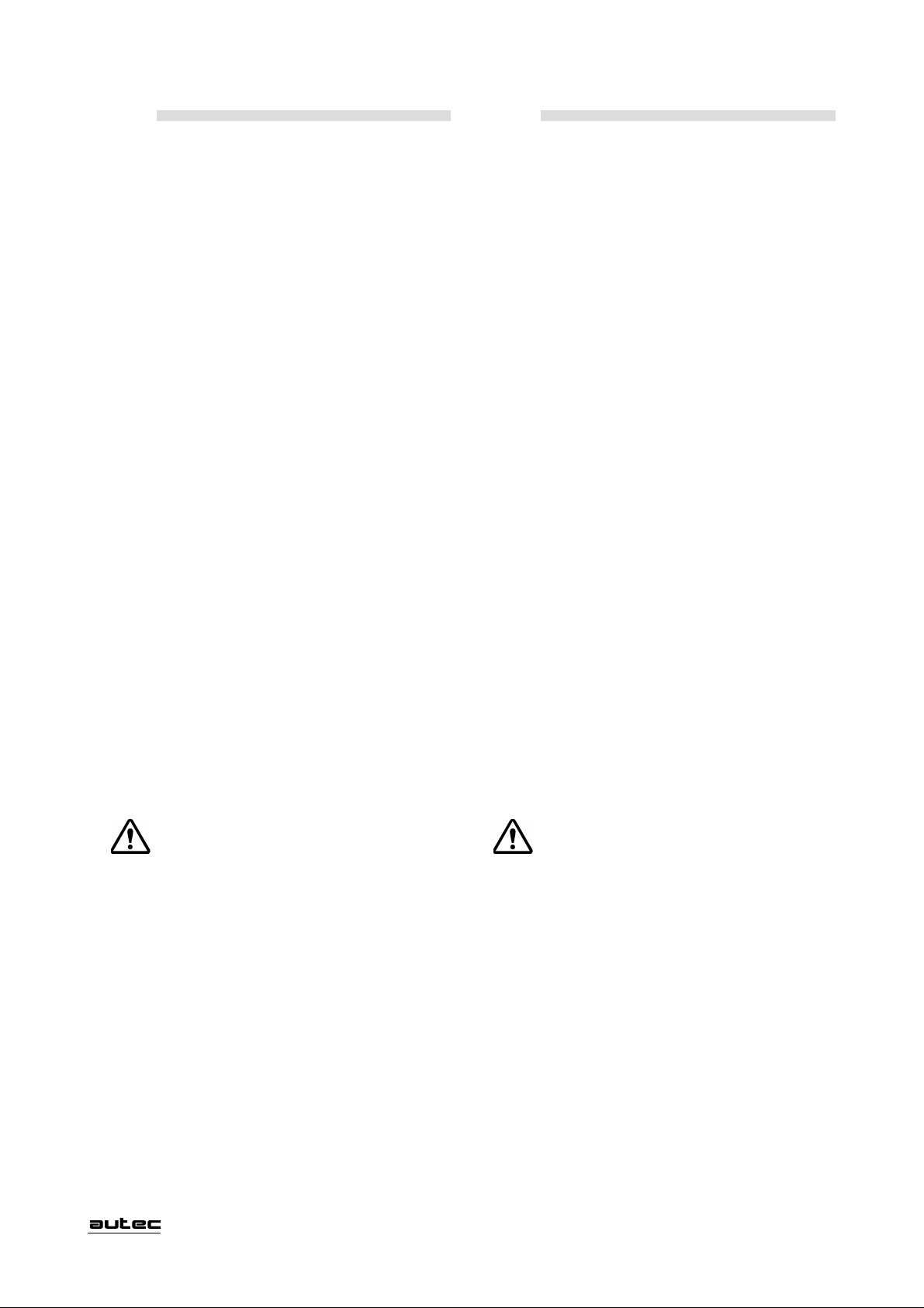
Radio remote controls of the C26-PRO series are
equipped with circuits to protect against unintended
movement from stillstand, this protection is only effective
if the manoeuvres common is wired in series with the
"SAFETY" command contact (set of contacts which
assume N.C. status as each movement command is
transmitted).
Should different common returns (max 5) be required for
the movements, it is sufficient to use the relay cards with
"additional SAFETY contact" (1 available for each card).
Examples of SAFETY circuit wiring.
Example 1
Receiver Empfänger
Vac
T. L .
T. L .
0 Vac
START
STOP
F2 Protected
STOP Relay
SAFETY
des Empfängers in Serie mit dem Kontakt der
“SAFETY”-Steuerung geschaltet ist (Reihe von Kontakten,
die mit jedem übertragenen Befehl in den Normalzustand
“geschlossen” übergehen).
Sollten für die Bewegungen mehrere verschiedene (max.
5) gemeinsame Kontakte erforderlich sein, können die
Relais-Karten mit dem “zusätzlichen SAFETY-Kontakt”
(verfügbar einer pro Karte ) verwendet werden.
Nachfolgend einige Verkabelungsbeispiele für die
Sicherheitskontrolle der Steuerbefehle.
Beispiel 1
To selection controls
common
Zum gemeinsamen Kontakt
der Wahlschalter
F3 Protected
SAFETY Relay
To manoeuvre
controls common
Zum gemeinsamen Kontakt
der Schaltungen
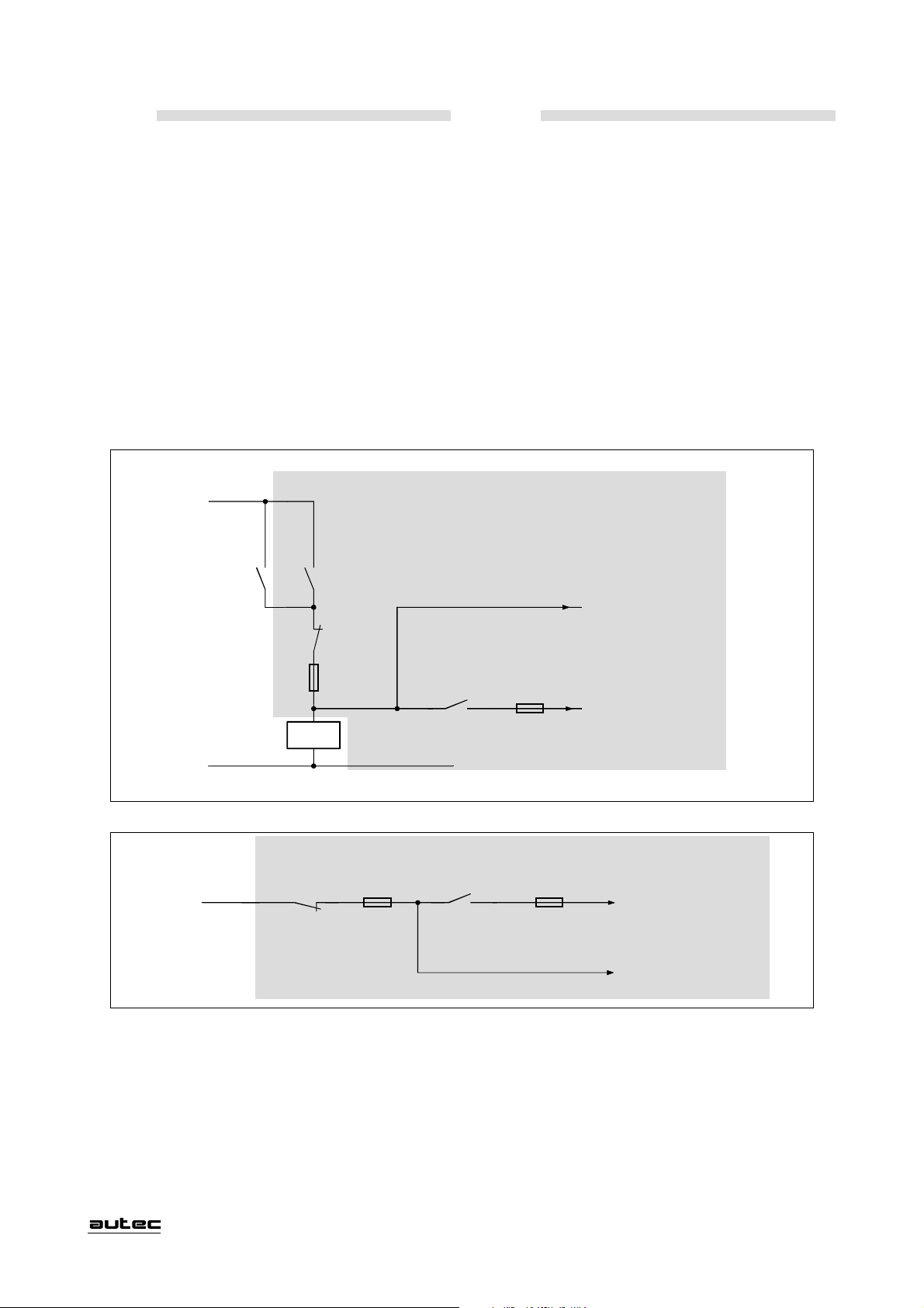
Example 2
Receiver
F2 Protected
STOP Relay
+24 Vdc
STOP
As can be seen from wiring examples above, the contact
of the SAFETY relay must be interposed in the power
supply to the manoeuvre common. The selection controls
common must not be wired in series with the SAFETY
contact.
Testing
The system must always be tested after installation. In
particular, it is essential to check that the main line
contactor of the machine opens on pressing the Stop button
LIPRO0U1
Beispiel 2
Empfänger
SAFETY
F3 Protected
SAFETY Relay
To manoeuvre
controls common
Zum gemeinsamen Kontakt
der Schaltungen
To selection controls
common
Zum gemeinsamen Kontakt
der Wahlschalter
Zwischen Spannungsversorgung und gemeinsamen
Betriebskontakt ist der Kontakt des SAFETY-Relais zu schalten.
Der gemeinsame Kontakt der Wahlschalter muß nicht in Serie
mit dem SAFETY-Kontakt verkabelt werden
Kontrollen und Prüfungen
Am Ende der Montage ist es notwendig, den Anschluß und
die Funktion der sicherheitsrelevanten Ausgänge des
Empfängers zu kontrollieren.
Es ist zu prüfen, ob mit dem Drücken des STOP-Tasters
- 7 -
Page 13

FRANÇAIS ITALIANO
Les radiocommandes de la série C26-PRO sont munies
de circuits de protection contre les mouvements
intempestifs de la position de repos, cette protection est
efficace si le commun des manoeuvres sur le récepteur
est câblé en série au contact de la commande "SAFETY"
(série de contacts qui se mettent en condition de N.F. à
chaque commande de mouvement transmise).
Si les manoeuvres de mouvement exigent des communs
différents (5 maximum), il suffira d'utiliser les cartes
relais avec "contact additionnel de SAFETY" (1 pour
chaque carte).
Voici quelques exemples de câblage du circuit
SAFETY.
Exemple 1
Recepteur Unità Ricevente
Vac
T. L .
T. L .
START
STOP
F2 Protected
STOP Relay
SAFETY
I radiocomandi della serie C26-PRO sono dotati di circuiti di protezione contro i movimenti involontari dalla
posizione di riposo, tale protezione è efficace se nell'Unità Ricevente il comune delle manovre è cablato in serie
al contatto del comando "SAFETY" (insieme di contatti
che si portano in condizione N.C. in corrispondenza di
ogni comando di movimento trasmesso).
In caso siano necessari comuni diversi (max 5) per le
manovre di movimento, è sufficiente utilizzare le schede
relè con "contatto aggiuntivo di SAFETY" (disponibile 1
per ogni scheda).
Sono riportati di seguito alcuni esempi relativi al
cablaggio del circuito SAFETY.
Esempio 1
Au commun des
commandes de sélection
Al comune
comandi di selezione
F3 Protected
SAFETY Relay
Au commun
des manoeuvres
Al comune
comandi manovre
0 Vac
Exemple 2
Recepteur
F2 Protected
STOP Relay
+24 Vdc
STOP
Ainsi qu'on peut le constater, l'alimentation doit être reliée au
commun des manoeuvres en interposant le contact du relais de
SAFETY. Le commun des commandes de sélection ne doit
pas être câblé en série au contact de SAFETY.
Vérifications et essais
Au terme de l'installation, il faut toujours procéder à
l'essai en vérifiant notamment l'ouverture du télérupteur
principal du circuit d'alimentation de la machine à la pression
du poussoir de Stop de la radiocommande. L'ouverture du
Esempio 2
Unità Ricevente
SAFETY
F3 Protected
SAFETY Relay
Au commun
des manoeuvres
Al comune
comandi manovre
Au commun des
commandes de sélection
Al comune
comandi di selezione
Come si può notare l'alimentazione deve essere portata
al comune delle manovre interponendo il contatto del relay
di SAFETY. Il comune dei comandi di selezione non deve
essere cablato in serie al contatto di SAFETY.
Verifiche e collaudi
Alla fine dell'installazione è sempre necessario effettuare il collaudo verificando in special modo l'apertura del
teleruttore principale di linea della macchina alla pressione del pulsante di Stop del Radiocomando. L'apertura
- 7 -
LIPRO0U1
Page 14

ENGLISH DEUTSCH
of the Radio remote control. The opening of this contactor
must disconnect the power supply to the entire machine and
return it to a condition of maximum safety.
It is also important to check that safety circuit functions
correctly. The simplest way to do this is to remove fuse F3
from the Receiver motherboard and then check that no
manoeuvres can be performed in this condition. Replace the
fuse after this test and check that the system functions
correctly.
To facilitate wiring, the arrangement of the controls on
the transmitter and the corresponding outputs on the
Receiver boards are shown on the technical data sheet
of the Radio remote control.
Note: The installer other than verifying and testing as
previously described, has to fill up the "technical data sheet",
take note of the wiring, put the date of installation sign it and
eventually put its stamp.
In case the "technical data sheet" would be needed for other
uses, always leave a copy together with the user’s manual.
6.0 OPERATING INSTRUCTIONS
6.1 BATTERY
am Sender das Hauptschütz der Maschine abfällt, und damit
die Maschine von der Versorgunsspannung getrennt wird.
Weiter ist zu prüfen, ob der Ausgang des "SAFETY"-Relais
korrekt verkabelt ist. Die einfachste Art ist, die Sicherung
"F3" herauszunehmen und die Anlage einzuschalten. Es darf
nicht möglich sein, eine sicherheitsrelevante Bewegung
auszuführen.
In der Anlage befindet sich eine Zeichnung auf der alle
Steuerbefehle des Senders eindeutig den Ausgängen des
Empfängers zugeordnet sind.
Hinweis: Zusätzlich zur Durchführung der beschriebenen
Kontrollen und Prüfungen muß das Installationspersonal das
Datenblatt vollständig ausfüllen und alle Punkte überprüfen,
dabei die vorgenommene Verkabelung und das Datum der
Inbetriebnahme der Anlage angeben sowie Stempel und
Unterschrift anbringen. Auch wenn das Datenblatt zu
verwaltungstechnischen Zwecken benötigt wird, muß dem
Bedienungshandbuch stets eine Kopie desselben beiliegen.
6.0 ANGABEN UND BEDIENUNGSANWEISUNGEN
6. 1 AKKUS
The Radio remote control is supplied with 2 batteries to
ensure continuity of service (one battery in use and one
recharging).
The Transmitter battery must only be recharged using the
battery charger supplied with the Radio remote control.
Incorrect use can significantly reduce
battery life, for example:
- use outside the operating temperature
range (-20 to +70)ºC.
- recharging performed outside the temperature range
(+5 to +35)ºC.
- prolonged non-use
- exposure to heat sources
- storage in damp environments
- storage at temperatures outside the following ranges
(recommended (0 to 45ºC )
(permitted -45°C to +50°C ).
The number of charging cycles can also effect the service
life of the battery, we therefore recommend that the
battery is always used until fully discharged.
The battery charge status is shown by the indicator lights
on the Transmitter.
If a battery runs down after only short length of time in
operation, this is an indication that the battery is near the
end of its service life and should be renewed.
Do not dispose of used batteries in
ordinary urban waste bins. Always use
the appropriate collection bins.
Mit der Funkfernsteuerung werden immer zwei Akkus für
den Sender mitgeliefert, um die Fortsetzung der Arbeit bei
leerem Akku zu garantieren (ein Akku in Funktion, einer zum
Aufladen).
Das Aufladen der Akkus darf nur mit dem Akkuladegerät
erfolgen, das mit der Funkfernsteuerung geliefert wird.
Eine unsachgemäße Verwendung kann die
Lebensdauer der Akkus erheblich verkürzen,
z. B.:
- Verwendung außerhalb der Arbeitstemperatur
(-20 ÷ +70)° C
- Aufladen außerhalb der Arbeitstemperatur des
Akkuladegeräts (+5 ÷ +35)° C
- Längeres Nichtbenutzen
- Betrieb und Lagerung nahe von Wärmequellen
- Lagerung in feuchter Umgebung
- Lagerung außerhalb der Normaltemperatur
(empfohlen 0 bis +45°C)
(erlaubt -45°C bis + 50°C).
Auch hat die Anzahl der Ladezyklen Einfluß auf die
Lebensdauer der Akkus.
Deshalb wird empfohlen, diese immer bis zur
vollständigen Entladung zu benutzen.
Der Ladezustand der Akkus wird am Sender durch zwei
Kontrollampen angezeigt.
Wird ein entladener Akku angezeigt, so ist dieser umgehend
zu ersetzen.
Es ist verboten, Akkus mit dem Hausmüll
oder über einen öffentlichen
Abfallbehälter zu entsorgen. Die Akkus
müssen in eigenen Behältern gesammelt
werden.
LIPRO0U1
- 8 -
Page 15

FRANÇAIS ITALIANO
télérupteur doit couper l'alimentation en énergie électrique à
toute la machine en la mettant en condition de sécurité totale.
Mais il est tout aussi important de vérifier le circuit de
sécurité. Pour cela, il suffit d'enlever le fusible F3, implanté
sur la carte principale du récepteur, et vérifier qu'aucune
manoeuvre, considérée de sécurité, ne puisse s'effectuer
dans ces conditions. Après quoi, remettre en place le fusible
F3 et s'assurer du bon fonctionnement.
À noter que sur la fiche technique de la radiocommande est
représentée la disposition des commandes sur l'émetteur et
la correspondance des sorties sur les cartes du récepteur
de manière à faciliter le câblage.
N.B. En plus des contrôles et des essais mentionnés cidessus, l'installateur doit remplir et/ou vérifier dans toutes
ses parties la "fiche technique" qui contient la connexion
électrique effectuée; il doit aussi indiquer la date de mis en
service de la machine et apposer son cachet avec sa
signature. Même en cas d'utilisation de la fiche technique
pour pratiques administratives, une copie de la même doit
être toujours conservée jointe au manuel de l'utilisateur.
6.0 FONCTIONNEMENT
6.1 BATTERIE
del teleruttore deve togliere l'alimentazione a tutta la
macchina portandola in condizioni di massima sicurezza.
È altresì importante verificare il circuito di sicurezza.
Un modo semplice è quello di togliere il fusibile F3,
alloggiato sulla scheda principale della Unità Ricevente,
e verificare che in queste condizione nessuna manovra,
considerata di sicurezza, possa essere effettuata, alla fine
inserire nuovamente il fusibile F3 e assicurarsi del corretto funzionamento.
Per facilitare il cablaggio, nella scheda tecnica del Radiocomando è riportata la disposizione dei comandi sull'Unità Trasmittente e la corrispondenza delle uscite sulle
schede dell'Unità Ricevente.
N.B. L'istallatore oltre alle verifiche e collaudi precedentemente descritti, deve compilare e/o verificare in tutte le sue
parti la "scheda tecnica" riportante il cablaggio effettuato,
ponendo inoltre la data di messa in funzione dell'impianto con
timbro e firma. Anche in caso di utilizzo della "scheda
tecnica" per pratiche amministrative, una sua copia deve
sempre rimanere allegata al manuale d'uso.
6.0 INDICAZIONI ED ISTRUZIONI DI IMPIEGO
6.1 BATTERIA
La radiocommande est toujours livrée avec 2 batteries
pour garantir la continuité de travail (une batterie en
service et une en recharge).
Les batteries pour l'alimentation de l'émetteur doivent être
rechargées uniquement par le chargeur de batterie fourni
avec la radiocommande.
Une utilisation incorrecte peut rapidement
réduire la durée des batteries, comme par
exemple :
- l'utilisation hors de la gamme de température
(-20 ÷ +70)ºC.
- la recharge hors de la gamme de température
(+5 ÷ +35)ºC.
- l'inutilisation prolongée
- l'exposition à des sources de chaleur
- le stockage dans des locaux humides
- le stockage hors de la gamme de température
(préconisée (0 ÷ 45ºC ) ( admise -45°C ÷ +50°C ).
Même le nombre des recharges influence la durée des
batteries, il est donc recommandé de toujours les
utiliser jusqu'à leur décharge complète.
L'état de charge de la batterie est signalé sur l'émetteur
par des témoins adéquats.
Il faut procéder au remplacement des batteries par des
neuves lorsque l'autonomie de fonctionnement de la
radiocommande tend à diminuer sensiblement.
Con il Radiocomando vengono fornite sempre 2 batterie,
al fine di assicurare la continuità di lavoro (una batte-
ria in funzione ed una in ricarica).
La batteria per l'alimentazione dell'Unità Trasmittente
deve essere ricaricata esclusivamente con apposito
caricabatterie fornito con il Radiocomando.
Un cattivo uso può rapidamente ridurre la
durata della batteria come ad esempio:
- l'utilizzo fuori dal range della temperatura di
lavoro (-20 ÷ +70)ºC.
- la ricarica fuori dal range della temperatura (+5 ÷
+35)ºC.
- l'inutilizzo prolungato
- l'esposizione a fonti di calore
- l'immagazzinaggio in ambienti umidi
- l'immagazzinaggio a temperatura fuori dal range
(raccomandata da 0 a 45ºC)
(permessa da -45°C a +50°C).
Anche il numero dei cicli di ricarica influenza la durata
della batteria, pertanto si consiglia di usarla sempre
fino a scarica completa.
Lo stato di carica della batteria è segnalato sull'Unità
Trasmittente dalle apposite spie. Quando l'autonomia di
funzionamento del radiocomando tende a ridursi sensibilmente, è indispensabile procedere alla sostituzione della
batteria con una nuova.
Pour l'élimination des batteries, utiliser
exclusivement les conteneurs spéciaux
prévus pour la collecte sélective des
batteries.
È vietato gettare le batterie nei raccoglitori dei rifiuti urbani. Lo smaltimento
delle batterie usate deve essere fatto tramite gli appositi raccoglitori.
- 8 -
LIPRO0U1
Page 16

ENGLISH DEUTSCH
6. 2 TRANSMITTER
Transmitter
C26-PRO KD
Transmitter
C26-PRO MD
C26-PRO MA
6.2 SENDER
Sender
C26-PRO KD
d
c
b
d
c
g
h
g
h
e
f
Sender
C26-PRO MD
C26-PRO MA
b
a
c
d
f
e
Transmitter
C26-PRO LD
a
d
c
a) joystick controls
b) pushbutton controls (or selectors)
c) red indicator light
d) green indicator light
e) stop button
f) starting key
g) battery
h) identification plate (in battery housing)
c
d
h
h
g
Sender
C26-PRO LD
e
b
g
f
h
g
a) Bedienhebel
b) Bedientasten
c) Rote Kontrollampe
d) Grüne Kontrollampe
e) STOP-Taster
f) Schlüsselschalter
g) Akku
h) Typenschild (unter dem Akku)
LIPRO0U1
- 9 -
Page 17

FRANÇAIS ITALIANO
6. 2 ÉMETTEUR
Émetteur
C26-PRO KD
Émetteur
C26-PRO MD
C26-PRO MA
6.2 UNITÀ TRASMITTENTE
Unità Trasmittente
C26-PRO KD
d
c
b
d
c
g
h
g
h
e
f
Unità Trasmittente
C26-PRO MD
C26-PRO MA
b
a
c
d
f
c
d
e
Émetteur
C26-PRO LD
h
g
e
a
d
c
a) actionneurs de manoeuvre à levier
b) actionneurs de manoeuvre à poussoir (ou sélecteur)
c) voyant de signalisation rouge
d) voyant de signalisation vert
e) poussoir de stop
f) clé d'allumage
g) batterie
h) plaquette d'identification (dans compartiment batterie)
h
g
Unità Trasmittente
C26-PRO LD
b
f
h
g
a) attuatori di manovra a leva
b) attuatori di manovra a pulsante (o selettore)
c) spia di segnalazione rossa
d) spia di segnalazione verde
e) pulsante di stop
f) chiave di accensione
g) batteria
h) targhetta di identificazione (nel vano porta batteria)
- 9 -
LIPRO0U1
Page 18

ENGLISH DEUTSCH
Power on
Check that the starting key
is in position “O”, insert the
battery in its housing without
force. Check that the stop
button has not been pressed
and that none of the joystick
or pushbutton controls have
been operated.
Turn the starting key to “I” and then to “START”, and
release it when the green light starts to flash.
If when the starting key is turned to "START", the red
light illuminates steadily and at the same time, the
Transmitter emits an acoustic alarm signal, this means
that the stop button or one of the controls has been
operated.
NB. The unit will only start if the battery is
sufficiently charged and all the controls are in the
zero (neutral) position .
Controls
Operate the controls relative to the manoeuvres to be
performed.
Stop
Press the stop button; the
machine will stop
immediately; the Transmitter
will switch off automatically
after a few seconds.
Turn the stop button to
restore operating conditions.
Power off
Turn the starting key to position “O”, remove it from
the keyswitch and store in a safe place.
Einschalten
Stellen Sie sicher, daß der
Schlüsselschalter zum
Einschalten auf Position "O"
steht, und setzen Sie den Akku
in die dafür vorgesehene
Aufnahme ohne dabei Druck
auszuüben. Prüfen Sie, daß der
STOP-Taster nicht gedrückt und keiner der Bedienhebel
betätigt ist. Drehen Sie den Schlüsselschalter in Position "I"
und anschließend auf START. Er kann losgelassen werden,
sobald die grüne Kontrollampe aufleuchtet.
Wenn beim Einschalten mit dem Schlüsselschalter in Stellung
"START" die rote Kontrollampe kontinuierlich aufleuchtet und
gleichzeitig der Sender ein akustisches Signal abgibt, heißt das,
daß der STOP-Taster noch gedrückt und verriegelt oder einer
der Bedienungshebel betätigt ist.
N.B.: Das Einschalten ist nur möglich, wenn der Akku
ausreichend geladen ist, und wenn sich alle
Befehlsgeber (Bedienhebel bzw. Bedientasten) in
Stellung "0" befinden, d. h. nicht eingeschaltet sind.
Befehle
Betätigen Sie die für die Arbeit erforderlichen Bedienhebel
bzw. drücken oder drehen Sie die erforderlichen Taster
oder Schalter.
Stop
Drücken Sie den STOP-Taster.
Die Maschine wird unmittelbar
danach abgeschaltet. Der
Sender schaltet sich
automatisch nach wenigen
Augenblicken aus.
Der STOP-Taster muß entriegelt werden, bevor sich der
Sender wieder einschalten läßt.
Automatic power down
After a few minutes of non-use, the Transmitter will
switch off automatically, and return the machine to a
condition of safety (stop relay contact open).
Automatic power down will also occur if the battery is
not sufficiently charged.
Battery charge status indicator
When the battery is approximately 90% discharged, the
green light will start flashing at a faster rate to inform
the operator that the battery requires recharging.
If the operator continues to use the Radio Control,
approximately 3 minutes before the battery is fully
discharged, the red light will start flashing and an
acoustic alarm will sound.
In this situation, the operator must return the machine to
a condition of safety (by pressing the stop button),
switch off the Transmitter, and recharge the battery or
fit a fully charged battery.
LIPRO0U1
Ausschalten
Drehen Sie den Schlüsselschalter in Stellung "O". Nehmen Sie
den Schlüssel heraus und bewahren Sie ihn an einem sicheren
Platz auf.
Automatische Abschaltung
Wird der Sender länger als ca.3 Minuten nicht benutzt, schaltet
sich dieser automatisch ab und die Maschine wird ausgeschaltet
(Kontakt des STOP-Relais öffnet).
Die automatische Abschaltung erfolgt auch, wenn der Akku
nicht ausreichend geladen ist.
Anzeige des Ladezustandes des Akkus
Wenn der Akku ca.90% seiner Ladung aufgebraucht hat,
erhöht sich die Blinkgeschwindigkeit der grünen Kontrollampe
des Senders. Wenn die Funkfernsteuerung weiter benutzt wird,
beginnt die rote Kontrollampe zu blinken. Gleichzeitig ertönt
ein akustisches Signal. Es verbleiben ca. 3 Minuten, um die
Maschine in einen sicheren Zustand zu bringen, den Sender
auszuschalten und den Akku zu laden oder zu tauschen.
- 10 -
Page 19

FRANÇAIS ITALIANO
Allumage
S'assurer que la clé
d'allumage est en position
“O”, mettre en place la batterie dans son compartiment
sans forcer. Vérifier que le
poussoir de Stop et
qu'aucun actionneur n'est
actionné.
Tourner la clé d'allumange en position “I” puis en
position “START” et la lâcher aussitôt que commence à
clignoter le voyant vert.
Au cas où, avec la clé d'allumage en position de
"START", le voyant rouge s'allume et l'émetteur émet
en même temps un signal sonore, cela signifie que le
poussoir de Stop ou un des actionneurs de commande
des manoeuvres est actionné.
N.B. L'allumage n'est possible que si la batterie est
suffisamment chargée et si tous les actionneurs des
manoeuvres sont en position zéro (débranchés).
Commandes
Actionner les actionneurs des manoeuvres que l'on veut
commander.
Arrêt
Enfoncer le poussoir de Stop;
la machine s'arrête
immédiatement; l'émetteur
s'éteint automatiquement après
un instant.Tourner le poussoir
de Stop pour le rétablissement
du fonctionnement normal.
Accensione
Accertarsi che la chiave di
accensione sia nella posizio-
ne “O”, inserire la batteria
nell’apposita sede senza forzare. Verificare che il pul-
sante di stop e nessuno degli attuatori sia azionato.
Girare la chiave di accensione in posizione “I” e successivamente in posizione “START” rilasciandola quando
la spia verde inizia a lampeggiare.
Qualora, con la chiave di accensione in posizione di
"START", si accendesse la spia rossa in modo continuo
e, contemporaneamente, l'Unità Trasmittente emettesse un
segnale acustico, significa che il pulsante di stop o uno
degli attuatori di comando delle manovre è azionato.
N.B. L' accensione avviene solo se la batteria è
sufficientemente carica e se tutti gli attuatori delle
manovre sono in posizione zero (disinseriti).
Comandi
Azionare gli attuatori relativi alle manovre che si intendono comandare.
Arresto
Azionare il pulsante di stop;
la macchina si arresta immediatamente; l'Unità Trasmittente si spegne automaticamente dopo qualche istante.
Ruotare il pulsante di stop
per ripristinare la condizione
di funzionamento.
Extinction
Tourner la clé d'allumage en position “O” et la retirer
pour la ranger dans un endroit sûr.
Extinction automatique
Après quelques minutes d'inutilisation l'émetteur s'éteint,
en conduisant la machine en état de sécurité (contact du
relais de stop ouvert).
L'extinction automatique intervient même quand l'état de
charge de la batterie est insuffisant.
Visualisation de l'état de charge de la batterie
À 90% environ de l'état de décharge de la batterie, le
rythme du clignotement du voyant vert augmente pour
signaler la nécessité de procéder à la recharge de la bat-
terie.
Au cas où l'on continue à utiliser la radiocommande, 3
minutes environ avant la décharge totale de la batterie,
le voyant rouge commence à clignoter et une alarme so-
nore retentit en même temps.
Dans cette situation, mettre la machine en état de
sécurité (en enfonçant le poussoir de stop), éteindre
l'émetteur et procéder à la recharge de la batterie ou
bien la remplacer par une autre déjà rechargée.
Spegnimento
Girare la chiave di accensione in posizione “O” estrarla dalla sede e riporla in luogo sicuro.
Spegnimento automatico
Dopo qualche minuto di inutilizzo l'Unità Trasmittente si
spegne, portando la macchina in stato di sicurezza (contatto del relè di stop aperto).
Lo spegnimento automatico interviene anche quando la
carica della batteria è insufficiente.
Visualizzazione stato di carica della batteria
Quando la batteria ha erogato circa il 90% della sua
carica, la spia verde aumenta la velocità di lampeggio
per preavvisare che occorre provvedere alla ricarica.
Se si continua ad utilizzare il Radiocomando, circa 3
minuti prima che la batteria esaurisca la sua carica, la
spia rossa inizia a lampeggiare e contemporaneamente
interviene un avvisatore acustico.
In presenza di questa situazione portare la macchina in
stato di sicurezza (azionando il pulsante di stop), spegnere l'Unità Trasmittente e mettere in ricarica la bat-
teria oppure sostituirla con una già carica.
- 10 -
LIPRO0U1
Page 20

ENGLISH DEUTSCH
Transmitter indicator lights:
Operation
Slow
flashing
Fast
flashing
Steadily lit on
power on*
Both lights
steadily lit
simultaneously*
* With acoustic alarm
6.3 RECEIVER
Green Red
Normal operation
1st low battery
charge warning
Frequency changed
Light
2nd low battery
charge warning
Control operated
during power on
Leuchtanzeigen am Sender:
Funktion
Blinken
langsam
Blinken
schnell
Dauerleuchten*
beim
Einschalten
Dauerleuchten*
beider
Kontrollampen
* Mit akustischem Signal
6.3 EMPFÄNGER
Grün Rot
Normale
Funktion
1. Anzeige
für Akku-
entladung
Kontrollampe
2. Anzeige
für Akkuentladung
Steuerbefehl
aktiviert
Frequenzwechsel
erfolgt
a
b
a) key for opening the casing
b) identification plate
c) connection plug
d) POWER SUPPLY light
e) SYSTEM ENABLED light
Receiver indicator lights:
Lights POWER SUPPLY
Illuminates to indicate that the unit receiving power.
Lights SYSTEM ENABLED
Illuminates to indicate that radioelectrical connection has
been established between the Transmitter and Receiver.
d
e
c
a) Schloß zum Öffnen des Gehäuses
b) Typenschild
c) Verbindungsstecker
d) Kontrollampe POWER SUPPLY
e) Kontrollampe SYSTEM ENABLED
Anzeigen im Empfänger
Kontrollampe POWER SUPPLY
Versorgungsspannung liegt an.
Kontrollampe SYSTEM ENABLED
Leuchtet bei Verbindung zwischen Sender und Empfänger.
LIPRO0U1
- 11 -
Page 21

FRANÇAIS ITALIANO
Signalisations de l'émetteur:
Fonctionnement
Vert Rouge
Clignotement
lent
Clignotement
rapide
Allumage *
permanent
à mise sous tension
Allumage *
permanent et
simultané
des deux voyants
Fonctionnement
normal
1ère signalisation
de batterie
déchargée
Changement de fréquence
* Accompagnée d'un signal sonore
6. 3 RÉCEPTEUR
Voyant
2ème signalisation
de batterie
déchargée
Commande
enclenchée
pendant
l'allumage
advenu
Segnalazioni dell'Unità Trasmittente:
Funzionamento
Spia
Verde Rossa
Lampeggio
lento
Lampeggio
veloce
Funzionamento
normale
Segnalazione 1°
avviso batteria
scarica
Segnalazione 2°
avviso batteria
Luce* continua
all'accensione
Luce* continua
e simultanea di
entrambe le spie
Avvenuto
cambio di frequenza
inserito durante
* Con segnale acustico
6.3 UNITÀ RICEVENTE
scarica
Comando
accensione
a
b
a) clé d'ouverture du coffret
b) plaquette d'identification
c) fiche
d) témoin POWER SUPPLY (d'alimentation)
e) témoin SYSTEM ENABLED (de validation liason système)
Signalisations du récepteur :
Témoin POWER SUPPLY
Indique la présence d'alimentation si allumé.
Témoin SYSTEM ENABLED
Indique que la liaison radioélectrique entre l'émetteur et
le récepteur est active si allumé.
d
e
c
a) chiave apertura cassetta
b) targhetta di identificazione
c) spina di collegamento
d) spia POWER SUPPLY
e) spia SYSTEM ENABLED
Segnalazioni dell'Unità Ricevente:
Spia POWER SUPPLY
Accesa indica presenza di alimentazione.
Spia SYSTEM ENABLED
Accesa indica l'avvenuto collegamento radioelettrico fra
Unità Trasmittente e Unità Ricevente.
- 11 -
LIPRO0U1
Page 22

ENGLISH DEUTSCH
Indicator lights and protections located inside the
Receiver:
On motherboard
VS
F5
VE
F4
Light POWER SUPPLY
Illuminates to indicate that the unit is receiving power.
Light VE *
Illuminates to indicate the presence of the supply voltage
for the electronic circuitry.
Light VS *
Illuminates to indicate the presence of relay pilot voltage.
* AC versions only
Anzeigen und Sicherungen im Empfänger
Grundkarte im Empfänger
F3
F2
F1
POWER SUPP LY
Kontrollampe POWER SUPPLY
Versorgungsspannung liegt an.
Kontrollampe VE *
Leuchtet bei vorhandener Spannung im Stromkreis.
Kontrollampe VS *
Leuchtet bei vorhandener Spannung in der Relaissteuerung.
* Nur für AC-Version
On relay board
Lights Command
Illuminate to indicate that
the adjacent relay is
energized.
Other indicator lights are
documented separately on
Lights Command
the corresponding
identification plate.
Electrical protections - Fuses located inside the
Receiver:
Fuse Protection
F1 Power input.
F2 Stop contact.
F3 Safety contact.
F4 * Electronic circuitry supply voltage VE.
F5 * Relay pilot voltage VS.
* AC version only
Relaiskarten
Kontrollampen Befehl
Leuchtet, wenn das
anliegende Relais
angesteuert ist.
Andere Kontrollampen sind
einzeln auf den
entsprechenden
Schildern kommentiert.
Kontrollampen Befehl
Elektr. Sicherungen im Empfänger
Sicherung Schutz
F1 Power Eingang
F2 STOP-Relais.
F3 SAFETY-Relais.
F4 * Kreislauf VE.
F5 * Relais VS.
* Nur für AC-Version
LIPRO0U1
- 12 -
Page 23

FRANÇAIS ITALIANO
Signalisations et protections intégrées au récepteur :
Sur carte de base
VS
F5
VE
F4
Témoin POWER SUPPLY
Indique la présence d'alimentation si allumée.
Témoin VE *
Indique la présence de tension d'alimentation sur le
circuit électronique si allumé.
Segnalazioni e protezioni poste all'interno dell'Unità Ricevente:
Su scheda base
F3
F2
F1
POWER SUPP LY
Spia POWER SUPPLY
Accesa indica presenza di alimentazione.
Spia VE *
Accesa indica presenza tensione alimentazione circuiteria
elettronica.
Témoin VS *
Indique la présence de tension de pilotage du relais si allumé.
* Seule version à c.a.
Sur cartes relais
Témoins Commande
Indiquent l'activation du
relais adjacent si allumés
Voir plaques respectives
pour les autres témoins
(documentation à part).
Témoins de commande
Protections électriques - Fusibles de protection
intégrés au récepteur :
Fusible Protection
F1 Entrée Power (Alimentation).
F2 Contact de Stop.
F3 Contact de Safety.
F4 * Tension d'alimentation sur le circuit électr. VE.
F5 * Tension de pilotage du relais VS.
Spia VS *
Accesa indica presenza tensione pilotaggio relè.
* Solo per versione in AC
Su schede relè
Spie Comando
Accese indicano l'attivazione relè adiacente.
Altre spie vengono documentate a parte con apposita targhetta
Spie di comando
Protezioni elettriche - Fusibili di protezione posti
all'interno dell'Unità Ricevente:
Fusibile Protezione
F1 Ingresso Power.
F2 Contatto di Stop.
F3 Contatto di Safety.
F4 * Tensione alimentazione circuit.elett. VE.
F5 * Tensione pilotaggio relè VS.
* Seule version à c.a.
* Solo per versione in AC
- 12 -
LIPRO0U1
Page 24

ENGLISH DEUTSCH
6.4 BATTERY CHARGER
RECHARGING THE BATTERY
Remove the battery from the
Transmitter and insert in the
battery charger.
The "ON CHARGING" light will illuminate to indicate
that the battery is being charged. Once the battery is
fully charged, the "END OF CHARGE" light will
illuminate. Battery charging should be performed at an
ambient temperature within the range +5°C to +35°C.
In the event of a power failure, once the power is
restored recharging will recommence from the start
of the cycle.
7.0 SELECTING THE OPERATING
FREQUENCY
The Radio remote control is programmed by the
manufacturer for Automatic Scanning of Available
Frequencies; this allows the operator to change the
operating Frequency without having to make any
adjustments inside the Transmitter or Receiver.
The frequencies scanned are always within the
groups of frequencies permitted by the national
standards applicable at the time the product is
marketed.
6.4 AKKULADEGERÄT
LADEN DER AKKUS
Nehmen Sie den Akku aus der
Aufnahme des Senders und setzen
Sie ihn in die Aufnahme des
Akkuladegerätes.
Der Ladevorgang wird dann durch die Kontrollampe "ON
CHARGING" angezeigt. Eine vollständige Ladung dauert ca.
8 - 10 Stunden. Das Ende des Ladevorgangs wird von der
Kontrollampe "END OF CHARGE" angezeigt. Der
Ladevorgang darf nur bei einer Temperatur von + 5°C bis +
35°C erfolgen.
N.B.: Wird während des Ladevorgangs die
Versorgungsspannung des Akkuladegerätes aus- und
wieder eingeschaltet, beginnt der Ladevorgang von
vorne.
7. 0 ARBEITSFREQUENZEN
Die Funkfernsteuerung ist mit einem Verfahren zur
automatischen Abtastung der verfügbaren Frequenzen
ausgestattet. Standardmäßig ist vom Hersteller die
automatische Abtastung eingestellt.
Die verfügbaren Frequenzen und das Frequenzband sind so
gewählt worden, daß die zur Zeit dieser Ausgabe gültigen
nationalen Normen und Gesetze eingehalten werden.
Automatic Scanning of Available Frequencies.
Power on the Transmitter, turn the starter key to
START and hold in this position. After 5-6 seconds, a
prolonged beep accompanied by simultaneous illumination
of the red and green lights will indicate that the
operating frequency has been changed.
After changing the frequency the system must be
restarted in the normal manner.
The operations of changing the preset
group of frequencies and manual
frequency setting must only be carried
out by qualified persons who must
scrupulously adhere to the instructions
given in the "Technical Service
Manual".
8.0 PREVENTIVE MAINTENANCE
The Radio remote control system does not require any
particular maintenance; however, a few simple measures
are necessary to ensure that the equipment is always in
good and safe working order.
The operator must ensure that the
Receiver is not powered while the
Transmitter is being serviced.
Automatischer Frequenzwechsel
Drehen Sie, wenn der Sender bereits eingeschaltet ist, den
Schlüsselschalter in die Position START und halten sie ihn in
dieser Stellung fest. Nach ca. 5 - 6 Sekunden leuchten die
grüne und die rote Kontrollampe auf und zusätzlich ertönt ein
akustisches Signal. Der Frequenzwechsel ist nun erfolgt.
Nach dem Frequenzwechsel muß das System auf die übliche
Art und Weise wieder gestartet werden.
Ein Wechsel der Übertragungsfrequenz,
automatisch oder manuell, darf nur von
qualifiziertem Personal durchgeführt
werden. Die Angaben im "Technischen
Service Handbuch" sind zu befolgen.
8. 0 PRÄVENTIVWARTUNG
Die Funkfernsteuerung benötigt keiner besonderen Wartung.
Trotzdem sind einige Punkte zu beachten, um die Anlage in
optimalem Zustand zu betreiben.
Wenn Arbeiten am Sender durchgeführt
werden, ist vorher sicherzustellen, daß der
Empfänger nicht an die Maschine
angeschlossen ist und mit Spannung
versorgt wird.
LIPRO0U1
- 13 -
Page 25

FRANÇAIS ITALIANO
6.4 CHARGEUR DE BATTERIE
RECHARCHE DE LA BATTERIE
Retirer la batterie de l'émetteur
et la mettre dans le chargeur
de batterie.
La charge en cours est signalée par l'allumage du témoin "ON
CHARGING" (EN CHARGE). La durée de charge est
d'environ de 8 à 10 heures. La fin de charge est indiquée par
l'allumage du témoin "END OF CHARGE" (FIN DE
CHARGE). La charge de la batterie doit se faire par une
température ambiante comprise entre +5°C et +35°C.
En cas de coupure de courant, la recharge reprend
dès le début.
7.0 SÉLECTION DE LA FRÉQUENCE
D'UTILISATION
La radiocommande est programmée par le constructeur
en mode Balayage automatique des fréquences
disponibles; cette solution technique permet de
déplacer la fréquence d'utilisation sans devoir intervenir dans l'émetteur ni dans le récepteur.
Les fréquences disponibles par balayage sont toujours
des fréquences agréées selon les normatives nationales
en vigueur au moment de la commercialisation du
produit.
6. 4 CARICABATTERIE
RICARICA DELLA BATTERIA
Togliere la batteria dall’Unità Trasmittente ed inserirla nell'apposita
sede del caricabatterie.
La ricarica in corso viene segnalata dall'accensione della
spia "ON CHARGING". Per una ricarica completa occorrono circa 8÷10 ore. La fine carica viene segnalata dall'accensione della spia "END OF CHARGE". La ricarica della
batteria deve avvenire con una temperatura ambiente compresa fra +5°C e +35°C.
In caso di mancanza di alimentazione la ricarica
riparte dall'inizio.
7.0 IMPOSTAZIONE FREQUENZA
DI LAVORO
Il Radiocomando viene programmato dal costruttore
nella modalità di Scansione Automatica delle Frequenze Disponibili, modalità che consente di spostare la
Frequenza di lavoro senza dover intervenire all'interno dell'Unità Trasmittente e Ricevente.
Le frequenze disponibili nella scansione appartengono sempre all'insieme delle frequenze ammesse
dalle normative nazionali in vigore al momento dell'emissione sul mercato.
Balayage automatique des fréquences disponibles.
Après la mise sous tension de l'émetteur, ramener la clé
d'allumage en position START. En maintenant cette
position, après 5 ou 6 secondes, un signal sonore
prolongé retentira, doublé de l'allumage simultané des
témoins rouge et vert, pour signaler le changement de
fréquence.
Après le changement de fréquence, il faut faire repartir
le système par un START.
La variation de la plage de fréquences
présélectionnées ou l'éventuelle
sélection manuelle de fréquence doit
être effectuée par un personnel habilité
à réaliser cette opération en suivant
scrupuleusement les instructions
contenues dans le "Manuel d'assistance
technique".
8. 0 ENTRETIEN PRÉVENTIF
Le système radio ne nécessite aucun entretien particulier.
Mais il faut respecter quelques petites règles
élémentaires pour travailler avec un équipement toujours
efficace et sûr.
Il incombe au responsable de
maintenance de s'assurer que le
récepteur n'est pas alimenté pendant les
opérations de contrôle de l'émetteur.
Scansione Automatica delle Frequenze Disponibili.
Dopo l'accensione dell'Unità Trasmittente, riportare la
chiave di accensione su START. Mantenendo tale po-
sizione, dopo 5-6 secondi, un prolungato biip accompagnato
dall'accensione contemporanea delle spie rossa e verde
indicherà l'avvenuto cambio di frequenza.
Dopo il cambio frequenza il sistema deve essere fatto
ripartire con una normale azione di START.
Il cambio di gruppo di frequenze preimpostate, o l'eventuale impostazione manuale di frequenza, può essere fatto
esclusivamente da personale qualificato,
che dovrà seguire scrupolosamente le
istruzioni riportate nel "Manuale Assistenza Tecnica".
8.0 MANUTENZIONE PREVENTIVA
Il sistema Radiocomando non necessita di particolari manutenzioni, tuttavia sono necessari alcuni accorgimenti per
lavorare con un’apparecchiatura sempre efficiente e sicura.
Il personale addetto dovrà accertarsi
che l'Unità Ricevente non sia alimenta-
ta durante le operazioni di controllo
dell'Unità Trasmittente.
- 13 -
LIPRO0U1
Page 26

ENGLISH DEUTSCH
Transmitter
Regularly clean all dust and other deposits from the unit
and check that the outer casing is not cracked or
damaged in any way.
Seals, gaskets and key covers should be soft and elastic.
The battery contacts must be clean and free of corrosion.
The unit must be stored in a clean, dry place.
Any damaged parts must be replaced exclusively by
personnel authorised by Autec.
Receiver
The Receiver does not require any maintenance.
9.0 INSTRUCTIONS TO FOLLOW IN CASE OF
SYSTEM FAILURE
Before contacting technical assistance service,
ensure that you have read and understood this
manual and that you have followed the instructions
correctly.
If the Transmitter is powered on but the machine
under control will not start:
1) Move closer to the Receiver and try to start the
machine again; if the machine now starts this means that
the operating frequency is subject to interference; perform
automatic scanning to select a new operating frequency.
2) Check that the multipole plug connecting the
machine to the Receiver is inserted correctly.
Sender
Staub und andere Verunreinigungen müssen entfernt
werden. Die Gehäuseteile dürfen nicht beschädigt sein oder
Risse aufweisen.
Die Dichtungen, Bälge und Tastenkappen müssen weich und
elastisch sein.
Die Kontakte der Akkus müssen sauber sein
Die Lagerung muß immer in sauberer Umgebung erfolgen
Beschädigte Teile dürfen nur von autorisiertem Personal der
Firma Autec ausgetauscht werden.
Empfänger
Der Empfänger benötigt keiner besonderen Wartung
9.0 STÖRUNGEN
Bevor man den Servicetechniker ruft, ist es ratsam,
dieses Handbuch nochmals zu lesen, um
Fehlbedienungen ausschließen zu können.
Der Sender ist eingeschaltet, aber die Maschine startet
nicht:
1) Nähern Sie sich dem Empfänger und starten Sie den
Sender erneut. Wenn sich die Anlage in geringer Entfernung
starten läßt, ist dies ein Zeichen dafür, daß die benutzte
Funkfrequenz gestört ist. Stellen Sie eine andere
Arbeitsfrequenz ein.
2) Kontrollieren Sie, ob der Mehrfachstecker der
Verkabelung zwischen Empfänger und Maschine korrekt
angesteckt ist.
3) Check that the problem concerns the Radio remote
control by connecting a direct cable control and then
check operation.
4) Qualified persons may open the Receiver unit
using the key provided (CAUTION: live parts) and check
by visual inspection only that the lights POWER, VE
*, VS * are on.
(* If present)
If one of the lights is out, disconnect the power supply
to the Receiver, and check the relative fuse. Replace if
necessary with a fuse of the same type.
For all other types of failure contact your
authorised Autec service centre.
LIPRO0U1
3) Falls vorhanden, probieren Sie aus, ob die
festverdrahtete Steuerung der Maschine funktioniert.
Funktioniert diese auch nicht, ist der Fehler in der Maschine
zu suchen.
4) Wenn die Fehlersuche von autorisiertem Personal
durchgeführt wird, kann mit dem passenden Schlüssel das
Empfängergehäuse geöffnet werden (Vorsicht, der
Empfänger steht unter Spannung!), um die Signallampen
POWER, VE*, VS* zu kontrollieren.
(* nur bei AC-Version vorhanden)
Leuchtet eine dieser Lampen nicht, trennen Sie den Empfänger
von der Maschine und kontrollieren Sie die Sicherungen des
Empfängers.
Sollte eine Sicherung defekt sein, tauschen Sie diese durch eine
gleich aus.
Läßt sich der Fehler durch die oben beschriebenen
Maßnahmen nicht beseitigen, ist es nur von der Firma
Autec autorisiertem Personal erlaubt, die notwendigen
Wartungsarbeiten durchzuführen.
- 14 -
Page 27

FRANÇAIS ITALIANO
Émetteur
Il faut régulièrement le débarrasser de tous dépôts de
poussière ou autres dépôts et effectuer le contrôle des
parties de l'enveloppe qui ne doivent pas être détériorées
ou fissurées.
Les joints, les soufflets et les protecteurs de touches
doivent être souples et élastiques.
Les contacts de la batterie doivent être propres.
Le stockage doit se faire dans des locaux propres et
secs.
Seul un personnel agréé par Autec est habilité à
remplacer les pièces éventuellement détériorées.
Récepteur
Le récepteur ne nécessite aucun entretien.
9.0 DÉPANNAGE
Avant toute demande d'intervention des techniciens
d'assistance, il convient de s'assurer d'avoir bien lu
et compris toutes les sections du présent manuel en
vérifiant d'avoir correctement suivi toutes
instructions qu'il contient.
Unità Trasmittente
E' opportuno regolarmente rimuovere la polvere e altri
accumuli ed eseguire il controllo delle parti componenti
l'involucro le quali non devono essere danneggiate o
mostrare crepe.
Le guarnizioni, i soffietti ed i cappucci dei tasti devono
essere morbidi ed elastici.
I contatti della batteria devono essere puliti.
L'immagazzinaggio deve essere fatto in ambiente pulito
ed asciutto.
Eventuali parti danneggiate possono essere sostituite
esclusivamente da personale autorizzato da Autec..
Unità Ricevente
L'Unità Ricevente non necessità di alcuna manutenzione.
9.0 ISTRUZIONI DA SEGUIRE IN CASO DI
GUASTO
Prima di far intervenire i tecnici dell'assistenza, é
opportuno aver letto e capito in tutte le sue parti
il presente manuale verificando di aver eseguito correttamente tutte le istruzioni riportate.
Si l'émetteur s'allume mais la machine ne part pas:
1) S'approcher du récepteur et répéter la tentative;
si la machine démarre à cette distance, cela signifie que
la fréquence est brouillée et il faut alors effectuer le
balayage automatique pour passer sur une nouvelle
fréquence d'utilisation.
2) Vérifier que la fiche multiple de câblage entre la
machine radiocommandée et le récepteur est
correctement implantée.
3) Vérifier que l'inconvénient est réellement causé
par la radiocommande en reliant le poste de commande
câblé et en contrôlant le bon fonctionnement.
4) Seul un personnel qualifié peut ouvrir le boîtier
du récepteur à l'aide de la clé appropriée, (attention à
la présence de tension) et vérifier visuellement
l'allumage des témoins de signalisation POWER, VE *,
VS *.
(* Si montés)
Si un des témoins est éteint, il faut couper le courant
au récepteur et vérifier l'état du fusible correspondant au
témoin éteint en le remplaçant éventuellement par un
neuf de même calibre.
Se l'Unità Trasmittente si accende ma la macchina
non si avvia:
1) Avvicinarsi all'Unità Ricevente e ripetere il ten-
tativo; se a distanza ravvicinata si riesce ad avviare la
macchina, allora la frequenza radio in uso è disturbata,
per cui occorre effettuare la scansione automatica e
passare quindi ad una nuova frequenza di lavoro.
2) Verificare che la spina multipla di cablaggio fra la
macchina radiocomandata e l'Unità Ricevente sia agganciata correttamente.
3) E' opportuno verificare se il problema interessa re-
almente il Radiocomando, collegando il posto di comando
a cavo e controllando il corretto funzionamento.
4) Se il personale è competente può aprire con l'ap-
posita chiave l'Unità Ricevente, (attenzione si è in pre-
senza di tensione) e verificare solo visivamente l'accen-
sione delle spie di segnalazione POWER, VE*, VS*.
(* Se presenti)
Se una delle spie è spenta, togliere l'alimentazione
dall'Unità Ricevente e verificare l'integrità del fusibile re-
lativo alla spia spenta, sostituendolo eventualmente con
uno avente le stesse caratteristiche.
L'intervention d'un personnel agréé par Autec est
nécessaire pour tous autres types de panne.
Tipi di guasto diversi richiedono l'intervento di personale autorizzato dall'Autec.
- 14 -
LIPRO0U1
Page 28
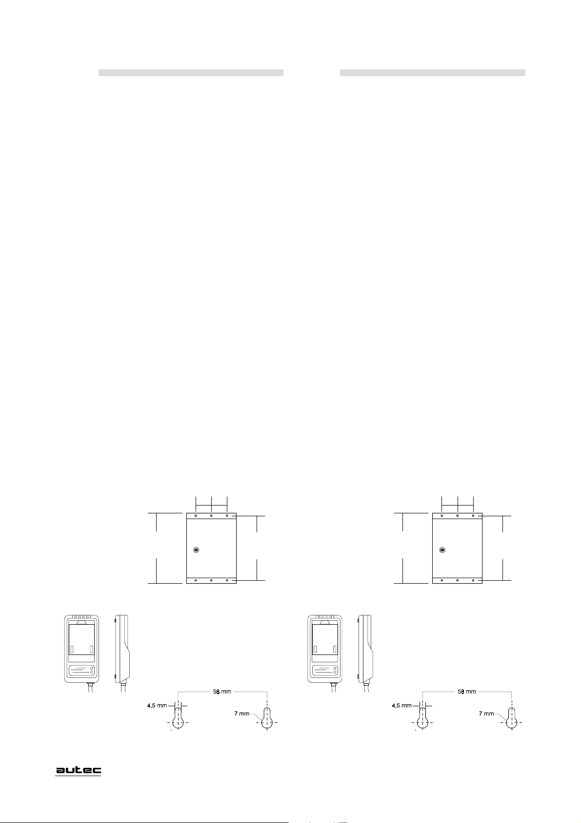
ENGLISH DEUTSCH
10.0 SERVICE
For all major servicing and repair operations (excluding
the cases described above), and for the replacement of
damaged parts, contact the Manufacturer.
11.0 WARRANTY
For warranty conditions refer to the "Certificate of
Guarantee".
List of electronic parts with 3 year warranty:
MRX...- RD97...- RI97...- CH97...- SBA97... .
MTX...-
12.0 DISPOSAL OF UNWANTED PRODUCTS
At the end of its working life, the Radio Remote Control
should be consigned to an authorised waste disposal
and reclamation service.
13.0 WEIGHTS AND DIMENSIONS
Transmitter Dimensions Weight
(with battery)
C26-PRO KD ( 94x305x51 ) mm 1 Kg
C26-PRO MD (173x160x263) mm 1,9 Kg
C26-PRO MA (173x160x263) mm 1,9 Kg
C26-PRO LD (200x385x284) mm 4,2 Kg
10.0 KUNDENDIENST
Wenn in seltenen Fällen die Funkfernsteuerung repariert
werden muß (ausgenommen die vorher beschriebenen
Handlungen), bzw. beschädigte Teile ersetzt werden müssen,
wenden Sie sich bitte ausschließlich an die Firma Autec.
11.0 GARANTIE
Die Garantiebestimmungen für die Funkfernsteuerung sind im
beiliegenden "Garantiezertifikat" festgelegt.
Liste der elektronischen Teile mit 3 Johren Garantie:
MTX...- MRX...- RD97...- RI97...- CH97...- SBA97... .
12.0 ENTSORGUNG
Für die Entsorgung der Funkfernsteuerung wenden Sie sich
bitte an eine lokale Sammelstelle, die für die
fachmännische Entsorgung bzw. Wiederverwertung
elektronischer Apparate zuständig ist.
13.0 GEWICHTE UND ABMESSUNGEN
Sender Abmessungen Gewicht
(inkl. Akku)
C26-PRO KD ( 94x305x51 ) mm 1 Kg
C26-PRO MD (173x160x263) mm 1,9 Kg
C26-PRO MA (173x160x263) mm 1,9 Kg
C26-PRO LD (200x385x284) mm 4,2 Kg
Receiver Dimensions Weight
(according
to configuration)
(250x150x300) mm 5÷6,5 Kg
Drilling template
80 mm 80 mm
338 mm
322 mm
Battery charger Dimensions
(105 x 218 x 50 ) mm
Drilling template
Empfänger Abmessungen Gewicht
(je nach
Ausführung)
(250x150x300) mm 5÷6,5 Kg
Lehre für die Bohrungen
80 mm 80 mm
338 mm
322 mm
Akkuladegerät Abmessungen
(105 x 218 x 50 ) mm
Lehre für die Bohrungen
LIPRO0U1
- 15 -
Page 29

FRANÇAIS ITALIANO
10.0 AUTEC ASSISTANCE
Dans tous les cas d'entretien extraordinaire (excepté les
opérations décrites au préalable), qu'il s'agisse de la réparation
de la radiocommande, du remplacement de pièces détériorées
ou défectueuses, faire exclusivement appel au constructeur.
11.0 GARANTIE
Les conditions qui définissent la garantie de l'appareil sont
mentionnées dans le "Certificat de garantie".
Liste des composants électroniques avec 3 ans de garantie: MTX...-
MRX...- RD97...- RI97...- CH97...- SBA97... .
12.0 MISE AU REBUT
Pour l'élimination, remettre la radiocommande au service
récupération différenciée des rebuts existant dans le
territoire.
13.0 POIDS ET DIMENSIONS
Émetteur Dimensions Poids
(avec batterie)
C26-PRO KD ( 94x305x51 ) mm 1 Kg
C26-PRO MD (173x160x263) mm 1,9 Kg
C26-PRO MA (173x160x263) mm 1,9 Kg
C26-PRO LD (200x385x284) mm 4,2 Kg
10.0 SERVIZIO ASSISTENZA
In tutti i casi di manutenzione straordinaria (escluse le
operazioni precedentemente descritte), nella riparazione
del Radiocomando, nella sostituzione di particolari danneggiati o guasti interpellare esclusivamente il Costruttore.
11.0 GARANZIA
Le condizioni che regolano la garanzia dell'apparecchiatura sono riportate sul "Certificato di garanzia".
Elenco parti elettroniche con 3 anni di garanzia:
MTX...- MRX...- RD97...- RI97...- CH97...- SBA97... .
12.0 ROTTAMAZIONE
Per la rottamazione affidare il Radiocomando al servizio
recupero differenziato dei rottami esistente nel territorio.
13.0 PESI E MISURE
Unità
Trasmittente Dimensioni Peso
(con batteria)
C26-PRO KD ( 94x305x51 ) mm 1 Kg
C26-PRO MD (173x160x263) mm 1,9 Kg
C26-PRO MA (173x160x263) mm 1,9 Kg
C26-PRO LD (200x385x284) mm 4,2 Kg
Récepteur Dimensions Poids
(varie selon la
configuration)
(250x150x300) mm 5÷6,5 Kg
Gabarit (ou schéma)
de perçage
80 mm 80 mm
338 mm
322 mm
Chargeur de batterie Dimensions
(105 x 218 x 50 ) mm
Schéma de perçage
Unità
Ricevente Dimensioni Peso
(in base
configurazione)
(250x150x300) mm 5÷6,5 Kg
Dima di foratura
80 mm 80 mm
338 mm
322 mm
Caricabatterie Dimensioni
(105 x 218 x 50 ) mm
Dima di foratura
- 15 -
LIPRO0U1
Page 30

ENGLISH DEUTSCH
14.0 TECHNICAL DATA
General
Frequency range
Europe ........................................ UHF 433,100÷434,6875 MHz
U.K. .............................................. UHF 458,500÷458,800 MHz
Australia ................................... UHF 472,0125÷472,1125 MHz
Programmable radio channel (step 25 KHz)
Europe ......................................................................................64
U.K. .......................................................................................... 11
Australia .....................................................................................4
Channel spacing ............................. 25 KHz (option 12,5 KHz)
Hamming distance (on address and safety related control data
)............................................................................................... > 8
Probability of non-recognition of error............................<1 0
-11
No. of available addresses ............................................. 196820
Typical working range ..................................................... 150 m
Working temperature ........................................... -20°C÷+70°C
Passive emergency time .......................................0,5 / 1,5 sec.
Time of reply to commands ...................................... 55÷90 ms
Delay of reply to active emergency......................... 55÷90 ms
Transmitter unit
Power supply ........................NiCd 7,2V - 0,7Ah battery pack
Number of available commands
(mod.KD-MD-LD) ........................ 18÷31 On/Off +Start+Stop
(mod.MA) .............................. 6 Analog+12On/Off+Start+Stop
Antenna ........................................................................... internal
Turn-off voltage ................................................................... 6,0V
Tipe of modulation............................................................ GFSK
Transmitter power (standard CEPT-LPD) ........ <10mW ERP
Power consumption .......................................................<70 mA
Autonomy with fully charged battery at 20°C ........ 10÷12 hr.
First warning of low battery charge.................. about 15 min.
Second warning of low battery charge ............... about 3 min.
Housing (mod. KD-MD-MA) .............................. PA6 fv 20%
Housing (mod. LD) ............................................................ ABS
Minimum protection grade ..................................................IP65
14.0 TECHNISCHE DATEN
Allgemeines
Arbeitsfrequenz
Europa ........................................ UHF 433,100÷434,6875 MHz
England......................................... UHF 458,500÷458,800 MHz
Australien ................................. UHF 472,0125÷472,1125 MHz
Verfügbare Kanäle (step 25 KHz)
Europa ......................................................................................64
England.....................................................................................11
Australien ................................................................................... 4
Kanalabstand ................................. 2 5 KHz (option 12,5 KHz)
Hamming-Distanz (auf der Adresse und auf den Steuerdaten
in bezug auf die Sicherheit) )............................................... > 8
Restfehler-Wahrscheinlichkeit ..........................................<1 0
-11
Verfügbare Adressen ...................................................... 196820
Arbeitsradius ..................................................................... 150 m
Arbeitstemperatur ........................................... -20°C bis +70°C
Reaktionszeit aktiver NOTHALT/STOP ........... 0,5 / 1,5 Sek.
Reaktionszeit Steuerbefehle ...................................... 55÷90 ms
Reaktionszeit passiver NOTHALT/STOP ............... 55÷90 ms
Sender
Versorgungsspannung ........ Batteriepaket NiCd 7,2V - 0,7Ah
Anzahl der Ausgänge
(mod.KD-MD-LD) ........................ 18÷31 On/Off +Start+Stop
(mod.MA) ...................... 6 Analogisch +12On/Off+Start+Stop
Antenne .............................................................................. intern
Abschaltspannung ................................................................ 6,0V
Modulationstyp .................................................................. GFSK
Übertragungsleistung HF-Teil ............................. <10mW ERP
Nennleistung .................................................................. <70 mA
Laufzeit mit geladenem Akku (bei 20°C)............. 10÷12 Std.
1.Warnung - erschöpfter Akku .............................. ca. 15 min.
2..Warnung - erschöpfter Akku ............................... ca. 3 min.
Gehäusematerial (mod. KD-MD-MA) ................ PA6 fv 20%
Gehäusematerial (mod. LD).............................................. A BS
IP-Schutzgrad ...................................................................... IP65
Receiving unit
Vin (Power supply)
(Mod. AC)....24/48/55/110/130/220/240Vac ±20% 50/60Hz (<40VA)
(Mod. DC 24V) ..........................................................24Vdc ±25% (<40W)
(Mod. DC 12V) ..........................................................12Vdc ±25% (<40W)
Antenna ........................................................................... internal
Sensitivity receiver ........................... 0,5µV per 20 dB SINAD
Housing .................................. Fiber glass reinforced polyester
Minimum protection grade ..................................................IP65
*Output data are present on the "technical data sheet".
Battery charger
Power supply
(Mod. AC).................................................... 230Vac ±20% 50/60Hz (5VA)
(Mod. DC 24V) ........................................................... 24Vdc ±25% (<4W)
(Mod. DC 12V) ........................................................... 24Vdc ±25% (<4W)
Recharging current............................................. about 110 mA
Recharging time ............................................................ 8÷10 hr.
Recharging temperature ............................. about +5°C÷+35°C
Minimum protection grade ..................................................IP30
Battery
Battery pack ............................................... NiCd 7,2V - 0,7Ah
LIPRO0U1
Empfänger
Versorgungsspannung
(Mod. AC)....24/48/55/110/130/220/240Vac ±20% 50/60Hz (<40VA)
(Mod. DC 24V) ..........................................................24Vdc ±25% (<40W)
(Mod. DC 12V) ..........................................................12Vdc ±25% (<40W)
Antenne .............................................................................. intern
Empfindlichkeit des Empfängers ..... 0,5µV per 20 dB SINAD
Gehäusematerial ................................ Poliestere caricato vetro
IP-Schutzgrad ...................................................................... IP65
*Die Ausgangseigenschaften befinden sich auf den
beiliegenden technischen Daten.
Akkuladegerät
Versorgungsspannung
(Mod. AC).................................................... 230Vac ±20% 50/60Hz (5VA)
(Mod. DC 24V) ........................................................... 24Vdc ±25% (<4W)
(Mod. DC 12V) ........................................................... 12Vdc ±25% (<4W)
Ladestrom ............................................................... ca. 110 mA
Ladezeit ....................................................................... 8÷10 Std.
Arbeitstemperatur ...................................... ca. +5°C bis +35°C
IP-Schutzgrad ...................................................................... IP30
Akku
Batteriepaket ............................................... NiCd 7,2V - 0,7Ah
- 16 -
Page 31

FRANÇAIS ITALIANO
14.0 FICHE TECHNIQUE
Généralités
Fréquence de fonctionnement
Europe ........................................ UHF 433,100÷434,6875 MHz
U.K. .............................................. UHF 458,500÷458,800 MHz
Australie ................................... UHF 472,0125÷472,1125 MHz
Canaux radio utilisables (pas 25KHz)
Europe ......................................................................................64
U.K. .......................................................................................... 11
Australie .....................................................................................4
Canalisation utilisée .................. 25 KHz (en option 12,5 KHz)
Distance de HAMMING (sur l'adresse et sur les données de
commande relatifs à la sécurité) ......................................... > 8
Probabilité de non détection des erreurs ......................... < 10
-11
Adresses disponibles .......................................................196820
Rayon d'action typique..................................................... 150 m
Température de service....................................... -20°C÷+70°C
Temps d'urgence passive ...................................... 0,5 / 1,5 sec.
Temps de réponse des commandes.......................... 55÷90 ms
Retard de réponse de l'urgence active ..................... 55÷90 ms
Émetteur
Alimentation ....................................... piles NiCd 7,2V - 0,7Ah
Nombre de commandes disponibles
(mod.KD-MD-LD) ........................ 18÷31 On/Off +Start+Stop
(mod.MA) ......................6 Analogiques+12On/Off+Start+Stop
Antenne ............................................................................ interne
Tension d'extinction.............................................................6,0V
Type de modulation .......................................................... GFSK
Puissance émetteur (standard: CEPT-LPD) ..... <10mW ERP
Absorption ......................................................................<70 mA
Autonomie avec batterie chargée (à 20°C)......... 10÷12 hours
Temps 1er avertissement batterie déchargée.......... ~ 15 min.
Temps 2ème avertissement batterie déchargée ........ ~ 3 min.
Boîtier (mod. KD-MD-MA)................................. PA6 fv 20%
Boîtier (mod. LD) .............................................................. AB S
Degré de protection ............................................................IP65
14.0 DATI TECNICI
Generali
Frequenza di lavoro
Europa ........................................ UHF 433,100÷434,6875 MHz
Regno Unito ................................. UHF 458,500÷458,800 MHz
Australia ................................... UHF 472,0125÷472,1125 MHz
Canali radio utilizzabili (step 25 KHz)
Europa ......................................................................................64
Regno Unito ............................................................................. 11
Australia .....................................................................................4
Canalizzazione utilizzata ........... 25 KHz (opzionale 12,5 KHz)
Distanza di Hamming (sull'indirizzo e sui dati di comando re-
lativi alla sicurezza)............................................................... > 8
Probabilità di mancanza rilevazione errore .....................<10
-11
Indirizzi disponibili............................................................196820
Raggio di azione tipico ..................................................... 150 m
Temperatura di lavoro..........................................-20°C÷+70°C
Tempo di emergenza passiva ............................... 0,5 / 1,5 sec.
Tempo di risposta dei comandi ................................. 55÷90 ms
Ritardo di risposta dell'emergenza attiva ................. 55÷90 ms
Unità Trasmittente
Alimentazione ................... Pacco Batteria NiCd 7,2V - 0,7Ah
Numero comandi disponibili
(mod.KD-MD-LD) ........................ 18÷31 On/Off +Start+Stop
(mod.MA) .......................... 6 Analogici+12On/Off+Start+Stop
Antenna ............................................................................ interna
Tensione di spegnimento..................................................... 6,0V
Tipo di modulazione ......................................................... GFSK
Potenza trasmettitore (standard CEPT-LPD) ... <10mW ERP
Assorbimento ................................................................. <70 mA
Autonomia con batteria carica (a 20°C) ..................10÷12 ore
Tempo 1° preavviso batteria scarica .................. circa 15 min.
Tempo 2° preavviso batteria scarica .................... circa 3 min.
Custodia (mod. KD-MD-MA) ............................. PA6 fv 20%
Custodia (mod. LD) ........................................................... AB S
Grado di protezione ............................................................. IP65
Récepteur
Tension d'alimentation
(Mod. AC)....24/48/55/110/130/220/240Vac ±20% 50/60Hz (<40VA)
(Mod. DC 24V) ..........................................................24Vdc ±25% (<40W)
(Mod. DC 12V) ..........................................................12Vdc ±25% (<40W)
Antenne ............................................................................ interne
Sensibilité récepteur ......................... 0,5µV per 20 dB SINAD
Boîtier ................................................. Polyester renforcé verre
Degré de protection ............................................................IP65
*Caracteristiques des sorties dans la fiche technique annexe
Chargeur de batterie
Tension d'alimentation
(Mod. AC).................................................... 230Vac ±20% 50/60Hz (5VA)
(Mod. DC 24V) ........................................................... 24Vdc ±25% (<4W)
(Mod. DC 12V) ........................................................... 12Vdc ±25% (<4W)
Courant de charge ........................................... environ 110 mA
Durée de charge .....................................................8÷10 heures
Température de charge ..................................... ~ +5°C÷+35°C
Degré de protection ............................................................IP30
Batterie
Paquet batterie ........................................... NiCd 7,2V - 0,7Ah
Unità Ricevente
Tensione di alimentazione
(Mod. AC)....24/48/55/110/130/220/240Vac ±20% 50/60Hz (<40VA)
(Mod. DC 24V) ..........................................................24Vdc ±25% (<40W)
(Mod. DC 12V) ..........................................................12Vdc ±25% (<40W)
Antenna ............................................................................ interna
Sensibilità ricevitore ......................... 0,5µV per 20 dB SINAD
Custodia.............................................. Poliestere caricato vetro
Grado di protezione ............................................................. IP65
*Caratteristiche delle uscite su "scheda tecnica" in allegato
Caricabatterie
Tensione di alimentazione
(Mod. AC).................................................... 230Vac ±20% 50/60Hz (5VA)
(Mod. DC 24V) ........................................................... 24Vdc ±25% (<4W)
(Mod. DC 12V) ........................................................... 12Vdc ±25% (<4W)
Corrente di ricarica ............................................. circa 110 mA
Tempo di ricarica ........................................................ 8÷10 ore
Temperatura per la ricarica ....................... circa +5°C÷+35°C
Grado di protezione ............................................................. IP30
Batteria
Pacco Batteria ............................................ NiCd 7,2V - 0,7Ah
LIPRO0U1
- 16 -
Page 32

The information contained in this manual is subject to modification without notice and is not binding. No parts of this manual may be
reproduced by any means without the written permission of Autec (including recording and photocopying).
Im Sinne ständiger Verbesser ung aller Erzeugnisse der AUTEC s.r.l. behalten wir uns Änderungen im Design und in den technischen
Daten ohne vorhergehende Bekanntgabe vor.
Ohne schriftliche Genehmigung der AUTEC s.r.l. darf diese Betriebsanleitung in keiner Form, auch nur auszugsweise, reproduziert
werden.
Les informations contenues dans le présent manuel sont sujettes à modifications sans préavis et ne sont données qu'à titre indicatif
(Document non contractuel). Toute reproduction ou représentation, intégrale ou partielle, sous quelque forme ou par quelque procédé
que ce soit, de cet imprimé ne peut être faite sans le consentement préalable de la société Autec.
Le informazioni contenute nel presente libretto sono soggette a modifiche senza preavviso e non rappresentano un impegno da parte
della ditta Autec. Per nessun motivo possono essere riprodotte, in qualsiasi forma o mezzo, parti di questo libretto senza il permesso
scritto della ditta Autec (inclusa la registrazione e la fotocopia).
Page 33

n°6n°5
USERS MANUAL
MANUEL DE LUTILISATEUR
BETRIEBSANLEITUNG
MANUALE DUSO
 Loading...