

Dynamic series
user manual
re
hitectu
rc
afe a
LIUDYN2AC0-00
s
FSA
ex
fl


Dynamic series
user manual


INDEX
1 User manual ............................................................................................................. 53
1.1 General instructions ........................................................................................... 53
1.2 Symbol conventions ........................................................................................... 54
2 Documentation ........................................................................................................ 55
2.1 Battery charger manual ...................................................................................... 55
2.2 Technical data sheet .......................................................................................... 55
2.3 Guarantee .......................................................................................................... 55
3 Dynamic series description .................................................................................... 56
3.1 Conformity .......................................................................................................... 56
3.2 Applications ........................................................................................................ 57
3.3 Radio link ........................................................................................................... 57
3.4 Frequencies ....................................................................................................... 58
3.5 Classification of commands ............................................................................... 58
3.6 Safety functions ................................................................................................. 59
3.7 Dynamic series technical data ........................................................................... 60
3.8 Identifying the radio remote control .................................................................... 61
4 Risk analysis ............................................................................................................ 63
4.1 Risk analysis for radio remote controlled machines ........................................... 63
4.2 Working conditions ............................................................................................. 64
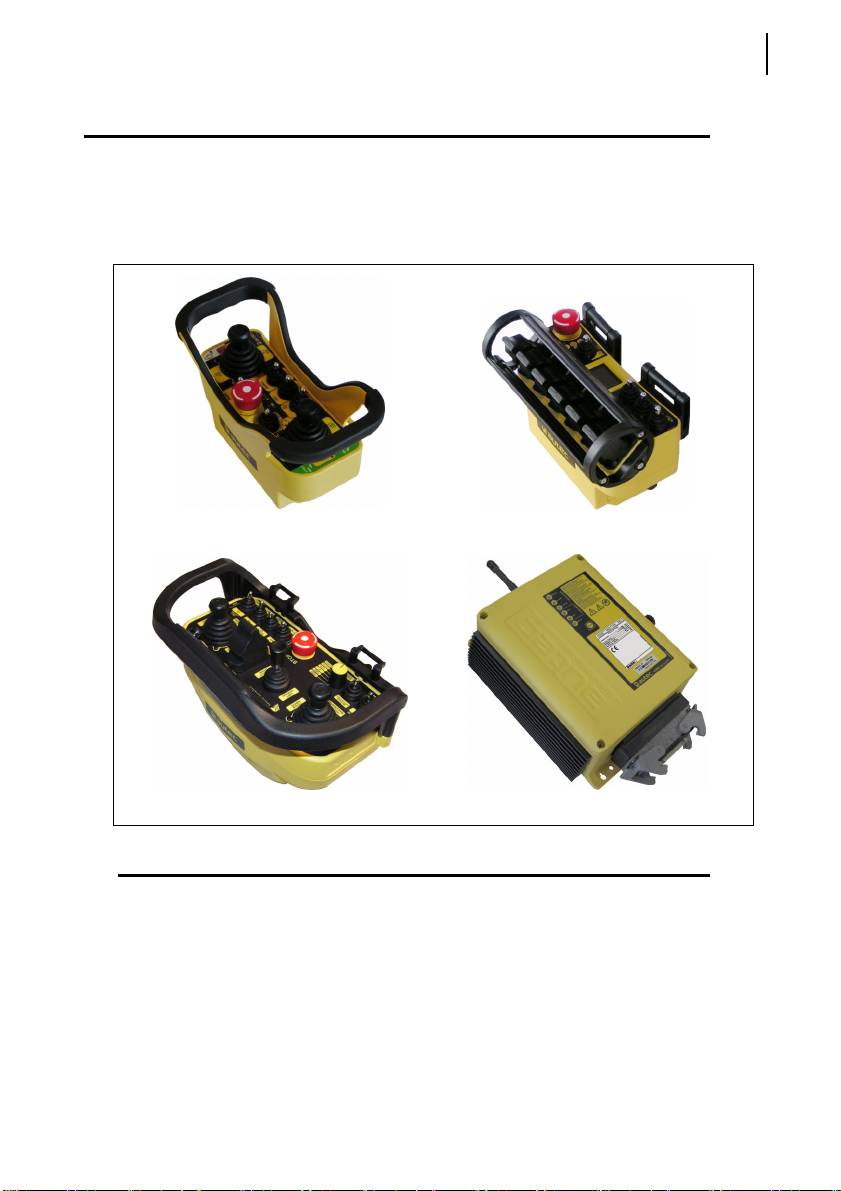
5 FJS transmitting unit ............................................................................................... 65
5.1 Description ......................................................................................................... 65
5.2 Technical data .................................................................................................... 65
5.3 Light signals ....................................................................................................... 66
6 FJL transmitting unit ............................................................................................... 68
6.1 Description ......................................................................................................... 68
6.2 Technical data .................................................................................................... 68
6.3 Light signals ....................................................................................................... 69
7 FJM transmitting unit .............................................................................................. 70
7.1 Description ......................................................................................................... 70
7.2 Technical data .................................................................................................... 71
7.3 Light signals ....................................................................................................... 71
8 ARM receiving unit .................................................................................................. 73
8.1 Description ......................................................................................................... 73
8.2 Mother board ...................................................................................................... 74
8.3 Technical data .................................................................................................... 74
8.4 Light signals ....................................................................................................... 75
9 Warnings .................................................................................................................. 78
9.1 Before starting to work ....................................................................................... 78
9.2 During normal operation .................................................................................... 78
9.3 After using the radio remote control ................................................................... 79
10 Radio remote control lifecycle ............................................................................... 80
10.1 Transportation and storage ................................................................................ 80
1
LIUDYN2AC0-00_eng.fm User manual
AUTEC - Dynamic Series

2
10.2 Installation .......................................................................................................... 80
10.3 Use ..................................................................................................................... 81
10.4 Radio remote control maintenance .................................................................... 81
10.5 Machine maintenance ........................................................................................ 84
10.6 Disposal ............................................................................................................. 84
11 General operating instructions .............................................................................. 85
11.1 Starting up the radio remote control ................................................................... 85
11.2 Command activation .......................................................................................... 85
11.3 Data Feedback Function .................................................................................... 85
11.4 Radio link interruption ........................................................................................ 86
11.5 Transmitting unit automatic switch off ................................................................ 86
11.6 Switching off the transmitting unit ...................................................................... 87
11.7 Switching off the receiving unit .......................................................................... 87
12 Working .................................................................................................................... 88
12.1 BATTERY .......................................................................................................... 88
12.2 S-KEY ................................................................................................................ 88
12.3 START pushbutton ............................................................................................ 89
12.4 STOP ................................................................................................................. 89
12.5 Command meaning ............................................................................................ 90
12.6 Low Power function ............................................................................................ 91
12.7 Wire control ........................................................................................................ 92
13 Values of proportional outputs .............................................................................. 94
13.1 REMOTE SETUP procedure ............................................................................. 94
13.2 Restoring factory settings .................................................................................. 95
14 Data memory backup .............................................................................................. 96
15 Troubleshooting ...................................................................................................... 97
15.1 Radio remote controls with Data Feedback function ......................................... 97
15.2 Radio remote controls with wire control ............................................................. 97
15.3 Solutions in case of malfunction ........................................................................ 98
The documentation enclosed with the user manual of Dynamic series radio remote controls
always consists at least of:
- battery charger manual
- technical data sheet
- guarantee booklet and its related validation slip.
When purchasing a radio remote control, make sure that all the following documents are supplied: if they are not, please ask for a copy from Autec, reporting the radio remote control serial
number (S/N).
The documentation must be kept for the whole life of the radio remote control: after reading it,
keep it on hand for future reference.
AUTEC - Dynamic Series
User manual
1 User manual
This manual is intended for Autec Dynamic series radio remote controls.
It contains warnings, information and instructions for:
- FJS, FJL and FJM transmitting units
- ARM receiving units.
User manual
General instructions
3
FJS transmitting unit
FJM transmitting unit
FJL transmitting unit
ARM receiving unit
1.1 General instructions
This manual is an integral part of the radio remote control and it aims at providing
the instructions needed for using and maintaining the system, with an eye on its
safety functions.
Always remember that:
- photos and drawings in this manual are useful examples that help understand
the instructions and warnings of each radio remote control configuration
- if necessary, contact Autec if any of the instructions and/or warnings given in
this manual are not clear.
LIUDYN2AC0-00_eng.fm User manual
AUTEC - Dynamic Series
User manual
4
Symbol conventions
No part of this manual may be reproduced, in any form or by any means, without
written permission of Autec (including recording and photocopying).
If this manual is lost or damaged, ask Autec for a copy. Please specify the serial
number of the related radio remote control.
Information contained in this manual adds to and completes the information provided by the manufacturer of the remote controlled and/or by those who install the
radio remote control on the machine.
All installation, usage and maintenance operations must be carried out by qualified technicians who are suitably trained with respect to the relevant norms and
laws.
Therefore, this manual must be read and understood in all its parts by the user
and by:
- the radio remote control owner and/or installer
- the person responsible for and in charge of maintenance and/or safety in the
As for instructions and warnings regarding the machine where the radio remote
control is installed, follow the instructions given in the machine's manual.
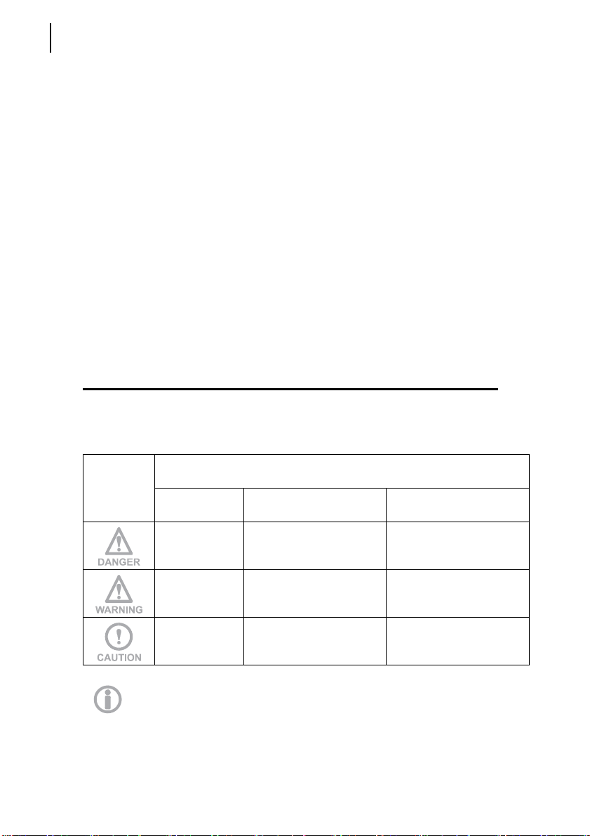
1.2 Symbol conventions
Three symbols are employed in this manual, which are used to highlight specific
safety-related issues. They are classified according to the hazardous situation
that may arise and on the possible consequences:
workplace where the radio remote control is used.
If the highlighted instructions are not respected, this leads to
Symbol
hazardous situations with the following characteristics:
dangerous
situation
gravity of consequences
for people
gravity of consequences
for property
…highly
probable.
… probable.
… probable.
This symbol is also used, and it identifies texts to be read carefully.
AUTEC - Dynamic Series
User manual
… critical (death or
physical damage).
… critical (death or
physical damage).
… moderate (non-severe
physical damage).
… critical.
… critical.
… moderate.

Documentation
Battery charger manual
2 Documentation
2.1 Battery charger manual
The battery charger manual contains instructions and warnings for a correct use
of the battery charger and of batteries.
It is included in the battery charger package.
2.2 Technical data sheet
The technical data sheet contains the transmitting unit configuration and shows
the matching between commands sent and machine functions/movements.
It also contains the wiring diagram showing the connection between the receiving
unit and the machine.
Two copies of the technical data sheet are provided together with the ARM receiving unit: one is inside the receiving unit and the other one is enclosed with this
manual. Both technical data sheets must be filled in, checked and signed by the
installer, who is responsible for a correct wiring.
Please keep one technical data sheet inside the receiving unit and the other together with this manual (always keep a copy of this data sheet for administrative
purposes).
5
The wiring of the receiving unit outputs must always reflect the wiring indicated in the technical data sheet.
2.3 Guarantee
Guarantee terms and conditions for the radio remote control are stated in the related booklet.
LIUDYN2AC0-00_eng.fm User manual
AUTEC - Dynamic Series
Dynamic series description
6
Conformity
3 Dynamic series description
3.1 Conformity
Dynamic series radio remote controls working within the frequency band 915 -
928 MHz are allowed to be used in the North American market.
Each of these radio remote controls complies with the following requirements:
- FCC (Federal Communication Commission) Part 15
IC (Industry Canada) RSS-102
Unit FCC ID IC number
FJS OQA-FJSNF022 9061A-FJSNF022
FJL OQA-FJLNF022 9061A-FJLNF022
FJM OQA-FJMNF022 9061A-FJMNF022
ARM OQA-ARMNB022 9061A-ARMNB022
Autec Dynamic series industrial
radio remote controls are used to
control machines from a distance,
without physical connections (i.e.
wires or connecting cables) between the user and the machine.
Each of these industrial radio remote controls consists of a portable transmitting unit, from which
the user can remotely control the
machine, and a receiving unit installed on board the machine itself.
Operation is subject to the following two conditions:
(1) this device may not cause harmful interference, and
(2) this device must accept any interference received, including interference that
may cause undesired operation.
Changes or modifications not expressly approved by the party responsible for
compliance could void the user’s authority to operate the equipment.
AUTEC - Dynamic Series
User manual

Dynamic series description
Applications
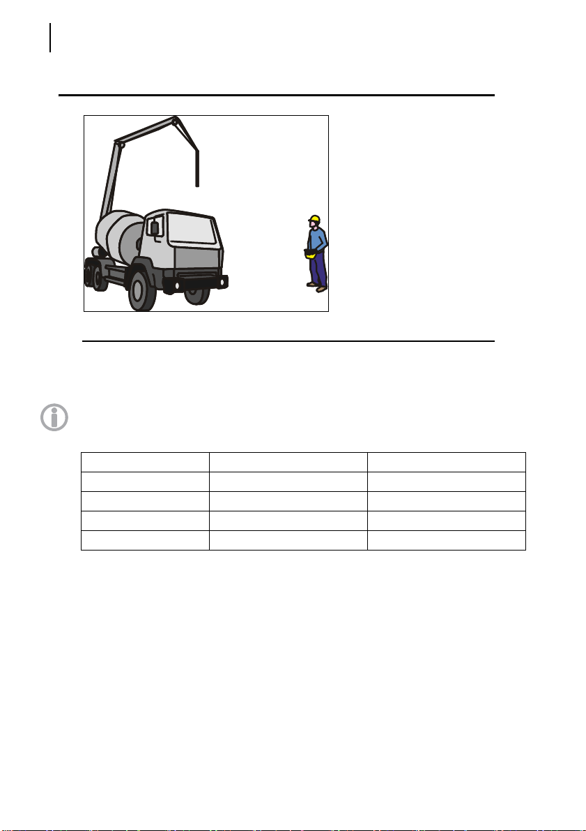
3.2 Applications
In compliance with the risk analysis (see chapter 4), this radio remote control can
be installed on hoisting and material handling machines and on machines for
moving, raising and transporting people (i.e. hydraulic cranes, aerial work platforms, telehandlers, concrete pumps).
This radio remote control cannot be installed:
- on machines installed in places where equipment with explosion-proof
characteristics is required
- on machines where the receiving unit power supply does not come from
a battery or from a power supply unit with safety isolating transformer
- to control loads that are not isolated from AC power supply (if that is the
case)
- on machines that may generate dangerous situations if they stop due to
the loss of radio link
- on machines for which a risk analysis (see chapter 4) is not possible or
gave negative results.
Autec cannot be held responsible if the radio remote control is installed on forbidden applications.
3.3 Radio link
7
The two units constantly communicate with one another through a radio link. This
is an essential requirement to ensure safety for the radio remote controlled machine.
An address is stored in the S-KEY (see paragraph 12.2) and in the address key
on the IDK connector in the receiving unit (see paragraph 8.1); the units use this
address to code their messages. This address is unique (Autec produces it only
once), univocal (specific for each radio remote control) and not reproducible.
Each unit can only decode the messages coming from the unit with the same address. This prevents messages from other radio equipment from activating any
system function.
The units send coded messages to one another:
- messages sent by the transmitting unit contain operational commands to be
carried out by the machine
- messages sent by the receiving unit contain information useful for the automatic management of the working frequency and information about measurements collected from the machine (Data Feedback function).
LIUDYN2AC0-00_eng.fm User manual
AUTEC - Dynamic Series

Dynamic series description
8
Frequencies
3.4 Frequencies
The radio link between the units of Autec Dynamic series radio remote controls
is built at one of the frequencies permitted by the European standards in force
when the system is put on the market.
Dynamic series industrial radio remote controls communicate either in dynamic
or static mode. Mode is set by the machine manufacturer.
3.4.1 Dynamic mode
A radio remote control communicating in dynamic mode:
- uses a working frequency in the band 863 - 870 MHz
- checks that the frequency is free before using it
- continually changes the working frequency to maintain the radio link even
when interference occurs.
3.4.2 Static mode
A radio remote control communicating in static mode:
- uses a working frequency in the band 869.7 - 870 MHz
- checks that the frequency is free before using it
- always works at the same frequency until the stop function is activated (see
paragraph 3.6.1).
3.5 Classification of commands
Commands sent by the transmitting unit are classified according to their type.
3.5.1 Command type: analogue, digital or direction command
Commands sent by the transmitting unit can either be analogue or digital.
Analogue commands generate proportional outputs as a function of the position
of the corresponding actuator.
Digital commands switch the status of their corresponding output, according to
the position of the related actuator. This status can either be on or off.
Direction commands are digital commands paired with analogue commands, and
are used to specify the movement direction.
3.5.2 Name of commands
All commands sent by the transmitting unit are identified by abbreviations, which
are also written in the technical data sheet to highlight the match between commands sent and machine functions.
The names of outputs in the receiving unit are not the names of commands.
Check the technical data sheet to know which name they were given.
AUTEC - Dynamic Series
User manual

Dynamic series description
Safety functions
3.6 Safety functions
Autec radio remote controls are equipped with some functions that provide high
safety levels, in order to safeguard the safety of people and property.
3.6.1 Stop function
The stop function brings the machine to a safe state every time it is necessary to
stop it due to a potentially hazardous situation. This function is either voluntarily
enabled by the user (active stop), as appropriate, or it cuts in automatically and
autonomously (passive stop).
Active stop
Active stop is a function enabled by the STOP pushbutton (see paragraph 12.4).
The transmitting unit sends to the receiving unit a command that immediately
stops the machine. When the STOP pushbutton is pressed, the machine stops in
shorter time than when passive stop cuts in.
Passive stop
Passive stop is a function that cuts in when a fault occurs during operation. When
the radio link is incorrect or interrupted, the receiving unit autonomously stops the
radio remote control. The cut-in time of this function (passive stop cut-in time) is
set by the machine manufacturer (see technical data sheet).
3.6.2 Protection against unintended movements from the standstill position
(UMFS)
This safety function protects the system “machine+radio remote control” from unintended movements, namely machine movements not activated intentionally by
the user, but resulting from possible electrical and mechanical failure of the radio
remote control.
Such safety function checks the neutral (rest) position of the actuators that control
the machine's movements. Each time one of those actuators is operated, the
transmitting unit sends both the movement command and the “SAFETY” command. Depending on the specific application, outputs related to these commands
are wired in series; alternatively the SAFETY command's outputs drive the safety
device provided on the machine.
9
LIUDYN2AC0-00_eng.fm User manual
AUTEC - Dynamic Series

Dynamic series description
10
Dynamic series technical data
3.7 Dynamic series technical data
Frequency band in dynamic mode ............................................................... 915 - 928 MHz
Frequency band in static mode .................................................................... 915 - 928 MHz
Transmitting power .............................. meets the requirements for free-license apparatus
Available radio channels................................................................................................ 260
Available radio channels with static mode .................................................................... 260
Channel spacing ....................................................................................................... 50 kHz
Hamming distance ........................................................................................................ ≥ 15
Probability of undetected error.................................................................................. < 10
Typical working range....................................................................... 100 m [approx. 330 ft]
Working range with Low Power function............................................. 30 m [approx. 100 ft]
Command response time ................................................................................. 80 - 130 ms
Active stop cut-in time (typical) ............................................................................... < 80 ms
Active stop cut-in time (maximum)........................................................................... 130 ms
Passive stop cut-in time
Performance Level of safety functions according to EN ISO 13849-1:
STOP protection .................................................................................. PL e (4-wire wiring)
STOP protection .................................................................................. PL d (2-wire wiring)
Protection against unintended movements from the standstill position (UMFS) ......... PL d
1
............................................................................... 0.5 / 1.2 / 2 s
-15
1. Passive stop cut-in time is set by the machine manufacturer (see technical data
sheet)
AUTEC - Dynamic Series
User manual
Dynamic series description
Identifying the radio remote control
3.8 Identifying the radio remote control
The serial number (S/N) is the only reference to be used to uniquely identify the
radio remote control, both if maintenance is needed and when providing statements to competent bodies.
The serial number (S/N) and other information regarding the radio remote control
are provided in some plates both on the transmitting and on the receiving unit.
These plates must not be:
- removed from their position (removal will invalidate the guarantee)
- altered or damaged (contact Autec for replacement).
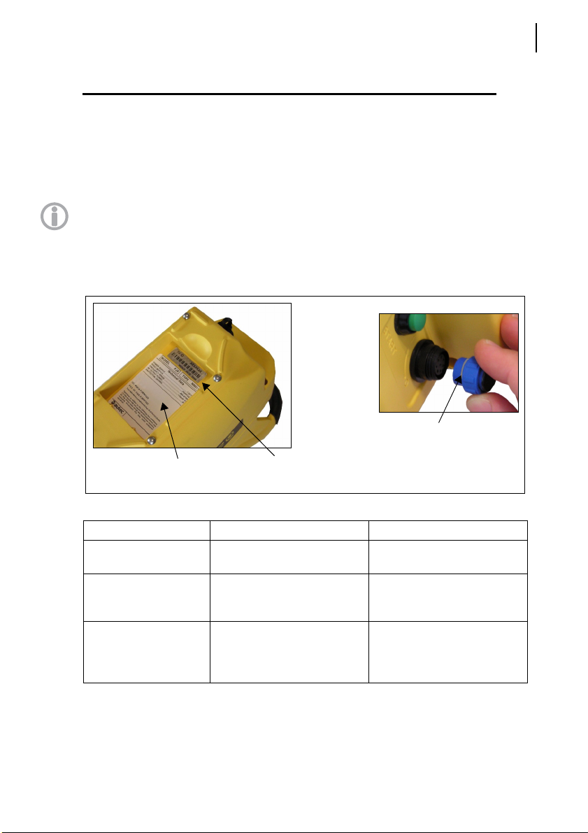
3.8.1 Plates on the transmitting unit
The transmitting unit has three plates.
radio remote control
identification plate
technical data plate
transmitting unit identification plate
11
Plate Position Content
radio remote control
identification plate
transmitting unit
identification plate
technical data plate
LIUDYN2AC0-00_eng.fm User manual
On the S-KEY: remove the SKEY to read the plate.
In the battery housing: remove
the battery to read the plate.
In the battery housing: remove
the battery to read the plate.
Radio remote control serial
number (S/N).
Manufacturing year, bar code
and transmitting unit identification number (TU ID).
MODEL, TYPE and main
transmitting unit technical
data, marking and possible
radio remote control marks.
AUTEC - Dynamic Series
Dynamic series description
12
Identifying the radio remote control
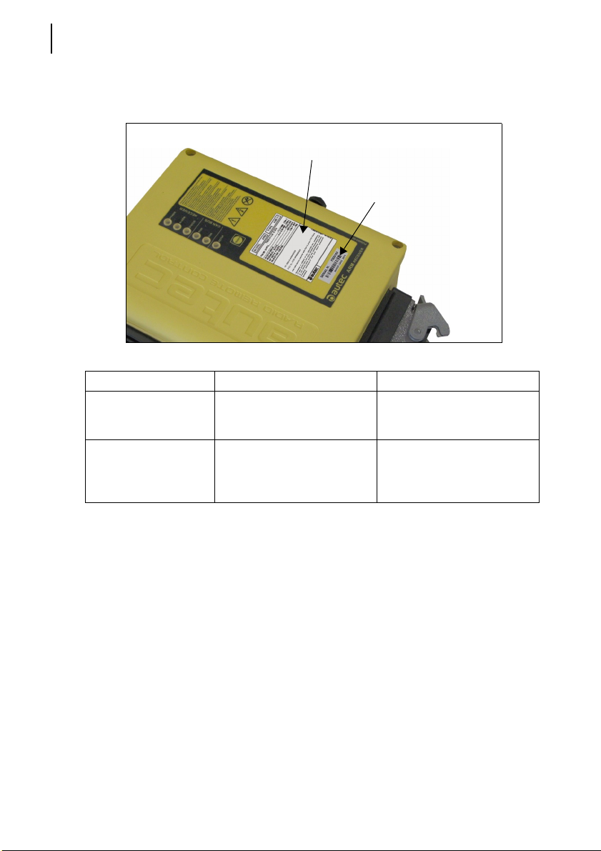
3.8.2 Plates on the receiving unit
The receiving unit has two plates.
Plate Position Content
radio remote control
identification plate
technical data plate
technical data plate
On the cover of the receiving
unit
On the cover of the receiving
unit
radio remote control
identification plate
Manufacturing year, bar code
and radio remote control serial
number (S/N).
MODEL, TYPE and main
receiving unit technical data,
marking and possible radio
remote control marks.
AUTEC - Dynamic Series
User manual

Risk analysis for radio remote controlled machines
Risk analysis
4 Risk analysis
As required by the standards, all machines must undergo a risk analysis. It is
therefore necessary to evaluate, within the limits of this analysis, if the machine
can be radio remote controlled.
The radio remote control can only be used if this analysis gives positive results.
4.1 Risk analysis for radio remote controlled machines
All warnings listed in this manual must also be taken into account during risk analysis and when setting out protection measures for the controlled machine.
When carrying out risk analysis for the machine or for the system where the radio
remote control is installed, the following must be considered:
- some machines cannot be radio remote controlled by Dynamic series radio remote controls (see paragraph 3.2)
- the radio link between the two units may be interrupted due to persistent disturbance or interference.
Whenever the radio link is interrupted (i.e. due to active stop, passive stop, low
battery, automatic switch off, receiving unit not powered):
- all outputs in the receiving unit are disabled (if this generates a hazardous situation, it is necessary that the corresponding commands are kept active)
- it is not possible to enable or disable the machine commands until the radio
remote control is started up again.
13
Due to the characteristics of radio propagation (i.e.: EM interference, near out-ofrange condition), a delay up to the “Passive stop time” (see paragraph 3.7) may
occasionally occur from the moment a command in the transmitting unit is released to the moment its corresponding output in the receiving unit is deactivated.
Those who decide upon the installation of the radio remote control must make
sure that this delay never leads to a dangerous situation in the specific uses.
The transmitting unit housing is manufactured so that it protects the actuators
from unintentional activation, while meeting at the same time the operating
needs, the comfort requirements and law limits.
Assessment shall be made to establish possible additional protection measures
for the actuators (i.e. commands requiring two-hand operation, “dead-man” function) if particular environments, equipment and working modes could cause accidental bumps to the actuators.
The machine manufacturer and/or the person who decides upon radio remote
control use and installation is responsible for this risk analysis.
Autec cannot be held responsible if this analysis is not carried out correctly.
LIUDYN2AC0-00_eng.fm User manual
AUTEC - Dynamic Series

Risk analysis
14
Working conditions
If required by the risk analysis, draw up protection measures to prevent, reduce
and report potential hazard situations.
4.2 Working conditions
To guarantee correct radio remote control operation, all current regulations regarding safety at work and accident prevention should be respected. All applicable standards and regulations valid in the user country regarding the use of both
the machine and the radio remote control must always be respected.
Autec cannot be held responsible if the radio remote control is used in unlawful
working conditions.
AUTEC - Dynamic Series
User manual

5 FJS transmitting unit
5.1 Description
A
FJS transmitting unit
B
D
C
E
Description
F
G
15
A connector for wire control (if present) B
C STOP pushbutton D display or LED (if present)
E LEDs F START pushbutton
G S-KEY (electronic starting key)
actuators (joysticks, selectors,
pushbuttons)
5.2 Technical data
Power supply (battery MBM06MH)................................................................. NiMH 7.2 V
Antenna ................. .................................................................................................. internal
Housing material ........................................................................................... PA 6 (20% fg)
Protection degree ..........................................................................................................IP65
Dimensions ............................................................ 258 x 170 x 126 mm [10.2’’ x 6.7’’ x 5’’]
Weight............................................................................................................1.3 kg [2.9 lbs]
Run time (at 20°C) ....................................................................................................... 11 h
Run time with Data Feedback (at 20°C) ..................................................................... 9.5 h
Run time with Low Power (at 20°C) ............................................................................. 14 h
Run time with Data Feedback and Low Power (at 20°C) ......................................... 12.5 h
LIUDYN2AC0-00_eng.fm User manual
AUTEC - Dynamic Series

FJS transmitting unit
16
Light signals
5.3 Light signals
FJS transmitting units may have two or three LEDs near the STOP pushbutton.
5.3.1 Light signals with two LEDs
The left LED is green, the right LED is red, and
they provide information regarding the radio remote control.
The green LED ...
Meaning
... is off The transmitting unit is switched off.
... blinks fast
... blinks slowly
The red LED
The transmitting unit is switched on and there is no
radio link.
The radio remote control is started and the radio link is
present.
a
...
Meaning
... is off The transmitting unit works correctly.
...blinks The battery is nearly flat.
b
... is on for 2 seconds
... blinks once
... blinks twice
b
b
The transmitting unit does not work correctly.
At power on, the transmitting unit detects that the
STOP pushbutton is activated or damaged.
At power on, the transmitting unit detects that one of
the commands D2-D20 or SAFETY is activated or
damaged (see technical data sheet).
At power on, the transmitting unit detects that the bat-
... blinks three times
... blinks four times
b
tery is flat.
At power on, the transmitting unit detects that one of
b
the commands A1-A8, L1-L8 and H1-H8 is activated or
damaged (see technical data sheet).
a. An acoustic signal is also heard when the red LED is illuminated.
b. After this signal, the transmitting unit switches off.
AUTEC - Dynamic Series
User manual

5.3.2 Light signals with three LEDs
Side LEDs are red and provide information
coming from the machine (Data Feedback function).
The central LED is bicolour, green and red. The
green LED is inhibited when the red one is on:
the green LED signals only appear when the red
ones pause. The central LED provides information about the radio remote control.
Central LED is green
and it ...
... is off The transmitting unit is switched off.
... blinks fast
... blinks slowly
The transmitting unit is switched on and there is no
radio link.
The radio remote control is started and the radio link is
present.
Meaning
FJS transmitting unit
Light signals
17
Central LED is red
and it ...
a
Meaning
... is off The transmitting unit works correctly.
...blinks The battery is nearly flat.
b
... is on for 2 seconds
... blinks once
... blinks twice
b
b
The transmitting unit does not work correctly.
At power on, the transmitting unit detects that the
STOP pushbutton is activated or damaged.
At power on, the transmitting unit detects that one of
the commands D2-D20 or SAFETY is activated or
damaged (see technical data sheet).
At power on, the transmitting unit detects that the bat-
... blinks three times
... blinks four times
b
tery is flat.
At power on, the transmitting unit detects that one of
b
the commands A1-A8, L1-L8 and H1-H8 is activated or
damaged (see technical data sheet).
a. An acoustic signal is also heard when the red LED is illuminated.
b. After this signal, the transmitting unit switches off.
AUTEC - Dynamic Series
LIUDYN2AC0-00_eng.fm User manual

FJL transmitting unit
18
Description
6 FJL transmitting unit
6.1 Description
B
B
A
A connector for wire control (if present) B
C STOP pushbutton D display or LED (if present)
E LEDs F START pushbutton
G S-KEY (electronic starting key)
D
actuators (joysticks, selectors,
pushbuttons)
C
E
F
G
6.2 Technical data
Power supply (battery MBM06MH)................................................................. NiMH 7.2 V
Antenna ................. .................................................................................................. internal
Housing material ........................................................................................... PA 6 (20% fg)
Protection degree ..........................................................................................................IP65
Dimensions ........................................................... 221 x 170 x 134 mm [8.7’’ x 6.7’’ x 5.3’’]
Weight............................................................................................................1.4 kg [3.1 lbs]
Run time (at 20°C) ....................................................................................................... 11 h
Run time with Data Feedback (at 20°C) ..................................................................... 9.5 h
Run time with Low Power (at 20°C) ............................................................................. 14 h
Run time with Data Feedback and Low Power (at 20°C) ......................................... 12.5 h
AUTEC - Dynamic Series
User manual

FJL transmitting unit
6.3 Light signals
FJL transmitting units have four LEDs on the left of the STOP
pushbutton:
- a green LED, identified with , providing information
about the radio remote control.
- a red LED, identified with , providing information about
the radio remote control.
- two red LEDs (the two lower ones) that may provide information
coming from the machine (Data Feedback function).
The green LED ...
... is off The transmitting unit is switched off.
... blinks fast
... blinks slowly
The transmitting unit is switched on and there is no
radio link.
The radio remote control is started and the radio link is
present.
Meaning
Light signals
19
The red LED
a
...
Meaning
... is off The transmitting unit works correctly.
...blinks The battery is nearly flat.
b
... is on for 2 seconds
... blinks once
... blinks twice
b
b
The transmitting unit does not work correctly.
At power on, the transmitting unit detects that the
STOP pushbutton is activated or damaged.
At power on, the transmitting unit detects that one of
the commands D2-D20 or SAFETY is activated or
damaged (see technical data sheet).
At power on, the transmitting unit detects that the bat-
... blinks three times
... blinks four times
b
tery is flat.
At power on, the transmitting unit detects that one of
b
the commands A1-A8, L1-L8 and H1-H8 is activated or
damaged (see technical data sheet).
a. An acoustic signal is also heard when the red LED is illuminated.
b. After this signal, the transmitting unit switches off.
AUTEC - Dynamic Series
LIUDYN2AC0-00_eng.fm User manual

FJM transmitting unit
20
Description
7 FJM transmitting unit
7.1 Description
B
C
B
B
A
F
connector for wire control
A
(if present)
C STOP pushbutton D display or LED (if present)
E LEDs F START pushbutton
G S-KEY (electronic starting key)
B
EBDBB
G BB
B
actuators (joysticks, selectors, pushbuttons)
AUTEC - Dynamic Series
User manual

FJM transmitting unit
Technical data
7.2 Technical data
Power supply (battery MBM06MH)................................................................. NiMH 7.2 V
Antenna ................. .................................................................................................. internal
Housing material ........................................................................................... PA 6 (20% fg)
Protection degree ..........................................................................................................IP65
Dimensions ......................................................... 310 x 210 x 190 mm [12.2’’ x 8.3’’ x 7.5’’]
Weight............................................................................................................2.5 kg [5.5 lbs]
Run time (at 20°C) ....................................................................................................... 11 h
Run time with Data Feedback (at 20°C) ..................................................................... 9.5 h
Run time with Low Power (at 20°C) ............................................................................. 14 h
Run time with Data Feedback and Low Power (at 20°C) ......................................... 12.5 h
7.3 Light signals
The FJM transmitting units may have two or four LEDs.
In both cases, two LEDs are always available, providing information regarding the
radio remote control.
- a green LED identified with
- a red LED identified with
21
The green LED ...
... is off The transmitting unit is switched off.
... blinks fast
... blinks slowly
LIUDYN2AC0-00_eng.fm User manual
The transmitting unit is switched on and there is no
radio link.
The radio remote control is started and the radio link is
present.
Meaning
AUTEC - Dynamic Series

FJM transmitting unit
22
Light signals
The red LEDa...
Meaning
... is off The transmitting unit works correctly.
...blinks The battery is nearly flat.
b
... is on for 2 seconds
... blinks once
... blinks twice
b
b
The transmitting unit does not work correctly.
At power on, the transmitting unit detects that the
STOP pushbutton is activated or damaged.
At power on, the transmitting unit detects that one of
the commands D2-D20 or SAFETY is activated or
damaged (see technical data sheet).
At power on, the transmitting unit detects that the bat-
... blinks three times
... blinks four times
b
tery is flat.
At power on, the transmitting unit detects that one of
b
the commands A1-A8, L1-L8 and H1-H8 is activated or
damaged (see technical data sheet).
a. An acoustic signal is also heard when the red LED is illuminated.
b. After this signal, the transmitting unit switches off.
If it has 4 LEDs, the side LEDs are red and provide information coming from the
machine (Data Feedback function).
AUTEC - Dynamic Series
User manual

8 ARM receiving unit
8.1 Description
ARM receiving unit
Description
23
A
B
C
D
E
A
F
E
A mounting holes
B antenna
C LEDs
D TEACH pushbutton
E connector for cable control
F plug
The receiving unit communicates with the machine through the outputs and their
wiring and/or through a CAN network (of which it is a slave node).
The STOP (STOP_1 and STOP_2) and SAFETY (SAF_1 and SAF_2) outputs
are some of the receiving unit's outputs.
LIUDYN2AC0-00_eng.fm User manual
AUTEC - Dynamic Series

ARM receiving unit
A B
24
Mother board
8.2 Mother board
8.3 Technical data
C
D
E
G H
F
A fuse F1
B fuse F2
C fuse F3
D fuse F4
E fuse F5
F DTK connector (for data memory)
G IDK (for address key)
BKK connector (for backup data
H
memory)
Power supply ......................................................................................................... 8-30 V
Antenna ................................................................................................................ dedicated
Rated current of outputs STOP_1 and STOP_2 ........................................... 7.5 A (30 V )
Rated current of output SAF_1 ..................................................................... 7.5 A (30 V )
Rated current of output SAF_2 ........................................................................ 3 A (30 V )
Rated current of digital outputs ........................................................................ 4 A (30 V )
Rated current of analogue outputs (PWM) ...................................................... 2 A (30 V )
Rated current of analogue outputs (voltage) .............................................. 10 mA (28 V )
Protection SAF_2 (fuse F1) ............................................................. 3 A (32 V , autofuse)
Protection of power supply (fuse F2) ............................................. 7.5 A (32 V , autofuse)
Protection STOP_1 (fuse F3) ....................................................... 7.5 A (32 V , autofuse)
Protection STOP_2 (fuse F4) ....................................................... 7.5 A (32 V , autofuse)
Protection SAF_1 (fuse F5) .......................................................... 7.5 A (32 V , autofuse)
Housing material ............................................................................................ PA6 (30% fg)
Protection degree ..........................................................................................................IP65
Dimensions ............................................................. 200 x 230 x 95 mm [7.9’’ x 9.1’’ x 3.7’’]
Weight...............................................................................................................3 kg [6.6 lbs]
AUTEC - Dynamic Series
User manual

ARM receiving unit
Light signals
8.4 Light signals
The ARM receiving unit has six
LEDs:
- POWER is green
- ALARM is red
-STATUS is blue
- RUN is green
- ERR is red
- SETUP is yellow.
1. POWER LED (green)
The POWER LED indicates the status of the receiving unit and of the radio link.
The POWER LED ... Meaning
... is off The receiving unit is switched off.
...blinks Radio link has been built.
... is on No radio link.
25
2. ALARM LED (red)
The ALARM LED warns about anomalies in the receiving unit.
The ALARM LED ... Meaning
... is off The receiving unit works correctly.
... blinks once Error on the STOP outputs.
... blinks twice Error on the SAFETY outputs.
... blinks three times
... is on The receiving unit does not work correctly.
LIUDYN2AC0-00_eng.fm User manual
Error on the outputs corresponding to direction commands.
AUTEC - Dynamic Series

ARM receiving unit
26
Light signals
3. STATUS LED (blue)
The STATUS LED warns about anomalies on the outputs or on the power supply
and indicates the reception of data from the transmitting unit.
4. RUN LED (green)
The RUN LED indicates the status of the communication between the receiving
unit and the CAN network Master node.
The STATUS LED ... Meaning
... is off No radio link.
... blinks
slowly
... blinks
fast
... is on Over-current in one of the PWM analogue outputs.
The RUN LED ... Meaning
... is off
...blinks
... is on
Over-voltage on power supply.
The receiving unit receives data from the transmitting
unit.
The receiving unit does not work as a CAN network
node.
The receiving unit does not send commands in the
CAN network.
The receiving unit is working correctly as a node in the
CAN network.
RUN LED signals reflect the guidelines of the CANopen®, standard, CiA recommendation 303-3.
5. ERR LED (red)
The ERR LED indicates the status of the CAN communication.
The ERR LED ... Meaning
... is off The CAN communication is working correctly.
...blinks The CAN communication does not work correctly.
... is on No CAN communication.
ERR LED signals reflect the guidelines of the CANopen® standard, CiA recommendation 303-3.
AUTEC - Dynamic Series
User manual

ARM receiving unit
Light signals
6. SETUP LED (yellow)
The SETUP LED shows the status of the data memory and of the address key,
depending on the receiving unit's working status.
The SETUP LED ... Meaning
... is off The receiving unit works correctly.
... blinks once Error on the address key.
... blinks twice Error on the data memory.
The receiving unit is storing the data set through the
... blinks three times
... blinks slowly A data memory is connected to the BKK connector.
... blinks fast
... is on
REMOTE SET UP (see paragraph 13.1) or through
the “Data memory backup” (see chapter 14).
This signal has two meanings, depending on the current working status:
- the receiving unit is restoring factory settings (see
paragraph 13.2)
- an error occurred during the “Data memory backup”
(see chapter 14).
The receiving unit is in REMOTE SET UP mode (see
paragraph 13.1).
27
LIUDYN2AC0-00_eng.fm User manual
AUTEC - Dynamic Series

Warnings
28
Before starting to work
9 Warnings
In addition to all instructions provided by the machine manufacturer, by the installer of the radio remote control and by the person responsible for the safety of the
work area, users shall always respect the following warnings.
9.1 Before starting to work
The transmitting unit shall be used in a simple and comfortable way, avoiding accidental falls. The harness provided with the radio remote control
serves as such.
Stand in a position that allows the direct supervision of the remote controlled machine and its load, and stay in a place ensuring safety conditions in
respect of other operations and/or activities and/or processes that are carried out in the working environment.
Never start up or use the transmitting unit if the working conditions present
the risk of losing balance or tripping.
Always check that the mechanical operation of the STOP pushbutton is correct. If it is impossible or difficult to press this pushbutton, do not use the
radio remote control.
Only start up the transmitting unit when starting work: improper use may
cause hazardous situations.
Never start up or use the transmitting unit in closed spaces, with the machine not in sight, or outside the radio remote control typical working
range: in such cases it is in fact still possible to build a radio link, thus
causing the risk that unwanted commands be carried out by the machine.
9.2 During normal operation
Visually and directly follow all movements of the machine and its load and
remain inside the radio remote control working range.
Pay particular attention to warnings and visual and acoustic signals, and
take all measurements and steps to avoid that movements of the remote
controlled machine may lead to hazardous situations for people and/or
property.
Pay attention to the entire work area. Immediately press the STOP pushbutton when a hazardous situation occurs.
AUTEC - Dynamic Series
User manual

After using the radio remote control
Warnings
In case of malfunction, disable the system “machine+radio remote control”
until the problem has been completely solved.
9.3 After using the radio remote control
Switch off the transmitting unit when work is stopped or temporarily interrupted. Do not leave the load hanging (even when changing the battery).
Never leave the transmitting unit unguarded when the S-KEY is inserted.
Always store the S-KEY in a safe place each time it is removed from the
transmitting unit. If this key is lost, the radio remote control cannot work,
since the transmitting unit needs the address stored in the key to work with
its receiving unit.
29
LIUDYN2AC0-00_eng.fm User manual
AUTEC - Dynamic Series

Radio remote control lifecycle
30
Transportation and storage
10 Radio remote control lifecycle
To ensure a safe and long-lasting operation of Dynamic series industrial radio remote controls, carefully follow the instructions provided for each stage of the
product lifecycle.
10.1 Transportation and storage
Radio remote controls must always be transported and stored inside their original
packing until they are installed on the machine.
Environmental transportation and storage conditions are given in the following table.
Temperature Relative Humidity Air Pressure
Transportation
Storage
10.2 Installation
-40°C to +70°C
[-40°F to +158°F]
-40°C to +80°C
[-40°F to +176°F]
Class 2K3
Class 1K5
Class 2K3
95%
Class 1K3
5% to 95%
Class 2K3
70 kPa to 106 kPa
Class 1K5
70 kPa to 106 kPa
The radio remote control can only be installed and tested by competent staff that
masters the technical knowledge required to carry out these procedures and is
qualified according to the regulation of the country where the radio remote control
is mounted.
Only if the radio remote control is installed correctly can it be used safely.
Always follow the instructions provided in the technical data sheet to carry
out correct installation.
Please contact the machine manufacturer or the person who decided upon
the installation of the radio remote control for instructions and warnings regarding the installation.
Instructions to calibrate the minimum and maximum values of proportional outputs are reported in chapter 13.
AUTEC - Dynamic Series
User manual

Radio remote control lifecycle
Use
10.3 Use
The use of industrial radio remote controls is strictly limited to skilled and properly
trained personnel.
When the radio remote control is installed on mobile machines, switch off
the receiving unit when the vehicle travels.
All warnings for a correct use are given in chapter 9.
All instructions for a correct use are given in chapters 11 and 12.
Environmental working conditions are given in the following table.
Temperature Relative Humidity Air Pressure
Class 5K4H
Transmitting unit
Receiving
unit
a. The receiving unit can work at 70°C [+158°F] only if the sum of currents corre-
sponding to the loads simultaneously activated by digital and analogue outputs does not exceed 10 A.
-25°C to +55°C
[-13°F to +131°F]
Class 5K2
-25°C to +70°C
[-13°F to +158°F]
a
Class 5K2
5% to 95%
Class 5K2
70 kPa to 106 kPa
31
10.4 Radio remote control maintenance
The following instructions provide information to safely carry out routine and special maintenance operations for the radio remote control.
They shall be completed by:
- instructions provided by the machine manufacturer
- directions provided by the installer of the radio remote control on the machine
- regulations regarding safety at work and accident prevention in force in the
country where the radio remote control is used.
All fine-tuning, checking and maintenance actions carried out on the radio remote
control shall be verified and recorded by the person in charge of carrying out
maintenance on the machine.
In case of failure, emergencies or damaged parts, disable the system “radio
remote control+machine” until the problem has been completely solved.
Before any maintenance operation:
- remove the battery from the transmitting unit
- disconnect power from the receiving unit.
LIUDYN2AC0-00_eng.fm User manual
AUTEC - Dynamic Series

Radio remote control lifecycle
32
Radio remote control maintenance
After any maintenance operation:
- always make sure that commands sent by the transmitting unit only activate the corresponding expected operations
- if a unit has been opened, close it correctly, in order not to endanger its
protection degree from dust and water: check that the gasket is intact,
correctly overlay the two parts of the housing and tighten the screws.
10.4.1 Routine maintenance
Routine maintenance consists of operations needed to preserve the radio remote
control normal usage conditions, thus implementing fine-tuning, checks, planned
replacement actions that necessarily arise from the normal use of the product.
All given instructions must be followed correctly at each commissioning, that is:
- whenever the radio remote control and/or the machine is installed or assembled
- whenever the machine location/position changes
- after special maintenance.
Routine maintenance carried out as described in this manual is fundamental for
using the radio remote control safely.
Special applications may need more specific routine maintenance actions to be
carried out at different periods (i.e. if the working environment is particularly dirt,
in case of heavy applications or if the system is used very frequently, some maintenance actions may be required more frequently, depending on the decision of
the person in charge for safety in the worksite).
10.4.2 Daily routine maintenance
Before starting to work:
- make sure that the battery housing and the battery contacts are always clean
- make sure that the gaskets, bellows and caps of the actuators (joysticks, selectors and pushbuttons) are intact, soft and elastic
- make sure that the transmitting unit panel symbols can be easily recognised
and replace the panel if necessary
- check that the three plates on the transmitting unit are readable and intact
- make sure that the mechanical operation of the STOP pushbutton is correct.
During normal operation:
- check structural integrity of the transmitting unit
- make sure that materials that could endanger the transmitting unit usage and
safety (such as concrete, sand, lime, dust) do not deposit on it.
AUTEC - Dynamic Series
User manual

Radio remote control lifecycle
Radio remote control maintenance
After using the radio remote control:
- clean the transmitting unit: never use solvents or flammable/corrosive materials and do not use high-pressure water cleaners or steam cleaners
- store the transmitting unit in clean and dry areas.
10.4.3 Three-month routine maintenance
Every three months:
- remove dust or deposit of material from the receiving unit: never use solvents
or flammable/corrosive materials to clean it, and do not use high-pressure water cleaners or steam cleaners
- check structural integrity of the receiving unit
- make sure that the wiring of the receiving unit is intact and connected
- make sure that the receiving unit panel symbols can be easily recognised and
replace the panel if necessary
- check that the plates on the receiving unit are readable and intact.
10.4.4 Special maintenance
Special maintenance consists of repairs needed due to radio remote control failure, damage or malfunction, carried out with the aim of restoring the original usage and working conditions.
Prior to contacting the support service technicians of the machine's manufacturer:
- read and understand all parts of this manual, and make sure that all the instructions it contains have been accomplished correctly
- follow the instructions to detect possible malfunctions and their origins (see
chapter 15).
33
Any fault should be repaired by authorised personnel only (contact the support service of the machine's manufacturer), using original Autec spare
parts only.
The following radio remote control data must be reported in order to make interventions faster and more reliable:
- radio remote control serial number (S/N) and TU ID (transmitting unit identification number)
- purchase date (given on the certificate of guarantee)
- description of the problem found
- address and telephone number of the place where the device is being used
(with the name of the person to contact)
- local supplier.
LIUDYN2AC0-00_eng.fm User manual
AUTEC - Dynamic Series

Radio remote control lifecycle
34
Machine maintenance
10.5 Machine maintenance
Follow instructions provided by the machine manufacturer and by the installer of
the radio remote control, in order to carry out machine maintenance.
When carrying out maintenance operations on the machine:
- always remove the S-KEY from the transmitting unit
- disconnect power from the receiving unit
Disconnect the plug and the antenna from the ARM receiving unit whenever
machine maintenance is carried out (i.e. when soldering).
10.6 Disposal
When disposing of a radio remote control, give it to the waste separate collecting
services in the user's country.
Please pay particular attention when recycling the batteries: apply local rules. Do
not throw them away with domestic trash.
AUTEC - Dynamic Series
User manual

General operating instructions
Starting up the radio remote control
11 General operating instructions
11.1 Starting up the radio remote control
Starting up the radio remote control consists in building a radio link between the
transmitting and the receiving unit. For this purpose, you need to:
1. power on the receiving unit respecting the voltage limits provided in the technical data (see paragraph 8.3). The POWER LED switches on
2. power on the transmitting unit:
- insert a charged battery in the transmitting unit (see paragraph 12.1)
- insert the S-KEY in the transmitting unit. The green LED starts blinking fast
3. press the START pushbutton in the transmitting unit until the POWER LED in
the receiving unit and the green LED in the transmitting unit start blinking slowly.
11.2 Command activation
With the radio remote control started, act on the joysticks, pushbuttons and
switches corresponding to the command to be performed.
The user must be properly trained about the symbols on the transmitting unit panel, to be aware of the matching between actuators and movements on the machine (symbols used are defined by the machine manufacturer according to the
functions of the machine).
Some specific commands may be present on the transmitting unit: see
paragraph 12.5.
35
11.3 Data Feedback Function
The user receives information and/or signals concerning the controlled machine
by means of the Data Feedback function.
During normal radio remote control operation, pay particular attention to the indications displayed and signalled by the display or through the LEDs: they can be
helpful to evaluate the machine working status.
Any information shown and signalled on the display or through the LEDs
can never be considered or used as a safety signal or for legal metrology.
When operating and moving the machine, remember that the radio remote
control does not intervene autonomously when potential hazard situations
are displayed and signalled.
LIUDYN2AC0-00_eng.fm User manual
AUTEC - Dynamic Series

General operating instructions
36
Radio link interruption
11.3.1 Operation with display
If the transmitting unit has a display, it is possible to show signal icons, measurements collected from the machine and their description.
Information displayed and how it is displayed (icons and/or measurements and/
or descriptions) depend on the settings chosen by the machine manufacturer.
In addition, two indicators are always present:
- battery charge level (at the bottom on the left)
- quality of radio link (at the bottom on the right).
11.3.2 Operation with LED
If the transmitting unit has an LED array, particular machine conditions are signalled if they are on (i.e. load limits, limit switch, …).
The signalled conditions depend on the settings chosen by the machine manufacturer.
11.4 Radio link interruption
When the radio link is incorrect or interrupted for a certain period of time, the passive stop function automatically cuts in (see paragraph 3.6.1).
The green LED on the transmitting unit switches from blinking slowly to fast blinking.
The POWER LED on the receiving unit switches from blinking to steady on.
Press the START pushbutton to start the radio remote control.
11.5 Transmitting unit automatic switch off
The transmitting unit automatically switches off when:
- the battery is flat (see paragraph 11.5.1)
- the radio remote control is not used for a certain time (see paragraph 11.5.2)
- the transmitting unit is powered and never switched off for eight hours nonstop (see paragraph 11.5.3).
The green LED on the transmitting unit switches off.
The POWER LED on the receiving unit switches from blinking to steady on.
Press the START pushbutton to start the radio remote control.
11.5.1 Low battery
The transmitting unit indicates if the battery is not sufficiently charged (the red
LED blinks and an acoustic signal sounds).
The transmitting unit automatically switches off after 3.5 minutes from the beginning of the signal.
The battery shall be replaced with a charged one (see paragraph 12.1).
AUTEC - Dynamic Series
User manual

General operating instructions
Switching off the transmitting unit
11.5.2 When the transmitting unit is not used
The transmitting unit automatically switches off after the “automatic switch off time”
has elapsed; during that time, the unit stays on without movement commands activated.
The activation of this function and its cut-in time are set by the machine manufacturer (see technical data sheet).
11.5.3 Non-stop use
The transmitting unit indicates if it has been used for eight hours non-stop (the
red LED blinks and an acoustic signal sounds).
The transmitting unit automatically switches off after 3.5 minutes from the beginning of the signal.
11.6 Switching off the transmitting unit
The transmitting unit shall be switched off each time work is stopped: remove the
S-KEY (see paragraph 12.2) and always store it in a safe place.
11.7 Switching off the receiving unit
The receiving unit shall be switched off each time the radio remote control is not
used to control the machine. Remove power from the unit to switch it off.
37
When the radio remote control is installed on mobile machines, switch off
the receiving unit when the vehicle travels.
LIUDYN2AC0-00_eng.fm User manual
AUTEC - Dynamic Series

Working
38
BATTERY
12 Working
12.1 BATTERY
FJS, FJL and FJM transmitting units can only be powered through Autec rechargeable batteries.
See the battery charger manual enclosed in the packaging with the battery charger for any warnings and instructions regarding the batteries.
Batteries shall be inserted in their housing in the transmitting unit, with the technical data plate facing down and their contacts towards the contacts on the transmitting unit.
2
1
4
3
To insert a battery, proceed as follows:
1. push the battery towards the contacts on the transmitting unit
2. push the battery downwards.
To remove a battery, proceed as follows:
3. push the battery towards the contacts on the transmitting unit
4. lift the battery.
12.2 S-KEY
In the transmitting unit, the radio remote control address
is stored in the S-KEY. For this reason, the radio remote
control cannot work without this key.
The S-KEY can only be used in the transmitting unit
of the radio remote control where it belongs (main
transmitting unit).
AUTEC - Dynamic Series
User manual

Working
START pushbutton
As the radio remote control address is stored in the S-KEY, use it with utmost care to reduce risks that may result from incorrect handling.
If the main transmitting unit cannot be used because it has been lost or
damaged, the back-up transmitting unit can be used instead. In this case,
insert the S-KEY in the back-up unit. The back-up unit is identical to the
main unit; the only difference is the presence of the plate “BACK-UP UNIT”
on the battery housing.
12.3 START pushbutton
The START pushbutton is used to:
- start up the radio remote control (see paragraphs 11.1,
11.4 and 11.5)
- activate the horn when the radio remote control is started.
12.4 STOP
The STOP pushbutton should be pressed when it is necessary to stop the
machine immediately when a dangerous condition should occur.
When the STOP pushbutton is pressed, the machine stops
(active stop: see paragraph 3.6.1), and the transmitting unit
switches off.
To start working again after the STOP pushbutton has been
pressed:
1. make sure that the working and usage conditions are
safe
2. turn the STOP pushbutton in the arrow direction to unlock it
3. start up the radio remote control (see paragraph 11.1).
39
LIUDYN2AC0-00_eng.fm User manual
AUTEC - Dynamic Series

Working
40
Command meaning
12.5 Command meaning
Commands on the transmitting unit are established according to the machine's
operations and functions. They are established by the machine manufacturer,
who also chooses the symbols used.
Some of the commands available on the transmitting unit may be those provided
below; in this case, symbols used are generally those given here:
RPM+/- (during normal operation)
This switch increases (rpm +) or decreases (rpm -) the engine
revolutions of the remote controlled machine.
TEACH (during REMOTE SETUP)
This switch is used to calibrate minimum and maximum values
of proportional outputs (see chapter 13).
MOVEMENT SPEED SELECTOR
This switch is used to modify the movement speed. According
to the configuration:
- it sets two or three speed levels
- it increases and/or decreases speed.
These three symbols are used:
Symbol Meaning
This symbol indicates the typical machine's speed.
This symbol indicates a reduction in the machine's
speed (the reduction is set by the manufacturer).
This symbol, if present, indicates a further reduction in
the machine's speed (the reduction is set by the manufacturer).
AUTEC - Dynamic Series
User manual

ENGINE
This switch is used to switch on and off the engine of the remote
controlled machine.
Symbol Meaning
This symbol indicates that the engine is powered on.
This symbol indicates that the engine is switched off.
DISPLAY pushbutton (if the transmitting unit has a display)
This pushbutton is used to:
- activate the display lighting, if it is off
- cyclically scroll the information on the display in two different
modes:
- manual: the lines scroll up each time the pushbutton is
pressed
- automatic: when the DISPLAY pushbutton is pressed for
3 seconds, the lines scroll automatically. If the DISPLAY
pushbutton is pressed another time, it switches back to
manual mode.
It is not possible to scroll the lines if only icons are displayed.
The display lighting stays on for a time set by the machine manufacturer.
Working
Low Power function
41
12.6 Low Power function
The LOW POWER function allows transmission at a lower power than the nominal power (see paragraph 3.7) and reduces the radio remote control working
range.
This function aims at:
- making it easier to work with several systems in the same working environment (i.e.: many working machines in the same working area)
- extending the battery run-time.
This function is established by the machine manufacturer (see technical data
sheet).
LIUDYN2AC0-00_eng.fm User manual
AUTEC - Dynamic Series

42
Working
Wire control
12.7 Wire control
The wire control is used:
- in particular working conditions, established by the machine manufacturer
- when it is not possible to build a radio link between the radio remote control
units
- when working in environments where using radio frequencies is not allowed or
is dangerous
- when a fully charged battery is not available.
When using the wire control, it is not possible to eliminate the electric
shock hazard when working near in-ground or overhead high voltage electrical cables.
12.7.1 Description
The wire control connects the transmitting unit to the receiving unit through a cable that replaces the radio link. The cable must be plugged in its connector on the
transmitting unit and on the receiving unit.
AUTEC - Dynamic Series
User manual
Connector on the transmitting unit
Connector on the receiving unit

Working
Wire control
When using the wire control, the working features do not change (i.e. the meaning of actuators and the Data Feedback function).
12.7.2 Working
Before starting to work, make sure that the cable and the corresponding connectors are intact.
The wire control can only be connected and disconnected when the transmitting
unit is switched off.
After connecting or disconnecting the wire control, start up the radio remote control (see paragraph 11.1) to control the machine.
During operation with wire control:
- radio link is off
- leave the battery inside the transmitting unit, even though the power supply
comes from the receiving unit.
The battery is not, in any case, recharged through the wire control: it can only
be recharged through its appropriate battery charger provided together with
the system.
When you finish working with the cable control, disconnect the cable from the
transmitting unit and from the machine, and protect the connectors on the units
with their caps.
43
LIUDYN2AC0-00_eng.fm User manual
AUTEC - Dynamic Series

Values of proportional outputs
44
REMOTE SETUP procedure
13 Values of proportional outputs
Proportional outputs in the ARM receiving unit are factory set: values are
given in the technical data sheet.
SETUP LED in
the receiving unit
Maximum and minimum values of proportional outputs (joystick semi-axes)
can be modified using the REMOTE
SETUP procedure (see paragraph
13.1). After modifying the values it is
possible to restore factory settings, if
TEACH push-
button in the
receiving unit
necessary.
13.1 REMOTE SETUP procedure
Proportional outputs can only be calibrated by qualified and trained personnel.
This calibration is used to set maximum and minimum values for the semi-axes
of each joystick.
1. Ensure that the transmitting unit is switched off.
2. Power on the receiving unit.
3. Press the TEACH pushbutton in the receiving unit and do not release it until
the SETUP LED illuminates.
4. Insert the S-KEY in the transmitting unit.
5. Set the maximum and minimum value for the semi-axes of each joystick to be
calibrated, as described here below:
- press the START pushbutton in the transmitting unit
- to set the maximum value, move the joystick to the maximum range of the
semi-axis to be calibrated. Maintain the position and use the TEACH selector on the transmitting unit to set the desired value.
- to set the minimum value, move the joystick slightly out from the standstill
position of the semi-axis to be calibrated. Maintain the position and use the
TEACH selector on the transmitting unit to set the desired value.
- after calibrating one joystick in the transmitting unit, press the STOP push-
button to save calibrations.
Calibrations are saved in the data memory on the DTK connector.
6. To leave the procedure, press the TEACH pushbutton on the receiving unit
and do not release it until the SETUP LED switches off.
Check that the new values of proportional outputs correctly fit the machine operation and then save a copy of the data memory (see chapter 14).
AUTEC - Dynamic Series
User manual

Values of proportional outputs
Restoring factory settings
If a speed selector is present on the transmitting unit, calibration is to be performed for each of the selector positions.
If inputs of the module FSAAMI01A are used in the receiving unit to select different speeds, calibration must be performed while these inputs are active.
13.2 Restoring factory settings
This procedure is used to restore factory settings for the proportional outputs.
1. Ensure that the transmitting unit is switched off.
2. Power on the receiving unit.
3. Press the TEACH pushbutton and do not release it until the SETUP LED illuminates.
4. Press the TEACH pushbutton three times and do not release it at last pressure; the SETUP LED blinks fast: this indicates that factory settings are being
restored.
5. Release the TEACH pushbutton when the SETUP LED is steadily illuminated
again.
If the TEACH pushbutton is released before the SETUP LED is steadily illuminated, factory settings of proportional outputs will not be restored.
6. To leave the procedure, press the TEACH pushbutton on the receiving unit
and do not release it until the SETUP LED switches off.
45
LIUDYN2AC0-00_eng.fm User manual
AUTEC - Dynamic Series

Data memory backup
46
Restoring factory settings
14 Data memory backup
The receiving unit has two data memories: one is in the DTK connector on the
mother board and one is attached inside the cover (backup data memory).
When data of proportional outputs are modified, they are saved in the data memory present in the DTK connector.
The data memory in the DTK connector can be copied into a backup data memory. This is useful in case you need to restore the information contained. In this
case, use the data memory attached inside the cover.
If one of the data memories is lost or damaged, ask the machine manufacturer
for a new one.
IDK connector
BKK connector
DTK connector
Please note that information contained in the data memory in the DTK connector
overwrites the data memory of the BKK connector during the backup procedure.
Perform the following steps to copy the information of the data memory.
1. Make sure that the transmitting unit and the receiving unit are not powered.
2. Open the receiving unit
3. Make sure that a data memory is plugged in the DTK connector
4. Insert the memory attached inside the receiving unit cover in the BKK connector
5. Close the receiving unit
6. Power on the receiving unit: the SETUP LED blinks slowly
7. Press the TEACH pushbutton: the SETUP LED blinks fast (indicating that data
are being copied); release the button when the LED starts blinking slowly again.
If the TEACH pushbutton is released before the SETUP LED starts blinking
slowly again, data contained in the data memory will not be copied.
8. Disconnect power from the receiving unit.
9. Open the receiving unit, remove the data memory from the BKK connector and
attach it inside the cover.
10.Close the receiving unit.
AUTEC - Dynamic Series
User manual

Radio remote controls with Data Feedback function
Troubleshooting
15 Troubleshooting
When the radio remote control does not work:
- bring the transmitting unit close to the receiving unit to avoid radio interference
and disturbances
- establish whether the problem lies with the radio remote control or with the machine.
Therefore, before any inspection, try to control the machine from a control unit
different from the radio remote control, if present.
If the problem persists, it lies with the machine.
If not, the problem may lie with the radio remote control. In such case, please
refer to paragraph 15.3.
15.1 Radio remote controls with Data Feedback function
It is still possible that the transmitting unit sends commands to control the machine even though the Data Feedback function does not work properly, or if there
is no information and/or signals coming from it.
To check that the radio remote control works properly, please refer to
paragraph 15.3.
When the display or the LED array does not work, please contact the support
service of the machine manufacturer, even if no one of the problems indicated in
paragraph 15.3 has been detected.
47
15.2 Radio remote controls with wire control
Please refer to paragraph 15.3 to check that the radio remote control works properly.
Possibly use the wire control to check if radio interference occurs.
On the contrary, if you want to check that the wire control works properly:
- connect the cable to the transmitting unit and to the machine
- check that the manoeuvres carried out by the machine correspond to the commands sent by the transmitting unit.
LIUDYN2AC0-00_eng.fm User manual
AUTEC - Dynamic Series

Troubleshooting
48
Solutions in case of malfunction
15.3 Solutions in case of malfunction
Identify the radio remote control malfunction according to the light signals on the
units. If the problem persists after the suggested solution has been carried out,
contact the support service of the machine manufacturer.
15.3.1 Malfunction signalled by the transmitting unit
The green LED does
not switch on when the
START pushbutton is
pressed, even though
both the battery and the
S-KEY are inserted.
The green LED blinks
fast.
The red LED switches
on for 2 seconds and
then the unit switches
off.
The red LED blinks
once during start up.
The red LED blinks
twice during start up.
The red LED blinks
three times during start
up.
The red LED blinks four
times during start up.
Signals
Possible
reason
The battery is flat.
No radio link.
The transmitting unit
does not work correctly.
The STOP pushbutton
is locked or damaged.
At least one of the
actuators corresponding to commands D2D20 is activated or
damaged.
The battery is flat.
At least one of the
actuators corresponding to commands A1A8 and H1-H8 is activated or damaged.
Solutions
Replace the battery with a charged
one.
Bring the transmitting unit close to the
receiving unit.
Contact the support service of the
machine manufacturer.
Unlock the STOP pushbutton.
If this signal persists, contact the support service of the machine manufacturer.
Bring the actuators to the rest position. If this signal persists, contact the
support service of the machine manufacturer.
Replace the battery with a charged
one.
Bring the actuators to the rest position. If this signal persists, contact the
support service of the machine manufacturer.
AUTEC - Dynamic Series
User manual

15.3.2 Malfunction signalled by the receiving unit
Signals
The POWER LED is
off.
The POWER LED is
on.
The ALARM LED
blinks once.
The ALARM LED
blinks twice.
The ALARM LED
blinks three times.
The ALARM LED is on.
The STATUS LED
blinks slowly.
The STATUS LED
blinks fast and irregularly.
The STATUS LED is
on.
The RUN LED blinks.
The ERR LED blinks.
Possible
reason
The receiving unit is
switched off.
No radio link.
Error on the STOP outputs.
Error on the SAFETY
outputs.
Error on the outputs of
direction commands.
The receiving unit
does not work correctly.
Over-voltage on power
supply.
The receiving unit
loses some data sent
by the transmitting
unit.
Over-current in one of
the PWM analogue
outputs.
The receiving unit
does not send commands in the CAN network.
CAN communication
error.
Make sure that fuse F2 is intact.
Correctly plug in the connecting plug
and power on the receiving unit.
Bring the transmitting unit close to the
receiving unit.
Make sure that fuses F3 and F4 are
intact.
Correctly plug in the connecting plug.
Make sure that the STOP outputs are
wired correctly.
Make sure that fuses F1 and F5 are
intact.
Correctly plug in the connecting plug.
Make sure that the SAFETY outputs
are wired correctly.
Contact the support service of the
machine manufacturer.
Make sure that the outputs of direction commands are wired correctly.
Contact the support service of the
machine manufacturer.
Make sure that the receiving unit
power supply is within the voltage limits provided in the technical data.
Bring the transmitting unit close to the
receiving unit.
If this signal persists, contact the support service of the machine manufacturer.
Contact the support service of the
machine manufacturer.
Contact the support service of the
machine manufacturer.
Contact the support service of the
machine manufacturer.
Solutions in case of malfunction
Troubleshooting
Solutions
49
LIUDYN2AC0-00_eng.fm User manual
AUTEC - Dynamic Series

Troubleshooting
50
Solutions in case of malfunction
Signals
The SETUP LED
blinks once.
The SETUP LED
blinks twice.
The SETUP LED
blinks slowly.
Possible
reason
Error on the address
key.
Error on the data memory.
A data memory is connected to the BKK connector.
Solutions
Contact the support service of the
machine manufacturer.
Replace the data memory on the DTK
connector with the backup data memory attached inside the cover (see
chapter 14).
If you are not performing a backup of
the data memory, remove the memory from the BKK connector (see
chapter 14).
AUTEC - Dynamic Series
User manual


Autec srl
via pomaroli, 65 - 36030 Caldogno - Italy - phone +39.0444.901000 - fax +39.0444.901011 - info@autecsafety.com - www.autecsafety.com
 Loading...