

Autec FJMNF022 User Manual
Dynamic series
user manual
re
hitectu
rc
afe a
LIUDYN2AB0-01
s
FSA
ex
fl


Dynamic series
user manual
re
hitectu
rc
afe a
s
FSA
ex
fl


INDEX
1 User manual ............................................................................................................... 3
1.1 General instructions ............................................................................................. 3
1.2 Symbol conventions ............................................................................................. 4
2 Documentation .......................................................................................................... 5
2.1 Battery charger manual ........................................................................................ 5
2.2 Technical data sheet ............................................................................................ 5
2.3 Guarantee ............................................................................................................ 5
3 Dynamic series description ...................................................................................... 6
3.1 Conformity ............................................................................................................ 6
3.2 Applications .......................................................................................................... 7
3.3 Radio link ............................................................................................................. 7
3.4 Frequencies ......................................................................................................... 8
3.5 Classification of commands ................................................................................. 8
3.6 Safety functions ................................................................................................... 9
3.7 Dynamic series technical data ........................................................................... 10
3.8 Identifying the radio remote control .................................................................... 11
4 Risk analysis ............................................................................................................ 13
4.1 Risk analysis for radio remote controlled machines ........................................... 13
4.2 Working conditions ............................................................................................. 14
5 FJS transmitting unit ............................................................................................... 15
5.1 Description ......................................................................................................... 15
5.2 Technical data .................................................................................................... 15
5.3 Light signals ....................................................................................................... 16
6 FJL transmitting unit ............................................................................................... 18
6.1 Description ......................................................................................................... 18
6.2 Technical data .................................................................................................... 18
6.3 Light signals ....................................................................................................... 19
7 FJM transmitting unit .............................................................................................. 20
7.1 Description ......................................................................................................... 20
7.2 Technical data .................................................................................................... 21
7.3 Light signals ....................................................................................................... 21
8 CRS receiving unit ................................................................................................... 23
8.1 Description ......................................................................................................... 23
8.2 Technical data .................................................................................................... 24
8.3 Light signals ....................................................................................................... 24
9 Warnings for installation ........................................................................................ 26
9.1 General .............................................................................................................. 26
9.2 Mounting and fastening the receiving unit in the best position .......................... 26
9.3 Mounting and fastening the antenna in the best position ................................... 26
9.4 Wiring ................................................................................................................. 26
9.5 At end of installation ........................................................................................... 27
1
LIUDYN2AB0-01_eng.fm User manual
AUTEC - Dynamic Series

2
9.6 Testing ............................................................................................................... 27
10 Warnings for use ..................................................................................................... 28
10.1 Before starting to work ....................................................................................... 28
10.2 During normal operation .................................................................................... 28
10.3 After using the radio remote control ................................................................... 29
11 Radio remote control lifecycle ............................................................................... 30
11.1 Transportation and storage ................................................................................ 30
11.2 Installation .......................................................................................................... 30
11.3 Use ..................................................................................................................... 31
11.4 Maintenance ...................................................................................................... 31
11.5 Machine maintenance ........................................................................................ 34
11.6 Disposal ............................................................................................................. 34
12 General operating instructions .............................................................................. 35
12.1 Starting up the radio remote control ................................................................... 35
12.2 Command activation .......................................................................................... 35
12.3 Data Feedback Function .................................................................................... 35
12.4 Automatic interruption of the radio link ............................................................... 36
12.5 Transmitting unit automatic switch off ................................................................ 36
12.6 Switching off the transmitting unit ...................................................................... 37
12.7 Switching off the receiving unit .......................................................................... 37
13 Working .................................................................................................................... 38
13.1 BATTERY .......................................................................................................... 38
13.2 S-KEY ................................................................................................................ 38
13.3 START pushbutton ............................................................................................ 39
13.4 STOP ................................................................................................................. 39
13.5 Command meaning ............................................................................................ 40
13.6 Low Power function ............................................................................................ 41
13.7 Wire control ........................................................................................................ 41
14 Troubleshooting ...................................................................................................... 43
14.1 Radio remote controls with Data Feedback function ......................................... 43
14.2 Radio remote controls with wire control ............................................................. 43
14.3 Solutions in case of malfunction ........................................................................ 44
The documentation enclosed with the user manual of Dynamic series radio remote controls
always consists at least of:
- battery charger manual
- technical data sheet
- guarantee booklet and its related validation slip.
When purchasing a radio remote control, make sure that all the following documents are supplied: if they are not, please ask for a copy from Autec, reporting the radio remote control serial
number (S/N).
The documentation must be kept for the whole life of the radio remote control: after reading it,
keep it on hand for future reference.
AUTEC - Dynamic Series
User manual
1 User manual
This manual is intended for Autec Dynamic series radio remote controls.
It contains warnings, information and instructions for:
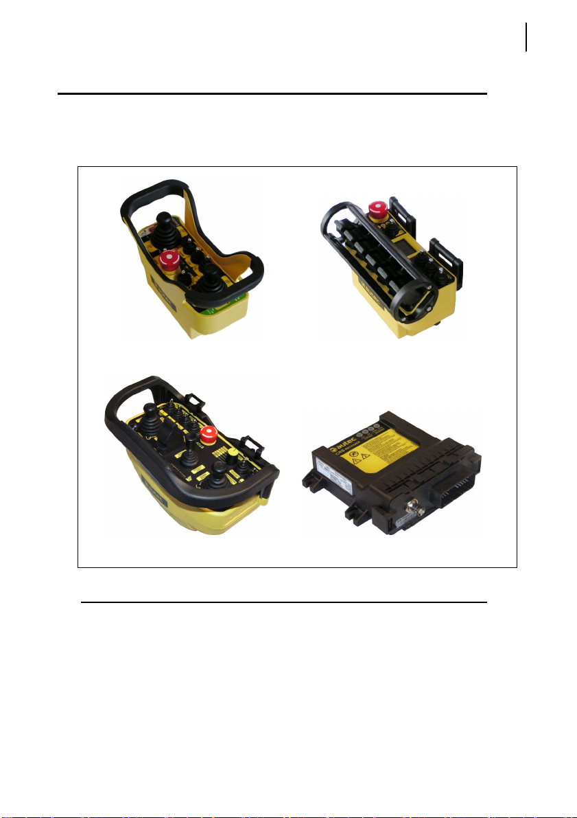
- FJS, FJL and FJM transmitting units
- CRS receiving units
User manual
General instructions
3
FJS transmitting unit
FJM transmitting unit
FJL transmitting unit
CRS receiving unit
1.1 General instructions
This manual is an integral part of the radio remote control and it aims at providing
the instructions needed for using and maintaining the system, with an eye on its
safety functions.
Always remember that:
- photos and drawings in this manual are useful examples that help understand
the instructions and warnings of each radio remote control configuration
- if necessary, contact Autec if any of the instructions and/or warnings given in
this manual are not clear.
LIUDYN2AB0-01_eng.fm User manual
AUTEC - Dynamic Series
User manual
4
Symbol conventions
No part of this manual may be reproduced, in any form or by any means, without
written permission of Autec (including recording and photocopying).
If this manual is lost or damaged, ask Autec for a copy. Please specify the serial
number of the related radio remote control.
Information contained in this manual adds to and completes the information provided by the manufacturer of the remote controlled and/or by those who install the
radio remote control on the machine.
All installation, usage and maintenance operations must be carried out by qualified technicians who are suitably trained with respect to the relevant norms and
laws.
Therefore, this manual must be read and understood in all its parts by the user
and by:
- the radio remote control owner and/or installer
- the person responsible for and in charge of maintenance and/or safety in the
As for instructions and warnings regarding the machine where the radio remote
control is installed, follow the instructions given in the machine's manual.
1.2 Symbol conventions
Three symbols are employed in this manual, which are used to highlight specific
safety-related issues. They are classified according to the hazardous situation
that may arise and on the possible consequences:
workplace where the radio remote control is used
If the highlighted instructions are not respected, this leads to
hazardous situations with the following characteristics:
Symbol
dangerous situation
gravity of
consequences for
people
gravity of
consequences for
property
…highly probable.
This symbol is also used, and it identifies texts to be read carefully.
AUTEC - Dynamic Series
User manual
…probable.
…probable.
…critical (death or
physical damage).
…critical (death or
physical damage).
… moderate
(non-severe
physical damage).
…critical.
…critical.
…moderate.

Documentation
Battery charger manual
2 Documentation
2.1 Battery charger manual
The battery charger manual contains instructions and warnings for a correct use
of the battery charger and of batteries.
It is included in the battery charger package.
2.2 Technical data sheet
The technical data sheet contains the transmitting unit configuration and shows
the matching between commands sent and machine functions/movements.
It also contains the wiring diagram showing the connection between the receiving
unit and the machine.
The technical data sheet must be filled in, checked and signed by the installer,
who is responsible for a correct wiring.
The technical data sheet must be kept together with this manual (always keep a
copy of this data sheet for administrative purposes).
The wiring of the receiving unit outputs must always reflect the wiring indicated in the technical data sheet.
5
2.3 Guarantee
Guarantee terms and conditions for the radio remote control are stated in the related booklet.
LIUDYN2AB0-01_eng.fm User manual
AUTEC - Dynamic Series
Dynamic series description
6
Conformity
3 Dynamic series description
3.1 Conformity
Dynamic series radio remote controls working within the frequency band 915 -
928 MHz are allowed to be used in the North American market.
Each of these radio remote controls complies with the following requirements:
- FCC (Federal Communication Commission) Part 15
IC (Industry Canada) RSS-102
Unit FCC ID IC number
FJS OQA-FJSNF022 9061A-FJSNF022
FJL OQA-FJLNF022 9061A-FJLNF022
FJM OQA-FJMNF022 9061A-FJMNF022
CRS OQA-CRSNA022 9061A-CRSNA022
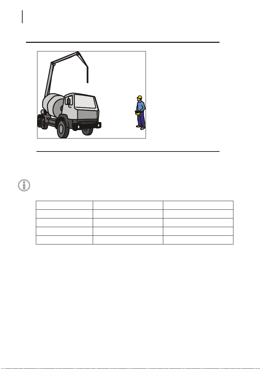
Autec Dynamic series industrial
radio remote controls are used to
control machines from a distance,
without physical connections (i.e.
wires or connecting cables) between the user and the machine.
Each of these industrial radio remote controls consists of a portable transmitting unit, from which
the user can remotely control the
machine, and a receiving unit installed on board the machine itself.
Operation is subject to the following two conditions:
(1) this device may not cause harmful interference, and
(2) this device must accept any interference received, including interference that
may cause undesired operation.
Changes or modifications not expressly approved by the party responsible for
compliance could void the user’s authority to operate the equipment.
AUTEC - Dynamic Series
User manual

Dynamic series description
Applications
3.2 Applications
In compliance with the risk analysis (see chapter 4), this radio remote control can
be installed on hoisting and material handling machines and on machines for
moving, raising and transporting people (i.e. hydraulic cranes, aerial work platforms, telehandlers, concrete pumps).
This radio remote control cannot be installed:
- on machines installed in places where equipment with explosion-proof
characteristics is required
- on machines where the receiving unit power supply does not come from
a battery or from a power supply unit with safety isolating transformer
- to control loads that are not isolated from AC power supply (if that is the
case)
- on machines that may generate dangerous situations if they stop due to
the loss of radio link
- on machines for which a risk analysis (see chapter 4) is not possible or
gave negative results.
Autec cannot be held responsible if the radio remote control is installed on forbidden applications.
3.3 Radio link
7
The two units constantly communicate with one another through a radio link. This
is an essential requirement to ensure safety for the radio remote controlled machine.
Messages from the units are coded through an address stored in the S-KEY (see
paragraph 13.2) and in the receiving unit. This address is unique (Autec produces
it only once), univocal (specific for each radio remote control) and not reproducible. Each unit can only decode the messages coming from the unit with the same
address. This prevents messages from other radio equipment from activating any
system function.
The units send coded messages to one another:
- messages sent by the transmitting unit contain operational commands to be
carried out by the machine
- messages sent by the receiving unit contain information useful for the au-
tomatic management of the working frequency and information about
measurements collected from the machine (Data Feedback function).
LIUDYN2AB0-01_eng.fm User manual
AUTEC - Dynamic Series

Dynamic series description
8
Frequencies
3.4 Frequencies
The radio link between the units of Autec Dynamic series radio remote controls
is built at one of the frequencies permitted by the European standards in force
when the system is put on the market.
Dynamic series industrial radio remote controls communicate either in dynamic
or static mode. Mode is set by the machine manufacturer.
3.4.1 Dynamic mode
A radio remote control communicating in dynamic mode:
- uses a working frequency in the band 915 - 928 MHz
- checks that the frequency is free before using it
- continually changes the working frequency to maintain the radio link even
when interference occurs.
3.4.2 Static mode
A radio remote control communicating in static mode:
- uses a working frequency in the band 915 - 928 MHz
- checks that the frequency is free before using it
- always works at the same frequency until the stop function is activated (see
paragraph 3.6.1).
3.5 Classification of commands
Commands sent by the transmitting unit are classified according to their type.
3.5.1 Command type: analogue, digital or direction command
Commands sent by the transmitting unit can either be analogue or digital.
Analogue commands generate proportional outputs as a function of the position
of the corresponding actuator.
Digital commands switch the status of their corresponding output, according to
the position of the related actuator. This status can either be on or off.
Direction commands are digital commands paired with analogue commands, and
are used to specify the movement direction.
3.5.2 Name of commands
All commands sent by the transmitting unit are identified by abbreviations, which
are also written in the technical data sheet to highlight the match between commands sent and machine functions.
The names of outputs in the receiving unit are not the names of commands.
Check the technical data sheet to know which name they were given.
AUTEC - Dynamic Series
User manual

Dynamic series description
Safety functions
3.6 Safety functions
Autec radio remote controls are equipped with some functions that provide high
safety levels, in order to safeguard the safety of people and property.
3.6.1 Stop function
The stop function brings the machine to a safe state every time it is necessary to
stop it due to a potentially hazardous situation. This function is either voluntarily
enabled by the user (active stop), as appropriate, or it cuts in automatically and
autonomously (passive stop).
Active stop
Active stop is a function enabled by the STOP pushbutton (see paragraph 13.4).
The transmitting unit sends to the receiving unit a command that immediately
stops the machine. When the STOP pushbutton is pressed, the machine stops in
shorter time than when passive stop cuts in.
Passive stop
Passive stop is a function that cuts in when a fault occurs during operation. When
the radio link is incorrect or interrupted, the receiving unit autonomously stops the
radio remote control. The cut-in time of this function (passive stop cut-in time) is
set by the machine manufacturer (see technical data sheet).
3.6.2 Protection against unintended movements from the standstill position
(UMFS)
This safety function protects the system “machine+radio remote control” from unintended movements, namely machine movements not activated intentionally by
the user, but resulting from possible electrical and mechanical failure of the radio
remote control.
Such safety function constantly checks the neutral (rest) position of the actuators
that drive the machine's movements. Each time one of those actuators is operated, the transmitting unit sends both the movement command and the “SAFETY”
command. This activates the two outputs that drive the safety device provided on
the machine.
9
LIUDYN2AB0-01_eng.fm User manual
AUTEC - Dynamic Series

Dynamic series description
10
Dynamic series technical data
3.7 Dynamic series technical data
Frequency band in dynamic mode ............................................................... 915 - 928 MHz
Frequency band in static mode .................................................................... 915 - 928 MHz
Transmitting power .............................. meets the requirements for free-license apparatus
Available radio channels................................................................................................ 260
Available radio channels with static mode .................................................................... 260
Channel spacing ....................................................................................................... 50 kHz
Hamming distance ........................................................................................................ ≥ 15
Probability of undetected error.................................................................................. < 10
Typical working range....................................................................... 100 m [approx. 330 ft]
Working range with Low Power function............................................. 30 m [approx. 100 ft]
Command response time ................................................................................. 80 - 130 ms
Active stop cut-in time (typical) ............................................................................... < 80 ms
Active stop cut-in time (maximum)........................................................................... 130 ms
Passive stop cut-in time
Performance Level of safety functions according to EN ISO 13849-1:
STOP protection .................................................................................. PL e (4-wire wiring)
STOP protection .................................................................................. PL d (2-wire wiring)
Protection against unintended movements from the standstill position (UMFS) ......... PL d
1
............................................................................... 0.5 / 1.2 / 2 s
-15
1. Passive stop cut-in time is set by the machine manufacturer (see technical data sheet)
AUTEC - Dynamic Series
User manual
Dynamic series description
Identifying the radio remote control
3.8 Identifying the radio remote control
The serial number (S/N) is the only reference to be used to uniquely identify the
radio remote control, both if maintenance is needed and when providing statements to competent bodies.
The serial number (S/N) and other information regarding the radio remote control
are provided in some plates both on the transmitting and on the receiving unit.
These plates must not be:
- removed from their position (removal will invalidate the guarantee)
- altered or damaged (contact Autec for replacement).
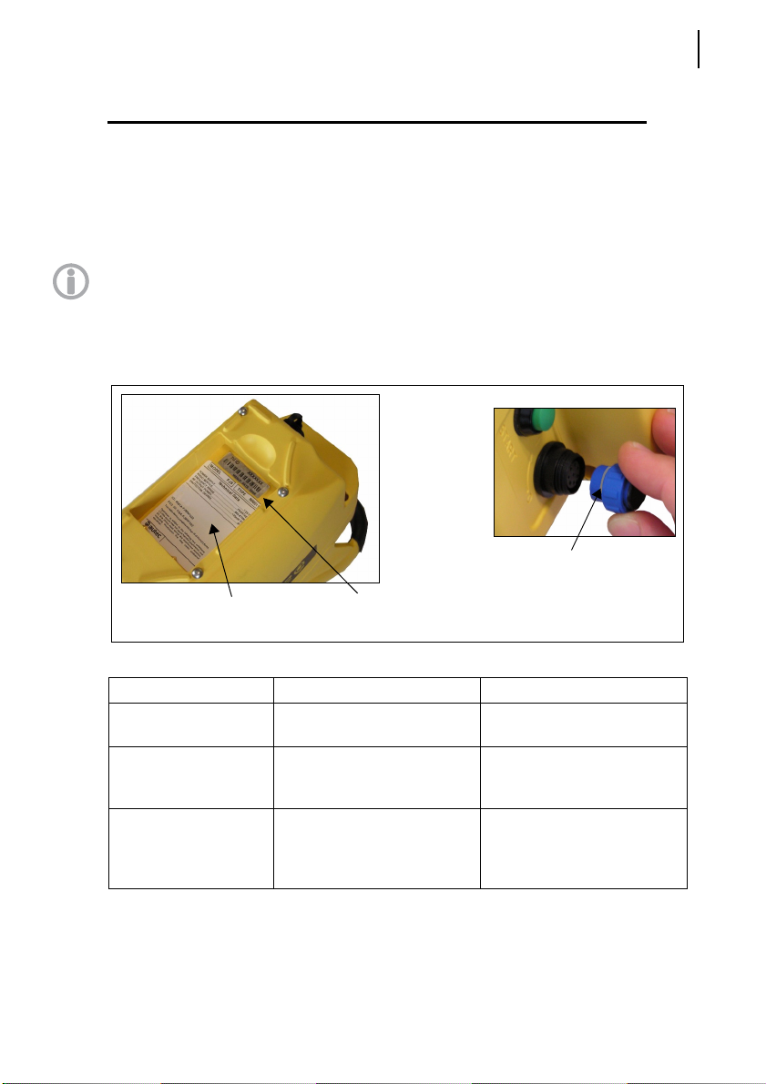
3.8.1 Plates on the transmitting unit
The transmitting unit has three plates.
radio remote control
identification plate
technical data plate
transmitting unit identification plate
11
Plate Position Content
radio remote control
identification plate
transmitting unit
identification plate
technical data plate
LIUDYN2AB0-01_eng.fm User manual
On the S-KEY: remove the SKEY to read the plate.
In the battery housing: remove
the battery to read the plate.
In the battery housing: remove
the battery to read the plate.
Radio remote control serial
number (S/N).
Manufacturing year, bar code
and transmitting unit identification number (TU ID).
MODEL, TYPE and main
transmitting unit technical
data, marking and possible
radio remote control marks.
AUTEC - Dynamic Series
Dynamic series description
12
Identifying the radio remote control
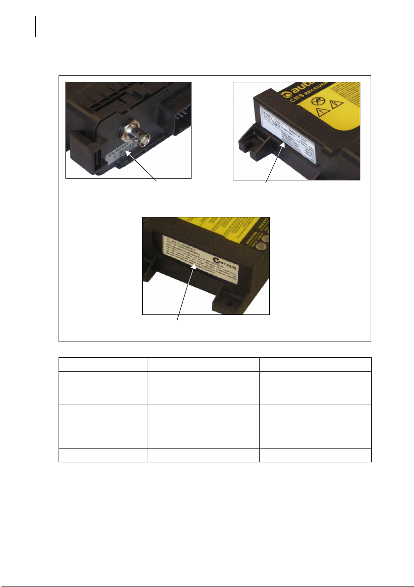
3.8.2 Plates on the receiving unit
The receiving unit has three plates.
radio remote control
identification plate
certification plate
Plate Position Content
radio remote control
identification plate
technical data plate On the left side of the casing
certification plate On the right side of the casing FCC-ID e IC number
It is on the receiving unit casing, on the connector side
technical data plate
Radio remote control serial
number (S/N), manufacturing
year and a bar code.
MODEL, TYPE and main
receiving unit technical data,
marking and possible radio
remote control marks.
AUTEC - Dynamic Series
User manual
 Loading...