


C 300 H
C 300 HI
C 300 H x4
C 300 HI x4
C 350 H
C 350 HI
C 350 H x4
C 350 HI x4
OPERATOR’S
MANUAL
ENGLISH
ORIGINAL MANUAL


AUSA
C 300 H
C 300 HI
C 300 H x4
C 300 HI x4
C 350 H
C 350 HI
C 350 H x4
C 350 HI x4
Above chassis number 57168202
ORIGINAL MANUAL


C300H / C300HI / C300H x4 / C300HI x4
C350H / C350HI / C350H x4 / C350HI x4
3
Foreword
Thank you for choosing this AUSA forklift truck (hereinafter forklift). The purpose of this
Operators and Safety Manual is to provide you, the user, with instructions concerning
the productive, safe and efficient use of this forklift. You should read and understand this
manual before operating the forklift. The Manual contains safety messages concerning
the use of the forklift. Remember that “you” are the key to safety.
The preservation of these qualities over a long period of time is in your hands. The
correct use of your forklift will allow you to make the most of the resultant benefits.
The Operator’s and Safety Manual also contains instructions for some adjustments
and for maintenance of this fork-lift. Follow these instructions carefully while performing
routine maintenance checks and keep a record of all maintenance. As wide variations
in operating conditions may be experienced, you are urged to contact your AUSA
Distributor to resolve any operational or service problems.
Please have all operators of this forklift read and understand this Operator’s and Safety
Manual.
Any damage resulting from the incorrect use of the forklift shall not be considered to
be the responsibility of AUSA. In the event of query, complaint or to place an order for
spares, please contact your Official AUSA Dealer.
This forklift is designed and intended for off highway use. If it is temporarily operated
on any public street or highway, the state and local laws governing speed, size, weight,
brakes and lighting must be complied with.
For further information you may write, FAX or E-mail to:
AUSA Center, S.L.U.
Apartado P.O.B. 194
08243 MANRESA (Barcelona) SPAIN
Tel. 34-93 874 75 52 / 93 874 73 11
Fax 34-93 873 61 39 / 93 874 12 11 / 93 874 12 55
E-mail: ausa@ausa.com
Web: http://www.ausa.com
AUSA is continuously trying to improve the efficiency, productivity and safety of its
products and reserves the right to make such improvements without incurring any
obligation to make changes to forklifts previously sold. Because of this policy of striving
for constant product improvement, the specifications and operating instructions shown
in this Operator’s and Safety Manual may be different from prior forklift models. As
such, we will not accept claims that are based on the data, illustrations or descriptions
included in these instructions.
Only original AUSA spare parts should be used. This is the only way to
guarantee that AUSA machinery has the same operational level as at the time of
delivery. No alterations should be made to the forklift without the prior authorization of
the manufacturer.
When not in use keep it stored on the forklift in the Manual holder box in the engine’s
compartment in the control valve support (fig. 1).
(fig. 1)
MOP 120213 01

4
C300H / C300HI / C300H x4 / C300HI x4
C350H / C350HI / C350H x4 / C350HI x4
Index
Uses and improper uses of the forklift .................................................................... 5
Identification of the forklift components .................................................................. 6
Vehicle Identification and Serial Numbers .............................................................. 7
Technical Specifications .......................................................................................... 8
Controls and instruments ........................................................................................ 64
Instrument Panel and controls ................................................................................ 67
Operating the forklift ................................................................................................ 73
Special procedures ................................................................................................. 78
Special Safety Messages ........................................................................................ 81
Parking the machine ............................................................................................... 89
Transporting the machine ....................................................................................... 90
Maintenance Chart .................................................................................................. 95
Periodic Maintenance Operations ........................................................................... 97
Electric circuit
C300H / C300HI ................................................................................................ 121
C300H x4 / C300HI x4 / C350H / C350HI / C350H x4 / C350HI x4 .................. 126
Hydraulic diagram (Hydraulic appliances) ............................................................. 131
Hydraulic diagram (Transmission) .......................................................................... 132
C300H / C300HI ................................................................................................ 132
C300H x4 / C300HI x4 / C350H / C350HI / C350H x4 / C350HI x4 .................. 133
Transmission Troubleshooting ................................................................................ 134
EC Declaration of conformity ................................................................................. 135

C300H / C300HI / C300H x4 / C300HI x4
C350H / C350HI / C350H x4 / C350HI x4
5
Uses and improper
Uses of the forklift
Uses for which the forklift is designed
Forklifts C300H-HI / C300H-HI x4 / C350H-HI / C350H-HI x4 have been designed and
manufactured for lifting, handling and transporting loads on rough ground and industrial
use. The safety of individuals and of the loads carried must be ensured through the use
of forks or other accessories and equipment.
ROUGH TERRAIN USE (C300H / C350H)
This forklift truck is designed for transporting and lifting loads on grounds not in good
condition, roughly flat, not too steep slopes and small obstacles, so that the stability
conditions are not optimal.
INDUSTRIAL USE (C300HI / C350HI)
This forklift truck is designed for transporting and lifting loads on good condition floors,
that means flat, levelled and paved ground, so that there are optimal stability conditions.
Any use other than that described above shall be considered inappropriate and therefore
improper.
Strict adherence to the operating, maintenance and repair conditions specified by the
manufacturer are essential in order to maintain the forklift in good working order.
Driving, maintenance and repair of the forklift should only be carried out by suitably
qualified personnel, with the necessary tools and knowledge of the control and safety
procedures relative to the forklift. When handling loads or carrying out maintenance
and/or repair work, the occupational health and safety regulations, together with those
relative to accident prevention, should be observed.
When driving with the forklift on public highways, special care should be taken to ensure
compliance with the current legislation for this type of vehicle (Highway Code).
AUSA does not assume responsibility for any damage resulting from modifications
made to the forklift without express authorization.
The texts following this symbol provide information on recycling and protecting the
environment.
Improper use
Improper use is understood to mean the use of the forklift in a manner not in keeping
with the criteria and instructions given in this Operator’s and Safety Manual and in a way
which might cause damage to persons or objects.
Some of the more common and dangerous examples of improper use are given below:
- Carrying persons other than the operator on the forklift.
- Not strictly observing the instructions for use and maintenance given in this
Operator’s and Safety Manual.
- Exceeding the limits for load and centre of gravity given in the relevant load
charts.
- Working on unstable, unshared grounds or at the edges of trenches and ditches.
- Working on excessively steep slopes.
- The use of accessories or equipment for purposes other than those for which
they have been designed.
- The use of accessories or equipment not manufactured or authorized by AUSA.

6
C300H / C300HI / C300H x4 / C300HI x4
C350H / C350HI / C350H x4 / C350HI x4
Identification of the
forklift components
a
10
a
11
a
2
a
9
Term such as right, left, front and rear when used in this Operator’s and Safety
Manual indicate the right and left sides of the machine, the front and back of the machine,
as viewed from the operators seat looking forward.
a
10
a
1
a
4
a
8
a
3
a
7
a
5
a
6
Identification components
1- Overhead guard.
2- Driving and load control (Joystick)
3- Parking brake switch.
4- Driver seat with seat belt.
5- Diesel tank.
6- Hydraulic tank.
7- Forks.
8- Lifting mast.
9- Rotating beacon.
10- Lighting equipment (¬).
11- Rear-view mirror.

C300H / C300HI / C300H x4 / C300HI x4
C350H / C350HI / C350H x4 / C350HI x4
7
V ehicle Identification
and Serial Numbers
¡Important! Write your machine Model number, date of sale, chassis and engine
serial number in the spaces provided below. Give this information to your AUSA dealer
when you need parts or information for your machine. Make a record of these numbers
in your files.
Model number: .....................................................................
Date of sale: .........................................................................
Chassis serial number: ........................................................
Engine serial number: ..........................................................
The Vehicle Identification Plate
Is located at the left of the operators seat (fig. 1).
The Chassis Serial Number
Is located on the right side of the chassis (fig. 2).
The Engine Serial Number
Is located on the left side of the engine (fig. 3, 4).
Principals components of identification plates
The plates of every components not built directly by AUSA, (for example: engines,
pumps, etc.) are directly applied on the same components, in points where the respective
makers put them origi
(fig. 3)(fig. 4) (fig. 2) (fig. 1)

8
C300H / C300HI / C300H x4 / C300HI x4
C350H / C350HI / C350H x4 / C350HI x4
Technical
Specifications
Dimensions (in)
DIMENSIONS C300H C300HI C300H x4 C300HI x4 C350H C350HI C350H x4 C350HI x4
A 7ft 2in 7ft 2in 7ft 2in 7ft 2in 7ft 4in 7ft 4in 7ft 4in 7ft 4in
B 9in 9in 8in 8in 9in 9in 8in 8in
C 1ft 1ft 1ft 1ft 1ft 2in 1ft 2in 1ft 2in 1ft 2in
D 4ft 9in 4ft 9in 4ft 9in 4ft 9in 4ft 9in 4ft 9in 4ft 9in 4ft 9in
E
(narrow axle)
E
(wide axle)
F 11ft 5in 11ft 5in 15ft 5in 15ft 5in 11ft 5in 11ft 5in 15ft 5in 15ft 5in
G 9ft 4in 9ft 4in 9ft 10in 9ft 10in 9ft 4in 9ft 4in 9ft 10in 9ft 10in
I 4,1in 4,1in 4,1in 4,1in 4,1in 4,1in 4,1in 4,1in
J 1,1in 1,1in 1,1in 1,1in 1,1in 1,1in 1,1in 1,1in
K 2ft 5in 2ft 5in 2ft 5in 2ft 5in 2ft 5in 2ft 5in 2ft 5in 2ft 5in
L 14ft 9in 14ft 9in 14ft 9in 14ft 9in 14ft 9in 14ft 9in 14ft 9in 14ft 9in
M 1ft 11in 1ft 11in 1ft 11in 1ft 11in 1ft 11in 1ft 11in 1ft 11in 1ft 11in
N 6ft 4in 6ft 4in 6ft 4in 6ft 4in 6ft 4in 6ft 4in 6ft 4in 6ft 4in
O 3ft 11in 3ft 11in 3ft 11in 3ft 11in 3ft 11in 3ft 11in 3ft 11in 3ft 11in
P 51ft 11in 51ft 11in 22ft 3in 22ft 3in 51ft 11in 51ft 11in 22ft 3in 22ft 3in
5ft 5ft 5ft 5ft 5ft 9in 5ft 9in 5ft 9in 5ft 9in
6ft 1in - 6ft 1in - 6ft 3in - 6ft 3in -
Dimensions (mm)
DIMENSIONS C300H C300HI C300H x4 C300HI x4 C350H C350HI C350H x4 C350HI x4
A 2200 2200 2200 2200 2240 2240 2240 2240
B 250 250 220 220 250 250 220 220
C 325 325 325 325 380 380 380 380
D 1460 1460 1460 1460 1460 1460 1460 1460
E
(narrow axle)
E
(wide axle)
F 3500 3500 4700 4700 3500 3500 4700 4700
G 2850 2850 3005 3005 2850 2850 3005 3005
I 120 120 120 120 120 120 120 120
J 50 50 50 50 50 50 50 50
K 750 750 750 750 750 750 750 750
L 4500 4500 4500 4500 4500 4500 4500 4500
M 600 600 600 600 600 600 600 600
N 1950 1950 1950 1950 1950 1950 1950 1950
O 1200 1200 1200 1200 1200 1200 1200 1200
P 5600 5600 6805 6805 5600 5600 6805 6805
1540 1540 1540 1540 1770 1770 1770 1770
1870 - 1870 - 1910 - 1910 -

C300H / C300HI / C300H x4 / C300HI x4
C350H / C350HI / C350H x4 / C350HI x4
9
Technical
Specifications
Mast chart (in)
Maximum
Type of mast
Dúplex (Std.) 10ft 10in Narrow / Wide (op.) 4,1in 21ft 11in 8ft 9in 21ft 11in 8ft 9in
Dúplex 13ft 1in Narrow / Wide (op.) 4,1in 9ft 9in 9ft 9,1in 9ft 9in 9ft 9,1in
Triplex (free lift)
Triplex (free lift)
Triplex (free lift)
Type of mast
Dúplex (Std.) 14ft 9in 14ft 9in 9ft 11in 9ft 11in 9ft 11in 11ft 5in 11ft 5in 11ft 5in
Dúplex 17ft 1in 17ft 1in 7ft 5in 8ft 5in 7ft 5in 9ft 11in 9ft 11in 11ft 5in
Triplex (free lift)
Triplex (free lift)
lifting
height
(mm)
12ft 1in Narrow / Wide (op.) 3ft 11in 6ft 10in 6ft 10in 6ft 10in 6ft 10in
17ft 8in Wide 5ft 6in 5ft 6in 5ft 7in 5ft 6in 5ft 7in
22ft 2in Wide 7ft 6in - 10ft 6in - 10ft 6in
Machine height with
mast extended (mm)
C300H
C300HI
C300H x4
16ft 1in 16ft 1in 7ft 11in 5ft 7in 7ft 11in 10ft 6in 10ft 6in 11ft 5in
61ft 11in 61ft 11in - 4ft 3in 4ft 11in -- 4ft 11in 11ft 11in
Front axle
C350H
C350HI
C350H x4
Free lift
(a)
C300H
C300H x4
(narrow
axle)
(mm)
Machine height with mast retracted (mm)
C300H
C300HI
Load (Kg) at max. height
(b)
C300HI
(narrow
axle)
C300H x4
(wide axle)
(a)
C300H
C350H
C350HI
(b)
C350H
C350H x4
(narrow
axle)
C300Hx4 C350Hx4
(a)
C350HI
(narrow
axle)
C350H
C350H x4
(wide axle)
(b)
Triplex (free lift)
- 25ft 7in - 3ft 4in - 3ft 11in 1ft 11in
Mast chart (mm)
Maximum
Type of mast
Dúplex (Std.) 3300 Narrow / Wide (op.) 120 2600 2670 2600 2670
Dúplex 4000 Narrow / Wide (op.) 120 2950 2990 2950 2990
Triplex (free lift)
Triplex (free lift)
Triplex (free lift)
Type of mast
Dúplex (Std.) 4500 4500 3000 3000 3000 3500 3500 3500
Dúplex 5200 5200 2250 2550 2250 3000 3000 3500
lifting
height
(mm)
3700 Narrow / Wide (op.) 1200 2090 2130 2090 2130
5400 Wide 1680 2660 2700 2660 2700
6780 Wide 2280 - 3220 - 3220
Machine height with
mast extended (mm)
C300H
C300HI
C300H x4
Front axle
C350H
C350HI
C350H x4
Free lift
(a)
C300H
C300H x4
(narrow
axle)
(mm)
Machine height with mast retracted (mm)
C300H
C300HI
Load (Kg) at max. height
(b)
C300HI
(narrow
axle)
C300H x4
(wide axle)
(a)
C300H
C350H
C350HI
(b)
C350H
C350H x4
(narrow
axle)
C300Hx4 C350Hx4
(a)
C350HI
(narrow
axle)
C350H x4
(wide axle)
(b)
C350H
Triplex (free lift)
Triplex (free lift)
Triplex (free lift)
4900 4900 2400 2700 2400 3200 3200 3500
6600 6600 - 1300 1500 -- 1500 1600
- 7820 - 1000 - 1200 600

10
C300H / C300HI / C300H x4 / C300HI x4
C350H / C350HI / C350H x4 / C350HI x4
Technical
Specifications
Diesel engine
Four cylinders, four strokes, water-cooled. Electric starter. Mixed radiator (water/oil).
C300H / C300HI:
KUBOTA V2403-M – E3B
Power 49.6 HP (36.5 kw at 2,600 rpm in accordance with SAE J 1995 Norm).
C300H x4 / C300HI x4 / C350H / C350HI / C350H x4 / C350HI x4:
KUBOTA V3600T – E3B.
Power 66 CV (48.6 kw at 2,600 rpm in accordance with SAE J 1995 Norm).
See the engine instructions handbook.
Transmission
Hydrostatic system, with variable flow pump and inching function. Hydrostatic motor
with variable flow.
Maximum operating pressure: 6092 psi. (420 bar).
4WD FullGrip® system on-demand with immediate engagement and disengagement
device.
Directional control
The selection of the drive (forwards/ backwards) is made using a switch on the lower
part of the joystick. A lamp in the shape of an arrow lights up on the top of it when a
movement mode is selected.
Steering
Hydrau lic powered with one double acting hydraulic cylinder on the rear axle.
Working pressure (all models): 2175 PSI (150 bar).
External turning circle
C300H: 11ft 5in (3500 mm) C350H: 11ft 5in (3500 mm)
C300HI: 11ft 5in (3500 mm) C350HI: 11ft 5in (3500 mm)
C300H x4: 15ft 5in (4700 mm) C350H x4: 15ft 5in (4700 mm)
C300HI x4: 15ft 5in (4700 mm) C350HI x4: 15ft 5in (4700 mm)

C300H / C300HI / C300H x4 / C300HI x4
C350H / C350HI / C350H x4 / C350HI x4
11
Technical
Specifications
Wheels
Dimensions:
Dimensions
Front wheels Rear wheels
C300H 12.5/80 - 18” (16PR) 27x10 - 12” (14PR)
C300HI 12.5/80 - 18” (16PR) 27x10 - 12” (14PR)
C300H x4 12.5/80 - 18” (16PR) 10.0/75 - 15,3” (18PR)
C300HI x4 12.5/80 - 18” (16PR) 10.0/75 - 15,3” (18PR)
C350H 16/70 - 20” (14PR) 27x10 - 12” (14PR)
C350HI 16/70 - 20” (14PR) 27x10 - 12” (14PR)
C350H x4 16/70 - 20” (14PR) 10.0/75 - 15,3” (18PR)
C350HI x4 16/70 - 20” (14PR) 10.0/75 - 15,3” (18PR)
Pressures:
Pressures
Front wheels Rear wheels
C300H 5 ± 0,5 bar 6,5 ± 0,7 bar
C300HI 5 ± 0,5 bar 6,5 ± 0,7 bar
C300H x4 5 ± 0,5 bar 5 ± 0,5 bar
C300HI x4 5 ± 0,5 bar 6 ± 0,7 bar
C350H 3,5 ± 0,4 bar 6,5 ± 0,7 bar
C350HI 3,5 ± 0,4 bar 6,5 ± 0,7 bar
C350H x4 3,5 ± 0,4 bar 5 ± 0,5 bar
C350HI x4 3,5 ± 0,4 bar 5 ± 0,5 bar
Brakes
Service brake. Multidisc sealed hydraulic brake.
Parking brake. Multidisc sealed brake spring applied, hydraulically released.
Hydraulic circuit
Activated by double gear pump; one gear for the drive circuit and one for the hydraulic
steering, connected to the hydrostatic pump of the transmission.
Pump flows:
Pump flows
C300H
C300HI
C300H x4
C300HI x4
C350H
C350HI
C350H x4
C350HI x4
Monoblock control valve with two spools and selectable solenoid for side-shift.
Restrictor valve to control the speed of the mast lowering with load.
Oil tank capacity: 22 US Gal (85 l.)
36/12 l/min a 1500 rpm
45/12 l/min a 1500 rpm
Working temperature
From 5ºF to 104F. (From -15ºC to 40ºC)

12
C300H / C300HI / C300H x4 / C300HI x4
C350H / C350HI / C350H x4 / C350HI x4
Technical
Specifications
Vibration and noise levels
Sound power level:
Warrantee sound power (according to 2000/14/EC sound emissions in the environment
by machinery for outdoor use):
• Lwa = 104 dB (A)
Sound pressure level on the operator’s site:
A weighted sound pressure in the operator’s ear measured (following norms EN 12053
and ISO 4871):
• Kubota V2403-M - E3B: Lpa = 82 dB (A)
• Kubota V3600T - E3B: Lpa = 84 dB (A)
Measurement uncertainty: 2,5 dB (A)
Vibration level produced by the machine:
Root-mean-square frequency-weighted, hand-arm vibration acceleration value:
< 2,5 m/s
Root-mean-square frequency-weighted, whole body vibration acceleration value:
< 0,5 m/s
Electrical equipment
Starter motor: Pre-heating spark plugs. Electrical starter 2,0 Kw. (V2403M-E3B engine)
and 3.0 kW (V3600T-E3B engine).
480W alternator and regulator (V2403M-E3B engine) and 720W (V3600T-E3B engine).
engine).
2
2
Battery: 12V / 110Ah (motor V2403M-E3B) y 12V / 92 Ah / 760A (V3600T-E3B engine).
Rotating beacon, horn, back-up alarm, engine oil pressure alarm, hydraulic oil level
alarm, coolant temperature alarm.
Weights
Unladen weight (with full tanks):
C 300 H-HI: 12566 lb. (5700 kg.) C 300 H-HI x4: 12566 lb. (5700 kg.)
C 350 H-HI: 13228 lb. (6000 kg.) C 350 H-HI x4: 13228 lb. (6000 kg.)
Fully laden weight:
C 300 H-HI: 19180 lb. (8700 kg.) C 300 H-HI x4: 19180 lb. (8700 kg.)
C 350 H-HI: 20944 lb. (9500 kg.) C 350 H-HI x4: 20944 lb. (9500 kg.)
Load Capacity
With the load center of the load at 19,6 inches (500 mm) (see LOAD CHARTS In this
manual)
C300H-HI / C300H-HI x4: 6614 lb. (3000 Kg.)
C350H-HI / C350H-HI x4: 7716 lb. (3500 Kg.)
With the load center at 24 inches (600 mm) (see LOAD CHARTS In this manual)
C300H-HI / C300H-HI x4: 6614 lb. (3000 Kg.)
C350H-HI / C350H-HI x4: 7716 lb. (3500 Kg.)

C300H / C300HI / C300H x4 / C300HI x4
C350H / C350HI / C350H x4 / C350HI x4
13
Technical
Specifications
Standard mast
Side-shift 3ft 11in. (1200 mm ) width
Lifting height: 10ft. 10in. (3300 mm).
Free litf: 4 in. (120 mm).
Forks length: 3ft 11in. (1200 mm).
C300H / C300HI / C300H x4 / C300HI x4
MAST Lift height (mm) h1 (mm) h2 (mm) h3 (mm) h4 (mm)
DUPLEX
TRIPLEX
3300 2480 ≥120 3250 ≥4500
4000 2830 ≥120 3950 ≥5200
3700 2130 ≥1200 3650 ≥4900
5400 2698 ≥1680 5350 ≥6600
C300H / C300HI / C300H x4 / C300HI x4
MAST Lift height (in) h1 (in) h2 (in) h3 (in) h4 (in)
DUPLEX
TRIPLEX
MAST Lift height (mm) h1 (mm) h2 (mm) h3 (mm) h4 (mm)
DUPLEX
TRIPLEX
MAST Lift height (in) h1 (in) h2 (in) h3 (in) h4 (in)
DUPLEX
TRIPLEX
10ft 10in 7ft 11in ≥4in 10ft 7in ≥14ft 9in
13ft 1in 9ft 3in ≥4in 12ft 11in ≥17ft
12ft 2in 6ft 11in ≥3ft 11in 11ft 11in ≥16ft
17ft 8in 8ft 10in ≥5ft 6in 17ft 6in ≥21ft 7in
C350H / C350HI / C350H x4 / C350HI x4
3300 2480 ≥120 3250 ≥4500
4000 2830 ≥120 3950 ≥5200
3700 2130 ≥1200 3650 ≥4900
5400 2698 ≥1680 5350 ≥6600
6850 3180 2200 6800 7780
C350H / C350HI / C350H x4 / C350HI x4
10ft 10in 7ft 11in ≥4in 10ft 7in ≥14ft 9in
13ft 1in 9ft 3in ≥4in 12ft 11in ≥17ft
12ft 2in 6ft 11in ≥3ft 11in 11ft 11in ≥16ft
17ft 8in 8ft 10in ≥5ft 6in 17ft 6in ≥21ft 7in
22ft 5in 10ft 5in 7ft 2in 22ft 3in 25ft 6in
Fork carriage
Clase FEM III.
Lifting speed
C300H
C300HI
C300H x4
C300HI x4
C350H
C350HI
C350H x4
C350HI x4
Without load: 0,42 m/sec. With load: 0,4 m/sec.
Without load: 8 ft/min. With load: 7 ft/min
Without load: 0,48 m/sec. With load: 0,48 m/sec.
Without load: 7 ft/min. With load: 7 ft/min

14
C300H / C300HI / C300H x4 / C300HI x4
C350H / C350HI / C350H x4 / C350HI x4
Technical
Specifications
Lowering speed
C300H
C300HI
C300H x4
C300HI x4
C350H
C350HI
C350H x4
C350HI x4
Without load: 21 m/min. With load: 32,2 m/min
Without load: 6 ft/min. With load: 10 ft/min
Without load: 21,6 m/min. With load: 34,8 m/min
Without load: 7 ft/min. With load: 11 ft/min
WARNING
This forklift is not designed to travel with elevated load or with the mast tilted
forward.
Do not tilt forward the mast with the forks elevated except to pick up or deposit
the load.
Control panel
The controls, switches and warning lights are integrated in the steering column and
below the joystick.
Lighting ()
Work lighting equipment, steering indicators, parking lights and warning.
Overhead guard
Manufactured according with ISO 6055.
WARNING
The operator is protected by an overhead guard which complies with the ISO
3449 and ISO 3471 / ASME B56.6 standards. It provides protection against
falling objects and together with the mast, provides protection should the
forklift overturn. The seat belt is an important part of the safety system and
should always be fastened before starting to operate the forklift. In the event of
the forklift overturning, if the seat belt is not fastened the operator may suffer
serious injury or even loss of life as a result of crushing from the forklift or even
the overhead guard itself.
Aisle widths
See graph.

C300H / C300HI / C300H x4 / C300HI x4
C350H / C350HI / C350H x4 / C350HI x4
ROUGH TERRAIN USE (C300H / C350H)
This forklift truck is designed for transporting and lifting loads on grounds not in good condition, roughly flat, not too steep slopes
and small obstacles, so that the stability conditions are not optimal.
Load charts for C300H / C300H x4 front wide axle (500 mm. load centre)
15
MOD.
CARGA MAXIMA EN TERRENO HORIZONTAL
MAX. ZULAESSIGE LAST BEI EBENEM BODEN
C300H / C300H x4
CHARGE ADMISSIBLE EN PALIER
PERMISSIBLE LOAD ON LEVEL
G kgs
D
D cm.
3000
2771
2574
3,3
3,7
4
2404
G
50 60 70 80 90 100 110 120
AUSA Center, S.L.U.
08243 MANRESA (ESPAÑA)
2255
2123
43.01350.20
2005
1900
MOD.
CARGA MAXIMA EN TERRENO HORIZONTAL
MAX. ZULAESSIGE LAST BEI EBENEM BODEN
C300H / C300H x4
CHARGE ADMISSIBLE EN PALIER
PERMISSIBLE LOAD ON LEVEL
G kgs
D
D cm.
1500
1385
1285
1202
G
5,4
50 60 70 80 90 100 110 120
AUSA Center, S.L.U.
08243 MANRESA (ESPAÑA)
1127
1061
43.01350.20
1003
950
Load charts for C300H / C300H x4 front wide axle(600 mm. load centre)
MOD.
CARGA MAXIMA EN TERRENO HORIZONTAL
MAX. ZULAESSIGE LAST BEI EBENEM BODEN
C300H / C300H x4
CHARGE ADMISSIBLE EN PALIER
PERMISSIBLE LOAD ON LEVEL
G kgs
D
D cm.
2000
1847
1716
1603
G
6,85
50 60 70 80 90 100 110 120
AUSA Center, S.L.U.
08243 MANRESA (ESPAÑA)
1503
1415
43.01350.20
1337
1267
MOD.
CARGA MAXIMA EN TERRENO HORIZONTAL
MAX. ZULAESSIGE LAST BEI EBENEM BODEN
C300H / C300H x4
CHARGE ADMISSIBLE EN PALIER
PERMISSIBLE LOAD ON LEVEL
G kgs
D
D cm.
AUSA Center, S.L.U.
08243 MANRESA (ESPAÑA)
2771
2574
G
3,3
4
3,7
60 70 80 90 100 110 120
2404
2255
2123
2005
30.12004.00
1900
MOD.
CARGA MAXIMA EN TERRENO HORIZONTAL
MAX. ZULAESSIGE LAST BEI EBENEM BODEN
C300H / C300H x4
CHARGE ADMISSIBLE EN PALIER
PERMISSIBLE LOAD ON LEVEL
G kgs
D
D cm.
08243 MANRESA (ESPAÑA)
1385
1285
1202
G
5,4
60 70 80 90 100 110 120
AUSA Center, S.L.U.
1127
1061
1003
30.12004.00
950
MOD.
CARGA MAXIMA EN TERRENO HORIZONTAL
MAX. ZULAESSIGE LAST BEI EBENEM BODEN
C300H / C300H x4
CHARGE ADMISSIBLE EN PALIER
PERMISSIBLE LOAD ON LEVEL
G kgs
D
D cm.
AUSA Center, S.L.U.
08243 MANRESA (ESPAÑA)
1847
1716
G
6,85
60 70 80 90 100 110 120
1603
1503
1415
1337
30.12004.00
1267

16
Load charts for C300H / C300H x4 front wide axle (24 in. load centre)
C300H / C300HI / C300H x4 / C300HI x4
C350H / C350HI / C350H x4 / C350HI x4
MODEL
C300H / C300H x4
MAXIMUM FORKLIFT LOAD
ON LEVEL SURFACE
G LBS
D
D inches
D = Load center extension from face of forks
6.109
5.675
5.291
G
10ft 10in
12ft 2in
13ft 1in
24 28 32 36 40 44 48
4.971
4.680
AUSA Center, S.L.U.
08243 MANRESA (SPAIN)
43.01350.28
4.420
4.189
MODEL
C300H / C300H x4
MAXIMUM FORKLIFT LOAD
ON LEVEL SURFACE
G LBS
D
D inches
D = Load center extension from face of forks
3.053
2.832
2.649
G
17ft 8in
24 28 32 36 40 44 48
2.484
2.339
AUSA Center, S.L.U.
08243 MANRESA (SPAIN)
43.01350.28
2.211
2.094
MODEL
C300H / C300H x4
MAXIMUM FORKLIFT LOAD
ON LEVEL SURFACE
G LBS
D
D inches
D = Load center extension from face of forks
4.071
3.783
3.534
G
22ft 5in
24 28 32 36 40 44 48
3.313
3.119
AUSA Center, S.L.U.
08243 MANRESA (SPAIN)
43.01350.28
2.947
2.793

C300H / C300HI / C300H x4 / C300HI x4
C350H / C350HI / C350H x4 / C350HI x4
Load charts for C300H / C300H x4 wide front axle and quick attach fork carriage (500 mm. load centre)
17
MOD.
CARGA MAXIMA EN TERRENO HORIZONTAL
MAX. ZULAESSIGE LAST BEI EBENEM BODEN
C300H / C300H x4
CHARGE ADMISSIBLE EN PALIER
PERMISSIBLE LOAD ON LEVEL
G kgs
D
D cm.
2858
2650
2469
3,3
4
3,7
2312
G
50 60 70 80 90 100 110 120
AUSA Center, S.L.U.
08243 MANRESA (ESPAÑA)
2174
2051
1941
43.01350.20
1843
MOD.
CARGA MAXIMA EN TERRENO HORIZONTAL
MAX. ZULAESSIGE LAST BEI EBENEM BODEN
C300H / C300H x4
CHARGE ADMISSIBLE EN PALIER
PERMISSIBLE LOAD ON LEVEL
G kgs
D
D cm.
1429
1325
1235
1156
G
5,4
50 60 70 80 90 100 110 120
AUSA Center, S.L.U.
08243 MANRESA (ESPAÑA)
1087
1025
43.01350.20
971
921
Load charts for C300H / C300H x4 wide front axle and quick attach fork carriage (600 mm. load centre)
MOD.
CARGA MAXIMA EN TERRENO HORIZONTAL
MAX. ZULAESSIGE LAST BEI EBENEM BODEN
C300H / C300H x4
CHARGE ADMISSIBLE EN PALIER
PERMISSIBLE LOAD ON LEVEL
G kgs
D
D cm.
AUSA Center, S.L.U.
08243 MANRESA (ESPAÑA)
2650
2469
G
3,3
4
3,7
60 70 80 90 100 110 120
2312
2174
2051
1941
30.12004.00
1843
MOD.
CARGA MAXIMA EN TERRENO HORIZONTAL
MAX. ZULAESSIGE LAST BEI EBENEM BODEN
C300H / C300H x4
CHARGE ADMISSIBLE EN PALIER
PERMISSIBLE LOAD ON LEVEL
G kgs
D
D cm.
AUSA Center, S.L.U.
08243 MANRESA (ESPAÑA)
1325
1235
G
5,4
60 70 80 90 100 110 120
1156
1087
1025
971
30.12004.00
921

C300H / C300HI / C300H x4 / C300HI x4
C350H / C350HI / C350H x4 / C350HI x4
18
Load charts for C300H / C300H x4 wide front axle and quick attach fork carriage (24 in. load centre)
MODEL
C300H / C300H x4
MAXIMUM FORKLIFT LOAD
ON LEVEL SURFACE
G LBS
D
D inches
D = Load center extension from face of forks
5.643
5.443
5.097
G
10ft 10in
13ft 1in
12ft 2in
24 28 32 36 40 44 48
4.792
4.521
AUSA Center, S.L.U.
08243 MANRESA (SPAIN)
43.01350.28
4.279
4.063
MODEL
C300H / C300H x4
MAXIMUM FORKLIFT LOAD
ON LEVEL SURFACE
G LBS
D
D inches
D = Load center extension from face of forks
2.921
2.722
2.548
G
17ft 8in
24 28 32 36 40 44 48
2.396
2.259
AUSA Center, S.L.U.
08243 MANRESA (SPAIN)
43.01350.28
2.140
2.030
C300H / C300HI / C300H x4 / C300HI x4
C350H / C350HI / C350H x4 / C350HI x4
Load charts for C300H / C300H x4 front narrow axle (500 mm. load centre)
19
MOD.
CARGA MAXIMA EN TERRENO HORIZONTAL
MAX. ZULAESSIGE LAST BEI EBENEM BODEN
C300H / C300H x4
CHARGE ADMISSIBLE EN PALIER
PERMISSIBLE LOAD ON LEVEL
G kgs
D
D cm.
3000
2771
2574
2404
G
3,3
50 60 70 80 90 100 110 120
AUSA Center, S.L.U.
08243 MANRESA (ESPAÑA)
2255
2123
43.01350.20
2005
1900
MOD.
CARGA MAXIMA EN TERRENO HORIZONTAL
MAX. ZULAESSIGE LAST BEI EBENEM BODEN
C300H / C300H x4
CHARGE ADMISSIBLE EN PALIER
PERMISSIBLE LOAD ON LEVEL
G kgs
D
D cm.
2400
2217
2060
1923
G
3,7
50 60 70 80 90 100 110 120
AUSA Center, S.L.U.
08243 MANRESA (ESPAÑA)
1804
1698
43.01350.20
1604
1520
Load charts for C300H / C300H x4 front narrow axle(600 mm. load centre)
MOD.
CARGA MAXIMA EN TERRENO HORIZONTAL
MAX. ZULAESSIGE LAST BEI EBENEM BODEN
C300H / C300H x4
CHARGE ADMISSIBLE EN PALIER
PERMISSIBLE LOAD ON LEVEL
G kgs
D
D cm.
2250
2078
1931
1803
G
4
50 60 70 80 90 100 110 120
AUSA Center, S.L.U.
08243 MANRESA (ESPAÑA)
1961
1592
43.01350.20
1504
1425
MOD.
CARGA MAXIMA EN TERRENO HORIZONTAL
MAX. ZULAESSIGE LAST BEI EBENEM BODEN
C300H / C300H x4
CHARGE ADMISSIBLE EN PALIER
PERMISSIBLE LOAD ON LEVEL
G kgs
D
D cm.
AUSA Center, S.L.U.
08243 MANRESA (ESPAÑA)
2771
2574
G
3,3
60 70 80 90 100 110 120
2404
2255
2123
2005
30.12004.00
1900
MOD.
CARGA MAXIMA EN TERRENO HORIZONTAL
MAX. ZULAESSIGE LAST BEI EBENEM BODEN
C300H / C300H x4
CHARGE ADMISSIBLE EN PALIER
PERMISSIBLE LOAD ON LEVEL
G kgs
D
D cm.
08243 MANRESA (ESPAÑA)
2217
2060
1923
G
3,7
60 70 80 90 100 110 120
AUSA Center, S.L.U.
1804
1698
1604
30.12004.00
1520
MOD.
CARGA MAXIMA EN TERRENO HORIZONTAL
MAX. ZULAESSIGE LAST BEI EBENEM BODEN
C300H / C300H x4
CHARGE ADMISSIBLE EN PALIER
PERMISSIBLE LOAD ON LEVEL
G kgs
D
D cm.
AUSA Center, S.L.U.
08243 MANRESA (ESPAÑA)
2078
1931
G
4
60 70 80 90 100 110 120
1803
1961
1592
1504
30.12004.00
1425

20
Load charts for C300H / C300H x4 front narrow axle (24 in. load centre)
C300H / C300HI / C300H x4 / C300HI x4
C350H / C350HI / C350H x4 / C350HI x4
MODEL
C300H / C300H x4
MAXIMUM FORKLIFT LOAD
ON LEVEL SURFACE
G LBS
D
D inches
D = Load center extension from face of forks
6.109
5.675
5.291
G
10ft 10in
24 28 32 36 40 44 48
4.971
4.680
AUSA Center, S.L.U.
08243 MANRESA (SPAIN)
43.01350.28
4.420
1.189
MODEL
C300H / C300H x4
MAXIMUM FORKLIFT LOAD
ON LEVEL SURFACE
G LBS
D
D inches
D = Load center extension from face of forks
4.887
4.541
4.239
G
12ft 2in
24 28 32 36 40 44 48
3.977
3.743
AUSA Center, S.L.U.
08243 MANRESA (SPAIN)
43.01350.28
3.536
3.351
MODEL
C300H / C300H x4
MAXIMUM FORKLIFT LOAD
ON LEVEL SURFACE
G LBS
D
D inches
D = Load center extension from face of forks
4.581
4.257
3.974
G
13ft 1in
24 28 32 36 40 44 48
3.728
3.509
AUSA Center, S.L.U.
08243 MANRESA (SPAIN)
43.01350.28
3.315
3.141

C300H / C300HI / C300H x4 / C300HI x4
C350H / C350HI / C350H x4 / C350HI x4
Load charts for C300H / C300H x4 front narrow axle and and quick attach fork carriage (500 mm. load centre)
21
MOD.
CARGA MAXIMA EN TERRENO HORIZONTAL
MAX. ZULAESSIGE LAST BEI EBENEM BODEN
C300H / C300H x4
CHARGE ADMISSIBLE EN PALIER
PERMISSIBLE LOAD ON LEVEL
G kgs
D
D cm.
AUSA Center, S.L.U.
08243 MANRESA (ESPAÑA)
2650
2469
G
3,3
60 70 80 90 100 110 120
2312
2174
2051
1941
30.12004.00
1843
MOD.
CARGA MAXIMA EN TERRENO HORIZONTAL
MAX. ZULAESSIGE LAST BEI EBENEM BODEN
C300H / C300H x4
CHARGE ADMISSIBLE EN PALIER
PERMISSIBLE LOAD ON LEVEL
G kgs
D
D cm.
08243 MANRESA (ESPAÑA)
2120
1976
1850
G
3,7
60 70 80 90 100 110 120
AUSA Center, S.L.U.
1739
1641
1553
30.12004.00
1474
MOD.
CARGA MAXIMA EN TERRENO HORIZONTAL
MAX. ZULAESSIGE LAST BEI EBENEM BODEN
C300H / C300H x4
CHARGE ADMISSIBLE EN PALIER
PERMISSIBLE LOAD ON LEVEL
G kgs
D
D cm.
AUSA Center, S.L.U.
08243 MANRESA (ESPAÑA)
1987
1852
G
4
60 70 80 90 100 110 120
1734
1630
1538
1456
30.12004.00
Load charts for C300H / C300H x4 front narrow axle and and quick attach fork carriage (600 mm. load centre)
1382
MOD.
CARGA MAXIMA EN TERRENO HORIZONTAL
MAX. ZULAESSIGE LAST BEI EBENEM BODEN
C300H / C300H x4
CHARGE ADMISSIBLE EN PALIER
PERMISSIBLE LOAD ON LEVEL
G kgs
D
D cm.
2858
2650
2469
2312
G
3,3
50 60 70 80 90 100 110 120
AUSA Center, S.L.U.
08243 MANRESA (ESPAÑA)
2174
2051
43.01350.20
1941
1843
MOD.
CARGA MAXIMA EN TERRENO HORIZONTAL
MAX. ZULAESSIGE LAST BEI EBENEM BODEN
C300H / C300H x4
CHARGE ADMISSIBLE EN PALIER
PERMISSIBLE LOAD ON LEVEL
G kgs
D
D cm.
2287
2120
1976
1850
G
3,7
50 60 70 80 90 100 110 120
AUSA Center, S.L.U.
08243 MANRESA (ESPAÑA)
1739
1641
43.01350.20
1553
1474
MOD.
CARGA MAXIMA EN TERRENO HORIZONTAL
MAX. ZULAESSIGE LAST BEI EBENEM BODEN
C300H / C300H x4
CHARGE ADMISSIBLE EN PALIER
PERMISSIBLE LOAD ON LEVEL
G kgs
D
D cm.
2144
1987
1852
1734
G
4
50 60 70 80 90 100 110 120
AUSA Center, S.L.U.
08243 MANRESA (ESPAÑA)
1630
1538
43.01350.20
1456
1382

C300H / C300HI / C300H x4 / C300HI x4
C350H / C350HI / C350H x4 / C350HI x4
22
Load charts for C300H / C300H x4 front narrow axle and and quick attach fork carriage (24 in. load centre)
MODEL
C300H / C300H x4
MAXIMUM FORKLIFT LOAD
ON LEVEL SURFACE
G LBS
D
D inches
D = Load center extension from face of forks
5.842
5.502
5.097
G
10ft 10in
24 28 32 36 40 44 48
4.792
4.521
AUSA Center, S.L.U.
08243 MANRESA (SPAIN)
43.01350.28
4.279
4.063
MODEL
C300H / C300H x4
MAXIMUM FORKLIFT LOAD
ON LEVEL SURFACE
G LBS
D
D inches
D = Load center extension from face of forks
4.673
4.356
4.078
G
12ft 5in
24 28 32 36 40 44 48
3.833
3.617
AUSA Center, S.L.U.
08243 MANRESA (SPAIN)
43.01350.28
3.423
3.249
MODEL
C300H / C300H x4
MAXIMUM FORKLIFT LOAD
ON LEVEL SURFACE
G LBS
D
D inches
D = Load center extension from face of forks
4.380
4.082
3.822
G
13ft 1in
24 28 32 36 40 44 48
3.593
3.390
AUSA Center, S.L.U.
08243 MANRESA (SPAIN)
43.01350.28
3.209
3.046

C300H / C300HI / C300H x4 / C300HI x4
C350H / C350HI / C350H x4 / C350HI x4
Load charts for C350H / C350H x4 front narrow axle (500 mm. load centre)
23
MOD.
CARGA MAXIMA EN TERRENO HORIZONTAL
MAX. ZULAESSIGE LAST BEI EBENEM BODEN
C350H / C350H x4
CHARGE ADMISSIBLE EN PALIER
PERMISSIBLE LOAD ON LEVEL
G kgs
D
D cm.
3500
3233
3004
2805
G
3,3
50 60 70 80 90 100 110 120
AUSA Center, S.L.U.
08243 MANRESA (ESPAÑA)
2630
2477
43.01350.20
2340
2217
MOD.
CARGA MAXIMA EN TERRENO HORIZONTAL
MAX. ZULAESSIGE LAST BEI EBENEM BODEN
C350H / C350H x4
CHARGE ADMISSIBLE EN PALIER
PERMISSIBLE LOAD ON LEVEL
G kgs
D
D cm.
3200
2956
2746
2564
G
3,7
50 60 70 80 90 100 110 120
AUSA Center, S.L.U.
08243 MANRESA (ESPAÑA)
2404
2264
43.01350.20
2139
2027
Load charts for C350H / C350H x4 front narrow axle (600 mm. load centre)
MOD.
CARGA MAXIMA EN TERRENO HORIZONTAL
MAX. ZULAESSIGE LAST BEI EBENEM BODEN
C350H / C350H x4
CHARGE ADMISSIBLE EN PALIER
PERMISSIBLE LOAD ON LEVEL
G kgs
D
D cm.
3000
2771
2574
2404
G
4
50 60 70 80 90 100 110 120
AUSA Center, S.L.U.
08243 MANRESA (ESPAÑA)
2255
2123
43.01350.20
2005
1900
MOD.
CARGA MAXIMA EN TERRENO HORIZONTAL
MAX. ZULAESSIGE LAST BEI EBENEM BODEN
C350H / C350H x4
CHARGE ADMISSIBLE EN PALIER
PERMISSIBLE LOAD ON LEVEL
G kgs
D
D cm.
AUSA Center, S.L.U.
08243 MANRESA (ESPAÑA)
3233
3004
G
3,3
60 70 80 90 100 110 120
2805
2630
2477
2340
30.12004.00
2217
MOD.
CARGA MAXIMA EN TERRENO HORIZONTAL
MAX. ZULAESSIGE LAST BEI EBENEM BODEN
C350H / C350H x4
CHARGE ADMISSIBLE EN PALIER
PERMISSIBLE LOAD ON LEVEL
G kgs
D
D cm.
08243 MANRESA (ESPAÑA)
2956
2746
2564
G
3,7
60 70 80 90 100 110 120
AUSA Center, S.L.U.
2404
2264
2139
30.12004.00
2027
MOD.
CARGA MAXIMA EN TERRENO HORIZONTAL
MAX. ZULAESSIGE LAST BEI EBENEM BODEN
C350H / C350H x4
CHARGE ADMISSIBLE EN PALIER
PERMISSIBLE LOAD ON LEVEL
G kgs
D
D cm.
AUSA Center, S.L.U.
08243 MANRESA (ESPAÑA)
2771
2574
G
4
60 70 80 90 100 110 120
2404
2255
2123
2005
30.12004.00
1900

24
Load charts for C350H / C350H x4 front narrow axle (24 in. load centre)
C300H / C300HI / C300H x4 / C300HI x4
C350H / C350HI / C350H x4 / C350HI x4
MODEL
C350H / C350H x4
MAXIMUM FORKLIFT LOAD
ON LEVEL SURFACE
G LBS
D
D inches
D = Load center extension from face of forks
7.127
6.622
6.183
G
10ft 10in
24 28 32 36 40 44 48
5.798
5.460
AUSA Center, S.L.U.
08243 MANRESA (SPAIN)
43.01350.28
5.158
4.887
MODEL
C350H / C350H x4
MAXIMUM FORKLIFT LOAD
ON LEVEL SURFACE
G LBS
D
D inches
D = Load center extension from face of forks
6.516
6.053
5.652
G
12ft 2in
24 28 32 36 40 44 48
5.299
4.991
AUSA Center, S.L.U.
08243 MANRESA (SPAIN)
43.01350.28
4.715
4.468
MODEL
C350H / C350H x4
MAXIMUM FORKLIFT LOAD
ON LEVEL SURFACE
G LBS
D
D inches
D = Load center extension from face of forks
6.109
5.674
5.299
G
13ft 1in
24 28 32 36 40 44 48
4.971
4.680
AUSA Center, S.L.U.
08243 MANRESA (SPAIN)
43.01350.28
4.420
4.188

C300H / C300HI / C300H x4 / C300HI x4
C350H / C350HI / C350H x4 / C350HI x4
Load charts for C350H / C350H x4 front narrow axle and and quick attach fork carriage (500 mm. load centre)
25
MOD.
CARGA MAXIMA EN TERRENO HORIZONTAL
MAX. ZULAESSIGE LAST BEI EBENEM BODEN
C350H / C350H x4
CHARGE ADMISSIBLE EN PALIER
PERMISSIBLE LOAD ON LEVEL
G kgs
D
D cm.
3335
3091
2881
2697
G
3,3
50 60 70 80 90 100 110 120
AUSA Center, S.L.U.
08243 MANRESA (ESPAÑA)
2536
2393
43.01350.20
2265
2150
MOD.
CARGA MAXIMA EN TERRENO HORIZONTAL
MAX. ZULAESSIGE LAST BEI EBENEM BODEN
C350H / C350H x4
CHARGE ADMISSIBLE EN PALIER
PERMISSIBLE LOAD ON LEVEL
G kgs
D
D cm.
3049
2826
2634
2466
G
3,7
50 60 70 80 90 100 110 120
AUSA Center, S.L.U.
08243 MANRESA (ESPAÑA)
2319
2188
43.01350.20
2071
1965
MOD.
CARGA MAXIMA EN TERRENO HORIZONTAL
MAX. ZULAESSIGE LAST BEI EBENEM BODEN
C350H / C350H x4
CHARGE ADMISSIBLE EN PALIER
PERMISSIBLE LOAD ON LEVEL
G kgs
D
D cm.
2858
2650
2469
2312
G
4
50 60 70 80 90 100 110 120
AUSA Center, S.L.U.
08243 MANRESA (ESPAÑA)
2174
2051
43.01350.20
1941
Load charts for C350H / C350H x4 front narrow axle and and quick attach fork carriage (600 mm. load centre)
1843
MOD.
CARGA MAXIMA EN TERRENO HORIZONTAL
MAX. ZULAESSIGE LAST BEI EBENEM BODEN
C350H / C350H x4
CHARGE ADMISSIBLE EN PALIER
PERMISSIBLE LOAD ON LEVEL
G kgs
D
D cm.
AUSA Center, S.L.U.
08243 MANRESA (ESPAÑA)
3091
2881
G
3,3
60 70 80 90 100 110 120
2697
2536
2393
2265
30.12004.00
2150
MOD.
CARGA MAXIMA EN TERRENO HORIZONTAL
MAX. ZULAESSIGE LAST BEI EBENEM BODEN
C350H / C350H x4
CHARGE ADMISSIBLE EN PALIER
PERMISSIBLE LOAD ON LEVEL
G kgs
D
D cm.
08243 MANRESA (ESPAÑA)
2826
2634
2466
G
3,7
60 70 80 90 100 110 120
AUSA Center, S.L.U.
2319
2188
2071
30.12004.00
1965
MOD.
CARGA MAXIMA EN TERRENO HORIZONTAL
MAX. ZULAESSIGE LAST BEI EBENEM BODEN
C350H / C350H x4
CHARGE ADMISSIBLE EN PALIER
PERMISSIBLE LOAD ON LEVEL
G kgs
D
D cm.
AUSA Center, S.L.U.
08243 MANRESA (ESPAÑA)
2650
2469
G
4
60 70 80 90 100 110 120
2312
2174
2051
1941
30.12004.00
1843

C300H / C300HI / C300H x4 / C300HI x4
C350H / C350HI / C350H x4 / C350HI x4
26
Load charts for C350H / C350H x4 front narrow axle and and quick attach fork carriage (24 in. load centre)
MODEL
C350H / C350H x4
MAXIMUM FORKLIFT LOAD
ON LEVEL SURFACE
G LBS
D
D inches
D = Load center extension from face of forks
6.814
6.351
5.945
G
10ft 10in
24 28 32 36 40 44 48
5.590
5.275
AUSA Center, S.L.U.
08243 MANRESA (SPAIN)
43.01350.28
4.993
4.739
MODEL
C350H / C350H x4
MAXIMUM FORKLIFT LOAD
ON LEVEL SURFACE
G LBS
D
D inches
D = Load center extension from face of forks
6.230
5.806
5.436
G
12ft 2in
24 28 32 36 40 44 48
5.112
4.823
AUSA Center, S.L.U.
08243 MANRESA (SPAIN)
43.01350.28
4.565
4.332
MODEL
C350H / C350H x4
MAXIMUM FORKLIFT LOAD
ON LEVEL SURFACE
G LBS
D
D inches
D = Load center extension from face of forks
5.842
5.443
5.097
G
13ft 1in
24 28 32 36 40 44 48
4.792
4.521
AUSA Center, S.L.U.
08243 MANRESA (SPAIN)
43.01350.28
4.279
4.063

C300H / C300HI / C300H x4 / C300HI x4
C350H / C350HI / C350H x4 / C350HI x4
Load charts for C350H / C350H x4 wide axle (500 mm. load centre)
27
MOD.
CARGA MAXIMA EN TERRENO HORIZONTAL
MAX. ZULAESSIGE LAST BEI EBENEM BODEN
C350H / C350H x4
CHARGE ADMISSIBLE EN PALIER
PERMISSIBLE LOAD ON LEVEL
G kgs
D
D cm.
3500
3223
3004
3,3
4
3,7
2508
G
50 60 70 80 90 100 110 120
AUSA Center, S.L.U.
08243 MANRESA (ESPAÑA)
2630
2477
43.01350.20
2340
2217
MOD.
CARGA MAXIMA EN TERRENO HORIZONTAL
MAX. ZULAESSIGE LAST BEI EBENEM BODEN
C350H / C350H x4
CHARGE ADMISSIBLE EN PALIER
PERMISSIBLE LOAD ON LEVEL
G kgs
D
D cm.
1600
1478
1373
1282
G
5,4
50 60 70 80 90 100 110 120
AUSA Center, S.L.U.
08243 MANRESA (ESPAÑA)
1202
Load charts for C350H / C350H x4 wide axle (600 mm. load centre)
1132
43.01350.20
1070
1014
MOD.
CARGA MAXIMA EN TERRENO HORIZONTAL
MAX. ZULAESSIGE LAST BEI EBENEM BODEN
C350H / C350H x4
CHARGE ADMISSIBLE EN PALIER
PERMISSIBLE LOAD ON LEVEL
G kgs
D
D cm.
600
554
515
481
G
6,85
50 60 70 80 90 100 110 120
AUSA Center, S.L.U.
08243 MANRESA (ESPAÑA)
451
425
43.01350.20
401
280
MOD.
CARGA MAXIMA EN TERRENO HORIZONTAL
MAX. ZULAESSIGE LAST BEI EBENEM BODEN
C350H / C350H x4
CHARGE ADMISSIBLE EN PALIER
PERMISSIBLE LOAD ON LEVEL
G kgs
D
D cm.
AUSA Center, S.L.U.
08243 MANRESA (ESPAÑA)
3233
3004
G
3,3
4
3,7
60 70 80 90 100 110 120
2805
2630
2477
2340
30.12004.00
2217
MOD.
CARGA MAXIMA EN TERRENO HORIZONTAL
MAX. ZULAESSIGE LAST BEI EBENEM BODEN
C350H / C350H x4
CHARGE ADMISSIBLE EN PALIER
PERMISSIBLE LOAD ON LEVEL
G kgs
D
D cm.
08243 MANRESA (ESPAÑA)
1478
1373
1282
G
5,4
60 70 80 90 100 110 120
AUSA Center, S.L.U.
1202
1132
1070
30.12004.00
1014
MOD.
CARGA MAXIMA EN TERRENO HORIZONTAL
MAX. ZULAESSIGE LAST BEI EBENEM BODEN
C350H / C350H x4
CHARGE ADMISSIBLE EN PALIER
PERMISSIBLE LOAD ON LEVEL
G kgs
D
D cm.
AUSA Center, S.L.U.
08243 MANRESA (ESPAÑA)
554
515
G
6,85
60 70 80 90 100 110 120
481
451
425
401
30.12004.00
280

28
Load charts for C350H / C350H x4 wide axle (24 in. load centre)
C300H / C300HI / C300H x4 / C300HI x4
C350H / C350HI / C350H x4 / C350HI x4
MODEL
C350H / C350H x4
MAXIMUM FORKLIFT LOAD
ON LEVEL SURFACE
G LBS
D
D inches
D = Load center extension from face of forks
7.127
6.622
6.183
G
10ft 10in
13ft 1in
12ft 2in
24 28 32 36 40 44 48
5.798
5.460
AUSA Center, S.L.U.
08243 MANRESA (SPAIN)
43.01350.28
5.158
4.887
MODEL
C350H / C350H x4
MAXIMUM FORKLIFT LOAD
ON LEVEL SURFACE
G LBS
D
D inches
D = Load center extension from face of forks
3.258
3.026
2.826
G
17ft 8in
24 28 32 36 40 44 48
2.649
2.495
AUSA Center, S.L.U.
08243 MANRESA (SPAIN)
43.01350.28
2.358
2.235
MODEL
C350H / C350H x4
MAXIMUM FORKLIFT LOAD
ON LEVEL SURFACE
G LBS
D
D inches
D = Load center extension from face of forks
1.221
1.135
1.060
G
22ft 5in
24 28 32 36 40 44 48
0.994
0.936
AUSA Center, S.L.U.
08243 MANRESA (SPAIN)
43.01350.28
0.884
0.617

C300H / C300HI / C300H x4 / C300HI x4
C350H / C350HI / C350H x4 / C350HI x4
Load charts for C350H / C350H x4 front wide axle and and quick attach fork carriage (500 mm. load centre)
29
MOD.
CARGA MAXIMA EN TERRENO HORIZONTAL
MAX. ZULAESSIGE LAST BEI EBENEM BODEN
C350H / C350H x4
CHARGE ADMISSIBLE EN PALIER
PERMISSIBLE LOAD ON LEVEL
G kgs
D
D cm.
3335
3091
2881
3,3
4
3,7
2697
G
50 60 70 80 90 100 110 120
AUSA Center, S.L.U.
08243 MANRESA (ESPAÑA)
2536
2393
43.01350.20
2265
2150
MOD.
CARGA MAXIMA EN TERRENO HORIZONTAL
MAX. ZULAESSIGE LAST BEI EBENEM BODEN
C350H / C350H x4
CHARGE ADMISSIBLE EN PALIER
PERMISSIBLE LOAD ON LEVEL
G kgs
D
D cm.
1524
1413
1317
1233
G
5,4
50 60 70 80 90 100 110 120
AUSA Center, S.L.U.
08243 MANRESA (ESPAÑA)
1159
1094
43.01350.20
1035
983
MOD.
CARGA MAXIMA EN TERRENO HORIZONTAL
MAX. ZULAESSIGE LAST BEI EBENEM BODEN
C350H / C350H x4
CHARGE ADMISSIBLE EN PALIER
PERMISSIBLE LOAD ON LEVEL
G kgs
D
D cm.
572
530
494
462
G
6,85
50 60 70 80 90 100 110 120
AUSA Center, S.L.U.
08243 MANRESA (ESPAÑA)
435
410
Load charts for C350H / C350H x4 front wide axle and and quick attach fork carriage (600 mm. load centre)
388
43.01350.20
369
MOD.
CARGA MAXIMA EN TERRENO HORIZONTAL
MAX. ZULAESSIGE LAST BEI EBENEM BODEN
C350H / C350H x4
CHARGE ADMISSIBLE EN PALIER
PERMISSIBLE LOAD ON LEVEL
G kgs
D
D cm.
AUSA Center, S.L.U.
08243 MANRESA (ESPAÑA)
3091
2881
G
3,3
4
3,7
60 70 80 90 100 110 120
2697
2536
2393
2265
30.12004.00
2150
MOD.
CARGA MAXIMA EN TERRENO HORIZONTAL
MAX. ZULAESSIGE LAST BEI EBENEM BODEN
C350H / C350H x4
CHARGE ADMISSIBLE EN PALIER
PERMISSIBLE LOAD ON LEVEL
G kgs
D
D cm.
08243 MANRESA (ESPAÑA)
1413
1317
1233
G
5,4
60 70 80 90 100 110 120
AUSA Center, S.L.U.
1159
1094
1035
30.12004.00
983
MOD.
CARGA MAXIMA EN TERRENO HORIZONTAL
MAX. ZULAESSIGE LAST BEI EBENEM BODEN
C350H / C350H x4
CHARGE ADMISSIBLE EN PALIER
PERMISSIBLE LOAD ON LEVEL
G kgs
D
D cm.
AUSA Center, S.L.U.
08243 MANRESA (ESPAÑA)
530
494
G
6,85
60 70 80 90 100 110 120
462
435
410
388
30.12004.00
369

C300H / C300HI / C300H x4 / C300HI x4
C350H / C350HI / C350H x4 / C350HI x4
30
Load charts for C350H / C350H x4 front wide axle and and quick attach fork carriage (24 in. load centre)
MODEL
C350H / C350H x4
MAXIMUM FORKLIFT LOAD
ON LEVEL SURFACE
G LBS
D
D inches
D = Load center extension from face of forks
6.814
6.351
5.945
G
10ft 10in
13ft 1in
12ft 2in
24 28 32 36 40 44 48
5.590
5.256
AUSA Center, S.L.U.
08243 MANRESA (SPAIN)
43.01350.28
4.993
4.739
MODEL
C350H / C350H x4
MAXIMUM FORKLIFT LOAD
ON LEVEL SURFACE
G LBS
D
D inches
D = Load center extension from face of forks
3.115
2.903
2.718
G
17ft 8in
24 28 32 36 40 44 48
2.555
2.411
AUSA Center, S.L.U.
08243 MANRESA (SPAIN)
43.01350.28
2.281
2.167
MODEL
C350H / C350H x4
MAXIMUM FORKLIFT LOAD
ON LEVEL SURFACE
G LBS
D
D inches
D = Load center extension from face of forks
1.168
1.089
1.018
G
22ft 5in
24 28 32 36 40 44 48
0.959
0.903
AUSA Center, S.L.U.
08243 MANRESA (SPAIN)
43.01350.28
0.855
0.813
C300H / C300HI / C300H x4 / C300HI x4
C350H / C350HI / C350H x4 / C350HI x4
INDUSTRIAL USE (C300HI / C350HI)
This forklift truck is designed for transporting and lifting loads on good condition floors, that means flat, levelled and paved
ground, so that there are optimal stability conditions.
Load charts for C300HI narrow axle (500 mm. load centre)
31
MOD.
CARGA MAXIMA EN TERRENO HORIZONTAL
MAX. ZULAESSIGE LAST BEI EBENEM BODEN
C300HI
CHARGE ADMISSIBLE EN PALIER
PERMISSIBLE LOAD ON LEVEL
G kgs
D cm.
3000
2771
2574
G
D
3,3
50 60 70 80 90 100 110 120
AUSA Center, S.L.U.
08243 MANRESA (ESPAÑA)
2404
2255
2123
43.01350.20
2005
1900
MOD.
CARGA MAXIMA EN TERRENO HORIZONTAL
MAX. ZULAESSIGE LAST BEI EBENEM BODEN
C300HI
CHARGE ADMISSIBLE EN PALIER
PERMISSIBLE LOAD ON LEVEL
G kgs
D cm.
2700
2500
2320
G
D
3,7
50 60 70 80 90 100 110 120
AUSA Center, S.L.U.
08243 MANRESA (ESPAÑA)
2180
2040
1930
43.01350.20
1820
1730
MOD.
CARGA MAXIMA EN TERRENO HORIZONTAL
MAX. ZULAESSIGE LAST BEI EBENEM BODEN
C300HI
CHARGE ADMISSIBLE EN PALIER
PERMISSIBLE LOAD ON LEVEL
G kgs
D cm.
2550
2310
2150
G
D
4
50 60 70 80 90 100 110 120
AUSA Center, S.L.U.
08243 MANRESA (ESPAÑA)
2010
1890
1780
43.01350.20
1690
1600
MOD.
CARGA MAXIMA EN TERRENO HORIZONTAL
MAX. ZULAESSIGE LAST BEI EBENEM BODEN
C300HI
CHARGE ADMISSIBLE EN PALIER
PERMISSIBLE LOAD ON LEVEL
G kgs
D cm.
1300
1200
1120
G
D
5,4
50 60 70 80 90 100 110 120
AUSA Center, S.L.U.
08243 MANRESA (ESPAÑA)
1050
980
920
43.01350.20
880
830

32
Load charts for C300HI narrow axle (600 mm. load centre)
C300H / C300HI / C300H x4 / C300HI x4
C350H / C350HI / C350H x4 / C350HI x4
MOD.
CARGA MAXIMA EN TERRENO HORIZONTAL
MAX. ZULAESSIGE LAST BEI EBENEM BODEN
C300HI
CHARGE ADMISSIBLE EN PALIER
PERMISSIBLE LOAD ON LEVEL
G kgs
D
D cm.
AUSA Center, S.L.U.
08243 MANRESA (ESPAÑA)
2771
2574
G
3,3
60 70 80 90 100 110 120
2404
2255
2123
2005
30.12004.00
1900
MOD.
CARGA MAXIMA EN TERRENO HORIZONTAL
MAX. ZULAESSIGE LAST BEI EBENEM BODEN
C300HI
CHARGE ADMISSIBLE EN PALIER
PERMISSIBLE LOAD ON LEVEL
G kgs
D
D cm.
AUSA Center, S.L.U.
08243 MANRESA (ESPAÑA)
2500
2320
G
3,7
60 70 80 90 100 110 120
2180
2040
1930
1820
30.12004.00
1730
MOD.
CARGA MAXIMA EN TERRENO HORIZONTAL
MAX. ZULAESSIGE LAST BEI EBENEM BODEN
C300HI
CHARGE ADMISSIBLE EN PALIER
PERMISSIBLE LOAD ON LEVEL
G kgs
D
D cm.
AUSA Center, S.L.U.
08243 MANRESA (ESPAÑA)
2310
2150
G
4
60 70 80 90 100 110 120
2010
1890
1780
1690
30.12004.00
1600
MOD.
CARGA MAXIMA EN TERRENO HORIZONTAL
MAX. ZULAESSIGE LAST BEI EBENEM BODEN
C300HI
CHARGE ADMISSIBLE EN PALIER
PERMISSIBLE LOAD ON LEVEL
G kgs
D
D cm.
AUSA Center, S.L.U.
08243 MANRESA (ESPAÑA)
1200
1120
G
5,4
60 70 80 90 100 110 120
1050
980
920
880
30.12004.00
830

C300H / C300HI / C300H x4 / C300HI x4
C350H / C350HI / C350H x4 / C350HI x4
Load charts for C300HI narrow axle (24 in. load centre)
33
MODEL
C300HI
MAXIMUM FORKLIFT LOAD
ON LEVEL SURFACE
G LBS
D
D inches
D = Load center extension from face of forks
6.109
5.675
5.291
G
10ft 10in
24 28 32 36 40 44 48
4.971
4.680
AUSA Center, S.L.U.
08243 MANRESA (SPAIN)
43.01350.28
4.420
4.189
MODEL
C300HI
MAXIMUM FORKLIFT LOAD
ON LEVEL SURFACE
G LBS
D
D inches
D = Load center extension from face of forks
5.511
5.114
4.806
G
12ft 2in
24 28 32 36 40 44 48
4.497
4.254
AUSA Center, S.L.U.
08243 MANRESA (SPAIN)
43.01350.28
4.012
3.813
MODEL
C300HI
MAXIMUM FORKLIFT LOAD
ON LEVEL SURFACE
G LBS
D
D inches
D = Load center extension from face of forks
5.092
4.739
4.431
G
13ft 1in
24 28 32 36 40 44 48
4.166
3.924
AUSA Center, S.L.U.
08243 MANRESA (SPAIN)
43.01350.28
3.725
3.527
MODEL
C300HI
MAXIMUM FORKLIFT LOAD
ON LEVEL SURFACE
G LBS
D
D inches
D = Load center extension from face of forks
2.866
2.645
2.469
G
17ft 8in
24 28 32 36 40 44 48
2.314
2.160
AUSA Center, S.L.U.
08243 MANRESA (SPAIN)
43.01350.28
2.028
1.829

34
Load charts for C350HI / C350HI x4 wide axle (500 mm. load centre)
C300H / C300HI / C300H x4 / C300HI x4
C350H / C350HI / C350H x4 / C350HI x4
MOD.
CARGA MAXIMA EN TERRENO HORIZONTAL
MAX. ZULAESSIGE LAST BEI EBENEM BODEN
C350HI / C350HI x4
CHARGE ADMISSIBLE EN PALIER
PERMISSIBLE LOAD ON LEVEL
G kgs
D
D cm.
3200
2956
2746
2564
G
5,4
50 60 70 80 90 100 110 120
AUSA Center, S.L.U.
08243 MANRESA (ESPAÑA)
2405
2264
43.01350.20
2139
2027
MOD.
CARGA MAXIMA EN TERRENO HORIZONTAL
CHARGE ADMISSIBLE EN PALIER
PERMISSIBLE LOAD ON LEVEL
MAX. ZULAESSIGE LAST BEI EBENEM BODEN
G kgs
D
D cm.
Load charts for C350HI / C350HI x4 wide axle (600 mm. load centre)
C350HI / C350HI x4
2000
1847
1716
1603
G
6,85
50 60 70 80 90 100 110 120
AUSA Center, S.L.U.
08243 MANRESA (ESPAÑA)
1503
1415
43.01350.20
1337
1267
MOD.
CARGA MAXIMA EN TERRENO HORIZONTAL
MAX. ZULAESSIGE LAST BEI EBENEM BODEN
C350HI / C350HI x4
CHARGE ADMISSIBLE EN PALIER
PERMISSIBLE LOAD ON LEVEL
G kgs
D
D cm.
08243 MANRESA (ESPAÑA)
2956
2746
2564
G
5,4
60 70 80 90 100 110 120
AUSA Center, S.L.U.
2405
2264
2139
30.12004.00
2027
MOD.
CARGA MAXIMA EN TERRENO HORIZONTAL
MAX. ZULAESSIGE LAST BEI EBENEM BODEN
C350HI / C350HI x4
CHARGE ADMISSIBLE EN PALIER
PERMISSIBLE LOAD ON LEVEL
G kgs
D
D cm.
08243 MANRESA (ESPAÑA)
1847
1716
1603
G
6,85
60 70 80 90 100 110 120
AUSA Center, S.L.U.
1503
1415
1337
30.12004.00
1267

C300H / C300HI / C300H x4 / C300HI x4
C350H / C350HI / C350H x4 / C350HI x4
Load charts for C350HI / C350HI x4 wide axle (24 in. load centre)
35
MODEL
C350HI / C350HI x4
MAXIMUM FORKLIFT LOAD
ON LEVEL SURFACE
G LBS
D
D inches
D = Load center extension from face of forks
6.516
6.053
5.652
G
17ft 8in
24 28 32 36 40 44 48
5.302
4.991
AUSA Center, S.L.U.
08243 MANRESA (SPAIN)
43.01350.28
4.715
4.468
MODEL
C350HI / C350HI x4
MAXIMUM FORKLIFT LOAD
ON LEVEL SURFACE
G LBS
D
D inches
D = Load center extension from face of forks
4.071
3.783
3.534
G
22ft 5in
24 28 32 36 40 44 48
3.313
3.119
AUSA Center, S.L.U.
08243 MANRESA (SPAIN)
43.01350.28
2.947
2.793

36
Load charts for C350HI narrow axle (500 mm. load centre)
C300H / C300HI / C300H x4 / C300HI x4
C350H / C350HI / C350H x4 / C350HI x4
MOD.
CARGA MAXIMA EN TERRENO HORIZONTAL
MAX. ZULAESSIGE LAST BEI EBENEM BODEN
C350HI
CHARGE ADMISSIBLE EN PALIER
PERMISSIBLE LOAD ON LEVEL
G kgs
D
D cm.
3500
3233
3004
2805
G
3,3
50 60 70 80 90 100 110 120
AUSA Center, S.L.U.
08243 MANRESA (ESPAÑA)
2630
2477
43.01350.20
2340
2217
MOD.
CARGA MAXIMA EN TERRENO HORIZONTAL
MAX. ZULAESSIGE LAST BEI EBENEM BODEN
C350HI
CHARGE ADMISSIBLE EN PALIER
PERMISSIBLE LOAD ON LEVEL
G kgs
D cm.
3200
2956
2746
G
D
3,7
50 60 70 80 90 100 110 120
AUSA Center, S.L.U.
08243 MANRESA (ESPAÑA)
2564
2404
2264
43.01350.20
2139
2027
MOD.
CARGA MAXIMA EN TERRENO HORIZONTAL
MAX. ZULAESSIGE LAST BEI EBENEM BODEN
C350HI
CHARGE ADMISSIBLE EN PALIER
PERMISSIBLE LOAD ON LEVEL
G kgs
D
D cm.
3000
2771
2574
2404
G
4
50 60 70 80 90 100 110 120
AUSA Center, S.L.U.
08243 MANRESA (ESPAÑA)
2255
2123
43.01350.20
2005
1900
MOD.
CARGA MAXIMA EN TERRENO HORIZONTAL
MAX. ZULAESSIGE LAST BEI EBENEM BODEN
C350HI
CHARGE ADMISSIBLE EN PALIER
PERMISSIBLE LOAD ON LEVEL
G kgs
D
D cm.
1500
1390
1290
1210
G
5,4
50 60 70 80 90 100 110 120
AUSA Center, S.L.U.
08243 MANRESA (ESPAÑA)
1140
1070
43.01350.20
1000
960
MOD.
CARGA MAXIMA EN TERRENO HORIZONTAL
MAX. ZULAESSIGE LAST BEI EBENEM BODEN
C350HI
CHARGE ADMISSIBLE EN PALIER
PERMISSIBLE LOAD ON LEVEL
G kgs
D
D cm.
1200
1110
1030
970
G
6,85
50 60 70 80 90 100 110 120
AUSA Center, S.L.U.
08243 MANRESA (ESPAÑA)
910
860
43.01350.20
810
770

C300H / C300HI / C300H x4 / C300HI x4
C350H / C350HI / C350H x4 / C350HI x4
Load charts for C350HI narrow axle (600 mm. load centre)
37
MOD.
CARGA MAXIMA EN TERRENO HORIZONTAL
MAX. ZULAESSIGE LAST BEI EBENEM BODEN
C350HI
CHARGE ADMISSIBLE EN PALIER
PERMISSIBLE LOAD ON LEVEL
G kgs
D
D cm.
AUSA Center, S.L.U.
08243 MANRESA (ESPAÑA)
3233
3004
G
3,3
60 70 80 90 100 110 120
2805
2630
2477
2340
30.12004.00
2217
MOD.
CARGA MAXIMA EN TERRENO HORIZONTAL
MAX. ZULAESSIGE LAST BEI EBENEM BODEN
C350HI
CHARGE ADMISSIBLE EN PALIER
PERMISSIBLE LOAD ON LEVEL
G kgs
D
D cm.
08243 MANRESA (ESPAÑA)
2956
2746
2564
G
3,7
60 70 80 90 100 110 120
AUSA Center, S.L.U.
2404
2264
2139
30.12004.00
2027
MOD.
CARGA MAXIMA EN TERRENO HORIZONTAL
MAX. ZULAESSIGE LAST BEI EBENEM BODEN
C350HI
CHARGE ADMISSIBLE EN PALIER
PERMISSIBLE LOAD ON LEVEL
G kgs
D
D cm.
AUSA Center, S.L.U.
08243 MANRESA (ESPAÑA)
2771
2574
G
4
60 70 80 90 100 110 120
2404
2255
2123
2005
30.12004.00
1900
MOD.
CARGA MAXIMA EN TERRENO HORIZONTAL
MAX. ZULAESSIGE LAST BEI EBENEM BODEN
C350HI
CHARGE ADMISSIBLE EN PALIER
PERMISSIBLE LOAD ON LEVEL
G kgs
D
D cm.
AUSA Center, S.L.U.
08243 MANRESA (ESPAÑA)
1390
1290
G
5,4
60 70 80 90 100 110 120
1210
1140
1070
1000
30.12004.00
690
MOD.
CARGA MAXIMA EN TERRENO HORIZONTAL
MAX. ZULAESSIGE LAST BEI EBENEM BODEN
C350HI
CHARGE ADMISSIBLE EN PALIER
PERMISSIBLE LOAD ON LEVEL
G kgs
D
D cm.
AUSA Center, S.L.U.
08243 MANRESA (ESPAÑA)
1110
1030
G
6,85
60 70 80 90 100 110 120
970
910
860
810
30.12004.00
770
38
Load charts for C350HI narrow axle (24 in. load centre)
C300H / C300HI / C300H x4 / C300HI x4
C350H / C350HI / C350H x4 / C350HI x4
MODEL
C350HI
MAXIMUM FORKLIFT LOAD
ON LEVEL SURFACE
G LBS
D
D inches
D = Load center extension from face of forks
7.127
6.622
6.183
G
10ft 10in
24 28 32 36 40 44 48
5.798
5.460
AUSA Center, S.L.U.
08243 MANRESA (SPAIN)
43.01350.28
5.158
4.887
MODEL
C350HI
MAXIMUM FORKLIFT LOAD
ON LEVEL SURFACE
G LBS
D
D inches
D = Load center extension from face of forks
6.516
6.053
5.652
G
12ft 2in
24 28 32 36 40 44 48
5.299
4.991
AUSA Center, S.L.U.
08243 MANRESA (SPAIN)
43.01350.28
4.715
4.468
MODEL
C350HI
MAXIMUM FORKLIFT LOAD
ON LEVEL SURFACE
G LBS
D
D inches
D = Load center extension from face of forks
6.109
5.675
5.291
G
13ft 1in
24 28 32 36 40 44 48
4.971
4.680
AUSA Center, S.L.U.
08243 MANRESA (SPAIN)
43.01350.28
4.420
4.189
MODEL
C350HI
MAXIMUM FORKLIFT LOAD
ON LEVEL SURFACE
G LBS
D
D inches
D = Load center extension from face of forks
3.064
2.843
2.667
G
17ft 8in
24 28 32 36 40 44 48
2.513
2.358
AUSA Center, S.L.U.
08243 MANRESA (SPAIN)
43.01350.28
2.204
2.116
MODEL
C350HI
MAXIMUM FORKLIFT LOAD
ON LEVEL SURFACE
G LBS
D
D inches
D = Load center extension from face of forks
2.425
2.447
2.270
G
22ft 5in
24 28 32 36 40 44 48
2.138
2.006
AUSA Center, S.L.U.
08243 MANRESA (SPAIN)
43.01350.28
1.895
1.697

C300H / C300HI / C300H x4 / C300HI x4
C350H / C350HI / C350H x4 / C350HI x4
39
Technical
Specifications
Optional equipment
Optional equipment is marked with an asterisk (). Optional equipment is only supplied
at the express wish of the customer, for certain versions of forklift or even only in certain
countries.
- 4000 mm. maximum height Duplex Mast
- 3700 mm, 5400 mm and 6780 mm maximum height Triplex mast (free lift)
- Load back-rest
- Wheels: solid, super-elastic and extra wide
- Oxi-catalytic exhaust purifier
- Exhaust Spark arrestor
- Partially closed or close cab with heating
- 600, 800 and 1000 l. hydraulic shovels
- Extra hydraulic connection for attachments
- Lightning equipment
- Front laminated windshield with wiper
- Rear windshield
- 1870mm. width front axle for C300H / C300HI / C300H x4 / C300HI x4
- Fuel filter with water separator
Where the forklift comes equipped with accessories mounted at factory, please read the
relevant Instruction Manual for each accessory carefully before use. Each accessory
has its own Instruction Manual issued by the manufacturer, and this is provided with the
forklift Operator’s and Safety Manual.
Where accessories and equipment are fitted to the basic chassis or fork carriage plate at
a later date by companies other than the manufacturer, the specifications and limitations
of the forklift with respect to weight and dimensions, the adjustment and effectiveness
of the lighting system, the protective system requirements, or any additional systems
required to guarantee vehicle safety should be taken into consideration.

C300H / C300HI / C300H x4 / C300HI x4
C350H / C350HI / C350H x4 / C350HI x4
40
Decals / labels / identification plates all markets (except USA)
STICKER:
JOYSTICK FUNCTION
REFERENCE: DESCRIPTION: QUANTITY:
10.15003.01 INDICATIVE STICKER 60X75 1
POSITION:
Stuck on the inside of the right front fender, in the top center position. Just above
sticker ref. 10.15005.01, at 0.1969 in.
STICKER:
JOYSTICK FUNCTION BUTTONS
REFERENCE: DESCRIPTION: QUANTITY:
10.15005.01 INDICATIVE STICKER MAST SIDE SHIFT 1
POSITION:
Stuck on the inside of the right front fender, in the top center position. Just above
sticker ref. 10.15003.01, at 0.1969 in.
STICKER:
JOYSTICK FUNCTION BUTTONS
REFERENCE: DESCRIPTION: QUANTITY:
10.15009.00
INDICATIVE STICKER AUXILIAR HYDRAULIC LINE ()
POSITION:
Stuck on the inside of the right front fender, in the top center position. Just above
sticker ref. 10.15005.01, at 0.1969 in.
1

C300H / C300HI / C300H x4 / C300HI x4
C350H / C350HI / C350H x4 / C350HI x4
Decals / labels / identification plates all markets (except USA)
STICKER:
JOYSTICK FUNCTION BUTTONS
REFERENCE: DESCRIPTION: QUANTITY:
10.15011.00
INDICATIVE STICKER 4WD CONNECTION ()
POSITION:
Stuck on the inside of the right front fender, in the top center position. Just above
sticker ref. 10.15005.01 o 10.15009.00, at 0.1969 in.
1
41
STICKER:
DANGEROUS AREA
REFERENCE: DESCRIPTION: QUANTITY:
45.01352.00 INDICATIVE STICKER 2
POSITION:
On both sides of the mast, above the beam, with its upper side aligned at 4ft 92
in from the ground, below the sticker ref. 13.12136.00 “AUSA Make”, and 0.3937
in away from it.
STICKER:
TO HOIST MACHINE
REFERENCE: DESCRIPTION: QUANTITY:
58.01353.01 INDICATIVE STICKER 105X100 2
POSITION:
On the left side of the machine, at the lower exterior part of the front fender,
aligned on its upper side with sticker 45.19101.00 “EC mark”.
C300H / C300HI / C300H x4 / C300HI x4
C350H / C350HI / C350H x4 / C350HI x4
42
Decals / labels / identification plates all markets (except USA)
STICKER:
AUSA
REFERENCE: DESCRIPTION: QUANTITY:
13.12136.00 AUSA STICKER 2
POSITION:
On both sides of the machine, at a distance of 0.984 in and a height of 1.969
in from the lower rear corner of each tank, aligned with the bottom of the tank.
STICKER:
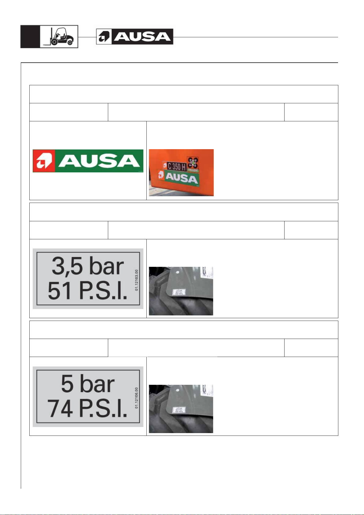
FRONT AXLE WHEELS INFLATED PRESSURE (modelos C350H / C350HI / C350H x4 / C350HI x4)
REFERENCE: DESCRIPTION: QUANTITY:
01.12103.00 INDICATIVE STICKER 3,5 BAR / 51 PSI 2
POSITION:
On both sides of the machine, above the fenders of the front wheels, at the front
outer end of the fenders, aligned with the outer edge.
STICKER:
FRONT AXLE WHEELS INFLATED PRESSURE (modelos C300H / C300HI / C300H x4 / C300HI x4)
REFERENCE: DESCRIPTION: QUANTITY:
01.12106.00 INDICATIVE STICKER 5 BAR / 74 PSI 2
POSITION:
On both sides of the machine, above the fenders of the front wheels, at the front
outer end of the fenders, aligned with the outer edge.

C300H / C300HI / C300H x4 / C300HI x4
C350H / C350HI / C350H x4 / C350HI x4
Decals / labels / identification plates all markets (except USA)
STICKER:
REAR AXLE WHEELS INFLATED PRESSURE (C300H x4 / C350H x4 / C350HI x4)
REFERENCE: DESCRIPTION: QUANTITY:
01.12106.00 INDICATIVE STICKER 5 BAR / 74 PSI 2
POSITION:
On both sides of the machine, on top of the vertical face, in the upper rear
position of each tank, aligned with the bottom of the tank.
43
STICKER:
REAR AXLE WHEELS INFLATED PRESSURE (C300HI x4)
REFERENCE: DESCRIPTION: QUANTITY:
32.12102.00 INDICATIVE STICKER 6 BAR / 89 PSI 2
POSITION:
On both sides of the machine, on top of the vertical face, in the upper rear
position of each tank, aligned with the bottom of the tank.
STICKER:
REAR AXLE WHEELS INFLATED PRESSURE (C300H / C300HI / C350H / C350HI x4)
REFERENCE: DESCRIPTION: QUANTITY:
01.12107.01 INDICATIVE STICKER 6,5 BAR / 96 PSI 2
POSITION:
On both sides of the machine, on top of the vertical face, in the upper rear
position of each tank, aligned with the bottom of the tank.

C300H / C300HI / C300H x4 / C300HI x4
C350H / C350HI / C350H x4 / C350HI x4
44
Decals / labels / identification plates all markets (except USA)
STICKER:
FUEL TYPE INDICATION
REFERENCE: DESCRIPTION: QUANTITY:
43.01356.00 INDICATIVE STICKER 90x45 FUEL 1
POSITION:
On the right tank of the machine, next to the fuel cap, aligned with the vertical
outer wall of the tank.
STICKER:
EC INDICATION
REFERENCE: DESCRIPTION: QUANTITY:
45.19101.00 INDICATIVE STICKER 70x70 2
POSITION:
On the left side of the machine, at the bottom inner side of the front fenders,
aligned on its upper side with mark id 58.01353.01 “To hoist machine”.
STICKER:
HYDRAULIC OIL TYPE
REFERENCE: DESCRIPTION: QUANTITY:
43.01352.20 INDICATIVE STICKER 70x32 HYDRAULIC OIL 1
POSITION:
On the left-hand side tank, below the filler cap, aligned with the inner edge of the
tank, and centered with the cap.

C300H / C300HI / C300H x4 / C300HI x4
C350H / C350HI / C350H x4 / C350HI x4
Decals / labels / identification plates all markets (except USA)
STICKER:
ENGINE OIL TYPE
REFERENCE: DESCRIPTION: QUANTITY:
43.01170.02 INDICATIVE STICKER 90x45 1
POSITION:
On the inner cab lock, easily legible with the cab raised.
45
STICKER:
MACHINE MODEL INDICATION (C300H - C300H x4 )
REFERENCE: DESCRIPTION: QUANTITY:
57.12001.00 INDICATIVE STICKER 68x267 MODEL C300H / HI 2
POSITION:
On both sides of the machine, at a distance of 0.984 in and a height of 5.906
in from the lower rear corner of each tank, aligned with the bottom of the tank.
STICKER:
MACHINE MODEL INDICATION (C350H - C350H x4 )
REFERENCE: DESCRIPTION: QUANTITY:
57.12002.00 INDICATIVE STICKER 68x267 MODEL C350H / HI 2
POSITION:
On both sides of the machine, at a distance of 1.969 in and a height of 5.906
in from the lower rear corner of each tank, aligned with the bottom of the tank.

C300H / C300HI / C300H x4 / C300HI x4
C350H / C350HI / C350H x4 / C350HI x4
46
Decals / labels / identification plates all markets (except USA)
STICKER:
CHARACTERISTICS PLATE
REFERENCE: DESCRIPTION: QUANTITY:
01.00779.26 PLATE CHARACTERISTICS 100x130 1
POSITION:
Riveted on top of the engine bulkhead, on its rear upper left-hand side (in
forward direction of machine), in the holes prepared. Etched according to
assembly instruction.
STICKER:
AUSA ANAGRAM
REFERENCE: DESCRIPTION: QUANTITY:
46.08099.00 AUSA ANAGRAM 1
POSITION:
Embedded in the cab front panel, on its outer side, in the upper left-hand part
(in forward direction of machine).
STICKER:
WARNING IN CASE OF OVERTURNING THE MACHINE
REFERENCE: DESCRIPTION: QUANTITY:
12.12010.00 SAFETY STICKER 1
POSITION:
Top left-hand corner of the dashboard, under sticker ref. 02.00774.00 “Do not
use” and aligned with this on its left side.
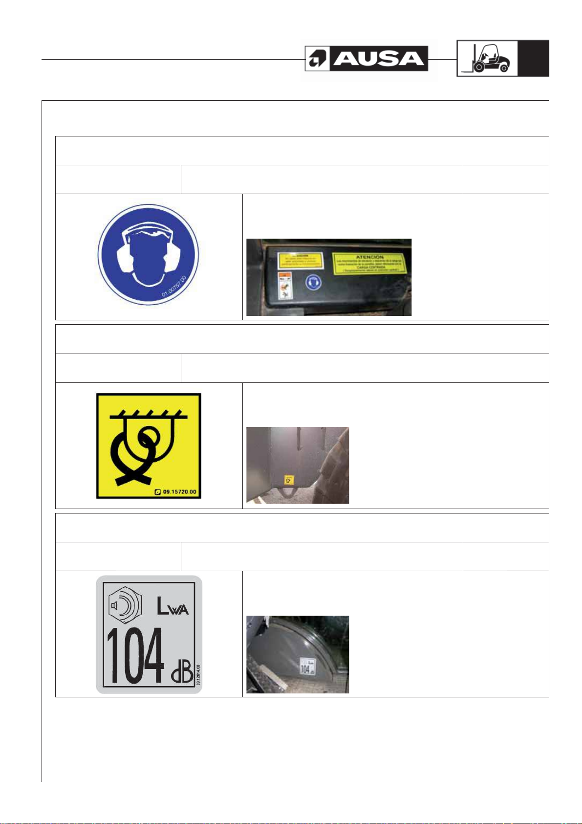
C300H / C300HI / C300H x4 / C300HI x4
C350H / C350HI / C350H x4 / C350HI x4
Decals / labels / identification plates all markets (except USA)
STICKER:
ACOUSTIC OPERATOR PROTECTION
REFERENCE: DESCRIPTION: QUANTITY:
01.00757.00 INDICATIVE STICKER D40 1
POSITION:
Top left-hand corner of the instrument panel, under sticker 02.00774.00 “Do not
use”, aligned with this on its right side and centered with sticker ref. 12.12010.00.
47
STICKER:
POINT HOISTED MACHINE
REFERENCE: DESCRIPTION: QUANTITY:
09.15720.00 INDICATIVE STICKER 35x35 4
POSITION:
Above each of the four eyebolts at the bottom of the frame for lifting the machine.
STICKER:
MAXIMUM SOUND LEVEL
REFERENCE: DESCRIPTION: QUANTITY:
09.12014.00 STICKER NOISE 104 DB 1
POSITION:
On the inside of the right front wheel arch, aligned with the cab floor.

C300H / C300HI / C300H x4 / C300HI x4
C350H / C350HI / C350H x4 / C350HI x4
48
Decals / labels / identification plates all markets (except USA)
STICKER:
FullGrip® System
REFERENCE: DESCRIPTION: QUANTITY:
43.00397.00 INDICATIVE STICKER 110x110 2
POSITION:
On both sides of the machine, next to the AUSA sticker (ref. 13.12136.00) and
aligned on the right side.
STICKER:
MAST TILTING FORWARD MARKER (MACHINES WITH SEMI-CLOSED AND FULL CAB)
REFERENCE: DESCRIPTION: QUANTITY:
57.12010.00 INDICATIVE STICKER LOWERING MAST 1
POSITION:
Into the cabin, on the left side of the engine’s cover next to the handle that
releases the cabin latch.
STICKER:
NON MOVEMENTS WITH LOAD OFFCENTERED (MASTS OF MORE THAN 3,7M / 12ft 2 in)
REFERENCE: DESCRIPTION: QUANTITY:
43.02187.02 INDICATIVE STICKER 70x210 ENGLISH 1
POSITION:
In the upper part of the dashboard, next to the sticker ref. 02.00777.00 “Do not
use” aligned with this on its upper side.
* In heated enclosed cab, position at the bottom left-hand side of the window
0.3937 in away from the edge (bottom left side).
*
Heated cab

C300H / C300HI / C300H x4 / C300HI x4
C350H / C350HI / C350H x4 / C350HI x4
Decals / labels / identification plates all markets (except USA)
STICKER:
AUSA STICKER
REFERENCE: DESCRIPTION: QUANTITY:
13.12136.00 AUSA STICKER 2
POSITION:
On both sides of the mast, above the beam, with its lower side aligned at 4ft 95
in from the ground, above the sticker ref. 45.01352.00 “Dangerous area”, and
0.3937 in away from it.
49
STICKER:
INDICATION TRANSFER BOX OIL.
REFERENCE: DESCRIPTION: QUANTITY:
43.00396.02 INDICATIVE STICKER 60x95 1
POSITION:
Into the engine compartment on the external face of the joystick control valve
support, above “Brake fluid indication” sticker.
STICKER:
NOT USE WITHOUT AUTHORIZATION
REFERENCE: DESCRIPTION: QUANTITY:
02.00777.00 INDICATIVE STICKER 50x120 ENGLISH 1
POSITION:
Top left-hand corner of the dashboard, aligned on its left side with sticker nº
12.12010.00 “Safety warning”.

C300H / C300HI / C300H x4 / C300HI x4
C350H / C350HI / C350H x4 / C350HI x4
50
Decals / labels / identification plates all markets (except USA)
STICKER:
BRAKE FLUID INDICATION
REFERENCE: DESCRIPTION: QUANTITY:
43.70780.01 INDICATIVE STICKER 60x100 BRAKE 1
POSITION:
Into the engine compartment on the external face of the joystick control valve
support, below “Transfer box oil” sticker.
STICKER:
HOT PARTS INDICATION
REFERENCE: DESCRIPTION: QUANTITY:
02.00765.00 INDICATIVE STICKER 40x80 ENGLISH 1
POSITION:
Inside the counterweight, near the exhaust manifold, easily readable when trying
to work on the engine.
STICKER:
LOAD CHART PLATE
REFERENCE: DESCRIPTION: QUANTITY:
43.01350.28 / 30.12004.00 INDICATIVE PLATE 91x156 LOAD CHARTS 1
POSITION:
Riveting in 4 holes provided, in the central outer part the left-hand front fender.
MOD.
C300H / C300H x4
CARGA MAXIMA EN TERRENO HORIZONTAL
CHARGE ADMISSIBLE EN PALIER
PERMISSIBLE LOAD ON LEVEL
MAX. ZULAESSIGE LAST BEI EBENEM BODEN
3000
G kgs
2771
2574
2404
G
D
D cm.
AUSA Center, S.L.U.
08243 MANRESA (ESPAÑA)
2255
2123
3,3
50 60 70 80 90 100 110 120
43.01350.20
2005
1900
Etched according to assembly instruction.
* Add another unit at the top in the event of installing a mast higher than 12ft 14 in.

C300H / C300HI / C300H x4 / C300HI x4
C350H / C350HI / C350H x4 / C350HI x4
Decals / labels / identification plates all markets (USA Market)
STICKER:
JOYSTICK FUNCTION. SUBSTITUTE REF. 10.15003.01
REFERENCE: DESCRIPTION: QUANTITY:
10.15006.01 INDICATIVE STICKER 60X75 1
POSITION:
Stuck on the inside of the right front fender, in the top center position. Just above
sticker ref. 10.15008.01, at 0.1969 in.
51
STICKER:
JOYSTICK FUNCTION . SUBSTITUTE REF. 10.15005.01
REFERENCE: DESCRIPTION: QUANTITY:
10.15008.01 INDICATIVE STICKER MAST SIDE-SHIFT (USA) 1
POSITION:
Stuck on the inside of the right front fender, in the top center position. Just above
sticker ref. 10.15006.01, at 0.1969 in.
STICKER:
JOYSTICK FUNCTION BUTTONS
REFERENCE: DESCRIPTION: QUANTITY:
10.15009.00
INDICATIVE STICKER AUXILIAR HYDRAULIC LINE ()
POSITION:
Stuck on the inside of the right front fender, in the top center position. Just above
sticker ref. 10.15005.01, at 0.1969 in.
1

C300H / C300HI / C300H x4 / C300HI x4
C350H / C350HI / C350H x4 / C350HI x4
52
Decals / labels / identification plates all markets (USA Market)
STICKER:
JOYSTICK FUNCTION BUTTONS
REFERENCE: DESCRIPTION: QUANTITY:
10.15011.00
INDICATIVE STICKER 4WD CONNECTION ()
POSITION:
Stuck on the inside of the right front fender, in the top center position. Just above
sticker ref. 10.15005.01 o 10.15009.00, at 0.1969 in.
1
STICKER:
DANGEROUS AREA.. SUBSTITUTE REF. 45.01352.00
REFERENCE: DESCRIPTION: QUANTITY:
45.01352.01 INDICATIVE STICKER 2
POSITION:
On both sides of the mast, above the beam, with its upper side aligned at 4ft 92
in from the ground, below the sticker ref. 13.12136.00 “AUSA Make”, and 0.3937
in away from it.
STICKER:
TO HOIST MACHINE
REFERENCE: DESCRIPTION: QUANTITY:
58.01353.01 INDICATIVE STICKER 105X100 2
POSITION:
On the left side of the machine, at the lower exterior part of the front fender,
aligned on its upper side with sticker 45.19101.00 “EC mark”.

C300H / C300HI / C300H x4 / C300HI x4
C350H / C350HI / C350H x4 / C350HI x4
Decals / labels / identification plates all markets (USA Market)
STICKER:
AUSA
REFERENCE: DESCRIPTION: QUANTITY:
13.12136.00 AUSA STICKER 2
POSITION:
On both sides of the machine, at a distance of 0.984 in and a height of 1.969
in from the lower rear corner of each tank, aligned with the bottom of the tank.
53
STICKER:
FRONT AXLE WHEELS INFLATED PRESSURE (modelos C350H / C350HI / C350H x4 / C350HI x4)
REFERENCE: DESCRIPTION: QUANTITY:
01.12103.00 INDICATIVE STICKER 3,5 BAR / 51 PSI 2
POSITION:
On both sides of the machine, above the fenders of the front wheels, at the front
outer end of the fenders, aligned with the outer edge.
STICKER:
FRONT AXLE WHEELS INFLATED PRESSURE (modelos C300H / C300HI / C300H x4 / C300HI x4)
REFERENCE: DESCRIPTION: QUANTITY:
01.12106.00 INDICATIVE STICKER 5 BAR / 74 PSI 2
POSITION:
On both sides of the machine, above the fenders of the front wheels, at the front
outer end of the fenders, aligned with the outer edge.

C300H / C300HI / C300H x4 / C300HI x4
C350H / C350HI / C350H x4 / C350HI x4
54
Decals / labels / identification plates all markets (USA Market)
STICKER:
REAR AXLE WHEELS INFLATED PRESSURE (C300H x4 / C350H x4 / C350HI x4)
REFERENCE: DESCRIPTION: QUANTITY:
01.12106.00 INDICATIVE STICKER 5 BAR / 74 PSI 2
POSITION:
On both sides of the machine, on top of the vertical face, in the upper rear
position of each tank, aligned with the bottom of the tank.
STICKER:
REAR AXLE WHEELS INFLATED PRESSURE (C300HI x4)
REFERENCE: DESCRIPTION: QUANTITY:
32.12102.00 INDICATIVE STICKER 6 BAR / 89 PSI 2
POSITION:
On both sides of the machine, on top of the vertical face, in the upper rear
position of each tank, aligned with the bottom of the tank.
STICKER:
REAR AXLE WHEELS INFLATED PRESSURE (C300H / C300HI / C350H / C350HI x4)
REFERENCE: DESCRIPTION: QUANTITY:
01.12107.01 INDICATIVE STICKER 6,5 BAR / 96 PSI 2
POSITION:
On both sides of the machine, on top of the vertical face, in the upper rear
position of each tank, aligned with the bottom of the tank.

C300H / C300HI / C300H x4 / C300HI x4
C350H / C350HI / C350H x4 / C350HI x4
Decals / labels / identification plates all markets (USA Market)
STICKER:
FUEL TYPE INDICATION
REFERENCE: DESCRIPTION: QUANTITY:
43.01356.00 INDICATIVE STICKER 90x45 FUEL 1
POSITION:
On the right tank of the machine, next to the fuel cap, aligned with the vertical
outer wall of the tank.
55
STICKER:
HYDRAULIC OIL TYPE (USA). SUBSTITUTE REF. 43.01352.20
REFERENCE: DESCRIPTION: QUANTITY:
60.01352.01 INDICATIVE STICKER 70x32 HYDRAULIC OIL 1
POSITION:
On the left-hand side tank, below the filler cap, aligned with the inner edge of the
tank, and centered with the cap.
STICKER:
ENGINE OIL TYPE. SUBSTITUTE REF. 43.01170.02
REFERENCE: DESCRIPTION: QUANTITY:
43.01170.03 INDICATIVE STICKER 90x45 1
POSITION:
On the inner cab lock, easily legible with the cab raised.

C300H / C300HI / C300H x4 / C300HI x4
C350H / C350HI / C350H x4 / C350HI x4
56
Decals / labels / identification plates all markets (USA Market)
STICKER:
MACHINE MODEL INDICATION (C300H - C300H x4 )
REFERENCE: DESCRIPTION: QUANTITY:
57.12001.00 INDICATIVE STICKER 68x267 2
POSITION:
On both sides of the machine, at a distance of 0.984 in and a height of 5.906
in from the lower rear corner of each tank, aligned with the bottom of the tank.
STICKER:
MACHINE MODEL INDICATION (C350H - C350H x4 )
REFERENCE: DESCRIPTION: QUANTITY:
57.12002.00 INDICATIVE STICKER 68x267 MODEL C350H / HI 2
POSITION:
On both sides of the machine, at a distance of 1.969 in and a height of 5.906
in from the lower rear corner of each tank, aligned with the bottom of the tank.
STICKER:
CHARACTERISTICS PLATE. SUBSTITUTE 01.00779.26
REFERENCE: DESCRIPTION: QUANTITY:
01.00779.23 PLATE CHARACTERISTICS 100x130 1
POSITION:
Riveted on top of the engine bulkhead, on its rear upper left-hand side (in
forward direction of machine), in the holes prepared. Etched according to
assembly instruction.

C300H / C300HI / C300H x4 / C300HI x4
C350H / C350HI / C350H x4 / C350HI x4
Decals / labels / identification plates all markets (USA Market)
STICKER:
AUSA ANAGRAM
REFERENCE: DESCRIPTION: QUANTITY:
46.08099.00 AUSA ANAGRAM 1
POSITION:
Embedded in the cab front panel, on its outer side, in the upper left-hand part
(in forward direction of machine).
57
STICKER:
WARNING IN CASE OF OVERTURNING THE MACHINE
REFERENCE: DESCRIPTION: QUANTITY:
12.12010.00 SAFETY STICKER 1
POSITION:
Top left-hand corner of the dashboard, under sticker ref. 02.00774.00 “Do not
use” and aligned with this on its left side.
STICKER:
ACOUSTIC OPERATOR PROTECTION
REFERENCE: DESCRIPTION: QUANTITY:
01.00757.00 INDICATIVE STICKER D40 1
POSITION:
Top left-hand corner of the instrument panel, under sticker 02.00774.00 “Do not
use”, aligned with this on its right side and centered with sticker ref. 12.12010.00.

C300H / C300HI / C300H x4 / C300HI x4
C350H / C350HI / C350H x4 / C350HI x4
58
Decals / labels / identification plates all markets (USA Market)
STICKER:
POINT HOISTED MACHINE
REFERENCE: DESCRIPTION: QUANTITY:
09.15720.00 INDICATIVE STICKER 35x35 4
POSITION:
Above each of the four eyebolts at the bottom of the frame for lifting the machine.
STICKER:
MAXIMUM SOUND LEVEL
REFERENCE: DESCRIPTION: QUANTITY:
09.12014.00 STICKER NOISE 104 DB 1
POSITION:
On the inside of the right front wheel arch, aligned with the cab floor.
STICKER:
FullGrip® System
REFERENCE: DESCRIPTION: QUANTITY:
43.00397.00 INDICATIVE STICKER 110x110 2
POSITION:
On both sides of the machine, next to the AUSA sticker (ref. 13.12136.00) and
aligned on the right side.

C300H / C300HI / C300H x4 / C300HI x4
C350H / C350HI / C350H x4 / C350HI x4
Decals / labels / identification plates all markets (USA Market)
STICKER:
MAST TILTING FORWARD MARKER (MACHINES WITH SEMI-CLOSED AND FULL CAB)
REFERENCE: DESCRIPTION: QUANTITY:
57.12010.00 INDICATIVE STICKER LOWERING MAST 1
POSITION:
Into the cabin, on the left side of the engine’s cover next to the handle that
releases the cabin latch.
59
STICKER:
NON MOVEMENTS WITH LOAD OFFCENTERED (MASTS OF MORE THAN 3,7M / 12ft 2 in)
REFERENCE: DESCRIPTION: QUANTITY:
43.02187.02 INDICATIVE STICKER 70x210 ENGLISH 1
POSITION:
In the upper part of the dashboard, next to the sticker ref. 02.00777.00 “Do not
use” aligned with this on its upper side.
* In heated enclosed cab, position at the bottom left-hand side of the window
0.3937 in away from the edge (bottom left side).
*
Heated cab

C300H / C300HI / C300H x4 / C300HI x4
C350H / C350HI / C350H x4 / C350HI x4
60
Decals / labels / identification plates all markets (USA Market)
STICKER:
AUSA STICKER
REFERENCE: DESCRIPTION: QUANTITY:
13.12136.00 AUSA STICKER 2
POSITION:
On both sides of the mast, above the beam, with its lower side aligned at 4ft 95
in from the ground, above the sticker ref. 45.01352.00 “Dangerous area”, and
0.3937 in away from it.
STICKER:
INDICATION TRANSFER BOX OIL.
REFERENCE: DESCRIPTION: QUANTITY:
43.00396.02 INDICATIVE STICKER 60x95 1
POSITION:
Into the engine compartment on the external face of the joystick control valve
support, above “Brake fluid indication” sticker.
STICKER:
NOT USE WITHOUT AUTHORIZATION. SUBSTITUTE REF. 02.00777.00
REFERENCE: DESCRIPTION: QUANTITY:
02.00777.04 INDICATIVE STICKER 50x120 1
POSITION:
On top of the vertical face of the engine cover, easily readable before accessing
the forklift, aligned with the cab floor.

C300H / C300HI / C300H x4 / C300HI x4
C350H / C350HI / C350H x4 / C350HI x4
Decals / labels / identification plates all markets (USA Market)
STICKER:
BRAKE FLUID INDICATION
REFERENCE: DESCRIPTION: QUANTITY:
43.70780.01 INDICATIVE STICKER 60x100 BRAKE 1
POSITION:
Into the engine compartment on the external face of the joystick control valve
support, below “Transfer box oil” sticker.
61
STICKER:
HOT PARTS INDICATION
REFERENCE: DESCRIPTION: QUANTITY:
02.00765.00 INDICATIVE STICKER 40x80 ENGLISH 1
POSITION:
Inside the counterweight, near the exhaust manifold, easily readable when trying
to work on the engine.
STICKER:
LOAD CHART PLATE
REFERENCE: DESCRIPTION: QUANTITY:
43.01350.28 / 30.12004.00 INDICATIVE PLATE 91x156 LOAD CHARTS 1
POSITION:
Riveting in 4 holes provided, in the central outer part the left-hand front fender.
MOD.
C300H / C300H x4
CARGA MAXIMA EN TERRENO HORIZONTAL
CHARGE ADMISSIBLE EN PALIER
PERMISSIBLE LOAD ON LEVEL
MAX. ZULAESSIGE LAST BEI EBENEM BODEN
3000
G kgs
2771
2574
2404
G
D
D cm.
AUSA Center, S.L.U.
08243 MANRESA (ESPAÑA)
2255
2123
3,3
50 60 70 80 90 100 110 120
43.01350.20
2005
1900
Etched according to assembly instruction.
* Add another unit at the top in the event of installing a mast higher than 12ft 14 in.

C300H / C300HI / C300H x4 / C300HI x4
C350H / C350HI / C350H x4 / C350HI x4
62
Decals / labels / identification plates all markets (USA Market)
STICKER:
REFLECTIVE TRIANGLE WITH PLATE. (MACHINE WITH OPEN CAB) (USA)
REFERENCE: DESCRIPTION: QUANTITY:
10.15120.00 INDICATIVE STICKER 350x400 1
POSITION:
Fixed at the bottom edge of the cab rear opening, centered horizontally, aligned
with the lower edge of the cab opening.
STICKER:
REFLECTIVE TRIANGLE (MACHINES WITH SEMI-CLOSED AND FULL CAB)) (USA)
REFERENCE: DESCRIPTION: QUANTITY:
10.15122.00 INDICATIVE STICKER 356x356 1
POSITION:
On the cab rear window, centered horizontally on the glass, aligned with the
lower edge 0.3937 in away from it.
STICKER:
NOT TO TOUCH INDICATION
REFERENCE: DESCRIPTION: QUANTITY:
02.00766.00 INDICATIVE STICKER 40x80 USA 1
POSITION:
On the top of the radiator fan guard.

C300H / C300HI / C300H x4 / C300HI x4
C350H / C350HI / C350H x4 / C350HI x4
Decals / labels / identification plates all markets (USA Market)
STICKER:
PROTECTION STRUCTURE INDICATION
REFERENCE: DESCRIPTION: QUANTITY:
10.01414.01 INDICATIVE STICKER 60x125 USA 1
POSITION:
In the upper left-hand corner of the dashboard, aligned at the left with the
adhesive ref. 10.01414.01 “Warning Security”.
63
STICKER:
CALIFORNIA INDICATION (USA)
REFERENCE: DESCRIPTION: QUANTITY:
43.01171.00 INDICATIVE STICKER 42x77 1
POSITION:
In the upper right-hand corner of the dashboard, aligned at the top with the
bend in the dashboard.

64
C300H / C300HI / C300H x4 / C300HI x4
C350H / C350HI / C350H x4 / C350HI x4
Controls
and instruments
Pedals (fig. 1)
a- Inching pedal.
When the pedal is depressed the machine stops, allowing the engine to accelerate
for faster operation of the mast. When the pedal is slowly released the machine will
start to move again.
WARNING
The inching pedal also acts on the parking brake when it is kept fully depressed.
b- Service brake pedal.
Acts on a pump located below the pedal.
c- Accelerator pedal.
Acts on the engine through a cable
Emergency brake
In the event of emergency use the inching pedal.
Parking brake (fig. 2)
The parking brake is operated electronically using the switch (d). It is also operated
electronically when the inching pedal is kept fully depressed.
a b c
d
Joystick (fig. 3)
Forward and backward directional travel control (FNR control)
The direction of travel is changed using the electric switch (e) located on the lower part
of the joystick. In each case the corresponding arrow showing the direction of travel
lights up.
When the direction arrows are not lit, the direction of travel control is at the stop position
(neutral). By pressing the front of the switch the machine travels forwards and by
pressing the rear of the switch the machine travels backwards.
Safety: When the parking brake is not on and/or the operator is not sitting in the driver’s
(fig. 1)
seat, the direction arrows are also switched off and the direction of travel control is
disconnected.
Back-up alarm
It sounds when reverse is selected.
WARNING
If the forklift is equipped with lighting, the back-up alarm is disconnected when
the lights are switched on. However, the rear white reversing lights continue to
(fig. 2)
work.
e
(fig. 3)

C300H / C300HI / C300H x4 / C300HI x4
C350H / C350HI / C350H x4 / C350HI x4
65
Controls
and instruments
Horn (fig. 1, 2)
C300H / C300HI / C350H / C350HI
The horn is operated using the button (f) located on the right of the joystick.
C300H x4 / C300HI x4 / C350H x4 / C350HI x4
The horn is operated using the button (g) located on the upper right switch of the
instrument panel.
4x4 connection (FullGrip® System) (fig.3)
Connecting the 4x4
The 4x4 connects by pressing yellow switch (i) located underneath the joystick at the
right side.
Disconnecting the 4x4
The 4x4 disconnects just leaving yellow switch (i) on its rest position.
CAUTION
f
6
h
Do not connect the 4x4 traction at high speed
REMARK: Moreover, some models may differ from (fig. 3) and assemble a plastic
plug instead of red switch (h).
5
g
(fig. 2)(fig. 3) (fig. 1)
i
h

66
C300H / C300HI / C300H x4 / C300HI x4
C350H / C350HI / C350H x4 / C350HI x4
Controls
and instruments
Load handling controls (fig. 1)
The mast and the load are moved by using the joystick.
Raising and lowering the mast.
If the joystick is pulled backwards the mast and the forks lift and if pushed forwards the
mast and the forks lower.
Tilting the forks.
If the joystick is pulled to the left, the mast forks tilt backwards (forks lift) and if pushed
to the right, they tilt forward (forks lower).
Side-shift (fig. 2).
By holding down button (5) on the joystick and pulling the joystick to the left, the forks
move to the left.
By holding down button (5) and pushing the joystick to the right the forks move to the
right.
Always centre the carriage when in transit or when transporting a load.
Additional hydraulic control for attachments () (fig. 3).
By holding down button (6) of the joystick and pulling it to the left (towards the operator),
or pushing it to the right, pressure is supplied to the quick hydraulic
WARNING
The fork positioner allows the operator to set the forks with a variable gap
matching different pallet size without removing the forks manually.
Be aware this attachment is NOT foreseen for lateral pushing operation (similar
to an hydraulic clamp).
This type of operation is forbidden, it could be dangerous for the persons and
it is considered a misuse, consequently, the manufacturer does not accept any
claim for damages caused in this way.
(fig. 3) (fig. 2) (fig. 1)

C300H / C300HI / C300H x4 / C300HI x4
C350H / C350HI / C350H x4 / C350HI x4
67
Instrument Panel
and controls
Starter switch (fig. 1)
See section STARTING THE ENGINE
a- In this position the ignition and the engine are disconnected.
b- Ignition on. The engine pre-heating system and the lamp on the control panel are
activated for a few seconds.
c- Starter. Turning the key to position (c) starts the engine.
Before re-starting the engine, the key should first be switched to position (a).
Fuse box (fig. 2)
This is located at the right of the steering column, next to the starter switch.
See the section ELECTRIC CIRCUIT in this Operator’s and Safety Manual to identify
the number and function of each fuse.
b
a
c
(fig. 2) (fig. 1)

68
Instrument Panel
and controls
C300H / C300HI / C300H x4 / C300HI x4
C350H / C350HI / C350H x4 / C350HI x4
NOTE
For ease of understanding, the picture shows the panel with the steering wheel
removed.
C300H / C300HI / C350H / C350HI instrument panel: Components and
Operation (fig. 1)
1- Multi-function instrument. See the section Multi-function instrument.
2- Light switch. This switch has two positions, the first switches on the low beam
and the second switches on the high beam.
3- Heating switch (). This has two positions to give two fan speeds.
4- Working light switch (). To connect the front lights switch turn on the switch.
5- Parking brake. To activate the forklift parking brake, press the switch.
6- Windscreen wiper switch (). To switch on the windscreen wiper, press the
switch. To activate the windscreen wiper washer pump, press the same switch
again.
7- Rotating beacon switch. To switch on, press the button and it will light up. To
switch off, press the button again.
8- Indicators switch (). The turning indicators are switched on by pressing the
switch to the left or to the right.
9- Hazard lights switch (). To switch on, press the button and it will blink. To
switch off, press the button again.
(fig. 1)
1 2
3
4
789
6
5

C300H / C300HI / C300H x4 / C300HI x4
C350H / C350HI / C350H x4 / C350HI x4
69
Instrument Panel
and controls
C300H x4 / C300HI x4 / C350H x4 / C350HI x4 instrument panel ():
Components and Operation (fig. 1)
1- Multi-function instrument. See the section Multi-function instrument.
2- Light switch. This switch has two positions, the first switches on the low beam
and the second switches on the high beam.
3- Heating switch (). This has two positions to give two fan speeds.
4- Horn switch. To activate the horn, press the switch.
5- Parking brake. To activate the forklift parking brake, press the switch.
6- Windscreen wiper switch (). To switch on the windscreen wiper, press the
switch. To activate the windscreen wiper washer pump, press the same switch
again.
7- Rotating beacon switch. To switch on, press the button and it will light up. To
switch off, press the button again.
8- Indicators switch (). The turning indicators are switched on by pressing the
switch to the left or to the right.
9- Working light switch (). To connect the front lights switch turn on the switch.
10- Hazard lights switch (). To switch on, press the button and it will blink. To
switch off, press the button again.
(fig. 1)
1
2 3 4
10 9 8 7 6 5

70
C300H / C300HI / C300H x4 / C300HI x4
C350H / C350HI / C350H x4 / C350HI x4
Instrument Panel
and controls
Multifunction instrument (fig. 1)
(fig. 1)
A- Hourmeter. This gauge indicates the total running time of the forklift engine to
enable servicing of the engine at proper intervals. (See MAINTENANCE CHART
for servicing frequency).
B- Fuel level. This gauge indicates the diesel fuel level in the tank.
C- Fuel reserve indicator lamp. This lights up when the level of fuel in the tank falls
into reserve.
D- Air filter warning lamp. When the air filter of the diesel engine becomes clogged
with dirt, this lamp will light. The air filter should be immediately cleaned or serviced.
E- Engine pre-heat indicator lamp. When this lamp glows it indicates that the
engine pre-heat plugs are in operation and heating the combustion chamber the
temperature required to start the engine.
F- Hydraulic oil level warning lamp. This lights up and emits an audible warning
when the hydraulic oil level is at the minimum level. Oil should be added to top up
the level to the correct level
G- Engine oil pressure warning lamp. When the ignition is on, this lamp lit and
turns off when the engine is running. If this lamp turns on emits an audible warning
while the engine is running, the engine must be stopped immediately to prevent
damages. Check the level and add oil if necessary.
H- Battery charge warning lamp. This lamp shows the condition of the battery
and indicates if the battery charge is too low or if the alternator is not charging properly.
Once the engine starts to run, this red lamp turns off If it remains lit, stop the engine
and determine the cause.
I- Engine temperature warning lamp. This gauge shows the temperature of
the coolant in the engine cooling system. When this lamp glows emits an audible
warning means that the engine is operating at high temperature which could
damage the engine. The engine should be stopped immediately to determine the
cause of the high temperature. It could be low coolant, debris in the radiator or a
thermostat, which does not operate correctly.
J- No application in this model
K- High beam indicator lamp (with lighting equipment) (). This lamp is lit
when high beams are selected.
L- Turn signal indicator lamp (with lighting equipment) (). This lamp will
blink indicating turn signals are operating.

C300H / C300HI / C300H x4 / C300HI x4
C350H / C350HI / C350H x4 / C350HI x4
71
Instrument Panel
and controls
Fuel
The current regulations of exhaust emissions, require that, for the whole life of the
machine, the level on the different components of these emissions, are under the
maximum figures stated on the regulations.
As a consequence of that, the maintenance plan of the engine has to be followed up
carefully, giving special attention to the quality and pureness of the fuel, the cleanliness
of the filters and, in general, to the general maintenance of the fuel circuit.
Handling
- Only use the fuel type authorized by AUSA. Do not use fuel mixed with oil, other
fuels or unsuitable additives.
- The correct fuel for the forklift is diesel. For further details regarding fuel type and
required specifications see the section FLUIDS AND LUBRICANTS.
- Do not allow the fuel to come into contact with the skin and avoid inhaling the
fumes, which are toxic. High concentrations of fuel vapour may cause sickness,
loss of consciousness or even loss of life in the event of prolonged exposure.
If you experience symptoms such as sickness or loss of consciousness seek
medical advice immediately.
- Do not store fuel in closed places. The fuel vapours will alter the atmosphere of
the enclosure and may cause a fire or explosion.
- Use suitable impermeable clothing, safety glasses and gloves when handling
fuel. When refuelling from a tank, bucket or barrel using a siphon, the following
precautions should be taken.
- If refuelling is by gravity, from a raised tank, open the fuel output valve of the tank
slowly.
- If the tank or barrel does not have an output valve use a suitable vacuum pump.
WARNING
Never suck the fuel into the pipe by mouth to start the siphoning. Fuel and its
vapours are highly toxic.
- In the event of fuel spillage, please inform the supervisor, mark the area suitably
and cover the spillage with absorbent material.
- Take suitable measures to avoid risk until the remains of the fuel have been
completely removed.

72
C300H / C300HI / C300H x4 / C300HI x4
C350H / C350HI / C350H x4 / C350HI x4
Instrument Panel
and controls
Refuelling
WARNING
Smoking, naked flames or sparks are not permitted in the refuelling area. Fuel
vapours can be explosive.
- Refuel in a well-ventilated area.
- Position the forklift as close as possible to the fuel pump so that the filler hose
reaches the opening of the tank comfortably.
- Apply the parking brake, switch off the engine and lights, including the rotating
beacon.
NOTE
If the fuel pump is equipped with a vehicle earth connection, connect this to a
non-isolated metal component of the forklift.
- Clean the fuel cap and surrounding area with a cloth if they have been dirtied. Do
not allow dust, water, or any other substance to enter the tank.
- Open the fuel cap using the key and turning to the left.
- Fill the tank without exceeding the volume specified for the forklift. Take care not
to spill fuel outside the tank. If you do, clean immediately and dry the surface well.
- Close the tank using the key and remove it from the cap. Check that the cap is
correctly closed.

C300H / C300HI / C300H x4 / C300HI x4
C350H / C350HI / C350H x4 / C350HI x4
Operating
the forklift
(fig. 1)
73
WARNING
Before each period of operation, check the forklift for correct operation of the
steering, brakes, hydraulic controls, instruments and safety equipment. Check
the neutral position of the FNR switch. A machine that runs correctly is more
efficient and can prevent accidents. Make all necessary adjustments or repairs
before you operate the machine.
Entering and leaving the operator cabin (fig. 1)
Don’t hold and pull of the steering wheel to come in/out the forklift, use the handles
located on the overhead guard and always place your foot on the rough bands of the
step, to prevent any downfall when you come in or come out.
Standard seat adjustment (fig. 2, 3, 4)
Each day, before operating the dumper, adjust your seat to a position in which you feel
comfortable.
Pull the lever (a) to up to unlock the seat. Slide the seat forward or backwards to reach
the desired position.
Releasing the leaver the seat locks.
The damping of the seat can be adjusted between 50 and 130 Kg, depending upon
the operator’s weight; to do so turn knob (b) clockwise or counter-clockwise in order to
adjust properly the seat damping.
For correct adjustment of the damping, with the operator sitting the needle (c) should
remain within the range of green scale into the gauge.
Using the lever (d) located on the left side of the seat backrest, the backrest inclination
can be changed. Pulling down the lever the backrest unlocks. Adjust the backrest and
release the leaver to lock again.
Ensure that you fasten your seatbelt.
a
b
c
d
(fi g. 4) (fi g. 3) (fi g. 2)

74
C300H / C300HI / C300H x4 / C300HI x4
C350H / C350HI / C350H x4 / C350HI x4
Operating
the forklift
a
Adjusting the seat and the steering wheel (figs. 2, 3, 4, 5)
Before using the forklift adjust the seat and the steering wheel to a comfortable driving
position.
On all machines the operator is able to adjust the seat in the fore-aft direction by lifting
knob (a) and sliding seat to the desired position, then releasing the knob to lock the
seat into position.
The seat suspension may be adjusted from 132 to 264 lb. (60 to120 Kg) for driver’s
weight by turning knob (b). Turning clockwise the weight decreases and turning counter-
clockwise it increases. Seats normally leave the factory adjusted for a driver weighting
198 lb. (90 Kg).
It is also possible to adjust the seat backrest angle. The seat backrest tilts forward or
backwards by turning knob (c).
WARNING
Securely fasten the seat belt.
The position of the steering wheel is adjusted by tilting forward/backwards the steering
column. Loose the lever (d) and release the steering column. Adjust it to the most
comfortable position. Tight lever (d) to lock it again.
b
(fig. 2)(fig. 3) (fig. 1)
c
d
(fig. 4)

C300H / C300HI / C300H x4 / C300HI x4
C350H / C350HI / C350H x4 / C350HI x4
75
Operating
the forklift
Starting the engine (fig. 2)
Starting engine when the operator is seated:
1. Directional travel control in NEUTRAL position:
the park brake switch may be in any position (ON / OFF)
2. Directional travel control in FORWARD / REVERSE:
the park brake must be in position ON
Starting engine when the operator is not seated:
The FNR control switch o the parking brake switch can be in any position.
WARNING
For safety reasons, when starting the engine the driver should be seated,
directional control switch in neutral, seatbelt fastened and the parking brake
applied.
Then proceed as follows:
- Place the key in the ignition switch and turn to position (b) ignition. Wait a few
moments until the engine preheating light goes out.
- Press the accelerator pedal 1/4 of the way and turn the key to position (c) to start
the engine. Do not hold the key in this position for more than 15 seconds.
- If the engine does not start, repeat the above steps and wait 30 seconds between
each attempt. Before re starting the engine, the key should first be switched to
position (a).
CAUTION
With ambient temperatures lower than 0ºC (32ºF), AUSA recommends to run
the engine at idle speed for 3 minutes before starting to work with the forklift in
order to reach the appropriate fluency on the engine and hydraulic oil
Checks
With the engine running at idle and the forklift is warming-up, carry out the following
tests:
- Check the instrument panel controls.
- Check the steering by turning it gently to the left and right.
- Lift the forks off the ground 6 in (15 cm).
- Check the parking brake.
- Check that the brake pedal action is firm.
b
c
a
(fig. 1)

76
C300H / C300HI / C300H x4 / C300HI x4
C350H / C350HI / C350H x4 / C350HI x4
1 m
500 mm
1 m
600 mm
1 m
load center
1 m
load center
Operating
the forklift
1 m
1 m
Forklift nominal load (fig. 1)
The Rated Capacity of this forklift is the weight the machine is capable of lifting under
safe operating conditions. The lifting capacity of a forklift is determined by the height
and weight limits of the load. Poor ground conditions as well as shape of the load may
reduce the weight that can be safely lifted. Overloading the forks can make the forklift
unstable, hard to handle, and may be in danger of tipping over.
Inspect the load you intend to lift and make certain it is within the limits of the Load
Capacity Chart located on the left hand side mudguard.
Load Center (fig. 1, 2)
To rate the lifting capacity of forklifts manufacturers have standardized on a certain size
of load. The rated capacity of this forklift is based on a cube measuring 39in (1 m.), in
all three dimensions with the center of gravity in the center of this cube. This is known as
24in (600 mm) or 20in (500 mm) load center from both the vertical face of the mast and
from the lifting surface of the forks. lt is important to keep load center in mind for as the
load center increases the lifting capacity of the forklift decreases.
Load Capacity
Rough terrain use:
- With load center at 20in (500 mm) from vertical face of the forks, the C300H /
C300H x4 has a rated capacity of 6614lbs (3000 kg)
- With load center at 24in (600 mm) from vertical face of the forks, the C300H /
(fig. 1) 500mm
(fig. 1) 600mm
C300H x4 has a rated capacity of 6172lbs (2800 kg)
- With load center at 20in (500 mm) from vertical face of the forks, the C350H /
C350H x4 has a rated capacity of 7716lbs (3500 kg)
- With load center at 24in (600 mm) from vertical face of the forks, the C350H /
C350H x4 has a rated capacity of 7165lbs (3250 kg)
Industrial use:
- With load center at 20in (500 mm) from vertical face of the forks, the C300HI /
C300HI x4 has a rated capacity of 6614lbs (3000 kg)
- With load center at 24in (600 mm) from vertical face of the forks, the C300HI /
C300HI x4 has a rated capacity of 6172lbs (2800 kg)
- With load center at 20in (500 mm) from vertical face of the forks, the C350HI /
C350HI x4 has a rated capacity of 7716lbs (3500 kg)
- With load center at 24in (600 mm) from vertical face of the forks, the C350HI /
C350HI x4 has a rated capacity of 7165lbs (3250 kg)
39 in.
39 in.
24 in. load center
39 in.
1- Fork Face
2- Load Center
If the load is too heavy split it and re-stack it. Use of attachments other than the pallet
forks that came with this machine may reduce lifting capacity and affect other machine
handling characteristics.
Reproduced copies of the Load Charts are included in the section TECNICAL
SPECIFICATIONS on this Operator’s and Safety Manual. Study the Load Capacity
Chart of your machine carefully and make certain you understand it before lifting loads
on the forks
(fig. 1) 24in
(fig. 2)

C300H / C300HI / C300H x4 / C300HI x4
C350H / C350HI / C350H x4 / C350HI x4
77
Operating
the forklift
Alteration to the forklift / load relation
The relationship between the forklift and the load is altered by changes in:
- Removable attachments (see LOAD CHARTS in this manual).
- Height of the forks.
- Changes in the motion of the machine and the grade of the ground on which it is
moving.
- Smoothness and stability of the ground.
- Machine stability must be maintained while these factors change constantly
during forklift operation.
This requires careful judgement on the part of the operator.
Lifting Capacity
Machine stability is maintained only when the forklift handles loads within its rated
lifting capacity. The Load Capacity Charts are included in the section TECHNICAL
SPECIFICATIONS on this Operator’s and Safety Manual. The lifting capacity of the
machine is determined by the safe height and weight limits of the load. An overload
on the forks makes the forklift unstable, hard to handle, and will present the danger of
tipping over.
Load charts (fig. 1, 2)
The charts you can see in the section TECHNICAL SPECIFICATIONS on this
Operator’s and Safety Manual shows how much your forklift can lift as the load centre
increases out to 4in (100 mm) load center from the 20in (500 mm) or 24 in (600 mm)
(depending on models and market). Note how the lift capacity decreases as the load
centre increases. This chart is reproduced as a machine decal and is located on both
the right and the left side of the mast and at the driver seat for ease of reference during
machine operation.
The charts you can see in the section TECHNICAL SPECIFICATIONS on this
Operator’s and Safety Manual represents the load that can be lifted on a level surface,
with the load evenly displaced (like a square box with the weight centred), at certain lift
height (depending on the mast height and use) .
The horizontal axis “D” (often referred to as the “X” axis), represents the distance in
inches that the load centre is moved forward from the face of the forks.
The vertical axis “G” (often referred to as the “Y” axis), shows the load weight in pounds
o kilos.
(fig. 1)

78
C300H / C300HI / C300H x4 / C300HI x4
C350H / C350HI / C350H x4 / C350HI x4
Special procedures
Engine overheating
If the engine overheats and the engine temperature warning light on the control panel
lights up, try the following:
- Check and clean the radiator coolant blades. See the section PERIODIC
MAINTENANCE OPERATIONS in this Operator’s and Safety Manual.
- Slow down the speed but keep the forklift moving in order to allow air to circulate
around the radiator.
- If the engine is still overheating after approximately one minute, stop driving the
forklift, set the forward / backwards directional travel control switch to neutral,
apply the parking brake and stop the engine.
WARNING
The radiator may be extremely hot. Use gloves before touching the radiator.
- Allow the engine to cool down. Check the coolant level and refill if necessary.
- If the engine continues to overheated, pls. contact to an authorized AUSA dealer
as soon as possible.
After-use care
When the forklift is used in salt water areas (beach areas, etc.), rinse the machine
with fresh water to protect the forklift and its components from rust. We recommend
lubricating the metal components. This should be carried out at the end of every day
after using the forklift.
When the forklift has been working in muddy areas, it should be washed with fresh water
to protect the forklift and keep the lights clean.
Note: Never use high-pressure water to clean the forklift. ONLY USE LOW-PRESSURE
WATER. High-pressure water may cause electrical and mechanical damage.
Rolling over (fig. 1)
In the event of the machine rolling over it is important that the driver avoids being caught
between the machine and the ground.
To prevent this we recommend:
1. Try to remain within the seated operator area / cabin.
2. Grasp the steering wheel firmly.
3. Push feet, firmly, against the ground floor of the cabin.
4. Try to keep as far away from the point of impact as possible.
(fig. 1)

C300H / C300HI / C300H x4 / C300HI x4
C350H / C350HI / C350H x4 / C350HI x4
79
Special procedures
When the forklift overturns or is knocked onto one side, restore it to normal operating
position (on all four wheels).
WARNING
DO NOT TRY TO START THE FORKLIFT without first checking with an
authorized AUSA dealer.
- Remove the four glow plugs.
- Turn the key in the ignition to position (c). Hold the key in position until the oil has
come out of the combustion chamber.
WARNING
The oil will come out of the combustion chambers at high pressure and may
cause injury.
- Re-assemble the four glow plugs.
- Check the engine oil level and refill if necessary.
- If the engine oil pressure warning light remains lit after starting the engine, stop
immediately to prevent internal damages and refer contact to an authorized
AUSA dealer as soon as possible.
Immersion of the forklift
If the forklift becomes submerged under water, it will be necessary to take it to an
authorized AUSA dealer as soon as possible.
CAUTION
DO NOT START THE ENGINE. Immersion of the forklift may cause serious
damage to the engine if the start-up procedures are not followed correctly.
- Arrange for an authorized AUSA dealer to carefully inspect the supply system as
shown in the MAINTENANCE CHART.
Storage and pre-parking preparation.
When the forklift is not to be used for more than a month it should be stored correctly.
When the forklift is brought out for use again after a period of storage, special preparation
is required. Ask an authorized AUSA dealer about the appropriate procedures.

80
C300H / C300HI / C300H x4 / C300HI x4
C350H / C350HI / C350H x4 / C350HI x4
Special procedures
Tilting the mast while the engine is stopped (emergency movement)
It is possible to tilt the mast of the forklift (emergency movement) forwards with the
ignition off. To do so, proceed as follows:
- Locate the emergency movement connector under the dash panel, next to the
steering column (fig. 1)
- Remove the protective cover from the connector by lifting the locking tab and
moving it forwards.
- With the help of an external battery supply the connector with + 12V DC and
earth (-) as follows:
Connector, contact 1: + 12V DC
Connector, contact 2: earth (-)
- Push the joystick to the right in order to tilt the mast.
NOTE
To help this movement, we recommend applying a small load on the end of
the forks.
(fig. 1)

C300H / C300HI / C300H x4 / C300HI x4
C350H / C350HI / C350H x4 / C350HI x4
Special
Safety Messages
81
WARNING
Do not operate this machine unless you have read and understand the safety
and operational instructions contained in this Operator’s and Safety Manual
and have been instructed and trained in the safe operation of this Forklift.
REMEMBER THAT “YOU” ARE THE KEY TO SAFETY.
General comments
Operator responsibilities
Before using the forklift that is initially unfamiliar, you should read the Operator’s
and Safety Manual carefully and resolve any doubts with a supervisor (fig. 1). It is
your responsibility to read and understand this Operator’s and Safety Manual before
operating any rough terrain forklift. This Operator’s and Safety Manual takes you step by
step through your working day.
In order to help you better understand the text, graphics have been provided in this
Operator’s and Safety Manual.
It’s important that you know and apply all applicable laws and rules including OSHA
requirements for operator training and certification.
The forklift must only be used by authorized and correctly trained personnel
AUSA manufactures its forklifts in accordance with ASME B56.6 and the corresponding
International Standards.
The Occupational Safety and Health Administration (OSHA) enforces federal laws that
apply to safety of operation, application and maintenance of equipment on a worksite.
Because it is an employer’s responsibility to apply these laws, an OSHA representative
may periodically inspect a worksite to see that these laws are being followed. There may
also be local or state/provincial laws that apply to this equipment and its use along with
specific worksite or employer rules. It is important that you know and apply all applicable
laws and rules.
Any danger resulting from improper use, not complying with these provisions or others
which are specifically provided with the machinery, shall be the responsibility of the user
and not of AUSA.
This section provides instructions on the use of the forklift, in accordance with that
established by ASME B56.6, 2006/42/EC standard and OSHA documents.
Description of a forklift truck
A forklift truck is a powered vehicle used for transporting or handling loads with the aid of
tools specific to the task to be carried out. The forklift is able to lift loads. It consists of a
resistant chassis resting upon two axles. The front axle is the drive axle and the rear axle
the steering axle, although versions exist in which both axles are driving axles.
At the front of the forklift there is a mast, along it moves the front carriage. The unit
formed by both is designed to lift and tilt the load forwards and backwards, making
handling easier
(fig. 1)

82
C300H / C300HI / C300H x4 / C300HI x4
C350H / C350HI / C350H x4 / C350HI x4
Special
Safety Messages
General recommendations for driving a forklift truck
Basic information for starting up a forklift truck
Entering and leaving the operator cabin, do not hold or pull the steering wheel to enter
the driver cabin, use the handles provided on the front structure of the overhead guard.
Always place one foot on the tread of the sill to prevent slipping when climbing in or out
(fig. 1).
Never start or operate any of the controls unless seated on the driver’s seat.
Keep the driver’s cab free of objects and tools. These may move around, block a control
or a pedal, and prevent a manoeuvre or stop the forklift.
Before starting to work with the forklift, clean any oil or fuel spills, clean and remove
grease from hands and the soles of shoes (fig. 2). Do not forget to carry out the
operations and daily checks listed in the MAINTENANCE CHART on this Operator’s
and Safety Manual.
Check the correct position and fastening of all the guards, caps and safety stops.
Check that all the controls are operating correctly.
Check that informative and safety plates on the forklift are clean and in good condition.
If they are not in good condition, replace them.
Wear suitable protective that will protect you in the working environment. This may
include a helmet, ear plugs, protective goggles or reflective clothing (fig. 3). Do not
wear loose clothing or jewellery or long hair as these could become entangled in the
controls, in moving parts or edges of the machine and prove dangerous.
If working in an enclosed area make certain there is sufficient ventilation to prevent
excessive build-up of exhaust fumes. Under this conditions always stop this engine
when not in use.
Before starting the forklift be certain to check or test the following items:
- Check for any leaks in the fuel, hydraulic or cooling system.
- Clean any oil or fuel leaks that may exist on the forklift controls or operating area.
- Check tire conditions and pressures.
- Re-tight wheel nuts if necessary.
- Check that all controls are working correctly.
- Check the operator seat belt and its attachments.
Ensure seat belt is properly latched. Inspect carefully the condition of this security
system with special attention to:
- cuts or damages in the belt.
- wear or damages in the metallic parts including the anchorage elements.
- badly functioning of the buckle.
- seams or free points of sewing.
Check brake pedal travel and effectiveness.
Check the following fluid levels:
- Fuel
- Braking fluid
- Hydraulic fluid
- Cooling system fluid
- Engine oil
Check the horn.
Check that lighting and signalling systems are clean and work correctly. If they do
not work check the corresponding fuses and bulbs as shown in MAINTENANCE
OPERATIONS on this Operator’s and Safety Manual.
Jumping on or off the forklift can cause serious injury. Always face the machine and use
rails and steps to slowly get on and slowly get off the forklift.
Adjust seat position so you are comfortable and can easily reach all the controls. Now
fasten your seat belt.
Always stop the engine and do not smoke when fuelling the machine. (fig. 4) Follow the
instructions given in the section “Fuel” on this Operator’s and Safety Manual.
(fig. 4) (fig. 3) (fig. 2) (fig. 1)

C300H / C300HI / C300H x4 / C300HI x4
C350H / C350HI / C350H x4 / C350HI x4
83
Special
Safety Messages
Before starting and operating the forklift
- Stay alert. Concentrate fully on your work. Your safety and that of others depends
on the care you take when operating this forklift.
- Remember that you are the key to safety. Good safety practices not only protect
you but also the people around you.
The surrounding area
Be careful around any pedestrians in the surrounding area
This forklift was designed to lift loads not people. Never transport people on any part of
the forklift. Do not let people ride on the forks (fig. 1).
Do not let people stand or walk under raised forks, loaded or unloaded (fig. 2).
Give way to the right to pedestrians found in your path.
Do not drive rapidly. Driving too fast is dangerous to the driver and to the load. The
speed at which the forklift is operated should always be suited to the working conditions
and to the space available for manoeuvring.
Always drive smoothly and not in a jerky fashion.
Never put any part of your body between the fork mast and the forklift body. (fig. 3).
Be careful around any load edges, pressure zones or revolving movements and
extensions.
Be certain you have good visibility at all times. It is important that you can see clearly
both forward and backward when operating the forklift. If the load does not allow clear
forward visibility, then drive with caution in reverse. (fig. 4).
This forklift is not designed to be used as a tow truck or tow vehicle. However if the forklift
is to be towed to or from work location, see the section TOWING THE FORKLIFT on
(fig. 1)
this Operator’s and Safety Manual.
Work circuit
The movement of loads within an installation or enclosure must be carried out following
certain instructions concerning the circulation of forklifts and pedestrians. If you are not
aware of these regulations, please check with your supervisor. Study the movements
of the forklift to avoid making manoeuvres which are unnecessary, or involve risk to the
surrounding areas. Find out which paths are suited to the type of vehicle you are driving
and the load carried. If it is necessary to drive along public highways, first check that
the forklift complies with current regulations of the country. Highway use of this off-road
equipment may be restricted or prohibited by the laws of a State or Province.
Work cycle
(fig. 2)
If it is necessary to move loads continuously and repeatedly, try to do so with the
minimum number of movements necessary, where possible. Reducing the number of
movements saves fuel and reduces the emission of exhaust fumes.
If the work is very intense, remember to check the instrument panel from time to
time, especially in extreme climates, as the engine will be working in particularly hard
conditions.
Forklift truck circulation
When approaching a junction with poor visibility, reduce speed, emit acoustic warnings
and proceed slowly according to the available visibility.
The speed of the forklift should at all times be adapted to the working conditions and
the surrounding area. Systematically driving at the maximum speed permitted by the
machine may put the operator and the surrounding area at risk.
(fig. 3)
(fig. 4)
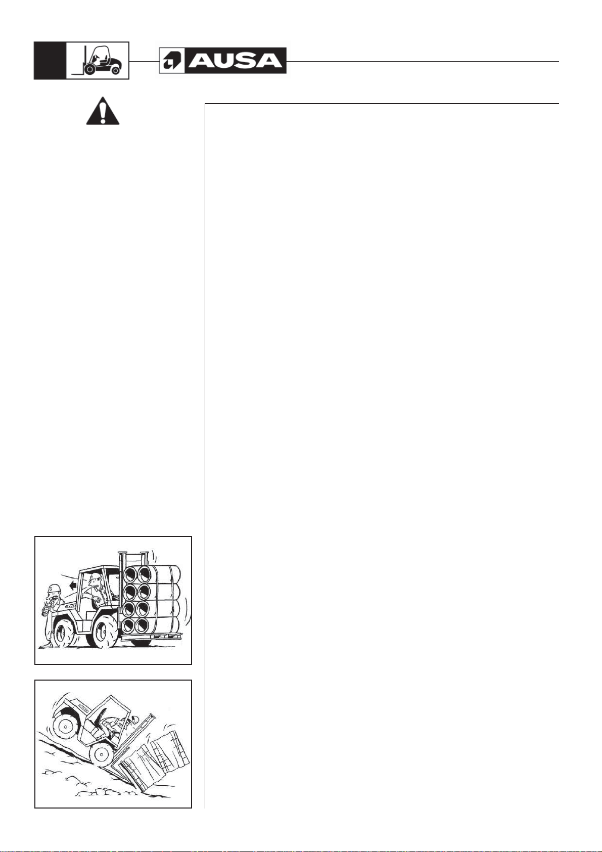
84
C300H / C300HI / C300H x4 / C300HI x4
C350H / C350HI / C350H x4 / C350HI x4
Special
Safety Messages
Driving in reverse
Ensure good visibility of the path to be taken. If the load being carried obstructs visibility,
drive in reverse with the utmost of caution.
Before reversing, the operator should ensure that this does not involve risks for the
forklift, people or objects in the surrounding area (fig. 1).
Driving on gradients
Special care should be taken when driving on gradients: move slowly, avoid placing
the machine across the gradient and do not work on higher gradients than those
recommended.
The maximum permitted gradient does not imply that it is possible to manoeuvre here in
absolute safety under full load, ground and operating conditions.
Gradients should be descended in reverse, with the load facing the direction of greatest
stability (fig. 2).
Rudiments of static equilibrium
In order that the forklift is able to handle loads in a stable and safe manner, certain
equilibrium conditions must exist and be maintained between the load and the machinery.
Therefore, the forklift is fitted with counterweights at the rear. These are designed to
compensate for the weight of the load being carried, as long as the centre of gravity
of the load and the forklift are within certain established limits. In order to calculate the
values of the transportable weight and the position of the centre of gravity permitted for
the forklift see the Load Charts in the section OPERATING THE MACHINE on this
Operator’s and Safety Manual .
Rudiments of dynamic equilibrium
While the forklift is moving, and as it gains speed, the equilibrium conditions of the
load-forklift unit are modified as the centre of gravity shifts. This is accentuated on lifting
loads, turning, braking, etc. In these conditions it is necessary to take the utmost care
to ensure that the centre of gravity of the load is maintained within the specifications
showed on the load chart plate.
Static equilibrium of a conventional forklift
The forklift counterweight produces a situation of imbalance when the forklift is unloaded.
The centre of gravity is maintained low and close to the rear of the forklift. When the load
is collected, the imbalance is corrected and the centre of gravity shifts forward. If the
load is within the margins given on the load chart, equilibrium is maintained. As the
load is lifted, the centre of gravity also rises, shifting upwards. At the moment that the
centre of gravity shifts beyond the forklift, the equilibrium is lost and the forklift becomes
unstable. Therefore, the forklift should not move while the load is raised.
Stability
Do not carry unstable or loose loads, or loads which are oversized with respect to the
forklift. If very large or wide loads must be carried, every precaution must be taken to
prevent bumps or other possible accidents.
When carrying out lifting manoeuvres, particularly at height, ensure that the forklift is on
stable ground as levelled as possible.
Do not drive over objects which may endanger the stability of the machine.
(fig. 1)
(fig. 2)

C300H / C300HI / C300H x4 / C300HI x4
C350H / C350HI / C350H x4 / C350HI x4
85
Special
Safety Messages
The triangle of horizontal stability
To prevent the loads which are being transported from falling, it is necessary to consider
the triangle of horizontal stability (fig. 1). This is an imaginary inverted triangle, with the
lower end located on the centre of the rear axle and the two upper vertices on each of the
front wheels. Stability is guaranteed when the centre of gravity of the combination load
(c)+ machine (m) remains within the limits of this imaginary triangle.
Longitudinal stabilization
The risk of longitudinal overturning increases if the forklift is driven while the load is
raised. Sharp braking and accelerating or rapid tilting movements decrease stability.
Transversal stability
The risk of overturning sideways increases on turning at incorrect speeds, while the forklift
is unloaded or when the load is raised. Rough ground, sharp braking or accelerating or
shifts in the load make these conditions worse.
Centre of gravity and the capacity of the forklift truck
Do not overload the forklift or handle loads which shift the centre of gravity beyond
that for which it is designed. Manoeuvre slowly, especially when changing direction on
slippery ground .
Do not handle loads that are unstable, loose or disproportionate to the size of the forks
and the forklift machine itself. Make certain that long or wide loads are fastened together
so as to be stable and secure.
The load and counterweight
The load should be lifted and lowered with the mast in vertical position or slightly
tilted backwards. The raised load should only be tilted forwards when it is about to be
unloaded.
Tilting the load forwards or backwards (swinging) is very useful for collecting or
positioning the load, but affects the longitudinal and lateral stability. Therefore, when
handling raised loads, do not swing the mast more than is absolutely essential.
The forklift may tip forwards when carrying a raised load with the mast tilted forwards, or
in the event of sudden braking or accelerating while the load is raised.
If using an accessory, attachment or tool, first check the permitted load. The combination
of the weight of the forklift plus the weight of the accessory or attachment reduces the
nominal load.
WARNING
This forklift is not designed to travel with elevated load or with the mast tilted forward.
Do not tilt forward the mast with the forks elevated except to pick up or deposit the
load.
The fully forward tilting mast angle is only intended to transport the forklift on a truck
bed, always without load.
For operating with load do not exceed 10º for the forward tilting mast angle.
(fig. 1)
WARNING

86
C300H / C300HI / C300H x4 / C300HI x4
C350H / C350HI / C350H x4 / C350HI x4
Special
Safety Messages
Load handling
• Know the lifting capacity of your forklift and operate within those limits.
See the Load Limit Charts shown in the section TECHNICAL SPECIFICATIONS
on this Operator’s Safety Manual and shown in a plate on the left mudguard.
• Never transport loads with the forks raised -keep them as low as possible to attain
maximum stability-. The risk of overturning increases when the forklift is driven with
the load raised. Keep it low when in transit. (fig. 1, 2)
• Do not drive on surfaces that could affect the stability of the machine.
• Only raise the forks when the machine is on a level, flat surface.
• If necessary to temporarily operate the forklift in rough, unimproved areas, be very
careful when operating near an open trench, a high bank or an overhang that can
fall and cause a roll over with the potential of serious injury or death. You must make
a careful judgement whether you and your forklift can be safely operated near any
of these areas.
• Stay off steep inclines and slopes. Hillside operation can be very dangerous due to
the constant potential of rollovers.
• When operating on modest inclines or slopes:
- Move very carefully and slowly.
- Keep the forks and load low.
- Keep the forks facing uphill at all times. This means driving in backwards down a
slope to maintain maximum load stability.
- Always travels directly up or down the slope.
- Do not travel across an incline.
- Never position the forklift sideways on a slope.
• Forks should only be raised on level stable ground. You must be the judge whether
ground conditions will permit the safe operation of the forklift. Operation on an
incline can be very dangerous.
Rain, snow, loose gravel or soft ground can be factors which may prevent the use
of the forklift.
• Keep the forks and the loads away from overhead obstructions.
• Never operate the forklift near or close to overhead power lines.
• If the forklift is operated in an enclosed area, use ventilation systems to replace the
exhaust fumes with fresh air.
• Use ventilation systems to remove any flammable dust or steam in the working
area.
• Do not overload the forklift and do not allow the load centre to move. Always
manoeuvre slowly and smoothly especially when changing direction.
• Keep the forks facing uphill at all times. This means reversing backwards down a
slope to maintain maximum load stability.
• When depositing a load to a height, tilt the mast forward just enough to leave the
load on a shelf or pile. When taking a load from a shelf, tilt the mast back just
enough to stabilise the load on the forks.
• Always operate the fork tilt lever slowly and smoothly. (fig. 2).
• Always drive with the forks in the low position and with the mast tilted slightly back.
• Make certain that long or wide loads are fastened together so as to be stable and
secure.
(fig. 1)
(fig. 2)

C300H / C300HI / C300H x4 / C300HI x4
C350H / C350HI / C350H x4 / C350HI x4
87
Special
Safety Messages
Critical speed
The speed at which the forklift moves affects its stability. When turning, braking, or
accelerating, the centre of gravity shifts within the triangle of stability. Sharp turns,
sudden braking or accelerating cause the centre of gravity to shift sharply and it may fall
outside the triangle. This is the moment when the stability of the forklift and the load are
not guaranteed and there is a risk of accident.
When manoeuvring reduce the speed of the forklift and avoid turning the steering wheel
sharply.
Do not drive the forklift at a fast speed and then attempt a turn as the forklift may tip over.
Always drive slowly when making a turn and keep the forks low when turning (fig. 1).
Accesses and doors
Make sure that the passages and doors along the route are sufficiently high to allow all
the forklift to pass.
When carrying out lifting manoeuvres, pay special attention to the height of the roof,
lighting and other overhead installations.
Ground surface
Check that the ground is strong enough to bear the forklift when loaded, especially when
approaching bridges, the edges of embankments, concrete floors elevators, etc. (fig. 2).
Lighting
The forklift working area should be adequately lit to prevent the risk of accident, running
over persons or colliding with obstacles. As soon as the daylight fades, the forklift lighting
system should be switched on. If the forklift is not equipped with lighting, make sure that
the working area is adequately lit. If this is not possible, do not continue working with the
forklift, this may result in an accident.
Loading bay. Communication. Shelving and installations. The load
The loading bay or area where the loads are handled should be correctly equipped
and signposted. The operating area of the forklift should be free of obstacles and
pedestrians, however if their presence is necessary, the pedestrians should move in
areas which have been duly marked as such and they should be easily distinguished,
for example, by wearing reflective jackets.
If the area is closed it should be well-ventilated and the forklift must be equipped
with lighting and exhaust gas purifier systems. The forklift operator should be able to
communicate normally with pedestrians. If the surrounding area is excessively noisy,
pedestrians should refrain from walking in the immediate vicinity. If this is unavoidable,
the utmost care should be taken. Radio communication equipment should not be
handled while driving the forklift. If it is necessary to use the radio, pull over to one side
and signal the position of the forklift, using the lights or hazard warning lights.
Shelving for the loads have a series of marked passageways. The width of these should
be at least the width of the forklift plus 40 in (1 m). If the passageway is two-way, the
width must be sufficient to allow two forklifts to pass plus an additional 55 in (1,5 m).
Before using the forklift to handle loads check the load and ensure that the weight does
not exceed the forklift capacity. At the same time, check that the load is stabilized and
correctly secured, to ensure that no part of the load falls off during transportation.
(fig. 1)
(fig. 2)
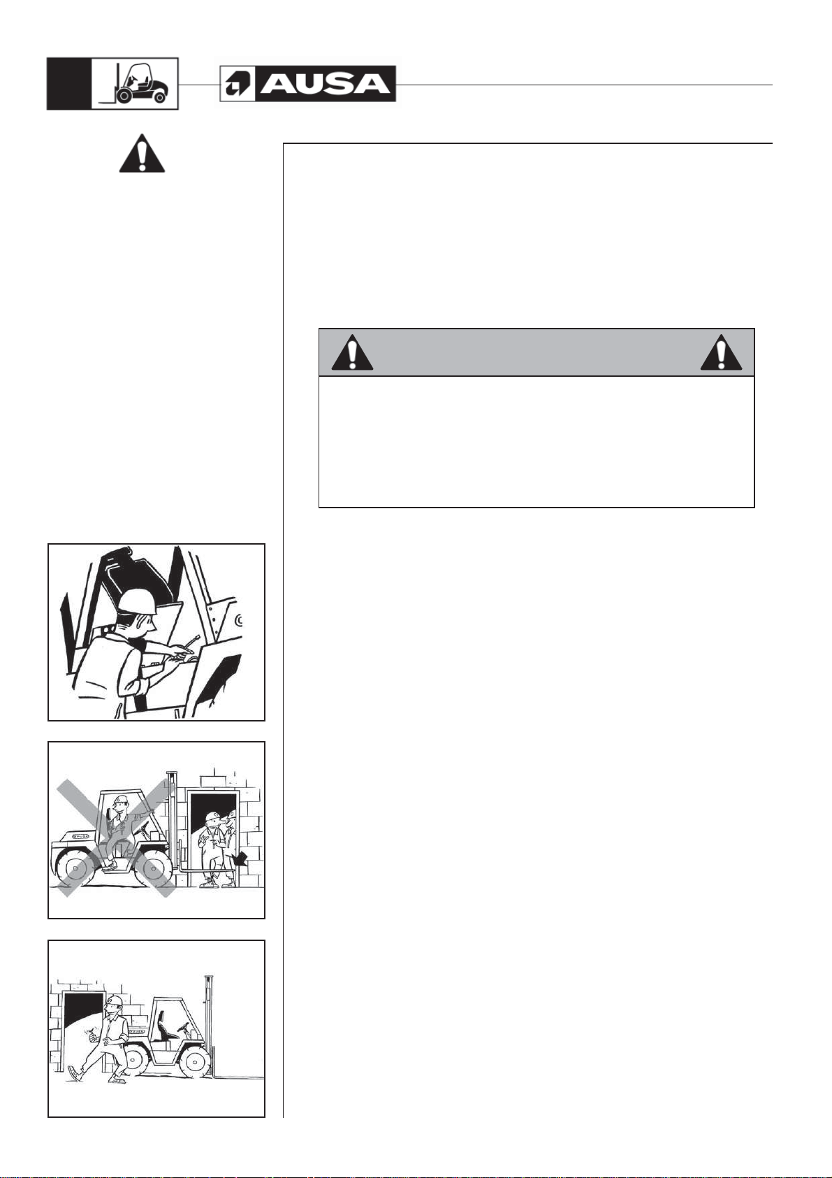
88
C300H / C300HI / C300H x4 / C300HI x4
C350H / C350HI / C350H x4 / C350HI x4
Special
Safety Messages
Order and cleanliness
Carrying out a series of checks before starting the forklift and keeping the operator cab
clean help to make the work safer.
To do so, follow the MAINTENANCE CHART given in this Operator’s and Safety
Manual strictly, and keep the operator cab clean and free of earth, gravel, mud, oil or
other objects which may cause falls.
Do not carry objects in the operator cab. These may injure the operator or accidentally
activate the forklift controls.
Overhead Guard
WARNING
You are protected by an overhead guard which complies with the provisions of
ISO 3449 and ISO 3471 / ASME B56.6. It protects the operator against falling
objects and, together with the mast, gives protection to the operator in the
event of an accidental tip over. The seat belt is an important part of this safety
system and must always be fastened before operating the forklift.
Failure to wear the seat belt in the event of an accidental tip over could result
serious injury or death as you could be crushed by the machine or by the
overhead guard.
The above decal is located on the side of the machine. Overhead Guard must be weekly
inspected for excessive damage cracks permanent deformation or signs of potential
cracks. If these incidents appear, structure must not be repaired but replaced for a new
one.
When leaving / parking the forklift (fig. 1, 2, 3)
A poorly parked forklift truck is a risk.
Park the forklift in the areas provided for this purpose, without obstructing the passage
of others, exits or entrances to stairs and emergency equipment.
• Place the forks or attachment in the fully lowered position.
• Set all the controls in the “0” neutral position.
• Apply the parking brake.
(fig. 1)
• Do not park the forklift on a slope. If it is necessary to park the forklift on a gradient,
in addition to using the parking brake, place chocks against the wheels.
• Stop the engine and cut the ignition circuit. Remove the ignition key.
• Lock all mechanisms to prevent any unauthorised person from using the machine.
• Remember that you are the key to safety. Good safety practices not only protect you
but also the people around you.
(fig. 2)
(fig. 3)

C300H / C300HI / C300H x4 / C300HI x4
C350H / C350HI / C350H x4 / C350HI x4
89
Parking the machine
Parking the machine and stopping the engine
Make certain that the forklift is parked on level ground when leaving it overnight. Also
park it on level ground before any scheduled maintenance is attempted.
- Lower the forks to the ground, lock the park brake and push directional switch to
NEUTRAL.
- Apply the parking brake
- If it is necessary to park the forklift on a gradient, in addition to using the park
brake, place chocks against the wheels.
- If the engine has been working at full load, run the engine at idle for 1 minute - as
this procedure will cool the engine components evenly.
- To stop the engine, turn the ignition switch key in a counter-clockwise motion.
- Remove the key from the ignition switch and take it with you. Never leave the key
in a parked machine.
- Lock all mechanisms to prevent any unauthorised person from using the forklift
- Remember that you are the key to safety. Good safety practices not only protect
you but also the people around you.
Be careful with the environment
At the end of the operating life of the machine, bring it to a recycling center or an scrapdealer.
It is absolutely forbidden to leave the materials in public places.
When changing the engine oil or other fluids, use a big collecting trough. Make sure
not to pollute the environment with emerging oil and other waste products (coolant,
batteries, etc.) bring them to the corresponding recycling centre.
In case that substances escape from the machine that are harmful to the environment
and/or to the people, take remedial measures inmediately, (eg.: if hydraulic oil emerges;
apply oil bonding agent, put a collecting vessel underneath, tighten leakage, remove
and dispose of contaminated earth, if required).
At the end of the life cycle of the machine, bring it to the specialised and recognised
recycling centres.

90
C300H / C300HI / C300H x4 / C300HI x4
C350H / C350HI / C350H x4 / C350HI x4
Transporting
the machine
Fastening the forklift to a lorry or trailer bed. (fig. 1, 2)
When transporting the forklift on a trailer or truck bed, carefully follow the instructions in
the Caution Decal. Move slowly and carefully up (or down) the loading ramps. Once on
the trailer make certain the forks are lowered, handbrake applied and the forks and tires
are blocked. Lastly make certain the forklift is securely tied down.
After the machine has been positioned on the Lorry/Trailer bed, put chocks at the front
and rear of the forklift tires.
Firmly fast the forklift to the trailer or truck bed with chains, cable or tie-down straps to
prevent any movement in the position shown in the picture 1.
Use the four eyes welded on to the chassis of the forklift purpose (fig. 2)
WARNING
Before you put the forklift on a trailer or truck bed, make certain that the ramp is
strong enough to support the load and that the parking surface is fee of debris,
oil, grease or ice.
• Do not transport the forklift with a full diesel fuel tank.
• Make certain your seat belt is properly fastened.
• Move the forklift slowly and carefully up the ramp onto the trailer.
• Shift the directional control lever to neutral.
• Apply the parking brake.
• In transit position lower the forks to their lowest level.
• Stop the engine and remove the key.
• Put blocks under the tips of each fork and tilt the mast slightly forward.
• Choks must be placed on all four wheels.
• Fast the forklift to the lorry chassis using chains, straps or sling cables
of sufficiente strengh.
Loading onto a trailer by crane (fig. 3)
lf a sling and crane are used to load the forklift onto a trailer or truck, attach the sling as
shown in the next figure.
Before lifting check that the sling cable is firmly attached. While lifting the forklift do not
permit riders on the forklift or by standers within 15ft (5m).
To lift the machine with a crane, bear in mind the following advice:
- Front slings must not be shorter than 8ft (2,5 meters).
- Always raise the machine in a balanced position.
- Keep the angle of inclination of the front sling approximately the same as the
angle of inclination of the mast.
(fig. 3) (fig. 1)(fig. 2)

C300H / C300HI / C300H x4 / C300HI x4
C350H / C350HI / C350H x4 / C350HI x4
91
Transporting
the machine
Towing the machine
If the machine must be towed for short distances, only do so with a solid tow-bar to
prevent any lateral sway. Attach the tow bar to the bolt at the rear of the counter weight
(fig. 1). Drive slowly and carefully at a speed not exceeding 6 mph (10 Km/h) and of
maximum for a duration not exceeding 3 minutes.. Comply with all state laws governing
the operation / towing of an off-highway machine on public roads and highways.
Before towing the machine:
Release the parking brake (fig. 2, 3, 4, 5)
In the event that the parking brake is blocked, due, for example, to a loss of brake fluid,
or because the engine does not start, proceed as follows to release it.
- Remove the bleeder (a) from the brake.
- Screw on the nipple (b)supplied in the forklift tool box.
- Remove handbrake release pressure hose and plug in the fitting with a M12 x 1,5
mm. thread plug (c).
- Using a hand pump lubricator (d) insert grease until the internal pressure
manages to release the parking brake.
- To finally release the parking brake, unscrew the nipple (b). The grease will come
out of the brake thanks to the operation of the internal springs.
- Re-assemble the bleeder (a).
- Disassemble plug (c) and connect handbrake hose again.
(fig. 1)
WARNING
a
Any repair to the brake system should be carried out by an authorized AUSA
dealer.
CAUTION
Not plugging in handbrake hose fitting before inserting grease into the brake
unit can lead to a hydrostatic pump damage. Contact your nearest AUSA
dealer if you have any doubt.
b
(fig. 3) (fig. 2)(fig. 4)
c
d
(fig. 5)

92
C300H / C300HI / C300H x4 / C300HI x4
C350H / C350HI / C350H x4 / C350HI x4
Transporting
the machine
By-passing the hydrostatic pump (fig. 1)
The forklift towing is only recommended when there is no other option during a breakdown so the hydrostatic transmission can be seriously damaged. Whenever is possible
it is recommended fixing in the place where is stopped. Otherwise, towing should only
occur over short distances and at low speed. Comply with all state laws governing the
operation / towing of an off-highway machine on public roads and highways.
CAUTION
It is possible to damage the drive motor by operating in bypass mode without
charge pressure. Move the forklift at a speed not more than 20% of maximum
for a duration not exceeding 3 minutes.
Use this procedure to bypass the pump to allow moving the forklift short distances when
you cannot start the engine.
To open the by-pass valves, screw-in (but not over-tight them) the centre screws of he
hydrostatic pump safety relief valves. To do so, loose the counter-nuts.
Once the machine is fixed, screw-out again the hydrostatic pump safety relief valves
tight the counter-nuts again.
(fig. 1)

C300H / C300HI / C300H x4 / C300HI x4
C350H / C350HI / C350H x4 / C350HI x4
93
Recommended
fluids and lubricants
This section specifies the recommended liquid and lubricants. See the
MAINTENANCE CHART on this Manual for the recommended change / service
intervals.
FLUID OR
LUBRICANT
FUEL
KUBOTA
V2403-M
ENGINE OIL
KUBOTA V3600T
ENGINE OIL
KUBOTA
V2403-M
ENGINE
COOLANT
KUBOTA V3600T
ENGINE
COOLANT
HYDRAULIC
CIRCUIT
C300H
FRONT AXLE
DIFFERENTIAL
C300H
FINAL DRIVE
ON THE FRONT
AXLE
C350H
FRONT AXLE
DIFFERENTIAL
C350H
FINAL DRIVE
ON THE FRONT
AXLE
REAR AXLE
DIFFERENTIAL
x4
FINAL DRIVE
ON THE REAR
AXLE x4
TRANSFER BOX
x2
TRANSFER BOX
x4
(FullGrip)
BRAKE FLUID
AND INCHING
WINDSCREEN
WIPER WASHER
BATTERY
ELECTROLYTE
GREASING
POINTS
SPECIFICATION REMARKS AUSA P/N
Usar gasoil limpio tipo
automoción (clase A),
preferentemente conforme
a la Directiva 98/70/CEE
modificada por la directiva
2003/17 o a la Norma EN 590
equivalente a las mismas. En
España corresponde al RD
1728/1999. Para el mercado
USA, debe ser conforme
Engine oil in accordance with
MIL- 2104C / API CD or higher
Engine oil in accordance with
MIL- 2104C / API CD or higher
Ethylene glycol antifreeze
with corrosion inhibitors for
aluminum engines with internal
combustion. 40% glycol / 60%
distilled water in Standard
machine.
Ethylene glycol antifreeze
with corrosion inhibitors for
aluminum engines with internal
combustion. 40% glycol / 60%
distilled water in Standard
Hydraulic oil ISO Grade VG-46
in accordance with ISO 6743/4
accordance with API GL5 / MIL
L-2105D with additive, LIMITED
accordance with API GL5 / MIL
L-2105D with additive, LIMITED
accordance with API GL5 / MIL
L-2105D with additive, LIMITED
accordance with API GL5 / MIL
L-2105D with additive, LIMITED
Aceite para transmisiones SAE
Aceite para transmisiones SAE
accordance with API GL5 / MIL
accordance with API GL5 / MIL
machine.
HV DIN 51524 Part 3 - class
SAE 10W Hydraulic Oil or ATF
fluid in accordance with CAT
TO-4 / TO-2 o ALLISON C-4
HVLP
Transmission oil SAE 90 in
Transmission oil SAE 90 in
Transmission oil SAE 90 in
Transmission oil SAE 90 in
Transmission oil SAE 90 in
Transmission oil SAE 90 in
SLIP
SLIP
SLIP
SLIP
90 según API GL5 / MIL-L-
2105B
90 según API GL5 / MIL-L-
2105B
L- 2105B
L- 2105B
/ C-3.
Distilled Water
Calcic grease NLGI-3
consistency
See section
ENGINE OIL
in this section
See section
ENGINE OIL
in this section
See section
ENGINE
COOLANT
in this section
See section
ENGINE
COOLANT
in this section
See section
HYDRAULIC
CIRCUIT OIL
in this section
See section
OIL FOR FullGrip
AND FRONT AXLE
in this section
See section
OIL FOR FullGrip
AND FRONT AXLE
in this section
See section
OIL FOR FullGrip
AND FRONT AXLE
in this section
See section
OIL FOR FullGrip
AND FRONT AXLE
in this section
See section
OIL FOR FullGrip
AND FRONT AXLE
in this section
See section
BRAKE FLUID
AND INCHING
in this section
Freezing point
temperature: - 20ºC
See section
BATTERY
ELECTROLYTE
in this section
See section
LUBRICATION
POINTS
in this Operator’s
Manual
461.00099.01 8.4 2.2
461.00099.01 13.2 3.5
45.00075.01 10 2.6
45.00075.01 13 3.4
461.00099.06 85 22.4
461.00099.09 4 1.8
461.00099.09 0.4 0.1
461.00016.00 6 1.5
461.00004.01 0.7 0.18
461.00004.01 3.3 0.8
461.00004.01 0.3 0.08
461.00004.01 3.25 0.9
461.00016.00 2.75 0.7
461.00015.00 1 0.26
465.00016.00 1.5 0.4
461.00009.00
CAPACITY
(Litres)
80 21.1
CAPACITY
(US Gal.)

94
C300H / C300HI / C300H x4 / C300HI x4
C350H / C350HI / C350H x4 / C350HI x4
Recommended
fluids and lubricants
Engine oil (fig. 1)
Use oil for 4-stroke engines in accordance with MIL-L-2104C / API CD or superior.
Always check the API quality on the oil container label to ensure that it is the required
quality.
Your machine leaves the factory with SAE 15W40 viscosity. However, depending on
the environment temperatures, refer to the following chart (fig. 1) to select the proper
viscosity.
If oils of different brand names are used, ensure that you completely empty the crankcase
before adding the new oil.
AUSA recommends oil REPSOL AUSA EFFICIENT for Diesel engines p/n 461.00099.01
Hydraulic Oil
- VG 32 for environment temperatures usually below 50ºF (10ºC)
- VG 46 for environment temperatures between 50F to 120ºF (10ºC to 40ºC)
- VG 68 for environment temperatures above 120ºF (40ºC)
AUSA recommends oil REPSOL AUSA EFFICIENT hydraulics p/n 461.00099.06
Coolant
Always use ethyiene-glycol antifreeze containing corrosion inhibitors especially for
internal combustion aluminium engines. The cooling systems must be filled with
distilled water and antifreeze solution (70 water, 30 antifreeze in a standard machine for
temperatures ranging from -17 °C to 127 °C) (50 water, 50 antifreeze for temperatures
ranging from -35 °C to 145 “C).
Oil for FullGrip® System and front axle
Oil AUSA COMPEN EFFICIENT p/n 461.00099.09 with the following characteristics:
- Friction coefficient modifying additives
- “Extreme pressure” and anti-wear capacity
- Good antirust and anticorrosion characteristics
- Excellent thermal stability
- Avoids vibrations and noises
Brake and inching fluid
Only use only SAE 10W or ATF oil in accordance with CAT TO-4 / TO-2 or
ALLISON C-4 / C-3.
AUSA recommends oil REPSOL AUSA EFFICIENT TRANSMISSIONS p/n 461.00099.07
CAUTION:
To avoid serious damage to the brake system or clutch system do not use fluids other
than the recommended one, or mix different fluids for topping up.
Battery electrolyte
This vehicle is equipped with a battery that requires maintenance.
(fig. 1)
Add distilled water if necessary.

C300H / C300HI / C300H x4 / C300HI x4
C350H / C350HI / C350H x4 / C350HI x4
Maintenance Chart
I: Inspect, verify, clean, lubricate, replace if necessary
C: Clean
95
EVERY
L: Lubricate
R: Replace
MOTOR
Oil and oil filter (1) R R R CUSTOMER
Alternator belt (1) I I R R DEALER
Valve clearance I DEALER
Compression of the cylinders I DEALER
FUEL SYSTEM
Air filter element (4) C R(5) R CUSTOMER
Intake air I R CUSTOMER
Fuel pipes and clamps I R(2) CUSTOMER
Fuel filter cartridge R CUSTOMER
Fuel prefilter (1) R R CUSTOMER
Fuel tank C CUSTOMER
Fuel injection nozzle injection pressure (2) I DEALER
Injection pump (timing) (2) I I DEALER
Fuel injection timer I DEALER
COOLING SYSTEM
Radiator hoses and clamp bands I R CUSTOMER
Cooling system pressure test I CUSTOMER
Water jacket (radiator interior) C DEALER
Coolant I R R CUSTOMER
ELECTRICAL SYSTEM
Battery electrolyte I I CUSTOMER
Battery connections I CUSTOMER
Dash panel indicators / Warning lights (3) I CUSTOMER
Battery I R CUSTOMER
Electric harness and loose connections I CUSTOMER
HYDRAULIC CIRCUIT
Oil and suction strainer (3) R R I CUSTOMER
Hydraulic cartridge R R CUSTOMER
Mast functions (3) I CUSTOMER
Pipes, hoses and fittings damages or leaks I CUSTOMER
Hoses I CUSTOMER
Steering (3) REPLACE EVERY 6 YEARS DEALER
Every 100 h.
Every 200 h.
Every 400 h.
Initial inspection (50 h)
Every 500 h.
Every 800 h.
Every 1000 h
Every 1500 h.
Every week
Every 3000 h.
Every year
Every month
Every 2 years
To be performed by
(1) Initial inspection. The initial maintenance is very important and must not be neglected.
(2) To be performed by an authorized AUSA dealer.
(3) Daily inspection item.
(4) More often under severe use such dusty areas, sand, snow, wet or muddy conditions.
(5) Or at least once a year.
(6) ….or six times after clean.

96
Maintenance Chart
I: Inspect, verify, clean, lubricate, replace if necessary
C: Clean
C300H / C300HI / C300H x4 / C300HI x4
C350H / C350HI / C350H x4 / C350HI x4
EVERY
L: Lubricate
R: Replace
GREASING POINTS
Masts guides L CUSTOMER
Nipples (see section "Greasing points" in this Manual) L CUSTOMER
Cables and articulations (throttle, lifting rams...) L CUSTOMER
TRANSFER-BOX
Oil (1) R R I R CUSTOMER
Oil leaks I CUSTOMER
Screws and nuts torque I CUSTOMER
AXLES (FRONT AND REAR)
Oil (1) R R I R CUSTOMER
Oil leaks I CUSTOMER
Fixation wheel nuts torque I CUSTOMER
Chassis fixation screws (torque) I DEALER
Cardan joint fixation screws (torque) I DEALER
Flange fixation nut (torque) I DEALER
Condition of tires and pressures I CUSTOMER
BRAKES
Brake fluid (3) R I R CUSTOMER
Foot brake adjustment (3) I I CUSTOMER
BODY / FRAME
Cabin I CUSTOMER
Seat belt (3) I CUSTOMER
Foot plate, access steps and handles (3) I/C CUSTOMER
Guards and covers (3) I CUSTOMER
Plates and decals (3) I/C CUSTOMER
Tipped cabin safety latch I CUSTOMER
Cabin lock I CUSTOMER
Every 100 h.
Every 200 h.
Every 400 h.
Initial inspection (50 h)
Every 500 h.
Every 800 h.
Every 1000 h
Every 1500 h.
Every week
Every 3000 h.
Every year
Every month
Every 2 years
To be performed by
(1) Initial inspection. The initial maintenance is very important and must not be neglected.
(2) To be performed by an authorized AUSA dealer.
(3) Daily inspection item.
(4) More often under severe use such dusty areas, sand, snow, wet or muddy conditions.
(5) Or at least once a year.
(6) ….or six times after clean.

C300H / C300HI / C300H x4 / C300HI x4
C350H / C350HI / C350H x4 / C350HI x4
97
Periodic
Maintenance
Operations
General comments
Only original AUSA spare parts should be used during maintenance
operations. This is the only way to guarantee that the AUSA machinery will
have the same operational level that it had upon delivery.
This forklift, as with any machine, contains parts and systems which are subject to wear
or require re-adjusting, and which may affect the reliability of the machine and the safety
of the operator, the environment and the surrounding area, such as for example, exhaust
gas emissions. The necessary maintenance should be carried out regularly in order to
ensure similar conditions to those existing on leaving the factory.
All repair and maintenance operations should be made while the forklift is unloaded,
the parking brake applied and the wheels blocked in order to keep the forklift stationary.
Disconnect the battery (fig. 1) before carrying out any work on the electrical system.
Never use a flame to check fluid levels.
Respect the environment
When changing oil or other fluids use a suitable container to collect the old fluid. Take
care not to cause damage to the environment and take all the replaced materials
(batteries, coolant, etc) to the appropriate recycling centres.
In the event of leaks of substances which may be harmful to persons or to the environment,
immediately take the necessary measures to reduce their impact, for example in the
case of oil leaks, plug the leak, use a recipient to collect the oil, sprinkle absorbent
material or collect up and remove the contaminated soil if necessary.
Access for maintenance
The engine, the transmission and filters are located under the cabin floor (fig.2). To
access them, you have to proceed as follows:
- Start the forklift and tilt the mast forwards (the operator remains seated in the
driver’s cabin).
- Stop the engine and remove the key from the ignition.
- Move the joystick to the right until reaching the maximum forward tilt.
- Stop the engine and remove the key from the ignition.
- Get down from the driver’s cabin.
- Pull the handle (a) located at the left side of the seat (fig. 3) to unlock the cabin
latch.
- The cabin will tip up, allowing access in order to carry out the maintenance
operations.
a
(fig. 3) (fig. 2) (fig. 1)

98
C300H / C300HI / C300H x4 / C300HI x4
C350H / C350HI / C350H x4 / C350HI x4
Periodic
Maintenance
Operations
b
- After lifting up the cabin, it should be secured using the safety lock
- CAB SAFETY PROP STOWED AWAY (fig. 1)
- CAB SAFETY PROP LOWERED INTO POSITION (fig. 2)
WARNING
Whenever the cabin is raised, the safety lock must be on. This prevents the
cabin from causing an accident on descending.
To access the upper part of the engine, after raising and securing the operator cabin, lift
the inspection cover (fig. 3)(a) by pulling on the lock (fig. 3)(b).
To access the sides of the engine, undo the bolt (fig. 4)(c) and nut (fig. 4)(d) and
remove the rear wheel cover. There is a wheel cover on each side of the machine.
Daily checks
- Before starting to work with the forklift, clean any oil or fuel spills, clean and
remove grease from hands and the soles of shoes and do not forget to make the
following checks:
- Condition of the lifting chains
(fig. 1)(fig. 2)
- Tyre pressure and condition of the tread.
- Brakes.
- Leaks in the hydraulic, coolant, fuel circuits, etc.
- Check the correct position and fastening of all the guards, caps and safety stops.
- Absence of cracks or other structural defects visible at first glance.
- Check that all the controls are operating correctly.
- Check fluid levels:
- fuel.
- brake fluid.
- hydraulic circuit fluid.
- coolant circuit fluid.
- Check that alarm and signalling devices are operating correctly (for example:
acoustic warning, air intake filter blocked warning, etc.)
- Check that informative and safety plates on the forklift are clean and in good
condition.
- Clean and check lighting and signalling system are operating correctly.
- Check electrical battery connections and level of electrolyte.
- Adjust the seat to your build.
- Carefully inspect the condition of the seatbelt, paying special attention to:
- Cuts or fraying on the belt.
- Wear or damage to the fastenings including the anchorage points.
- Poor functioning of the buckle or automatic reel device.
- Loose stitching.
Correct any problems before using the forklift.
a
d
c
Where necessary, refer the problem to an authorized AUSA dealer.
(fig. 3)
(fig. 4)
 Loading...