


Ausa C 200 H, C 200 HI, C 250 H, C 250 HI, C 250 HI LE OPERATOR’S MANUAL
...C 200 H
C 200 HI C 200 H x4 C 250 H C 250 HI
C 250 HI LE C 250 H x4
C 250 H x4 LE
OPERATOR’S MANUAL
ENGLISH
Original Manual
AUSA Forklift Truck
C 200 H
C 200 HI
C 200 H x4
C 250 H
C 250 HI
C 250 HI LE
C 250 H x4
C 250 HI x4 LE
Above chassis number 206 62866
ORIGINAL MANUAL
C200H-HI / C200H x4 / C250H-HI C250HI LE / C250H x4 / C250H x4 LE
Foreword
<![if ! IE]><![endif]>(fig. 1)
3
Thank you for choosing this AUSA forklift truck (hereinafter forklift). The purpose of this Operators and Safety Manual is to provide you, the user, with instructions concerning the productive, safe and efficient use of this forklift. You should read and understand this manual before operating the forklift. The Manual contains safety messages concerning the use of the forklift. Remember that “you” are the key to safety.
The preservation of these qualities over a long period of time is in your hands. The correct use of your forklift will allow you to make the most of the resultant benefits.
The Operator’s and Safety Manual also contains instructions for some adjustments and for maintenance of this fork-lift. Follow these instructions carefully while performing routine maintenance checks and keep a record of all maintenance. As wide variations in operating conditions may be experienced, you are urged to contact your AUSA Distributor to resolve any operational or service problems.
Please have all operators of this forklift read and understand this Operator’s and Safety Manual.
Any damage resulting from the incorrect use of the forklift shall not be considered to be the responsibility of AUSA. In the event of query, complaint or to place an order for spares, please contact your Official AUSA Dealer.
This forklift is designed and intended for off highway use. If it is temporarily operated on any public street or highway, the state and local laws governing speed, size, weight, brakes and lighting must be complied with.
For further information you may write, FAX or E-mail to:
AUSA Center, S.L.U.
Apartado P.O.B. 194
08243 MANRESA (Barcelona) SPAIN
Tel. 3493 874 75 52 / 93 874 73 11
Fax 3493 873 61 39 / 93 874 12 11 / 93 874 12 55 E-mail: ausa@ausa.com
Web: http://www.ausa.com
AUSA is continuously trying to improve the efficiency, productivity and safety of its products and reserves the right to make such improvements without incurring any obligation to make changes to forklifts previously sold. Because of this policy of striving for constant product improvement, the specifications and operating instructions shown in this Operator’s and Safety Manual may be different from prior forklift models. As such, we will not accept claims that are based on the data, illustrations or descriptions included in these instructions.
Only original AUSA spare parts should be used. This is the only way to guarantee that AUSA machinery has the same operational level as at the time of delivery. No alterations should be made to the forklift without the prior authorization of the manufacturer.
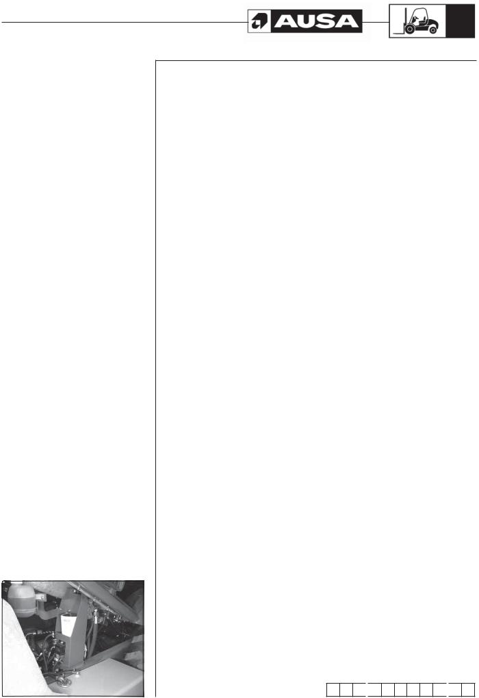
When not in use keep it stored on the forklift in the Manual holder box in the engine’s compartment in the control valve support (fig. 1).
M O P 
 1 0 0 9 1 0
 0 2
0 2

C200H-HI / C200H x4 / C250H-HI
4 |
C250HI LE / C250H x4 / C250H x4 LE |
|
Index |
|
|
|
Uses and improper Uses of the forklift ................................................................... |
5 |
|
Identification of the forklift components................................................................. |
6 |
|
Vehicle Identification and Serial Numbers .............................................................. |
7 |
|
Technical Specifications.......................................................................................... |
8 |
|
Decals / labels / identification plates all markets (except USA)............................ |
22 |
|
Decals / labels / identification plates (USA Market) ............................................... |
34 |
|
Controls and instruments........................................................................................ |
48 |
|
Instrument Panel and controls ................................................................................ |
51 |
|
Operating the forklift................................................................................................ |
57 |
|
Special procedures ................................................................................................. |
61 |
|
Special Safety Messages........................................................................................ |
64 |
|
Parking the machine ............................................................................................... |
72 |
|
Transporting the machine ....................................................................................... |
73 |
|
Recommended fluids and lubricants...................................................................... |
76 |
|
Maintenance Chart.................................................................................................. |
78 |
|
Periodic Maintenance Operations........................................................................... |
80 |
|
Hydrostatic transmission error conditions ............................................................. |
100 |
|
Electric circuit .......................................................................................................... |
102 |
|
Electric circuit |
|
|
C200H / C200HI / C200H x4 / C250HI LE / C250H x4 LE ................................ |
103 |
|
Electric wiring |
|
|
C200H / C200HI / C200H x4 / C250HI LE / C250H x4 LE ................................ |
107 |
|
Electric circuit |
|
|
C250H / C250HI / C250H x4 ............................................................................. |
108 |
|
Electric wiring |
|
|
C250H / C250HI / C250H x4 ............................................................................. |
113 |
|
Hydraulic diagram (Hydraulic appliances) ............................................................. |
114 |
|
Hydraulic diagram (Transmission) |
|
|
C200H / C200HI / C200H x4 / C250HI LE / C250H x4 LE ................................ |
115 |
|
Hydraulic diagram (Transmission) |
|
|
C250H / C250HI / C250H x4 ............................................................................. |
116 |
|
Transmission Troubleshooting ................................................................................ |
117 |
|
EC Certificate of Conformity.................................................................................... |
118 |

C200H-HI / C200H x4 / C250H-HI
C250HI LE / C250H x4 / C250H x4 LE |
5 |
||
|
|
|
|
Uses and improper |
|
Uses for which the forklift is designed |
|
|
|||
Uses of the forklift |
Forklifts C200H-HI / C250H x4 / C250H-HI / C250H x4 / C250HI LE / C250HI X4 LE have |
||
been designed and manufactured for lifting, handling and transporting loads on rough |
|||
|
ground and industrial use. The safety of individuals and of the loads carried must be |
||
|
ensured through the use of forks or other accessories and equipment. |
||
|
ROUGH TERRAIN USE (C200/250H) |
||
|
This forklift truck is designed for transporting and lifting loads on grounds not in good |
||
|
condition, roughly flat, not too steep slopes and small obstacles, so that the stability |
||
|
conditions are not optimal. |
||
|
INDUSTRIAL USE (C200/250HI) |
||
|
This forklift truck is designed for transporting and lifting loads on good condition floors, |
||
|
that means flat, levelled and paved ground, so that there are optimal stability conditions. |
||
|
Any use other than that described above shall be considered inappropriate and therefore |
||
|
improper. |
||
|
Strict adherence to the operating, maintenance and repair conditions specified by the |
||
|
manufacturer are essential in order to maintain the forklift in good working order. |
||
|
Driving, maintenance and repair of the forklift should only be carried out by suitably |
||
|
qualified personnel, with the necessary tools and knowledge of the control and safety |
||
|
procedures relative to the forklift. When handling loads or carrying out maintenance |
||
|
and/or repair work, the occupational health and safety regulations, together with those |
||
|
relative to accident prevention, should be observed. |
||
|
When driving with the forklift on public highways, special care should be taken to ensure |
||
|
compliance with the current legislation for this type of vehicle (Highway Code). |
||
|
AUSA does not assume responsibility for any damage resulting from modifications |
||
|
made to the forklift without express authorization. |
||
|
|
The texts following this symbol provide information on recycling and protecting the |
|
|
environment. |
||
|
|
Improper use |
|
|
Improper use is understood to mean the use of the forklift in a manner not in keeping |
||
|
with the criteria and instructions given in this Operator’s and Safety Manual and in a way |
||
|
which might cause damage to persons or objects. |
||
|
Some of the more common and dangerous examples of improper use are given below: |
||
|
|
- Carrying persons other than the operator on the forklift. |
|
|
|
- |
Not strictly observing the instructions for use and maintenance given in this |
|
|
|
Operator’s and Safety Manual. |
|
|
- |
Exceeding the limits for load and centre of gravity given in the relevant load |
|
|
|
charts. |
|
|
- Working on unstable, unshared grounds or at the edges of trenches and ditches. |
|
|
|
- Working on excessively steep slopes. |
|
|
|
- |
The use of accessories or equipment for purposes other than those for which |
|
|
|
they have been designed. |
|
|
- The use of accessories or equipment not manufactured or authorized by AUSA. |
|
|
|
|
|

6
Identification of the forklift components
8
11
7
C200H-HI / C200H x4 / C250H-HI
C250HI LE / C250H x4 / C250H x4 LE
Term such as right, left, front and rear when used in this Operator’s and Safety Manual indicate the right and left sides of the machine, the front and back of the machine, as viewed from the operators seat looking forward.
10 |
|
1 |
|
9 |
|
10 |
||
|
|
|
|
|
|
|
|
|
|
|
|
|
|
|
|
|
|
2
4
3
|
|
6 |
|
5 |
|
|
|
||
|
Identification components |
|
||
1- |
Overhead guard. |
|
||
2- |
Driving and load control (Joystick) |
|
||
3- |
Parking brake switch. |
|
||
4- |
Driver seat with seat belt. |
|
||
5- |
Diesel tank. |
|
||
6- |
Hydraulic tank. |
|
||
7- |
Forks. |
|
||
8- |
Lifting mast. |
|
||
9- |
Rotating beacon. |
|
||
10- |
Lighting equipment (). |
|
||
11- Rear-view mirror.

C200H-HI / C200H x4 / C250H-HI C250HI LE / C250H x4 / C250H x4 LE
Vehicle
Identification
and Serial
Numbers
<![if ! IE]><![endif]>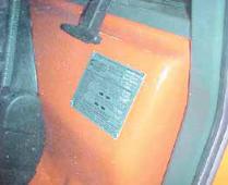 (fig. 1)
<![endif]>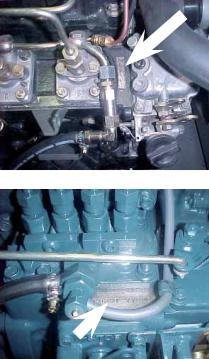 (fig. 4 – KUBOTA V2403-M) (fig. 3 - ISUZU 4LE2) (fig. 2)
7
¡Important! Write your machine Model number, date of sale, chassis and engine serial number in the spaces provided below. Give this information to your AUSA dealer when you need parts or information for your machine. Make a record of these numbers in your files.
Model number:.....................................................................
Date of sale: .........................................................................
Chassis serial number: ........................................................
Engine serial number: ..........................................................
The Vehicle Identification Plate is located at the left of the operators seat (fig. 1). The Engine Serial Number is located on the left side of the engine (fig. 3-4). The Chassis Serial Number is located on the right side of the chassis (fig. 2).
Principals components of identification plates
The plates of every components not built directly by AUSA, (for example: engines, pumps, etc.) are directly applied on the same components, in points where the respective makers put them originally.
8
Technical
Specifications
C200H-HI / C200H x4 / C250H-HI C250HI LE / C250H x4 / C250H x4 LE
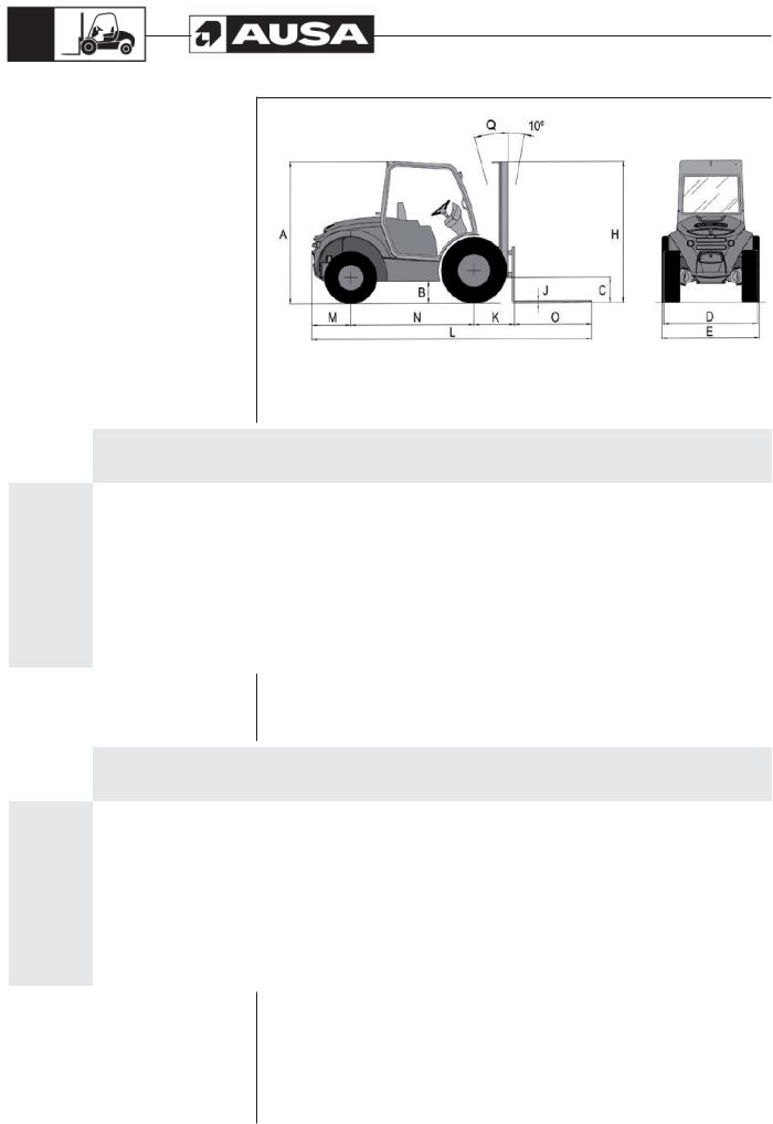
Dimensions (in)
|
|
|
|
|
|
|
|
|
|
|
|
|
|
|
|
|
|
|
|
|
|
|
|
E |
|
|
|
|
|
|
|
|
A |
B |
C |
|
|
D |
|
|
|
F |
G |
I |
J |
K |
L |
|
|
|
narrow |
|
wide |
||||||||||
|
|
|
|
|
|
|
|
|
|
|
|
|
|
||
|
|
|
|
|
|
|
version |
|
version |
|
|
|
|
|
|
|
|
|
|
|
|
|
|
|
|
|
|
|
|
|
|
C 200 H |
6ft 7.1in |
8.1in |
11.6in |
|
|
4ft 5.5in |
4ft 6.1in |
|
- |
R 9ft 2.2in |
8ft 6.4in |
4in |
1.6in |
2ft |
13ft 11in |
COMPACT |
|
|
|
||||||||||||
|
|
|
|
|
|
|
|
|
|
|
|
|
|
|
|
|
|
|
|
|
|
|
|
|
|
|
|
|
|
|
|
C 200 H |
|
|
|
|
|
|
|
|
|
|
|
|
|
|
|
C 200 HI |
6ft 8.7in |
9.6in |
12.2in |
|
|
4ft 6.1in |
4ft 9.5in |
|
5ft 10in |
R 9ft 2.2in |
8ft 6.4in |
4in |
1.6in |
2ft |
13ft 11in |
C 250 HI LE |
|
|
|
|
|
|
|
|
|
|
|
|
|
|
|
|
|
|
|
|
|
|
|
|
|
|
|
|
|
|
|
C 200 H x4 |
6ft 9.9in |
10.6in |
12.2in |
|
|
4ft 6.8in |
4ft 9.5in |
|
5ft 10in |
R 14ft 5.2in |
9ft 6.2in |
4in |
1.6in |
2ft |
13ft 11in |
C 250 H x4 LE |
|
|
|
||||||||||||
|
|
|
|
|
|
|
|
|
|
|
|
|
|
|
|
|
|
|
|
|
|
|
|
|
|
|
|
|
|
|
|
C 250 H |
7ft 0.6in |
11in |
15.3in |
|
|
4ft 6.1in |
4ft 11.5in |
|
5ft 11.2in |
R 9ft 2.2in |
8ft 6.4in |
5.1in |
1.8in |
2.01ft |
13ft 11.1in |
C 250 HI |
|
|
|
||||||||||||
|
|
|
|
|
|
|
|
|
|
|
|
|
|
|
|
|
|
|
|
|
|
|
|
|
|
|
|
|
|
|
|
C 250 H x4 |
6ft 11.5in |
12.6in |
15.3in |
|
|
4ft 6.8in |
4ft 11.5in |
|
5ft 11.2in |
R 14ft 5.2in |
9ft 6.2in |
5.1in |
1.8in |
2.01ft |
13ft 11.1in |
|
|
|
|
|
|
|
|
|
|
|
|
|
|
|
|
|
|
|
|
|
|
|
|
|
|
|
|
|
|
|
|
Dimensions (mm)
|
|
|
|
|
|
|
|
|
|
|
|
|
|
|
|
|
|
|
|
|
|
|
|
E |
|
|
|
|
|
|
|
|
A |
B |
C |
|
|
D |
|
|
|
F |
G |
I |
J |
K |
L |
|
|
|
narrow |
|
wide |
||||||||||
|
|
|
|
|
|
|
|
|
|
|
|
|
|
||
|
|
|
|
|
|
|
version |
|
version |
|
|
|
|
|
|
|
|
|
|
|
|
|
|
|
|
|
|
|
|
|
|
C 200 H |
2010 |
205 |
295 |
|
|
1360 |
1375 |
|
- |
R 2800 |
2600 |
100 |
40 |
610 |
4240 |
COMPACT |
|
|
|
||||||||||||
|
|
|
|
|
|
|
|
|
|
|
|
|
|
|
|
|
|
|
|
|
|
|
|
|
|
|
|
|
|
|
|
C 200 H |
|
|
|
|
|
|
|
|
|
|
|
|
|
|
|
C 200 HI |
2050 |
245 |
310 |
|
|
1375 |
1460 |
|
1782 |
R 2800 |
2600 |
100 |
40 |
610 |
4240 |
C 250 HI LE |
|
|
|
|
|
|
|
|
|
|
|
|
|
|
|
|
|
|
|
|
|
|
|
|
|
|
|
|
|
|
|
C 200 H x4 |
2080 |
270 |
310 |
|
|
1392 |
1460 |
|
1782 |
R 4400 |
2900 |
100 |
40 |
610 |
4240 |
C 250 H x4 LE |
|
|
|
||||||||||||
|
|
|
|
|
|
|
|
|
|
|
|
|
|
|
|
|
|
|
|
|
|
|
|
|
|
|
|
|
|
|
|
C 250 H |
2150 |
280 |
390 |
|
|
1375 |
1510 |
|
1810 |
R 2800 |
2600 |
130 |
45 |
615 |
4245 |
C 250 HI |
|
|
|
||||||||||||
|
|
|
|
|
|
|
|
|
|
|
|
|
|
|
|
|
|
|
|
|
|
|
|
|
|
|
|
|
|
|
|
C 250 H x4 |
2120 |
320 |
390 |
|
|
1392 |
1510 |
|
1810 |
R 4400 |
2900 |
130 |
45 |
615 |
4245 |
|
|
|
|
|
|
|
|
|
|
|
|
|
|
|
|
|
|
|
|
|
|
|
|
|
|
|
|
|
|
|
|
C200H-HI / C200H x4 / C250H-HI
C250HI LE / C250H x4 / C250H x4 LE |
9 |
||
|
|
|
|
|
|
Technical |
|
|
|
|
|
|
|
|
|
|
|
|
|
|
||||
|
Specifications |
|
|
Mast chart (in) |
|
|
|
|
|
|
|
|
|
|||||||
|
|
|
|
|
|
|
|
|
|
|
|
|
|
|
|
|
||||
|
|
|
|
|
|
|
|
|
|
|
|
|
|
|
|
|
|
|
|
|
|
|
|
|
|
|
|
|
|
|
|
|
|
|
|
|
|
|
|
|
|
|
|
|
|
Machine height |
with mast retracted |
Machine height with mast extended |
|
Pay Load (lb.) at maximum height. |
|
|
||||||||||
|
|
|
|
|
|
(ft in) |
|
|
(ft in) |
|
|
Load center at 24 in (600 mm) (USA) |
|
|
||||||
|
Max. |
|
Free |
|
|
|
|
|
|
|
|
|
|
|
|
|
|
|
|
|
|
|
|
C200H |
|
|
|
|
|
C200H |
|
|
|
|
|
|
|
|
|
||
Type of |
lifting |
|
|
|
|
|
|
|
|
C200H |
|
|
|
|
|
|
|
|||
Front axle |
lift |
|
|
|
|
|
|
|
|
|
|
|
|
|||||||
mast |
height |
C200H |
C200HI |
|
|
|
C250H |
C200H |
C200HI |
C250H |
C200H |
C200H |
C200HI |
C250H |
C250H |
C250HI |
|
|||
|
(ft in) |
|
COMPACT |
|
||||||||||||||||
|
(ft in) |
|
C200Hx4 |
C250HI |
C200Hx4 |
C250HI |
(narrow |
(wide |
(narrow |
(narrow |
(wide |
(narrow |
|
|||||||
|
|
|
COMPACT |
COMPACT |
(narrow |
|
||||||||||||||
|
|
|
|
|
C250HI LE |
C250Hx4 |
|
C250HI LE |
C250Hx4 |
axle) |
axle) |
axle) |
axle) |
axle) |
axle) |
axle) |
|
|||
|
|
|
|
|
C250Hx4 LE |
|
|
C250Hx4 LE |
|
|
|
|
|
|
|
|
||||
|
|
|
|
|
|
|
|
|
|
|
|
|
|
|
|
|||||
|
|
|
|
|
|
|
|
|
|
|
|
|
|
|
|
|
|
|
|
|
Duplex |
10ft 10in |
Narrow / |
4.7in |
- |
7ft 10.3in |
8ft 0.9in |
- |
13ft 7.4in |
13ft 10in |
- |
4040 |
4040 |
4040 |
5060 |
5060 |
5060 |
|
|||
(Std.) |
Wide (op.) |
|
||||||||||||||||||
|
|
|
|
|
|
|
|
|
|
|
|
|
|
|
|
|
|
|
||
|
|
|
|
|
|
|
|
|
|
|
|
|
|
|
|
|
|
|
|
|
Duplex |
8ft 6in |
Narrow / |
4.7in |
6ft 7.7in |
6ft 8.5in |
6ft 11in |
7ft 11.7in |
11ft 3.9in |
11ft 6.4in |
4040 |
4040 |
4040 |
4040 |
5060 |
5060 |
5060 |
|
|||
Wide (op.) |
|
|||||||||||||||||||
|
|
|
|
|
|
|
|
|
|
|
|
|
|
|
|
|
|
|
|
|
Duplex |
11ft 10in |
Narrow / |
4.7in |
- |
8ft 4.2in |
8ft 6.8in |
- |
14ft 7.2in |
14ft 9.8in |
- |
4040 |
4040 |
4040 |
4650 |
4850 |
5060 |
|
|||
Wide (op.) |
|
|||||||||||||||||||
|
|
|
|
|
|
|
|
|
|
|
|
|
|
|
|
|
|
|
|
|
Duplex |
14ft 9in |
Wide / |
4.7in |
- |
9ft 9.9in |
10ft 0.5in |
- |
17ft 6.6in |
17ft 9.2in |
- |
- |
3640 |
3640 |
- |
4250 |
5060 |
|
|||
Narrow (HI) |
|
|||||||||||||||||||
|
|
|
|
|
|
|
|
|
|
|
|
|
|
|
|
|
|
|
|
|
|
|
|
|
|
|
|
|
|
|
|
|
|
|
|
|
|
|
|
|
|
Triplex |
12ft 2in |
Narrow / |
4ft 4in |
6ft 7.7in |
6ft 8.5in |
8ft 11.5in |
15ft |
15ft 0.7in |
15ft 3.7in |
4040 |
3640 |
4040 |
4040 |
4450 |
4650 |
5060 |
|
|||
(free lift) |
Wide (op.) |
|
||||||||||||||||||
|
|
|
|
|
|
|
|
|
|
|
|
|
|
|
|
|
|
|
||
|
|
|
|
|
|
|
|
|
|
|
|
|
|
|
|
|
|
|
|
|
Triplex |
14ft 1in |
Wide / |
4ft 4in |
- |
7ft 4.5in |
7ft 7.5in |
- |
17ft 2in |
17ft 5in |
- |
- |
3640 |
3640 |
- |
4250 |
5060 |
|
|||
(free lift) |
Narrow (HI) |
|
||||||||||||||||||
|
|
|
|
|
|
|
|
|
|
|
|
|
|
|
|
|
|
|
||
|
|
|
|
|
|
|
|
|
|
|
|
|
|
|
|
|
|
|
|
|
Triplex |
17ft 8in |
Narrow / |
5ft 6in |
- |
8ft 6.8in |
8ft 9.7in |
- |
20ft 7.8in |
20ft 11in |
- |
- |
2220 |
3440 |
- |
2220 |
4430 |
|
|||
(free lift) |
Wide (op.) |
|
||||||||||||||||||
|
|
|
|
|
|
|
|
|
|
|
|
|
|
|
|
|
|
|
||
Mast chart (mm)
|
|
|
|
|
|
|
|
|
|
|
|
|
|
|
|
|
|
|
|
|
|
|
Machine height |
with mast retracted |
Machine height with mast extended |
|
Pay Load (Kg.) at maximum height |
|
|||||||||
|
|
|
|
|
|
(mm) |
|
|
(mm) |
|
|
|
||||||
|
|
|
|
|
|
|
|
|
|
|
|
|
|
|
|
|||
|
Max. |
|
Free |
|
|
|
|
|
|
|
|
|
|
|
|
|
|
|
|
|
|
C200H |
|
|
|
C200H |
|
|
|
|
|
|
|
|
|||
Type of |
lifting |
|
|
|
|
|
|
C200H |
|
|
|
|
|
|
||||
Front axle |
lift |
|
|
|
|
|
|
|
|
|
|
|
||||||
mast |
height |
C200H |
C200HI |
C250H |
C200H |
C200HI |
C250H |
C200H |
C200H |
C200HI |
C250H |
C250H |
C250HI |
|||||
|
(mm) |
COMPACT |
||||||||||||||||
|
(mm) |
|
C200Hx4 |
C250HI |
C200Hx4 |
C250HI |
(narrow |
(wide |
(narrow |
(narrow |
(wide |
(narrow |
||||||
|
|
|
COMPACT |
COMPACT |
(narrow |
|||||||||||||
|
|
|
|
|
C250HI LE |
C250Hx4 |
|
C250HI LE |
C250Hx4 |
axle) |
axle) |
axle) |
axle) |
axle) |
axle) |
axle) |
||
|
|
|
|
|
C250Hx4 LE |
|
|
C250Hx4 LE |
|
|
|
|
|
|
|
|||
|
|
|
|
|
|
|
|
|
|
|
|
|
|
|
||||
|
|
|
|
|
|
|
|
|
|
|
|
|
|
|
|
|
|
|
Duplex |
3300 |
Narrow / |
120 |
- |
2395 |
2460 |
- |
4150 |
4215 |
- |
2000 |
2000 |
2000 |
2500 |
2500 |
2500 |
||
(Std.) |
Wide (op.) |
|||||||||||||||||
|
|
|
|
|
|
|
|
|
|
|
|
|
|
|
|
|||
|
|
|
|
|
|
|
|
|
|
|
|
|
|
|
|
|
|
|
Duplex |
2600 |
Narrow / |
120 |
2025 |
2045 |
2110 |
2430 |
3450 |
3515 |
2000 |
2000 |
2000 |
2000 |
2500 |
2500 |
2500 |
||
Wide (op.) |
||||||||||||||||||
|
|
|
|
|
|
|
|
|
|
|
|
|
|
|
|
|
||
|
|
|
|
|
|
|
|
|
|
|
|
|
|
|
|
|
|
|
Duplex |
3600 |
Narrow / |
120 |
- |
2545 |
2610 |
- |
4450 |
4515 |
- |
2000 |
2000 |
2000 |
2300 |
2400 |
2500 |
||
Wide (op.) |
||||||||||||||||||
|
|
|
|
|
|
|
|
|
|
|
|
|
|
|
|
|
||
Duplex |
4500 |
Wide / |
120 |
- |
2995 |
3060 |
- |
5350 |
5415 |
- |
- |
1800 |
1800 |
- |
2100 |
2500 |
||
Narrow (HI) |
||||||||||||||||||
|
|
|
|
|
|
|
|
|
|
|
|
|
|
|
|
|
||
Triplex |
3700 |
Narrow / |
1130 |
2025 |
2045 |
2120 |
4570 |
4590 |
4665 |
2000 |
1800 |
2000 |
2000 |
2200 |
2300 |
2500 |
||
(free lift) |
Wide (op.) |
|||||||||||||||||
|
|
|
|
|
|
|
|
|
|
|
|
|
|
|
|
|||
|
|
|
|
|
|
|
|
|
|
|
|
|
|
|
|
|
|
|
Triplex |
4300 |
Wide / |
1330 |
- |
2245 |
2320 |
- |
5230 |
5300 |
- |
- |
1800 |
1800 |
- |
2100 |
2500 |
||
(free lift) |
Narrow (HI) |
|||||||||||||||||
|
|
|
|
|
|
|
|
|
|
|
|
|
|
|
|
|||
|
|
|
|
|
|
|
|
|
|
|
|
|
|
|
|
|
|
|
Triplex |
5400 |
Narrow / |
1680 |
- |
2610 |
2685 |
- |
6295 |
6370 |
- |
- |
1100 |
1700 |
- |
1100 |
2200 |
||
(free lift) |
Wide (op.) |
|||||||||||||||||
|
|
|
|
|
|
|
|
|
|
|
|
|
|
|
|
|||
|
|
|
|
|
|
|
|
|
|
|
|
|
|
|
|
|
|
|
10
Technical
Specifications
C200H-HI / C200H x4 / C250H-HI
C250HI LE / C250H x4 / C250H x4 LE
Diesel engine
Four cylinders, four strokes, water-cooled. Electric starter. Mixed radiator (water/oil).
C 200 H-HI / C 200 H x4 / C 250 HI LE / C 250 HI x4 LE: Isuzu 4LE2Tier II. Power 45.92 HP (33.8 kw at 2,700 rpm in accordance with SAE J 1349 Norm).
C 250 H-HI / C 250 H x4: KUBOTA V2403-M – E3B.
Power 49.6 HP (36.5 kw at 2,600 rpm in accordance with SAE J 1995 Norm).
See the engine instructions handbook.
Transmission
Hydrostatic system with variable flow pump and inching. Electronic control on C 250 H-HI / C 250 H x4 models.
C 200 H-HI / C 200 H x4 / C 250 HI LE / C 250 HI x4 LE: Hydrostatic motor with two speeds selected by electrical switch.
Maximum operating pressure: 4,713 PSI (325 bar).
C 250 H-HI / C 250 H x4: Hydrostatic motor with variable flow. Maximum operating pressure: 6,091 PSI (420 bar)
Both models with 2 wheel drive version (2WD) and 4 wheel drive version (4WD).
Permanent 4WD with COMPEN® System in Standard Machine 4x4 connectable on demand with “Full grip system®” ()
Directional control
The selection of the drive (forwards/ backwards) is made using a switch on the lower part of the joystick. A lamp in the shape of an arrow lights up on the top of it when a movement mode is selected.
Steering
Hydraulic powered with one double acting hydraulic cylinder on the rear axle.
Working pressure (all models): 2320 PSI (160 bar).
Wheels
Dimensions:
Dimensions
|
Front wheels |
Rear wheels |
||
|
|
|
|
|
C 200 H COMPACT |
10.0 / 75 - 15,3 (14 PR) |
6.50 |
- 10 |
(10 PR) |
|
|
|
|
|
C 200 H |
11.5 / 80 - 15,3 (14 PR) |
7.00 |
- 12 |
(12 PR) |
|
|
|
|
|
C 200 HI |
11.5 / 80 - 15,3 (14 PR) |
7.00 |
- 12 |
(12 PR) |
|
|
|
||
C 200 H x4 |
11.5 / 80 - 15,3 (14 PR) |
27 x 10 - 12 (14 PR) |
||
|
|
|
||
C 250 H |
12.5 / 80 - 18 (12 PR) |
7.00 - 12 (12 PR) |
||
|
|
|
||
C 250 HI |
12.5 / 80 - 18 (12 PR) |
7.00 - 12 (12 PR) |
||
|
|
|
||
C 250 H x4 |
12.5 / 80 - 18 (12 PR) |
10.0 / 75 - 15,3 (10 PR) |
||
|
|
|
|
|
C 250 HI LE |
12.5 / 80 - 18 (12 PR) |
7.00 - 12 |
(12 PR) |
|
|
|
|
||
C 250 H x4 LE |
12.5 / 80 - 18 (12 PR) |
10.0 / 75 - 15,3 (10 PR) |
||
|
|
|
|
|

C200H-HI / C200H x4 / C250H-HI
C250HI LE / C250H x4 / C250H x4 LE |
11 |
||
|
|
|
|
Technical
Specifications
Pressures:
Pressures
|
Front wheels |
Rear wheels |
|
|
|
C 200 H COMPACT |
96 psi (6.5 bar) |
65 psi (4.5 bar) |
|
|
|
C 200 H |
65 psi (4.5 bar) |
123 psi (8.5 bar) |
|
|
|
C 200 HI |
65 psi (4.5 bar) |
123 psi (8.5 bar) |
|
|
|
C 200 H x4 |
65 psi (4.5 bar) |
123 psi (8.5 bar) |
|
|
|
C 250 H |
65 psi (4.5 bar) |
123 psi (8.5 bar) |
|
|
|
C 250 HI |
65 psi (4.5 bar) |
123 psi (8.5 bar) |
|
|
|
C 250 H x4 |
65 psi (4.5 bar) |
51 psi (3.5 bar) |
|
|
|
C 250 HI LE |
65 psi (4.5 bar) |
123 psi (8.5 bar) |
|
|
|
C 250 H x4 LE |
65 psi (4.5 bar) |
123 psi (8.5 bar) |
|
|
|
Brakes
Service brake. Multidisc sealed hydraulic brake.
Parking brake. Multidisc sealed brake spring applied, hydraulically released.
Hydraulic circuit
One double gear pump driven by the hydrostatic pump of the transmission; one body for the mast operations and one for the hydraulic steering,.
Pump flows:
7.1 - 3.2 US gal/min (27 - 12 l/min) at 1500 rpm.
Monoblock control valve with two spools and selectable solenoid for side-shift. Restrictor valve to control the speed of the mast lowering with load.
Oil tank capacity: 12 US Gal (45 l.)
Service pressure:
C 200 H / C200HI / C 200 H x4: 2610 PSI (180 bar).
C 250 H / C250HI / C 250 H x4 / C 250 HI LE / C 250 HI x4 LE: 3190 PSI (220 bar).
Working temperature
From -15ºC to 40ºC.
Vibration and noise levels
Sound power level:
Warrantee sound power (according to 2000/14/EC sound emissions in the environment by machinery for outdoor use):
•C200H / HI – C200H x4 / C250HI LE / C250Hi LE x4: Lwa = 103 dB (A)
•C250H / HI – C250H x4: Lwa = 104 dB (A)
Sound pressure level on the operator’s site:
A weighted sound pressure in the operator’s ear measured (following norms EN 12053 and ISO 4871):
All models: Lpa = 85 dB (A)
Measurement uncertainty: 2,5 dB (A)
Vibration level produced by the machine:
Root-mean-square frequency-weighted, hand-arm vibration acceleration value: < 2,5 m/s2
Root-mean-square frequency-weighted, whole body vibration acceleration value: < 0,5 m/s2

12
Technical
Specifications
C200H-HI / C200H x4 / C250H-HI
C250HI LE / C250H x4 / C250H x4 LE
Electrical equipment
Electrical starter 2,0 Kw. Pre-heating spark plugs. Alternator of 35A (Isuzu Engine) and 480W (Kubota Engine). Battery 12V70 AH. Horn. Rotating beacon. Back-up alarm. Engine oil pressure alarm. Hydraulic oil level alarm. Coolant temperature alarm.
Weights |
|
|
|
|
Unladen weight (with full tanks): |
|
|
||
C 200 H-HI: 4200 kg |
(9,259 lbs). |
C 200 |
H x4: 4200 kg (9,259 lbs). |
|
C 250 H-HI: 4400 kg |
(9,700 lbs). |
C 250 |
H x4: 4400 kg (9,700 lbs) |
|
C 250 |
H x4 LE: 4400 kg (9,700 lbs). |
C 250 HI x4 LE: 4400 kg (9,700 lbs). |
||
(The Compact machine has the same weight than the C 200 H-HI). |
||||
Unladen weight (with full tanks): |
|
|
||
C 200 |
H-HI: 6200 kg |
(13,668 lbs). |
C 200 |
H x4: 6200 kg (13,668 lbs). |
C 250 |
H-HI: 6900 kg |
(15,211 lbs). |
C 250 |
H x4: 6900 kg (15,211 lbs) |
C 250 |
H x4 LE: 6900 kg (15,211 lbs). |
C 250 HI x4 LE: 6900 kg (15,211 lbs). |
||
(The Compact machine has the same weight than the C 200 H-HI).
Load Capacity
With the load center of the load at 500 mm. (see LOAD CHARTS In this manual)
C 200 H-HI / C 200 H x4: 2.000 Kg;
C 250 H-HI / C 250 H x4 / C 250 H x4 LE / C 250 HI x4 LE: 2.500 Kg. With the load center at 24 inches (600 mm) (see LOAD CHARTS In this manual)
C 200 H-HI / C 200 H x4: 4040 lbs (1835 Kg).
C 250 H-HI / C 250 H x4 / C 250 H x4 LE / C 250 HI x4 LE: 5060 lbs (2294 Kg).
Fork carriage
Class: FEM/ISO 2.
Standard mast
Side-shift 47 in. (1200 mm ) width Lifting height: 10ft. 10in. (3,30 m). Free litf: 6 inches (150 mm).
Forks length: 47 inches (1200 mm).
Lifting speed |
|
Without load: 103 ft/min (0,526 m./sec). |
with load: 101 ft/min (0,513 m./sec). |
Lowering speed |
|
Without load: 81 ft/min. (0,412 m./sec). |
With load: 125 ft/min (0,637 m./sec). |
WARNING
This forklift is not designed to travel with elevated load or with the mast tilted forward.
Do not tilt forward the mast with the forks elevated except to pick up or deposit the load.

C200H-HI / C200H x4 / C250H-HI
C250HI LE / C250H x4 / C250H x4 LE |
13 |
||
|
|
|
|
Technical |
Control panel |
|
|
Specifications |
The controls, switches and warning lights are integrated in the steering column and |
below the joystick. |
|
|
Lighting () |
|
Work lighting equipment, steering indicators, parking lights and warning. |
|
Overhead guard |
|
Manufactured according with ISO 3449 and ISO 3471 / ASME B56.6. |
WARNING
The operator is protected by an overhead guard which complies with the ISO 3449 and ISO 3471 / ASME B56.6 standards. It provides protection against falling objects and together with the mast, provides protection should the forklift overturn. The seat belt is an important part of the safety system and should always be fastened before starting to operate the forklift. In the event of the forklift overturning, if the seat belt is not fastened the operator may suffer serious injury or even loss of life as a result of crushing from the forklift or even the overhead guard itself.
Aisle widths
See graph.
C200H-HI / C200H x4 / C250H-HI
14 |
C250HI LE / C250H x4 / C250H x4 LE |
|
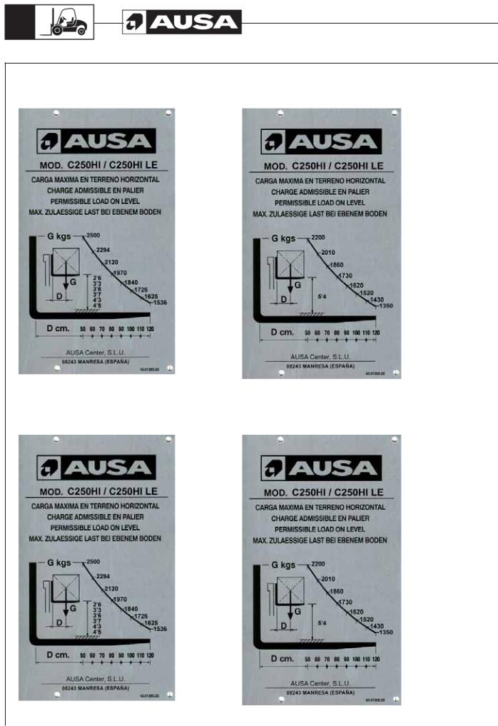
ROUGH TERRAIN USE (C200H / C250H)
This forklift truck is designed for transporting and lifting loads on grounds not in good condition, roughly flat, not too steep slopes and small obstacles, so that the stability conditions are not optimal.
Load charts for C200H / C200H x4 with wide axle (500 mm. load centre)
Load charts for C200H / C200H x4 with wide axle (24 in. load centre) |
|
|
|
|
|||||||
MODEL C200H / C200H x4 |
MODEL C200H / C200H x4 |
MODEL C200H / C200H x4 |
|||||||||
MAXIMUM FORKLIFT LOAD |
MAXIMUM FORKLIFT LOAD |
MAXIMUM FORKLIFT LOAD |
|||||||||
ON LEVEL SURFACE |
ON LEVEL SURFACE |
ON LEVEL SURFACE |
|||||||||
G LBS |
4040 |
|
|
G LBS |
|
3640 |
|
G LBS |
|
2220 |
|
|
3740 |
|
|
|
|
3360 |
|
|
|
2050 |
|
|
3470 |
|
|
|
3120 |
|
|
|
1910 |
|
|
G |
8ft 6in |
3240 |
|
G |
2920 |
|
G |
1780 |
|||
|
3040 |
|
14ft 1in |
2740 |
|
|
1670 |
||||
|
10ft 10in |
|
|
|
|
|
17ft 8in |
||||
D |
11ft 10in |
|
2861 |
D |
|
14ft 9in |
2570 |
D |
|
1565 |
|
|
|
|
|
||||||||
|
12ft 2in |
|
2700 |
|
|
|
2430 |
|
|
|
1490 |
|
|
|
|
|
|
|
|
|
|||
D inches |
24 28 32 36 |
40 |
44 48 |
D inches |
24 |
28 32 36 40 |
44 48 |
D inches |
24 |
28 32 36 40 |
44 48 |
D = Load center extension from face of forks |
D = Load center extension from face of forks |
D = Load center extension from face of forks |
|||||||||
AUSA Center, S.L.U. |
AUSA Center, S.L.U. |
AUSA Center, S.L.U. |
|||||||||
08243 MANRESA (SPAIN) |
|
08243 MANRESA (SPAIN) |
|
08243 MANRESA (SPAIN) |
|
||||||
|
|
|
43.01350.28 |
|
|
|
43.01350.28 |
|
|
|
43.01350.28 |

C200H-HI / C200H x4 / C250H-HI
C250HI LE / C250H x4 / C250H x4 LE |
15 |
||
|
|
|
|
Load charts for C200H / C200H x4 with narrow axle (500 mm. load centre)
Load charts for C200H / C200H x4 with narrow axle (24 in. load centre)
MODEL C200H / C200H x4 |
|||
MAXIMUM FORKLIFT LOAD |
|||
ON LEVEL SURFACE |
|
||
G LBS |
4040 |
|
|
|
3740 |
|
|
|
3470 |
|
|
G |
3240 |
|
|
8ft 6in |
3040 |
||
D |
10ft 10in |
||
11ft 10in |
|
2861 |
|
|
|
|
2700 |
D inches |
24 28 32 36 40 |
44 |
48 |
D = Load center extension from face of forks |
|||
AUSA Center, S.L.U. |
|
||
08243 MANRESA (SPAIN) |
|
|
|
|
|
43.01350.28 |
|
MODEL C200H / C200H x4 |
|||
MAXIMUM FORKLIFT LOAD |
|||
ON LEVEL SURFACE |
|||
G LBS |
|
3640 |
|
|
|
3362 |
|
|
|
3120 |
|
|
G |
2920 |
|
|
12ft 2in |
2740 |
|
D |
|
||
|
2570 |
||
|
|
||
|
|
|
2430 |
D inches |
24 |
28 32 36 40 |
44 48 |
D = Load center extension from face of forks |
|||
AUSA Center, S.L.U. |
|||
08243 MANRESA (SPAIN) |
|
||
|
|
|
43.01350.28 |
C200H-HI / C200H x4 / C250H-HI
16 |
C250HI LE / C250H x4 / C250H x4 LE |
|
Load charts for C250H / C250H x4 / C250H x4 LE with wide axle (500 mm. load centre)
Load charts for C250H / C250H x4 / C250H x4 LE with wide axle (24 in. load centre)
MODEL C250H / C250H x4 |
|||
MAXIMUM FORKLIFT LOAD |
|||
ON LEVEL SURFACE |
|||
G LBS |
|
5060 |
|
|
|
4670 |
|
|
|
4340 |
|
|
G |
4060 |
|
|
8ft 6in |
3800 |
|
|
|
||
D |
|
10ft 10in |
3580 |
|
|
|
3390 |
D inches |
24 |
28 32 36 40 |
44 48 |
D = Load center extension from face of forks |
|||
AUSA Center, S.L.U. |
|||
08243 MANRESA (SPAIN) |
|
||
|
|
|
43.01350.28 |
MODEL C250H / C250H x4 |
|||
MAXIMUM FORKLIFT LOAD |
|||
ON LEVEL SURFACE |
|||
G LBS |
|
4850 |
|
|
|
4400 |
|
|
|
4170 |
|
|
G |
3890 |
|
|
11ft 10in |
3650 |
|
D |
|
||
|
3440 |
||
|
|
||
|
|
|
3250 |
D inches |
24 |
28 32 36 40 |
44 48 |
D = Load center extension from face of forks |
|||
AUSA Center, S.L.U. |
|||
08243 MANRESA (SPAIN) |
|
||
|
|
|
43.01350.28 |
MODEL C250H / C250H x4 |
|||
MAXIMUM FORKLIFT LOAD |
|||
ON LEVEL SURFACE |
|||
G LBS |
|
4650 |
|
|
|
4300 |
|
|
|
3990 |
|
|
G |
3730 |
|
|
12ft 2in |
3500 |
|
D |
|
||
|
3300 |
||
|
|
||
|
|
|
3110 |
D inches |
24 |
28 32 36 40 |
44 48 |
D = Load center extension from face of forks |
|||
AUSA Center, S.L.U. |
|||
08243 MANRESA (SPAIN) |
|
||
|
|
|
43.01350.28 |
C200H-HI / C200H x4 / C250H-HI
C250HI LE / C250H x4 / C250H x4 LE |
17 |
||
|
|
|
|
Load charts for C250H / C250H x4 / C250H x4 LE with wide axle (500 mm. load centre)
Load charts for C250H / C250H x4 / C250H x4 LE with wide axle (24 in. load centre)
MODEL C250H / C250H x4 |
|||
MAXIMUM FORKLIFT LOAD |
|||
ON LEVEL SURFACE |
|||
G LBS |
|
4250 |
|
|
|
3930 |
|
|
|
3650 |
|
|
G |
3410 |
|
|
14ft 1in |
3200 |
|
|
|
||
D |
|
14ft 9in |
3000 |
|
|
||
|
|
|
2840 |
D inches |
24 |
28 32 36 40 |
44 48 |
D = Load center extension from face of forks |
|||
AUSA Center, S.L.U. |
|||
08243 MANRESA (SPAIN) |
|
||
|
|
|
43.01350.28 |
MODEL C250H / C250H x4 |
|||
MAXIMUM FORKLIFT LOAD |
|||
ON LEVEL SURFACE |
|||
G LBS |
|
2220 |
|
|
|
2050 |
|
|
|
1910 |
|
|
G |
1780 |
|
|
17ft 8in |
1670 |
|
D |
|
||
|
|
1575 |
|
|
|
|
1490 |
D inches |
24 |
28 32 36 40 |
44 48 |
D = Load center extension from face of forks |
|||
AUSA Center, S.L.U. |
|||
08243 MANRESA (SPAIN) |
|
||
|
|
|
43.01350.28 |

C200H-HI / C200H x4 / C250H-HI
18 |
C250HI LE / C250H x4 / C250H x4 LE |
|
Load charts for C250H / C250H x4 / C250H x4 LE with narrow axle (500 mm. load centre)
Load charts for C250H / C250H x4 / C250H x4 LE with narrow axle (24 in. load centre)
C200H-HI / C200H x4 / C250H-HI
C250HI LE / C250H x4 / C250H x4 LE |
19 |
||
|
|
|
|
INDUSTRIAL USE (C200H / C250HI)
This forklift truck is designed for transporting and lifting loads on good condition floors, that means flat, levelled and paved ground, so that there are optimal stability conditions.
Load charts for C200HI (500 mm. load centre)
Load charts for C200HI (24 in. load centre)
MODEL C200HI |
|
|
|
MAXIMUM FORKLIFT LOAD |
|||
ON LEVEL SURFACE |
|||
G LBS |
4040 |
|
|
|
3740 |
|
|
|
3470 |
|
|
G |
8ft 6in |
3240 |
|
|
3040 |
||
|
10ft 10in |
|
|
D |
11ft 10in |
|
2861 |
|
12ft 2in |
|
2700 |
|
|
|
|
D inches |
24 28 32 36 |
40 |
44 48 |
D = Load center extension from face of forks |
|||
AUSA Center, S.L.U. |
|||
08243 MANRESA (SPAIN) |
|
||
|
|
|
43.01350.28 |
MODEL C200HI |
|
||
MAXIMUM FORKLIFT LOAD |
|||
ON LEVEL SURFACE |
|||
G LBS |
|
3640 |
|
|
|
3350 |
|
|
|
3110 |
|
|
G |
2910 |
|
|
14ft 1in |
2735 |
|
|
|
||
D |
|
14ft 9in |
2580 |
|
|
||
|
|
|
2425 |
D inches |
24 |
28 32 36 40 |
44 48 |
D = Load center extension from face of forks |
|||
AUSA Center, S.L.U. |
|||
08243 MANRESA (SPAIN) |
|
||
|
|
|
43.01350.28 |
MODEL C200HI |
|
||
MAXIMUM FORKLIFT LOAD |
|||
ON LEVEL SURFACE |
|||
G LBS |
|
3440 |
|
|
|
3175 |
|
|
|
2955 |
|
|
G |
2755 |
|
|
17ft 8in |
2580 |
|
D |
|
||
|
|
2425 |
|
|
|
|
2290 |
D inches |
24 |
28 32 36 40 |
44 48 |
D = Load center extension from face of forks |
|||
AUSA Center, S.L.U. |
|||
08243 MANRESA (SPAIN) |
|
||
|
|
|
43.01350.28 |
C200H-HI / C200H x4 / C250H-HI
20 |
C250HI LE / C250H x4 / C250H x4 LE |
|
Load charts for C250HI / C250HI LE (500 mm. load centre)
Load charts for C250HI / C250HI LE (24 in. load centre)

C200H-HI / C200H x4 / C250H-HI
C250HI LE / C250H x4 / C250H x4 LE |
21 |
||
|
|
|
|
Technical |
Optional equipment |
|
|
||
Specifications |
Optional equipment is marked with an asterisk (). Optional equipment is only supplied |
|
at the express wish of the customer, for certain versions of forklift or even only in certain |
||
|
countries. |
|
|
- 4 WD transmission engaged by demand (FULL GRIP®) |
|
|
- Partially closed cab (front and rear windshield). |
|
|
- Closed cab with heating (standard for USA market). |
|
|
- Hydraulic shovels: 14 cu.ft (400 l.) and 21 cu.ft (600 l.) |
|
|
- 8ft 6in (2600 mm), 11ft 10in (3600 mm) and 14ft 9in (4500 mm) maximum height |
|
|
|
Duplex Mast |
|
- |
12ft2in (3700 mm), 14ft 1in (4300 mm) and 17ft 8in (5400 mm) maximum |
|
|
height Triplex mast (free lift) |
|
- 5ft 10in (1782 mm) and 5ft 11in (1810 mm) wide front axle (not available for the |
|
|
|
C200H Compact model). |
|
- 4ft 9in (1450 mm) 4ft 11in (1510 mm) narrow axle |
|
|
- 63 in. (1600 mm) and 47 in. (1200 mm) width load backrest (standard for USA |
|
|
|
market). |
|
- Electronic equipment anti-theft. |
|
|
- Oxi-catalytic exhaust purifier. |
|
|
- |
Exhaust Spark arrestor |
|
- Filter of gas-oil with water separator |
|
|
- Side-shift fork carriage 63 in. (1600 mm ) width |
|
|
- Super-elastic solid tyres. |
|
|
- |
Extra wide tyres. |
|
- |
Industrial use tyres |
|
- Lighting equipment (standard for USA market). |
|
|
- 4th hydraulic control for attachments |
|
|
Where the forklift comes equipped with accessories mounted at factory, please read the |
|
|
relevant Instruction Manual for each accessory carefully before use. Each accessory |
|
|
has its own Instruction Manual issued by the manufacturer, and this is provided with the |
|
|
forklift Operator’s and Safety Manual. |
|
|
Where accessories and equipment are fitted to the basic chassis or fork carriage plate at |
|
|
a later date by companies other than the manufacturer, the specifications and limitations |
|
|
of the forklift with respect to weight and dimensions, the adjustment and effectiveness |
|
|
of the lighting system, the protective system requirements, or any additional systems |
|
|
required to guarantee vehicle safety should be taken into consideration. |
|
|
|
|

C200H-HI / C200H x4 / C250H-HI
22 |
C250HI LE / C250H x4 / C250H x4 LE |
|
Decals / labels / identification plates all markets (except USA)
STICKER:
JOYSTICK FUNCTION
REFERENCE: |
DESCRIPTION: |
QUANTITY: |
|
10.15003.01 |
INDICATIVE STICKER 60X75 |
1 |
|
|
|
|
|
|
|
POSITION: |
|
|
|
Stuck on the inside of the right front fender, in the top center position. Just |
|
|
|
above sticker ref. 10.15005.01, at 0.1969 in. |
|
|
|
|
|
|
|
|
|
STICKER: |
|
|
|
JOYSTICK FUNCTION BUTTONS |
|
||
|
|
|
|
REFERENCE: |
DESCRIPTION: |
QUANTITY: |
|
10.15005.01 |
INDICATIVE STICKER MAST SIDE SHIFT |
1 |
|
|
|
|
|
|
|
POSITION: |
|
|
|
Stuck on the inside of the right front fender, in the top center position. Just |
|
|
|
above sticker ref. 10.15003.01, at 0.1969 in. |
|
|
|
|
|
|
|
|
|
STICKER: |
|
|
|
JOYSTICK FUNCTION BUTTONS |
|
||
|
|
|
|
REFERENCE: |
DESCRIPTION: |
QUANTITY: |
|
10.15009.00 |
INDICATIVE STICKER AUXILIAR HYDRAULIC LINE () |
1 |
|
|
|
|
|
|
|
POSITION: |
|
|
|
Stuck on the inside of the right front fender, in the top center position. Just |
|
|
|
above sticker ref. 10.15005.01, at 0.1969 in. |
|
|
|
|
|
C200H-HI / C200H x4 / C250H-HI
C250HI LE / C250H x4 / C250H x4 LE |
23 |
||
|
|
|
|
STICKER:
JOYSTICK FUNCTION BUTTONS
REFERENCE: |
DESCRIPTION: |
QUANTITY: |
|
10.15011.00 |
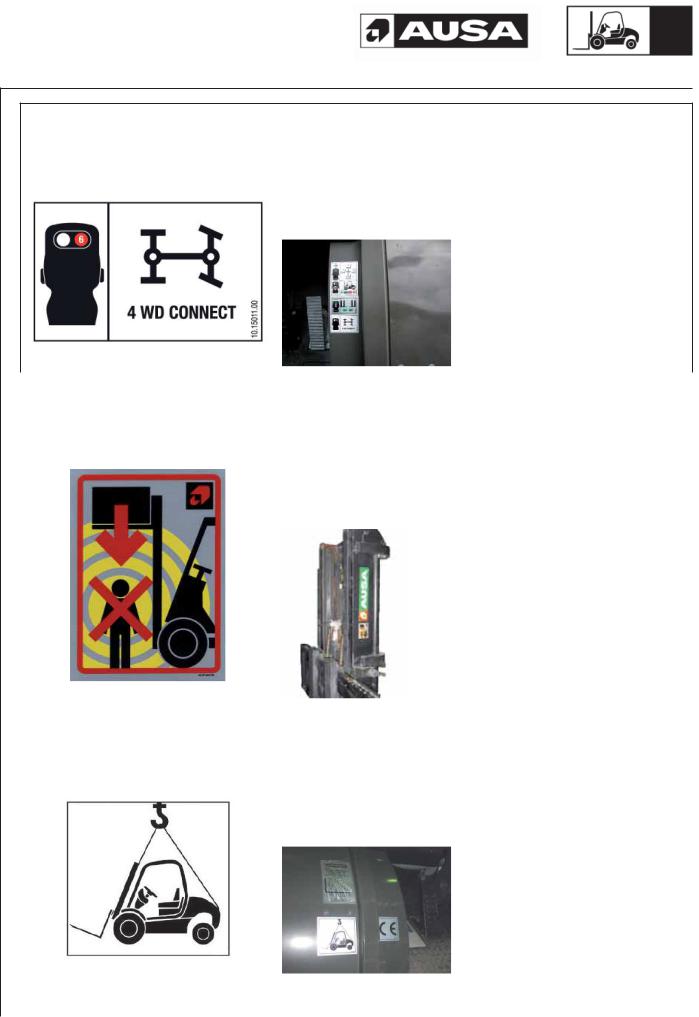
INDICATIVE STICKER 4WD CONNECTION () |
1 |
|
|
|
|
|
|
|
POSITION: |
|
|
|
Stuck on the inside of the right front fender, in the top center position. Just |
|
|
|
above sticker ref. 10.15005.01 o 10.15009.00, at 0.1969 in. |
|
|
|
|
|
|
|
|
|
STICKER: |
|
|
|
DANGEROUS AREA |
|
|
|
|
|
|
|
REFERENCE: |
DESCRIPTION: |
QUANTITY: |
|
45.01352.00 |
INDICATIVE STICKER |
2 |
|
|
|
|
|
|
|
POSITION: |
|
|
|
On both sides of the mast, above the beam, with its upper side aligned at 4ft 92 |
|
|
|
in from the ground, below the sticker ref. 13.12136.00 “AUSA Make”, and 0.3937 |
|
|
|
in away from it. |
|
|
|
|
|
|
|
|
|
STICKER: |
|
|
|
TO HOIST MACHINE |
|
|
|
|
|
|
|
REFERENCE: |
DESCRIPTION: |
QUANTITY: |
|
58.01353.01 |
INDICATIVE STICKER 105X100 |
1 |
|
|
|
|
|
|
|
POSITION: |
|
|
|
On the left side of the machine, at the lower exterior part of the front fender, |
|
|
|
aligned on its upper side with sticker 45.19101.00 “EC mark”. |
|
|
|
|
|

24 |
|
|
|
|
|
C200H-HI / C200H x4 / C250H-HI |
||
|
|
|
|
|
C250HI LE / C250H x4 / C250H x4 LE |
|||
|
|
|
|
|
|
|
||
|
|
|
|
|
|
|
|
|
|
|
|
|
|
|
|
|
|
|
STICKER: |
|
|
|
|
|
|
|
|
AUSA |
|
|
|
|
|
|
|
|
|
|
|
|
|
|
|
|
|
REFERENCE: |
|
|
DESCRIPTION: |
|
QUANTITY: |
||
|
13.12136.00 |
|
|
AUSA STICKER |
|
2 |
||
|
|
|
|
|
|
|
|
|
|
|
|
|
|
POSITION: |
|
|
|
|
|
|
|
|
On both sides of the machine, at a distance of 0.984 in and a height of 1.969 |
|||
|
|
|
|
|
in from the lower rear corner of each tank, aligned with the bottom of the tank. |
|||
|
|
|
|
|
|
|
|
|
|
|
|
|
|
|
|
|
|
|
STICKER: |
|
|
|
|
|
|
|
|
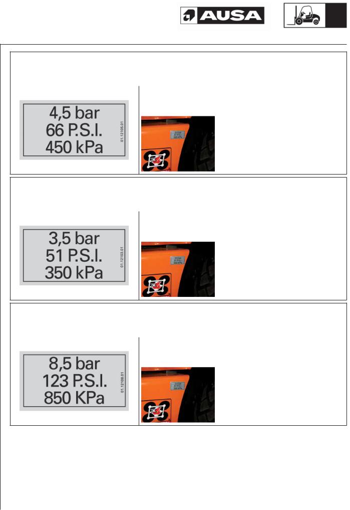
FRONT AXLE WHEELS INFLATED PRESSURE (Only on C200H compact) |
|
|
|||||
|
|
|
|
|
|
|
|
|
|
REFERENCE: |
|
|
DESCRIPTION: |
|
QUANTITY: |
||
|
01.12107.00 |
|
|
INDICATIVE STICKER 6,5 BAR / 96 PSI |
|
2 |
||
|
|
|
|
|
|
|
|
|
|
|
|
|
|
POSITION: |
|
|
|
|
|
|
|
|
On both sides of the machine, above the fenders of the front wheels, at the |
|||
|
|
|
|
|
front outer end of the fenders, aligned with the outer edge. |
|||
|
|
|
|
|
|
|
|
|
|
|
|
|
|
|
|
|
|
|
STICKER: |
|
|
|
|
|
|
|
|
FRONT AXLE WHEELS INFLATED PRESSURE (ALL MODELS EXCEPT C200H compact) |
|
|
|||||
|
|
|
|
|
|
|
|
|
|
REFERENCE: |
|
|
DESCRIPTION: |
|
QUANTITY: |
||
|
01.12105.01 |
|
|
INDICATIVE STICKER 4,5 BAR / 66 PSI |
|
2 |
||
|
|
|
|
|
|
|
|
|
|
|
|
|
|
POSITION: |
|
|
|
|
|
|
|
|
On both sides of the machine, above the fenders of the front wheels, at the |
|||
|
|
|
|
|
front outer end of the fenders, aligned with the outer edge. |
|||
|
|
|
|
|
|
|
|
|
|
|
|
|
|
|
|
|
|
C200H-HI / C200H x4 / C250H-HI
C250HI LE / C250H x4 / C250H x4 LE |
25 |
||
|
|
|
|
STICKER:
REAR AXLE WHEELS INFLATED PRESSURE (Only on C200H compact)
REFERENCE: |
DESCRIPTION: |
QUANTITY: |
01.12105.01 |
INDICATIVE STICKER 4.5 BAR / 66 PSI |
2 |
|
|
|
POSITION:
On both sides of the machine, on top of the vertical face, in the upper rear position of each tank, aligned with the bottom of the tank.
STICKER:
REAR AXLE WHEELS INFLATED PRESSURE (Only C250H x4)
REFERENCE: |
DESCRIPTION: |
QUANTITY: |
01.12103.01 |
INDICATIVE STICKER 3,5 BAR / 51 PSI |
2 |
|
|
|
POSITION:
On both sides of the machine, on top of the vertical face, in the upper rear position of each tank, aligned with the bottom of the tank.
STICKER:
REAR AXLE WHEELS INFLATED PRESSURE (All models except C200H compact and C250H x4)
REFERENCE: |
DESCRIPTION: |
QUANTITY: |
01.12108.01 |
INDICATIVE STICKER 8.5 BAR / 123 PSI |
2 |
|
|
|
POSITION:
On both sides of the machine, above the fenders of the front wheels, at the front outer end of the fenders, aligned with the outer edge.
26 |
|
|
|
|
|
C200H-HI / C200H x4 / C250H-HI |
||
|
|
|
|
|
C250HI LE / C250H x4 / C250H x4 LE |
|||
|
|
|
|
|
|
|
||
|
|
|
|
|
|
|
|
|
|
|
|
|
|
|
|
|
|
|
STICKER: |
|
|
|
|
|
|
|
|
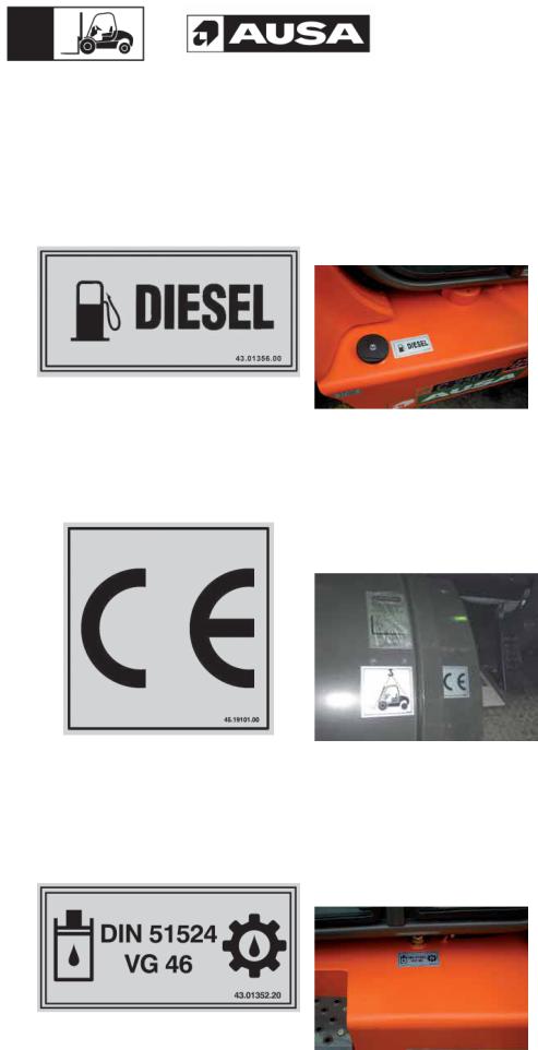
FUEL TYPE INDICATION |
|
|
|
|
|
|
|
|
|
|
|
|
|
|
||
|
REFERENCE: |
|
DESCRIPTION: |
|
QUANTITY: |
|||
|
43.01356.00 |
|
|
INDICATIVE STICKER 90x45 FUEL |
|
1 |
||
|
|
|
|
|
|
|
|
|
|
|
|
|
|
POSITION: |
|
|
|
|
|
|
|
|
On the right tank of the machine, next to the fuel cap, aligned with the vertical |
|||
|
|
|
|
|
outer wall of the tank. |
|
|
|
|
|
|
|
|
|
|
|
|
|
|
|
|
|
|
|
|
|
|
STICKER: |
|
|
|
|
|
|
|
|
EC INDICATION |
|
|
|
|
|
|
|
|
|
|
|
|
|
|||
|
REFERENCE: |
|
DESCRIPTION: |
|
QUANTITY: |
|||
|
45.19101.00 |
|
|
INDICATIVE STICKER 70x70 |
|
1 |
||
|
|
|
|
|
|
|
|
|
|
|
|
|
|
POSITION: |
|
|
|
|
|
|
|
|
On the left side of the machine, at the bottom inner side of the front fenders, |
|||
|
|
|
|
|
aligned on its upper side with mark id 58.01353.01 “To hoist machine”. |
|||
|
|
|
|
|
|
|
|
|
|
|
|
|
|
|
|
|
|
|
STICKER: |
|
|
|
|
|
|
|
|
HYDRAULIC OIL TYPE |
|
|
|
|
|
|
|
|
|
|
|
|
|
|||
|
REFERENCE: |
|
DESCRIPTION: |
|
QUANTITY: |
|||
|
43.01352.20 |
|
|
INDICATIVE STICKER 70x32 HYDRAULIC OIL |
|
1 |
||
|
|
|
|
|
|
|
|
|
|
|
|
|
|
POSITION: |
|
|
|
|
|
|
|
|
On the left-hand side tank, below the filler cap, aligned with the inner edge of |
|||
|
|
|
|
|
the tank, and centered with the cap. |
|
|
|
|
|
|
|
|
|
|
|
|
|
|
|
|
|
|
|
|
|
C200H-HI / C200H x4 / C250H-HI |
|
|
|
|
|
27 |
|
C250HI LE / C250H x4 / C250H x4 LE |
|||||||
|
|
|
|
|
|
|
|
|
|
|
|
|
|
|
|
|
|
|
|
|
|
|
|
|
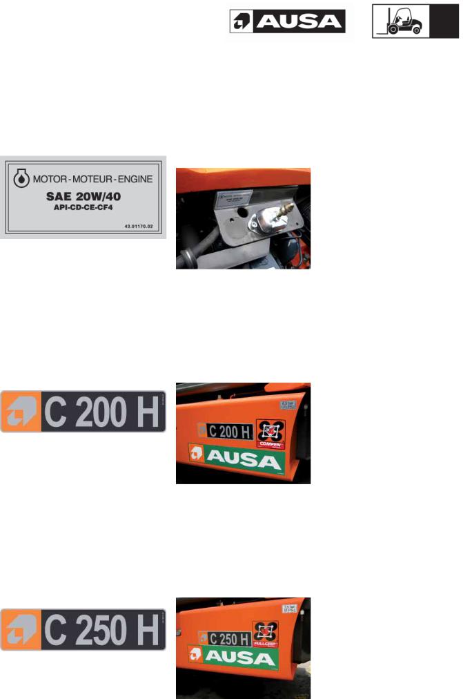
STICKER: |
|
|
|
|
|
|
|
ENGINE OIL TYPE |
|
|
|
|
|
|
|
|
|
|
|
|||
|
REFERENCE: |
DESCRIPTION: |
QUANTITY: |
||||
|
43.01170.02 |
INDICATIVE STICKER 90x45 |
1 |
||||
|
|
|
|
|
|||
|
|
|
POSITION: |
|
|||
|
|
|
On the inner cab lock, easily legible with the cab raised. |
|
|||
|
|
|
|
|
|
|
|
|
|
|
|
|
|
|
|
|
STICKER: |
|
|
|
|
|
|
|
MACHINE MODEL INDICATION (C200H / HI – C200H x4 ) |
|
|||||
|
|
|
|
||||
|
REFERENCE: |
DESCRIPTION: |
QUANTITY: |
||||
|
20.12010.01 |
INDICATIVE STICKER 68x267 MODEL C200H |
2 |
||||
|
|
|
|
|
|||
|
|
|
POSITION: |
|
|||
|
|
|
On both sides of the machine, at a distance of 0.984 in and a height of 5.906 |
||||
|
|
|
in from the lower rear corner of each tank, aligned with the bottom of the |
||||
|
|
|
tank. |
|
|||
|
|
|
|
|
|
|
|
|
|
|
|
|
|
|
|
|
STICKER: |
|
|
|
|
|
|
|
MACHINE MODEL INDICATION (C250H / HI – C250H x4) |
|
|||||
|
|
|
|
||||
|
REFERENCE: |
DESCRIPTION: |
QUANTITY: |
||||
|
20.12011.01 |
INDICATIVE STICKER 68x267 MODEL C250H |
2 |
||||
|
|
|
|
|
|||
|
|
|
POSITION: |
|
|||
|
|
|
On both sides of the machine, at a distance of 1.969 in and a height of 5.906 |
||||
|
|
|
in from the lower rear corner of each tank, aligned with the bottom of the |
||||
|
|
|
tank. |
|
|||
|
|
|
|
|
|
|
|

C200H-HI / C200H x4 / C250H-HI
28 |
C250HI LE / C250H x4 / C250H x4 LE |
|
STICKER:
MACHINE MODEL INDICATION (C250 H / HI LE)
REFERENCE: |
DESCRIPTION: |
QUANTITY: |
|
20.12017.00 |
INDICATIVE STICKER 68x267 MODEL C250H LE |
2 |
|
|
|
|
|
|
|
POSITION: |
|
|
|
On both sides of the machine, at a distance of 1.969 in and a height of 5.906 |
|
|
|
in from the lower rear corner of each tank, aligned with the bottom of the |
|
|
|
tank. |
|
|
|
|
|
|
|
|
|
STICKER: |
|
|
|
CHARACTERISTICS PLATE |
|
|
|
|
|
|
|
REFERENCE: |
DESCRIPTION: |
QUANTITY: |
|
01.00779.26 |
PLATE CHARACTERISTICS 100x130 |
1 |
|
|
|
|
|
|
|
POSITION: |
|
|
|
Riveted on top of the engine bulkhead, on its rear upper left-hand side (in |
|
|
|
forward direction of machine), in the holes prepared. Etched according to as- |
|
|
|
sembly instruction. |
|
|
|
|
|
|
|
|
|
STICKER: |
|
|
|
AUSA ANAGRAM |
|
|
|
|
|
|
|
REFERENCE: |
DESCRIPTION: |
QUANTITY: |
|
46.08099.00 |
AUSA ANAGRAM |
1 |
|
|
|
|
|
|
|
POSITION: |
|
|
|
Embedded in the cab front panel, on its outer side, in the upper left-hand part |
|
|
|
(in forward direction of machine). |
|
|
|
|
|
 Loading...