

AUO G150XVN01.0 Specification
Global LCD Panel Exchange Center
www.panelook.com
Product Specification
AU OPTRONICS CORPORATION
ʳ
ʳ
G150XVN01.0
(V) Preliminary Specification
() Final Specification
Module 15” XGA TFT-LCD Module
Model Name G150XVN01.0
Customer Date
Approved by
Note: This Specification is subject to change without
notice.
Checked &
Approved by
Date
Vito Huang 03/07/2013
Prepared by Date
Vivian Huang 03/07/2013
Audio-Video Display Business Unit /
AU Optronics corporation
document version 0.0 1/24
One step solution for LCD / PDP / OLED panel application: Datasheet, inventory and accessory!
www.panelook.com

Global LCD Panel Exchange Center
www.panelook.com
Product Specification
AU OPTRONICS CORPORATION
G150XVN01.0
Contents
1. Handling Precautions ..................................................................................................................4
2. General Description..................................................................................................................... 5
2.1 Display Characteristics ........................................................................................................................ 5
2.2 Optical Characteristics......................................................................................................................... 6
3. Functional Block Diagram...........................................................................................................9
4. Absolute Maximum Ratings...................................................................................................... 10
4.1 TFT LCD Module ............................................................................................................................. 10
4.2 Absolute Ratings of Environment ...................................................................................................... 10
5. Electrical characteristics ..........................................................................................................11
5.1 TFT LCD Module ............................................................................................................................. 11
6. Signal Characteristic ................................................................................................................. 14
6.1 Pixel Format Image ........................................................................................................................... 14
6.2 The Input Data Format ...................................................................................................................... 15
6.3 Signal Description .............................................................................................................................16
6.4 Interface Timing................................................................................................................................. 17
6.5 Power ON/OFF Sequence................................................................................................................. 19
7. Connector & Pin Assignment ...................................................................................................20
7.1 Connector .......................................................................................................................................... 20
7.2 Pin Assignmtne.................................................................................................................................. 20
8. Reliability Test............................................................................................................................ 21
9. Shipping Label............................................................................................................................22
10. Packing Form............................................................................................................................22
10.1 Packaging material .......................................................................................................................... 23
10.2 Packing instruction ..........................................................................................................................23
10.3 Palletizing........................................................................................................................................ 23
11. Outline Drawing........................................................................................................................24
document version 0.0 2/24
One step solution for LCD / PDP / OLED panel application: Datasheet, inventory and accessory!
www.panelook.com
Global LCD Panel Exchange Center
www.panelook.com
Product Specification
AU OPTRONICS CORPORATION
G150XVN01.0
Record of Revision
Version & Date Page Old Description New Description Remark
0.0 2013/03/07 All Frist Draft
document version 0.0 3/24
One step solution for LCD / PDP / OLED panel application: Datasheet, inventory and accessory!
www.panelook.com

Global LCD Panel Exchange Center
www.panelook.com
Product Specification
AU OPTRONICS CORPORATION
G150XVN01.0
1. Handling Precautions
1) Since front polarizer is easily damaged, please be cautious and not to scratch it.
2) Be sure to turn off power supply when inserting or disconnecting from input connector.
3) Wipe off water drop immediately. Long contact with water may cause discoloration or spots.
4) When the panel surface is soiled, wipe it with absorbent cotton or soft cloth.
5) Since the panel is made of glass, it may be broken or cracked if dropped or bumped on hard
surface.
6) To avoid ESD (Electro Static Discharde) damage, be sure to ground yourself before handling
TFT-LCD Module.
7) Do not open nor modify the module assembly.
8) Do not press the reflector sheet at the back of the module to any direction.
9) In case if a module has to be put back into the packing container slot after it was taken out from
the container, do not press the center of the LED light bar edge. Instead, press at the far ends
of the LED light bar edge softly. Otherwise the TFT Module may be damaged.
10) At the insertion or removal of the Signal Interface Connector, be sure not to rotate nor tilt the
Interface Connector of the TFT Module.
11) TFT-LCD Module is not allowed to be twisted & bent even force is added on module in a very short
time. Please design your display product well to avoid external force applying to module by end-user
directly.
12) Small amount of materials without flammability grade are used in the TFT-LCD module. The
TFT-LCD module should be supplied by power complied with requirements of Limited Power Source
(IEC60950 or UL1950), or be applied exemption.
13) Severe temperature condition may result in different luminance, response time and lamp ignition
voltage.
14) Continuous operating TFT-LCD display under low temperature environment may accelerate lamp
exhaustion and reduce luminance dramatically.
15) The data on this specification sheet is applicable when LCD module is placed in landscape position.
16) Continuous displaying fixed pattern may induce image sticking. It’s recommended to use screen
saver or shuffle content periodically if fixed pattern is displayed on the screen.
document version 0.0 4/24
One step solution for LCD / PDP / OLED panel application: Datasheet, inventory and accessory!
www.panelook.com
Global LCD Panel Exchange Center
www.panelook.com
Product Specification
AU OPTRONICS CORPORATION
G150XVN01.0
2. General Description
G150XVN01.0 is a Color Active Matrix Liquid Crystal Display composed of a TFT-LCD panel, a driver circuit, and a
backlight system. The screen format is intended to support the XGA (1024(H) x 768(V)) screen and 16.2M colors.
All input signal is one channel LVDS interface.
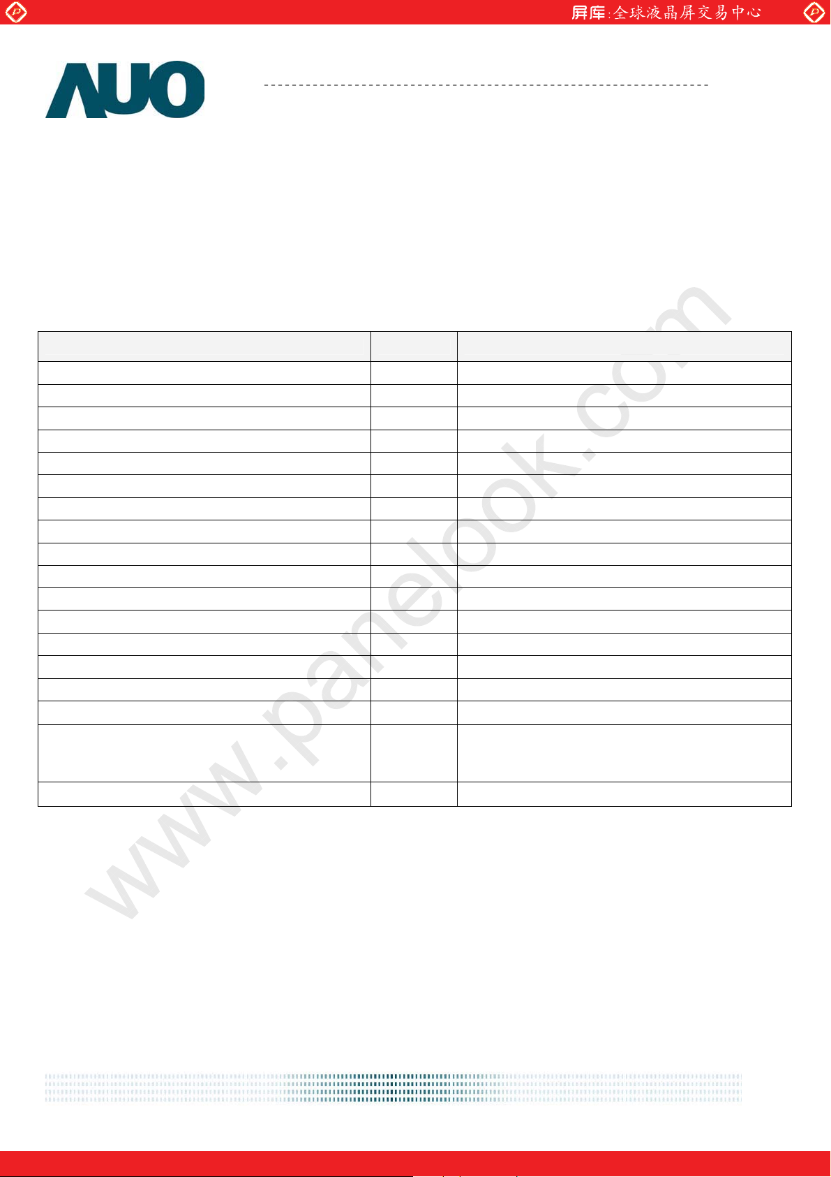
2.1 Display Characteristics
The following items are characteristics summary on the table under 25 к condition:
Items Unit Specifications
Screen Diagonal [inch] 15.0"
Active Area [mm] 304.128 (H) x 228.096 (V)
Pixels H x V 1024 x 768
Pixel Pitch [mm] 0.297 (per one triad) x 0.297
Pixel Arrangement R.G.B. Vertical Stripe
Display Mode VA, Normally Black
White Luminance [cd/m2] 300 (center, Typ)
Contrast Ratio 1500 : 1 (Typ)
Optical ResponseTime [msec] 35 (Typ, on/off)
Nominal Input Voltage VDD [Volt] +3.3
Power Consumption [Watt] TBD (Typ)
Weight [Grams] TBD
Physical Size (H x V x D) [mm] 326.5 (H) x 253.5 (V) x 9.6(D) (Typ)
Electrical Interface one channel LVDS
Surface Treatment Hard-coating (3H), Anti-Glare treatment
Support Color 16.2M / 262K colors
Temperature Range
Operating
Storage (Non-Operating)
RoHS Compliance RoHS Compliance
o
C]
[
o
[
C]
-10 to +70
-30 to +70
document version 0.0 5/24
One step solution for LCD / PDP / OLED panel application: Datasheet, inventory and accessory!
www.panelook.com
Global LCD Panel Exchange Center
www.panelook.com
Product Specification
G150XVN01.0
AU OPTRONICS CORPORATION
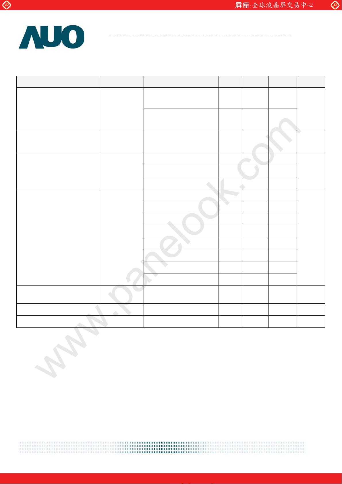
2.2 Optical Characteristics
The optical characteristics are measured under stable conditions at 25 (Room Temperature)к .
Item Unit Conditions Min. Typ. Max. Note
Horizontal (Right)
CR = 10 (Left)
Viewing Angle [degree]
Vertical (Up)
CR = 10 (Down)
Contrast Ratio Normal Direction 700 1500 -
Raising Time (TrR)
Optical Response Time [msec]
Falling Time (TrF)
Rising + Falling - 35 -
Red x
70
70
70
70
85
85
85
85
-
-
- TBD -
- TBD -
TBD TBD TBD
1
2
Color / Chromaticity
Coordinates
(CIE)
Central Luminance
Red y
Green x
Green y
Blue x
Blue y
White x
White y
2
] 240 300 - 3
[cd/m
TBD TBD TBD
TBD TBD TBD
TBD TBD TBD
TBD TBD TBD
TBD TBD TBD
0.250 0.300 0.350
0.275 0.325 0.375
Luminance Uniformity [%] 5 Points 75 - - 4,5
NTSC % - 72 -
Optical Equipment: BM-5A, BM-7, PR880, or equivalent
document version 0.0 6/24
One step solution for LCD / PDP / OLED panel application: Datasheet, inventory and accessory!
www.panelook.com
Global LCD Panel Exchange Center
p
p
www.panelook.com
Product Specification
AU OPTRONICS CORPORATION
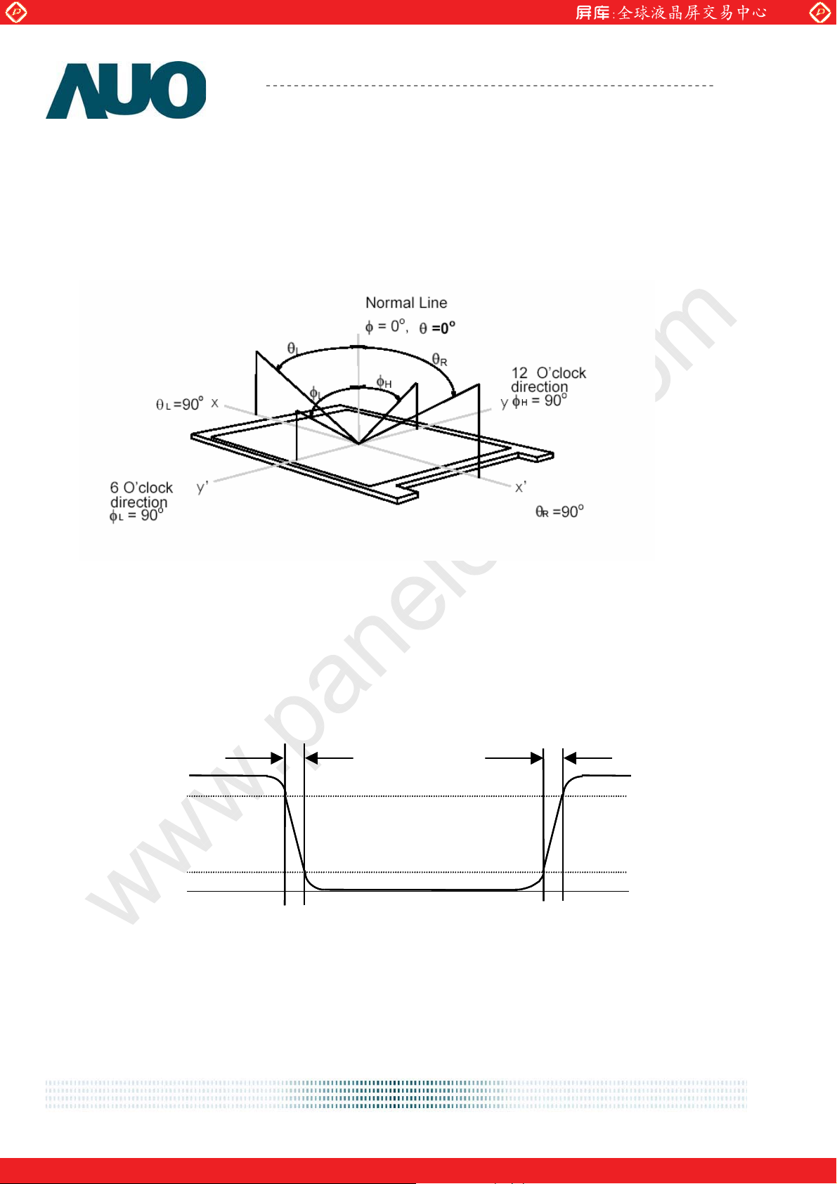
Note 1: Definition of viewing angle
Viewing angle is the measurement of contrast ratioЊ10, or Њ5, at the screen center, over a 180 horizontal and
180 vertical range (off-normal viewing angles). The 180 viewing angle range is broken down as follows; 90 (Ӱ)
horizontal left and right and 90 (ӥ) vertical, high (up) and low (down). The measurement direction is typically
perpendicular to the display surface with the screen rotated about its center to develop the desired measurement
viewing angle.
G150XVN01.0
Note 2: Definition of response time:
The output signals of photo detector are measured when the input signals are changed from “Full Black” to “Full
White” (rising time), and from “Full White” to “Full Black” (falling time), respectively. The response time is interval
between the 10% and 90% of amplitudes. Please refer to the figure as below.
O
O
tical
tical
response
response
100
100
90
90
10
10
0
0
%
%
White Black White
White Black White
Tf
F
F
Tr
Tr
R
R
document version 0.0 7/24
One step solution for LCD / PDP / OLED panel application: Datasheet, inventory and accessory!
www.panelook.com
Global LCD Panel Exchange Center
www.panelook.com
Product Specification
AU OPTRONICS CORPORATION
G150XVN01.0
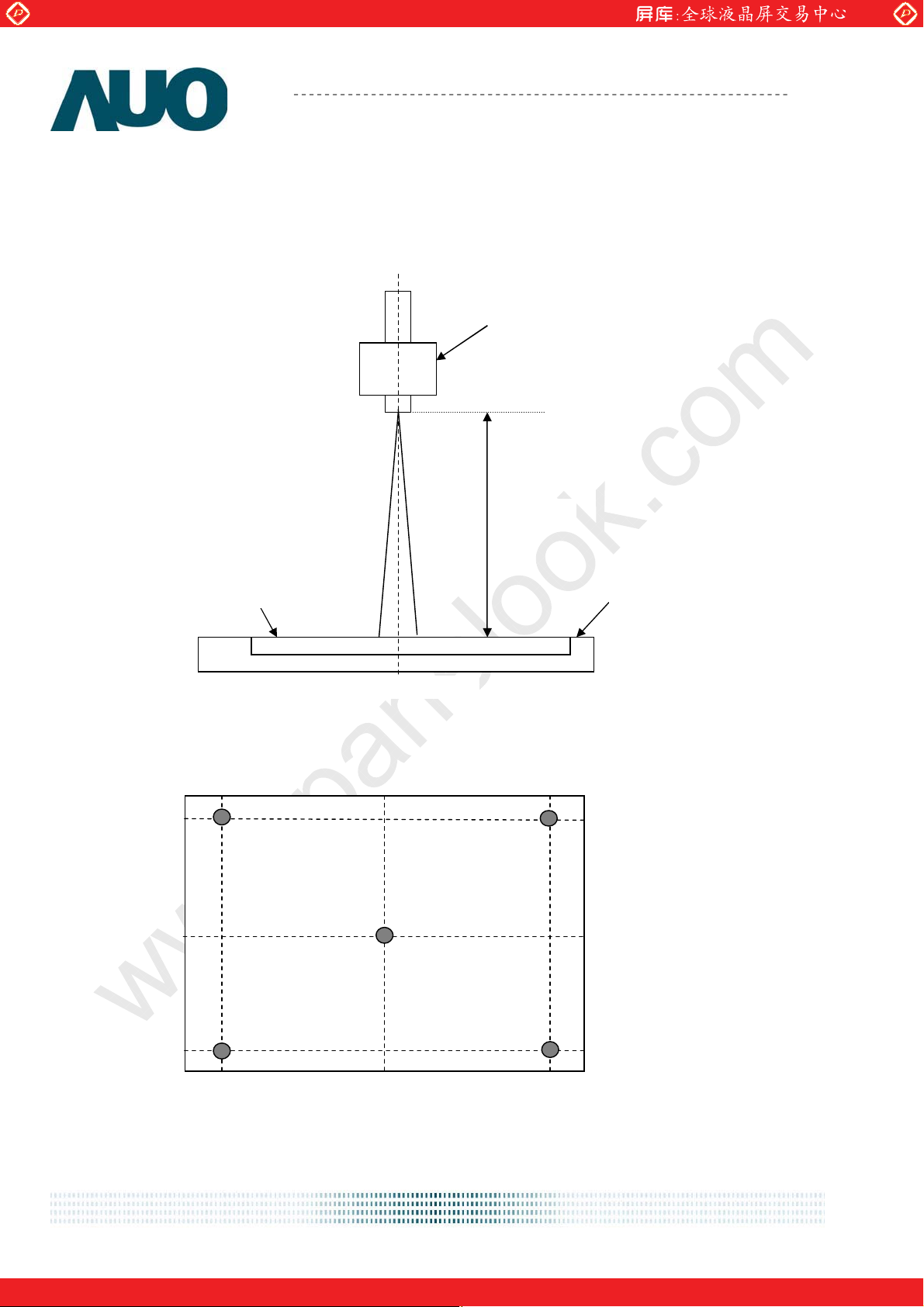
Note 3: Measurement method
The LCD module should be stabilized at given temperature for 30 minutes to avoid abrupt temperature change
during measuring. In order to stabilize the luminance, the measurement should be executed after lighting Backlight
for 30 minutes in a stable, windless and dark room. ʳ
Photo detector
Field=1
50 cm
Note 4: 5 points position
90 %
LCD Panel
Center of the screen
50 %
TFT-LCD Module
10 %
10 %
50 %
90 %
Note 5:
document version 0.0 8/24
One step solution for LCD / PDP / OLED panel application: Datasheet, inventory and accessory!
www.panelook.com
 Loading...