


B156XTN02.0
1 of 28
AU OPTRONICS CORPORATION
Product Specification
B156XTN02.0 Document Version : 0.1
(
√
√√
√
) Preliminary Specifications
(
) Final Specifications
Module 15.6”HD 16:9 Color TFT-LCD with LED Backlight design
Model Name
B156XTN02.0 (H/W:0A)
Note ( )
LED Backlight with driving circuit design
Customer Date
Checked &
Approved by
Date
Note: This Specification is subject to
change without notice.
Approved by Date
Buffy Chen
06/27/2011
Prepared by Date
Alonso JU Hsu
06/27/2011
NBBU Marketing Division
AU Optronics corporation

2 of 28
AU OPTRONICS CORPORATION
Product Specification
B156XTN02.0 Document Version : 0.1
Contents
1. Handling Precautions ....................................................................................... 4
2. General Description..........................................................................................5
2.1 General Specification .........................................................................................................5
2.2 Optical Characteristics .......................................................................................................6
3. Functional Block Diagram..............................................................................11
4. Absolute Maximum Ratings ...........................................................................12
4.1 Absolute Ratings of TFT LCD Module...............................................................................12
4.2 Absolute Ratings of Environment.....................................................................................12
5. Electrical Characteristics ............................................................................... 13
5.1 TFT LCD Module ..................................................................................................................13
5.2 Backlight Unit ......................................................................................................................15
6. Signal Interface Characteristic...................................................................... 16
6.1 Pixel Format Image ............................................................................................................16
6.2 The Input Data Format ......................................................................................................17
6.3 Integration Interface Requirement .................................................................................18
6.4 Interface Timing..................................................................................................................20
7. Panel Reliability Test .......................................................................................22
7.1 Vibration Test.......................................................................................................................22
7.2 Shock Test............................................................................................................................22
7.3 Reliability Test ......................................................................................................................22
8. Mechanical Characteristics...........................................................................23
8.1 LCM Outline Dimension.....................................................................................................23
8.2 Screw Hole Depth and Center Position..........................................................................25
9. Shipping and Package .................................................................................. 26
9.1 Shipping Label Format ......................................................................................................26
9.2 Carton Package.................................................................................................................27
9.3 Shipping Package of Palletizing Sequence...................................................................28
10. Appendix: EDID Description.........................................................................28
3 of 28
AU OPTRONICS CORPORATION
Product Specification
B156XTN02.0 Document Version : 0.1
Record of Revision
Version and Date
Page
Old description New Description Remark
0.1 2011/06/27 All First Edition for Customer

4 of 28
AU OPTRONICS CORPORATION
Product Specification
B156XTN02.0 Document Version : 0.1
1. Handling Precautions
1) Since front polarizer is easily damaged, pay attention not to scratch it.
2) Be sure to turn off power supply when inserting or disconnecting from input
connector.
3) Wipe off water drop immediately. Long contact with water may cause
discoloration or spots.
4) When the panel surface is soiled, wipe it with absorbent cotton or other soft
cloth.
5)
Since the panel is made of glass, it may break or crack if dropped or bumped
on hard surface.
6)
Since CMOS LSI is used in this module, take care of static electricity and insure
human earth when handling.
7) Do not open nor modify the Module Assembly.
8) Do not press the reflector sheet at the back of the module to any directions.
9) At the insertion or removal of the Signal Interface Connector, be sure not to
rotate nor tilt the Interface Connector of the TFT Module.
11) After installation of the TFT Module into an enclosure (Notebook PC Bezel, for
example), do not twist nor bend the TFT Module even momentary. At designing
the enclosure, it should be taken into consideration that no bending/twisting
forces are applied to the TFT Module from outside. Otherwise the TFT Module
may be damaged.
12)
Small amount of materials having no flammability grade is used in the LCD module.
The LCD module should be supplied by power complied with requirements of Limited
Power Source (IEC60950 or UL1950), or be applied exemption.
13)
Disconnecting power supply before handling LCD modules, it can prevent electric
shock, DO NOT TOUCH the electrode parts, cables, connectors and LED circuit part of
TFT module that a LED light bar build in as a light source of back light unit. It can
prevent electronic breakdown.
5 of 28
AU OPTRONICS CORPORATION
Product Specification
B156XTN02.0 Document Version : 0.1
2. General Description
B156XTN02.0 is a Color Active Matrix Liquid Crystal Display composed of a TFT LCD panel,
a driver circuit, and LED backlight system. The screen format is intended to support the
16:9 HD, 1366(H) x768(V) screen and 262k colors (RGB 6-bits data driver) with LED
backlight driving circuit. All input signals are LVDS interface compatible.
B156XTN02.0 is designed for a display unit of notebook style personal computer and
industrial machine.
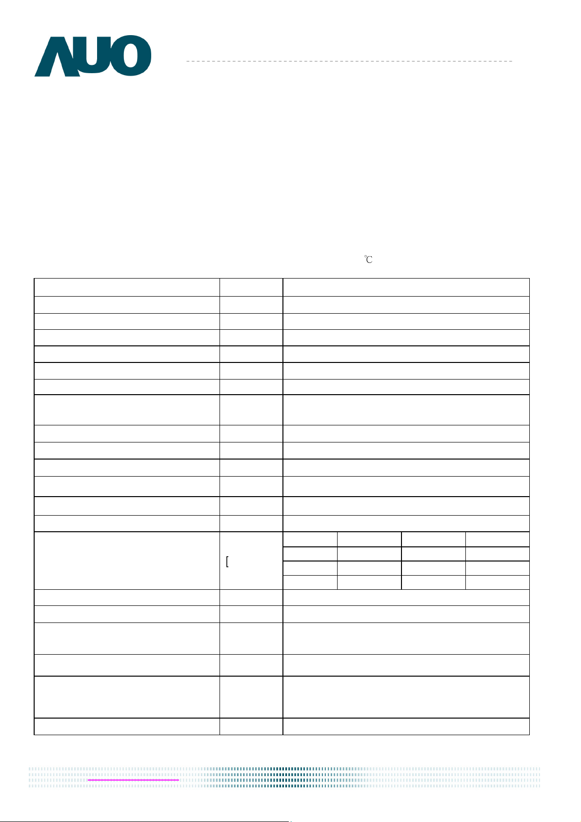
2.1 General Specification
The following items are characteristics summary on the table at 25
℃
condition:
Items Unit Specifications
Screen Diagonal [mm] 394.91
Active Area [mm] 344.23 X193.54
Pixels H x V 1366x3(RGB) x 768
Pixel Pitch [mm] 0.252X0.252
Pixel Format R.G.B. Vertical Stripe
Display Mode Normally White
White Luminance (I
LED
=25mA)
(Note: ILED is LED current)
[cd/m
2
]
220 typ. (5 points average)
187 min. (5 points average)
Luminance Uniformity 1.25 max. (5 points)
Contrast Ratio 500 typ
Response Time [ms] 16 Max
Nominal Input Voltage VDD [Volt] +3.3 typ.
Power Consumption [Watt] 5.0 max. (Include Logic and Blu power)
Weight [Grams] 450 max.
Min. Typ. Max.
Length
-
359.3
359.8
Width
-
209.5
210
Physical Size
Include bracket
[mm]
Thickne -
-
5.5
Electrical Interface 1 channel LVDS
Glass Thickness [mm] 0.5
Surface Treatment
Glare, Hardness 3H,
Reflection 4.3%
Support Color 262K colors ( RGB 6-bit )
Temperature Range
Operating
Storage (Non
-
Operating)
[
o
C]
[
o
C]
0 to +50
-20 to +60
RoHS Compliance
RoHS Compliance
6 of 28
AU OPTRONICS CORPORATION
Product Specification
B156XTN02.0 Document Version : 0.1
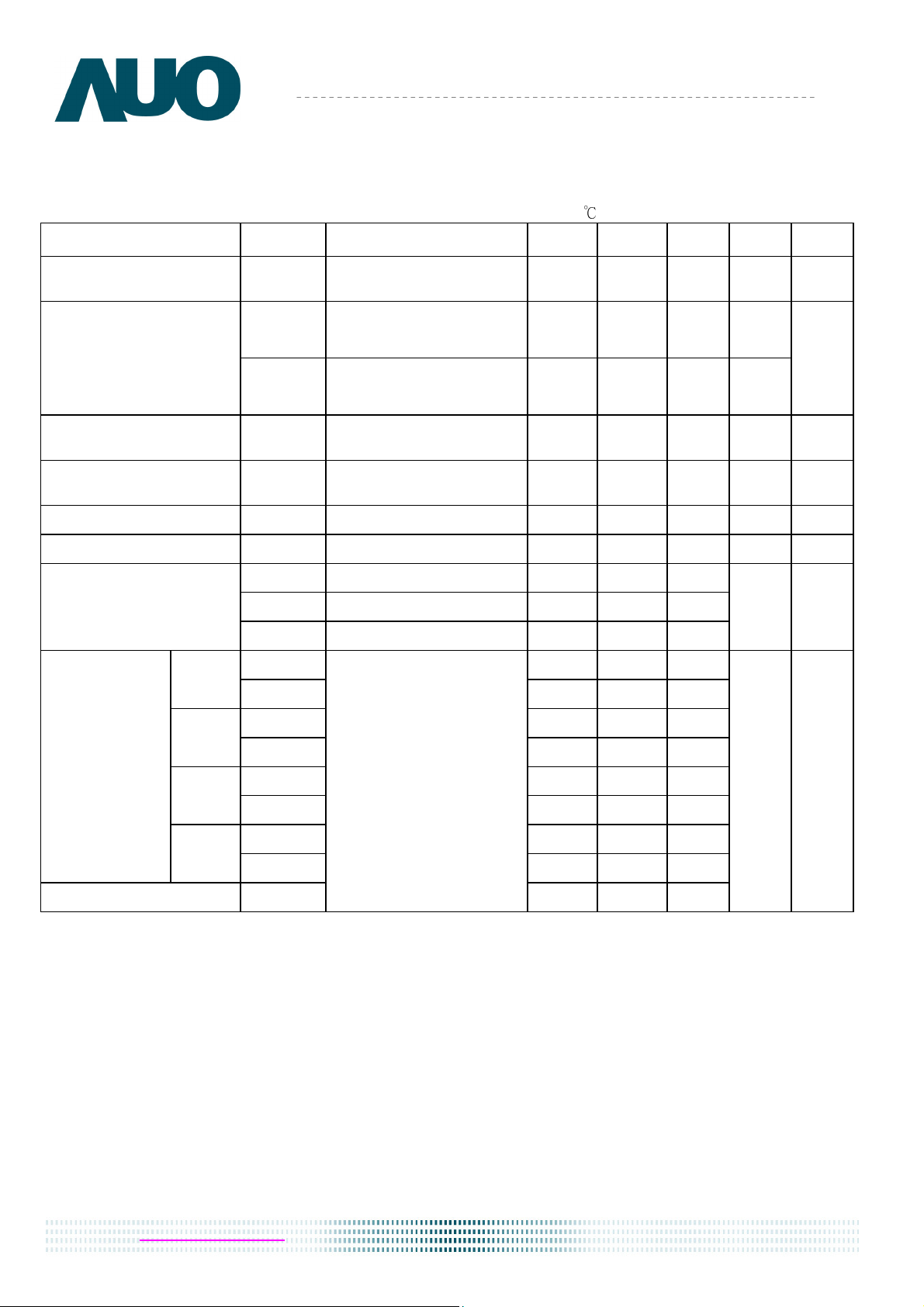
2.2 Optical Characteristics
The optical characteristics are measured under stable conditions at 25
℃
(Room Temperature) :
Item Symbol
Conditions Min. Typ. Max.
Unit Note
White Luminance
I
LED
=25mA
5 points average 187 220 -
cd/m
2
1, 4, 5.
θ
R
θ
L
Horizontal (Right)
CR = 10 (Left)
40
40
45
45
-
-
degree
Viewing Angle
ψ
H
ψ
L
Vertical (Upper)
CR = 10 (Lower)
10
30
15
35
-
-
4, 9
Luminance
Uniformity
δ
5P
5 Points
- - 1.25
1, 3, 4
Luminance
Uniformity
δ
13P
13 Points
- - 1.50
2, 3, 4
Contrast Ratio CR
- 500 -
4, 6
Cross talk %
4
4, 7
T
r
Rising
-
6
-
T
f
Falling
-
2
-
Response Time
T
RT
Rising + Falling
- 8 16
msec
4, 8
Rx
TBD TBD TBD
Red
Ry
TBD TBD TBD
Gx
TBD TBD TBD
Green
Gy
TBD TBD TBD
Bx
TBD TBD TBD
Blue
By
TBD TBD TBD
Wx
0.283
0.313
0.343
Color /
Chromaticity
Coodinates
White
Wy
0.299
0.329
0.359
NTSC %
CIE 1931
- 60 -
4

7 of 28
AU OPTRONICS CORPORATION
Product Specification
B156XTN02.0 Document Version : 0.1
Note 1: 5 points position (Ref: Active area)
1 2
3
4
5
H /4
H /4
H /4
H /4
H
W
W / 4 W / 4 W / 4 W /4
Note 2: 13 points position (Ref: Active area)
W /4
W
W /4
H
H /4
H /4
H /4
H /4
7
9
1 0
W /4
1
8
W /4
1 0
1 0
1 0
1 0
2
3
1 3
1 2
4 5
6
1 1
Note 3: The luminance uniformity of 5 or13 points is defined by dividing the maximum luminance values by
the minimum test point luminance
Note 4: Measurement method
The LCD module should be stabilized at given temperature for 30 minutes to avoid abrupt temperature
change during measuring. In order to stabilize the luminance, the measurement should be executed after
δ
W13
=
Maximum Brightness of thirteen points
Minimum Brightness of thirteen points
Maximum Brightness of five points
δ
W5
=
Minimum Brightness of five points
8 of 28
AU OPTRONICS CORPORATION
Product Specification
B156XTN02.0 Document Version : 0.1
lighting Backlight for 30 minutes in a stable, windless and dark room, and it should be measured in the
center of screen.
Note 5
:
Definition of Average Luminance of White (Y
L
):
Measure the luminance of gray level 63 at 5 points
,
Y
L
= [L (1)+ L (2)+ L (3)+ L (4)+ L (5)] / 5
L (x) is corresponding to the luminance of the point X at Figure in Note (1).
Note 6
:
Definition of contrast ratio:
Contrast ratio is calculated with the following formula.
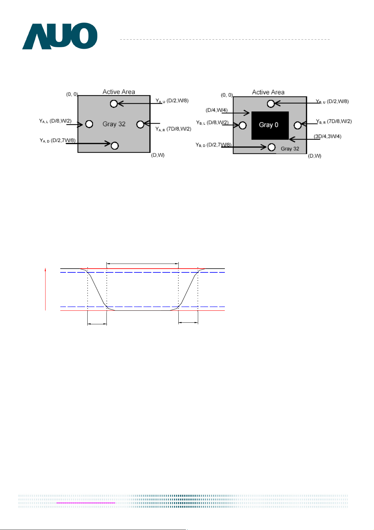
Note 7
:
Definition of Cross Talk (CT)
CT = | Y
B
– Y
A
| / Y
A
× 100 (%)
Where
Y
A
= Luminance of measured location without gray level 0 pattern (cd/m
2
)
Y
B
= Luminance of measured location with gray level 0 pattern (cd/m
2
)
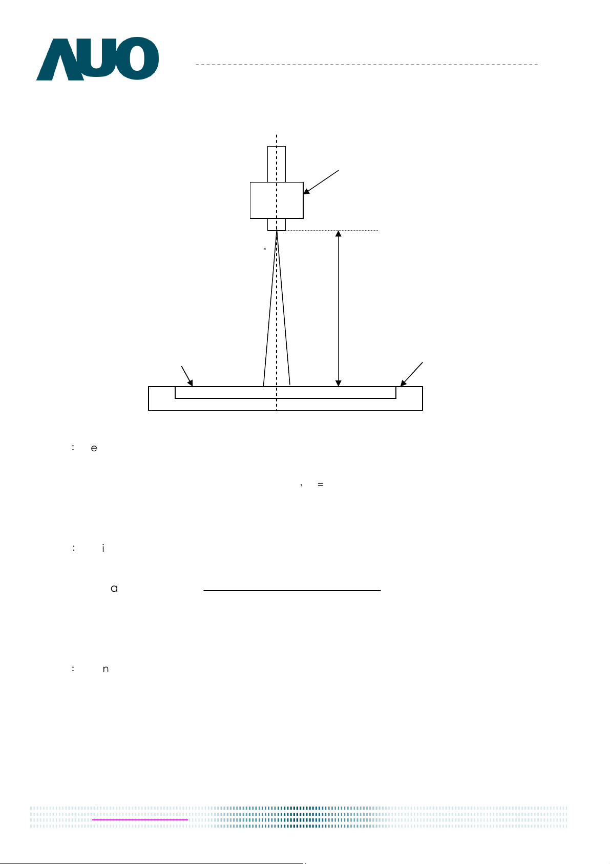
-
Photo detector
Field=2
°
Contrast ratio (CR)=
Brightness on the “White” state
Brightness on the “Black” state
9 of 28
AU OPTRONICS CORPORATION
Product Specification
B156XTN02.0 Document Version : 0.1
Note 8: Definition of response time:
The output signals of BM-7 or equivalent are measured when the input signals are changed from “Black”
to “White” (falling time) and from “White” to “Black” (rising time), respectively. The response time interval
between the 10% and 90% of amplitudes. Refer to figure as below.
S
i
g
n
a
l
(
R
e
l
a
t
i
v
e
v
a
l
u
e
)
"Black"
Tr
Tf
"White""White"
0%
10%
90%
100%
 Loading...