

AUO G121STN01.0 Specification
( )
Preliminary Specifications
(
V ) Final Specifications
G121STN01.0
Module 12.1 I
nch Color TFT-LCD
Model Name G121STN01.0
Customer Date
Checked &
Approved by
Approved by Date
Leader Feng
Prepared by
2012/11/21
Note: This Specification is subject to change
without notice.
Yichih Chen 2012/11/21
General Display Business Division /
AU Optronics corporation
G121STN01.0 rev. 1.23
P
age 1/24
G121STN01.0
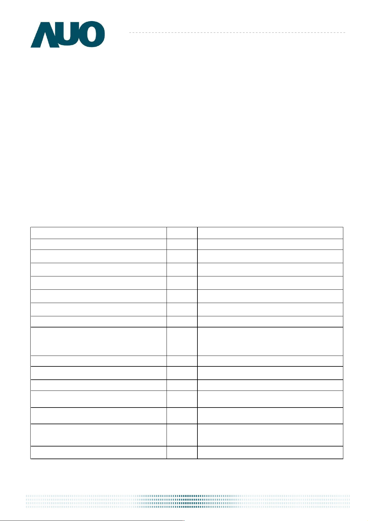
Contents
1. Operating Precautions.....................................................................................
4
2. General Description.........................................................................................5
2.1 Display Characteristics...........................................................................................................5
2.2 Optical Characteristics ...........................................................................................................6
3. Functional Block Diagram ...............................................................................9
4. Absolute Maximum Ratings ..........................................................................10
4.1 Absolute Ratings of TFT LCD Module .................................................................................10
4.2 Absolute Ratings of Environment ........................................................................................10
5. Electrical Characteristics ..............................................................................11
5.1 TFT LCD Module.................................................................................................................. 11
5.2 Backlight Unit........................................................................................................................13
6. Signal Characteristics ...................................................................................14
6.1 Pixel Format Image ..............................................................................................................14
6.2 Scanning Direction ...............................................................................................................14
6.3 TFT-LCD Interface Signal Description .................................................................................15
6.4 The Input Data Format .........................................................................................................16
6.5 TFT-LCD Interface Timing ....................................................................................................17
6.6 Power ON/OFF Sequence ...................................................................................................18
7. Connector & Pin Assignment........................................................................19
7.1 TFT-LCD Signal (CN1): LCD Connector .............................................................................19
7.2 LED Backlight Unit (CN2): Backlight Connector .................................................................19
8. Reliability Test Criteria ..................................................................................20
9. Mechanical Characteristics ...........................................................................21
9.1 LCM Outline Dimension (Front View) ..................................................................................21
9.2 LCM Outline Dimension (Rear View)(Pin 1 position) ..........................................................22
10. Label and Packaging....................................................................................23
10.1 Shipping Label (on the rear side of TFT-LCD display)......................................................23
10.2 Carton Package .................................................................................................................23
11 Safety.............................................................................................................24
11.1 Sharp Edge Requirements.................................................................................................24
11.2 Materials .............................................................................................................................24
11.3 Capacitors...........................................................................................................................24
11.4 National Test Lab Requirement..........................................................................................24
G121STN01.0 rev. 1.23
P
age 2/24
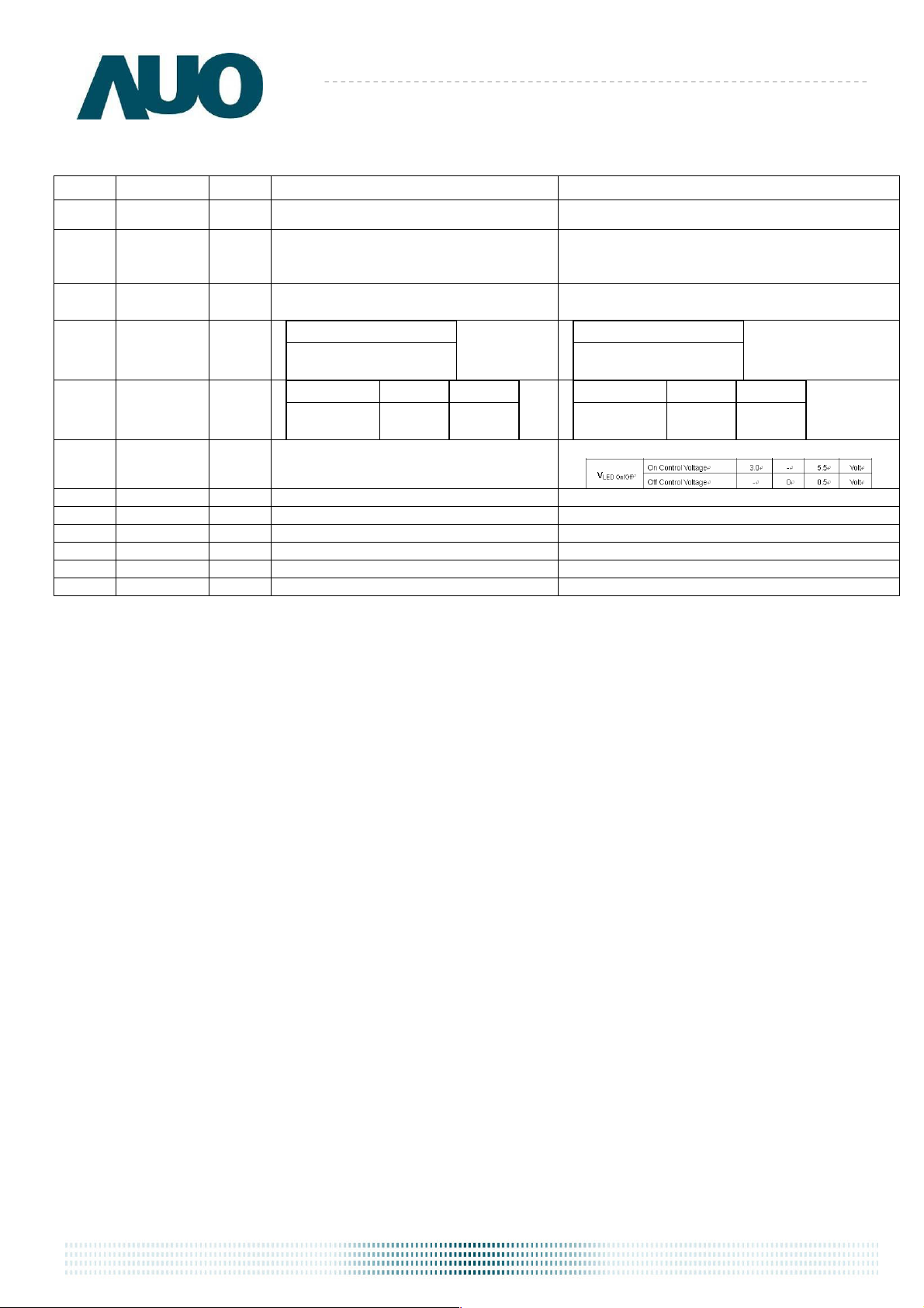
Version
Record of Revision
G121STN01.0
Date Page
1.0 2012/06/06
1.1 2012/08/12
1.2 2012/08/28
1.21 2012/09/12
1.22 2012/10/01
All First Edition
6
21, 22
23
10
6
IF= 80mA/1 LED Line
(center point)
6
Luminance
Old description New D
1. Color / Chromaticity Coordinates updated
n/a
2. Outline Dimension updated
3. Shipping Label updated
Operation Humidity:95%
Storage Humidity: 95%
Conditions
IF= 60mA/1 LED Line
(center point)
Item Unit Min.
White
Luminance
Item
White
Unit
[cd/m2]
Min.
240
Operation Humidity:90%
Storage Humidity: 90%
Conditions
[cd/m2]
Add LED on/off voltage range
1.23 2012/11/21
13
escription
250
G121STN01.0 rev. 1.23
P
age 3/24

1. Operating Precautions
1)
Since front polarizer is easily damaged, please be cautious and not to scratch it.
Be sure to turn off power supply when inserting or disconnecting from input connector.
2)
G121STN01.0
3)
Wipe
off
water drop immediately. Long contact with water may cause discoloration or
spots.
4) When the panel surface is soiled, wipe it with absorbent cotton or soft cloth.
5) Since the panel is made of glass, it may be broken or cracked if dropped or bumped on
hard surface.
6) To avoid ESD (Electro Static Discharde) damage, be sure to ground yourself before handling
TFT-LCD Module.
7) Do not open nor modify the module assembly.
8) Do not press the reflector sheet at the back of the module to any direction.
9) In case if a module has to be put back into the packing container slot after it was taken
out from the container, do not press the center of the LED light bar edge. Instead, press
at the far ends of the LED light bar edge softly. Otherwise the TFT Module may be
damaged.
10) At the insertion or removal of the Signal Interface Connector, be sure not to rotate nor
tilt the Interface Connector of the TFT Module.
11) TFT-LCD Module is not allowed to be twisted & bent even force is added on module in a very
short time. Please design your display product well to avoid external force applying to module
by end-user directly.
12) Small amount of materials without flammability grade are used in the TFT-LCD module. The
TFT-LCD module should be supplied by power complied with requirements of Limited Power
Source (IEC60950 or UL1950), or be applied exemption.
13) Severe temperature condition may result in different luminance, response time and lamp
ignition voltage.
14) Continuous operating TFT-LCD display under low temperature environment may accelerate
lamp exhaustion and reduce luminance dramatically.
15) The data on this specification sheet is applicable when LCD module is placed in landscape
position.
16) Continuous displaying fixed pattern may induce image sticking. It’s recommended to use
screen saver or shuffle content periodically if fixed pattern is displayed on the screen.
G121STN01.0 rev. 1.23
P
age 4/24
G121STN01.0
2. General Description
This specification applies to the Color Active Matrix Liquid Crystal Display G121STN01.0
composed of a TFT-LCD display, a driver and power supply circuit, and a LED backlight system.
The screen format is intended to support SVGA (800(H) x 600(V)) screen and 16.2M (RGB
8-bits) or 262k colors (RGB 6-bits).
LED driving board for backlight unit is included in G121STN01.0 and the LED unit is replaceable.
All input signals are LVDS interface and compatible with G121SN01 V4. G121STN01.0 designed
with wide viewing angle; wide temperature and long life LED backlight is well suited for industial
applications.
G121STN01.0 is a RoHS product.
2.1 Display Characteristics
he
llowing items are characteristics summary on the table under 25 ℃ condition:
fo
T
Items Unit Specifications
Screen Diagonal [inch] 12.1
Active Area [mm] 246 (H) x 184.5 (V)
Pixels H x V 800 x 3(RGB) x 600
Pixel Pitch [mm] 0.3075 x 0.3075
Pixel Arrangement R.G.B. Vertical Stripe
Display Mode TN, Normally White
Nominal Input Voltage VDD [Volt] 3.3 (typ.)
Typical Power Consumption [Watt]
Weight [Grams] 580 (Max.)
Physical Size [mm] 279.0(H) x 209.0(V) x 9.0(D) (Typ.)
Electrical Interface 1 channel LVDS
4.61 W (typ.)
All black pattern
Surface Treatment Anti-glare, Hardness 3H
Support Color 16.2M / 262K colors
Temperature Range
Operating
Storage (Non-Operating)
RoHS Compliance RoHS Compliance
[oC]
[oC]
-30 to +85
-30 to +85
G121STN01.0 rev. 1.23
P
age 5/24
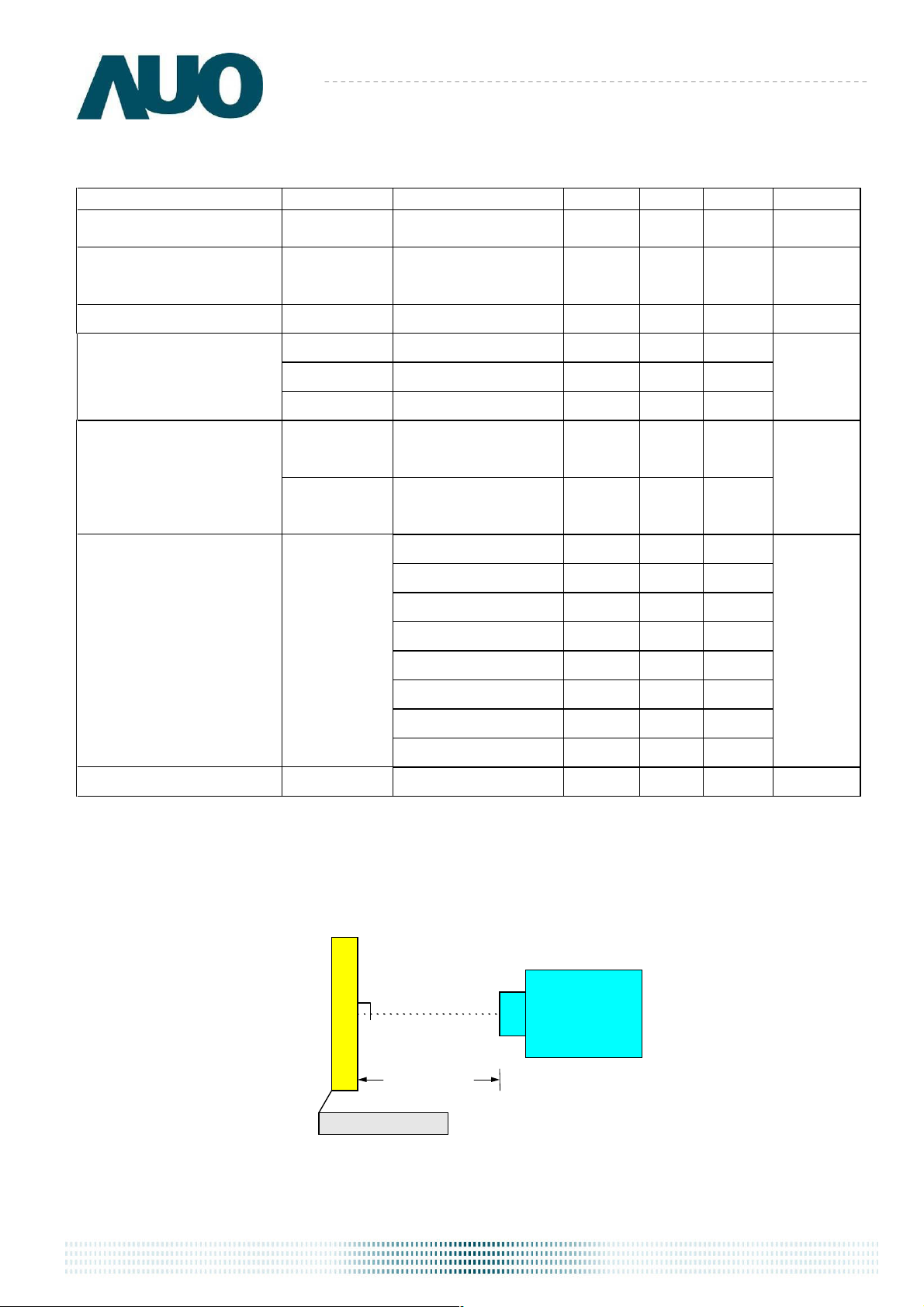
Measuring distance
2.2 Optical Characteristics
The o
ptical characteristics are measured under stable conditions at 25 (Room Temperature):℃
Item Unit Conditions Min. Typ. Max. Remark
White Luminance [cd/m2]
IF= 60mA/1 LED Line
(center point)
250 300 - Note 1
G121STN01.0
Uniformity
Contrast Ratio
Response Time
Viewing Angle
Color / Chromaticity
Coordinates
(CIE 1931)
Color Gamut %
%
5 Points
500
[msec] Rising
[msec] Falling
[msec]
[degree]
[degree]
[degree]
[degree]
Raising + Falling
Horizontal (Right)
CR = 10
Vertical
CR = 10 (Lower)
Red x
Red y
Green x
Green y
Blue x
Blue y
White x
White y
(Left)
(Upper)
75
-
-
-
70
70
55
65
-
600
25
10
35
80
80
65
75
Note 2, 3
-
-
35
20
55
-
-
-
-
0.550 0.600 0.650
0.295 0.345 0.395
0.281 0.331 0.381
0.558 0.608 0.658
0.105 0.155 0.205
0.037 0.087 0.137
0.263 0.313 0.363
0
.279 0.329 0.379
55 -
Note 4
Note 5
Note 6
Note 1: Measurement method
Equi
Aperture 1 with 50cm viewing dist∘ ance
Test Point Center
Environment < 1 lux
pment Pattern Generator, Power Supply, Digital Voltmeter, Luminance meter (SR_3 or equivalent)
LCD Module
SR_3 or
equivalent
Module Driving Equipment
G121STN01.0 rev. 1.23
P
age 6/24
Minimum
Brightnes
s of
five
poin
ts
=
Maximum
Brightness of
five
points
Contrast ratio (CR)=
Brightness on the “White” state
Brightness on the “Black” state
Tr
Tr
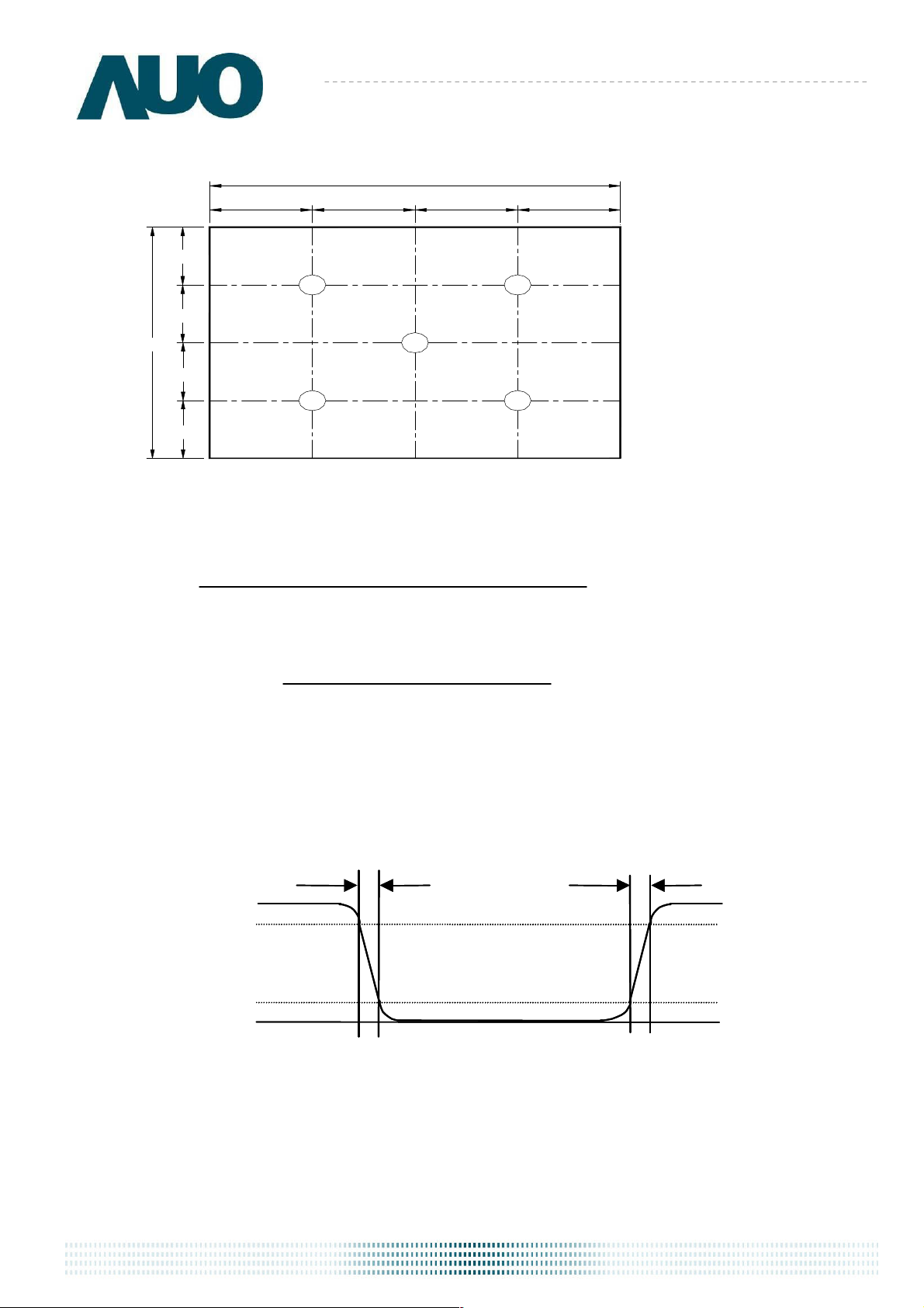
Note 2: Definition of 5 points position (Display active area: 246mm (H) x 184.5mm (V))
W
W / 4 W / 4 W / 4 W / 4
H / 4
1 2
H / 4
G121STN01.0
H
H / 4
4 5
H / 4
3: The luminance uniformity of 5 points is defined by dividing the minimum luminance values by the
Note
maximum test point luminance
δ
Note 4: Definition of contrast ratio (CR):
W9
3
Note 5: Definition of response time:
The ou
tput signals of photo detector are measured when the input signals are changed from “White” to
“Black” (falling time) and from “Black” to “White” (rising time), respectively. The response time interval is
between 10% and 90% of amplitudes. Please refer to the figure as below.
Optical
Optical
response
response
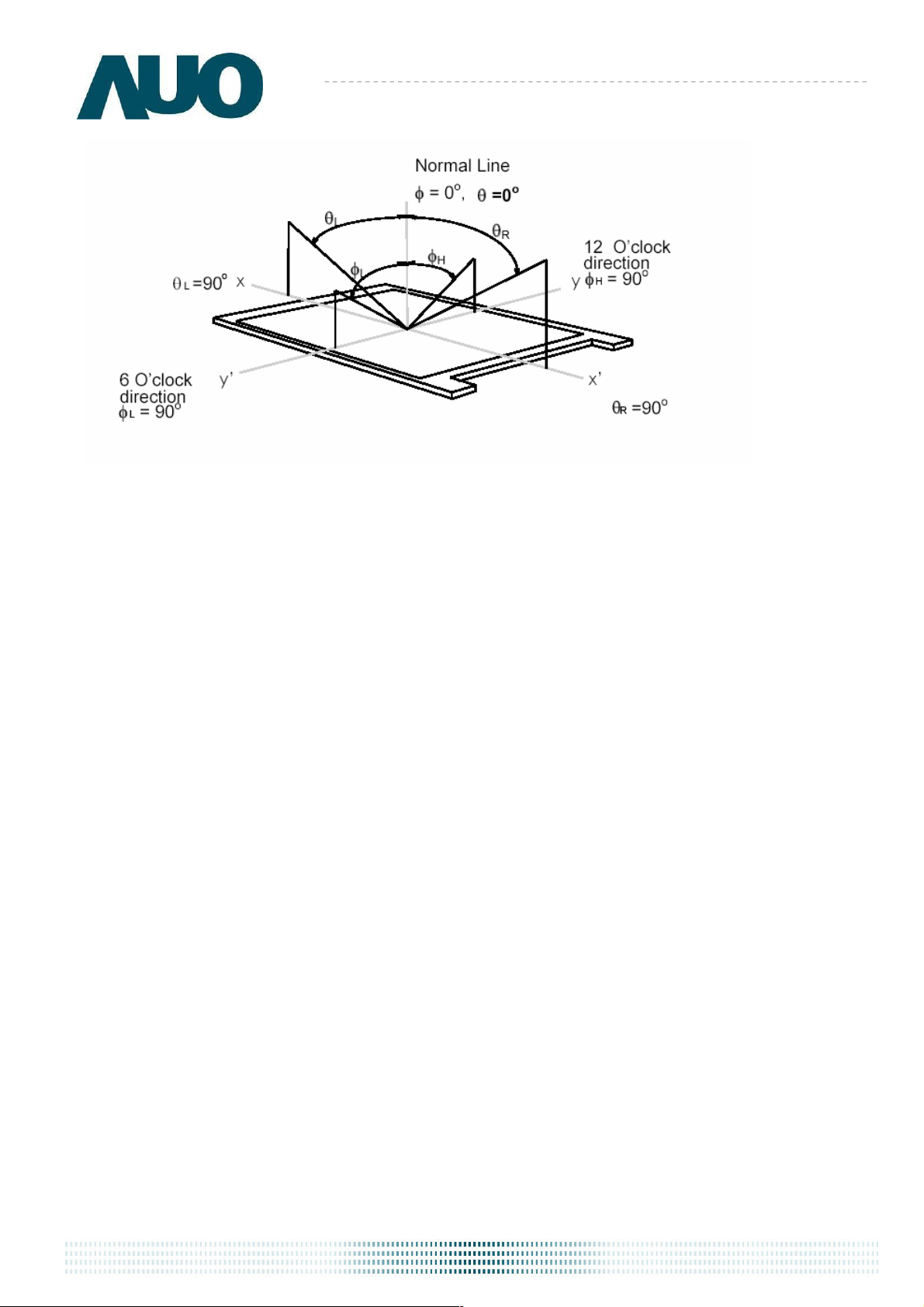
Note 6: Definition of viewing angle
Viewing angle is the measurement of contrast ratio 10, at the screen center, over a 180° horizontal and ≧
180° vertical range (off-normal viewing angles). The 180° viewing angle range is broken down as below:
90° (θ) horizontal left and right, and 90° (Φ) vertical high (up) and low (down). The measurement direction is
typically perpendicular to the display surface with the screen rotated to its center to develop the desired
measurement viewing angle.
%
100
90
90
10
10
Tf
White
White
0
0
Black
Black
White
White
G121STN01.0 rev. 1.23
P
age 7/24
G121STN01.0
G121STN01.0 rev. 1.23
P
age 8/24
 Loading...