

Page 1
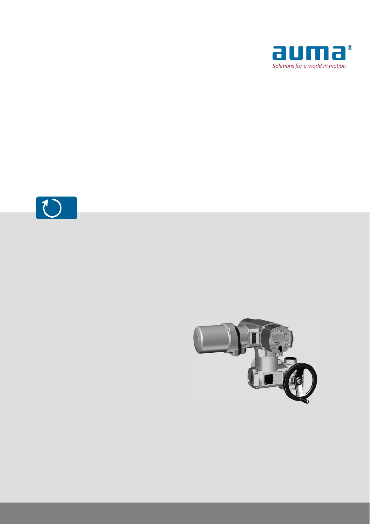
Multi-turn actuators
SA 07.2 – SA 16.2
SAR 07.2 – SAR 16.2
Control unit: electronic (MWG)
with actuator controls
AUMATIC AC 01.2 Non-Intrusive
Control
Parallel
Profibus DP
→ Modbus TCP/IP
Foundation Fieldbus
Assembly, operation, commissioningOperation instructions
Page 2

SA 07.2 – SA 16.2 / SAR 07.2 – SAR 16.2 Control unit: electronic (MWG)
Table of contents AC 01.2 Non-Intrusive Modbus TCP/IP
Read operation instructions first.
●
Observe safety instructions.
●
These operation instructions are part of the product.
●
Retain operation instructions during product life.
●
Pass on instructions to any subsequent user or owner of the product.
Purpose of the document:
This document contains information for installation, commissioning, operation and maintenance staff . It is intended
to support device installation and commissioning.
Reference documents:
Reference documents can be downloaded from the Internet (www.auma.com) or ordered directly from AUMA
(refer to <Addresses>).
Table of contents Page
51. Safety instructions.................................................................................................................
51.1. Basic information on safety
51.2. Range of application
61.3. Applications in Ex zone 22 (option)
61.4. Warnings and notes
71.5. References and symbols
82. Identification...........................................................................................................................
82.1. Name plate
102.2. Short description
113. Transport, storage and packaging........................................................................................
113.1. Transport
113.2. Storage
113.3. Packaging
124. Assembly................................................................................................................................
124.1. Mounting position
124.2. Handwheel fitting
124.3. Multi-turn actuator: mount to valve/gearbox
124.3.1. Output drive types B, B1 – B4 and E
134.3.1.1. Multi-turn actuator (with output drive types B1 – B4 or E): mount to valve/gearbox
134.3.2. Output drive type A
144.3.2.1. Stem nut: finish machining
154.3.2.2. Multi-turn actuator (with output drive type A): mount to valve
164.4. Accessories for assembly
164.4.1. Stem protection tube for rising valve stem
164.5. Mounting positions of local controls
174.5.1. Mounting positions: modify
185. Electrical connection.............................................................................................................
185.1. Basic information
195.2. Connection with AUMA plug/socket connector
195.2.1. Terminal compartment: open
205.2.2. Cable connection
225.2.3. Terminal compartment: close
2
Page 3

SA 07.2 – SA 16.2 / SAR 07.2 – SAR 16.2 Control unit: electronic (MWG)
AC 01.2 Non-Intrusive Modbus TCP/IP Table of contents
225.2.4. Bus terminal compartment: open
235.2.5. Industrial Ethernet cable: connect
245.2.6. Bus terminal compartment: close
245.3. Accessories for electrical connection
245.3.1. Controls mounted on wall bracket
255.3.2. Parking frame
265.3.3. Protection cover
265.3.4. Double sealed intermediate frame
265.3.5. External earth connection
286. Operation................................................................................................................................
286.1. Manual operation
286.1.1. Manual operation: engage
286.1.2. Manual operation: disengage
286.2. Motor operation
286.2.1. Local actuator operation
296.2.2. Actuator operation from remote
296.3. Menu navigation via push buttons (for settings and indications)
306.3.1. Menu layout and navigation
316.4. User level, password
326.4.1. Password entry
326.4.2. Password change
336.5. Language in the display
336.5.1. Language change
357. Indications..............................................................................................................................
357.1. Indications during commissioning
357.2. Indications in the display
367.2.1. Feedback indications from actuator and valve
397.2.2. Status indications according to AUMA classification
407.2.3. Status indications according to NAMUR recommendation
417.3. Mechanical position indicator/running indication
427.4. Indication lights
438. Signals.....................................................................................................................................
438.1. Status signals via output contacts (digital outputs)
438.1.1. Assignment of outputs
438.1.2. Coding the outputs
438.2. Analogue signals
449. Commissioning (basic settings)...........................................................................................
449.1. Type of seating: set
459.2. Torque switching: set
469.3. Limit switching: set
489.4. Bus address (slave address), baud rate, parity and monitoring time: set
499.4.1. Modbus TCP/IP Gateway: set
499.5. Test run
499.5.1. Direction of rotation: check
509.5.2. Limit switching: check
509.6. Switch compartment: open
519.7. Mechanical position indicator: set
519.8. Gear stage of the reduction gearing: test/set
539.9. Switch compartment: close
3
Page 4

SA 07.2 – SA 16.2 / SAR 07.2 – SAR 16.2 Control unit: electronic (MWG)
Table of contents AC 01.2 Non-Intrusive Modbus TCP/IP
5410. Corrective action....................................................................................................................
5410.1. Faults during commissioning
5410.2. Fault indications and warning indications
5710.3. Fuses
5710.3.1. Fuses within the actuator controls
5910.3.2. Motor protection (thermal monitoring)
6011. Servicing and maintenance...................................................................................................
6011.1. Preventive measures for servicing and safe operation
6011.2. Maintenance
6111.3. Disposal and recycling
6212. Technical data.........................................................................................................................
6212.1. Technical data Multi-turn actuators
6412.2. Technical data Actuator controls
7013. Spare parts.............................................................................................................................
7013.1. Spare parts list SA 07.2 – SA 16.2/SAR 07.2 – SAR 16.2
7213.2. AUMATIC AC 01.2 actuator controls with AUMA plug/socket connector (SFH)
7414. Certificates..............................................................................................................................
7414.1. Declaration of Incorporation and EC Declaration of Conformity
75Index........................................................................................................................................
77Addresses...............................................................................................................................
4
Page 5

SA 07.2 – SA 16.2 / SAR 07.2 – SAR 16.2 Control unit: electronic (MWG)
AC 01.2 Non-Intrusive Modbus TCP/IP Safety instructions
1. Safety instructions
1.1. Basic information on safety Standards/directives
Safety instructions/warn-
ings
Qualification of staff
Commissioning
Operation
Protective measures
AUMA products are designed and manufactured in compliance with recognised
standards and directives.This is certified in a Declaration of Incorporation and an
EC Declaration of Conformity.
The end user or the contractor must ensure that all legal requirements, directives,
guidelines, national regulations and recommendations with respect to assembly,
electrical connection, commissioning and operation are met at the place of installation.
All personnel working with this device must be familiar with the safety and warning
instructions in this manual and observe the instructions given. Safety instructions
and warning signs on the device must be observed to av oid personal injury or property
damage.
Assembly, electrical connection, commissioning, operation, and maintenance must
be carried out exclusively by suitab ly qualified personnel ha ving been authorised by
the end user or contractor of the plant only.
Prior to working on this product, the staff must have thoroughly read and understood
these instructions and, furthermore, know and observe officially recognised rules
regarding occupational health and safety.
Prior to commissioning, it is important to check that all settings meet the requirements
of the application. Incorrect settings might present a danger to the application, e.g.
cause damage to the valve or the installation.The manufacturer will not be held
liable for any consequential damage. Such risk lies entirely with the user.
Prerequisites for safe and smooth operation:
●
Correct transport, proper storage, mounting and installation, as well as careful
commissioning.
●
Only operate the device if it is in perf ect condition while observing these instructions.
●
Immediately report any faults and damage and allow for corrective measures.
●
Observe recognised rules for occupational health and safety.
●
Observe the national regulations.
●
During operation, the housing warms up and surface temperatures > 60 °C may
occur.To prevent possible burns, we recommend checking the surf ace temperature using an appropriate thermometer and wearing protective gloves, if required, prior to working on the device.
The end user or the contractor are responsible for implementing required protective
measures on site, such as enclosures, barriers, or personal protective equipment
for the staff.
Maintenance
T o ensure saf e device operation, the maintenance instructions included in this manual
must be observed.
Any device modification requires prior consent of the manufacturer.
1.2. Range of application
AUMA multi-turn actuators are designed for the operation of industrial valves, e.g.
globe valves, gate valves, butterfly valves, and ball valves.
Other applications require explicit (written) confirmation by the manufacturer.
The following applications are not permitted, e.g.:
●
●
●
●
Industrial trucks according to EN ISO 3691
Lifting appliances according to EN 14502
Passenger lifts according to DIN 15306 and 15309
Service lifts according to EN 81-1/A1
5
Page 6

SA 07.2 – SA 16.2 / SAR 07.2 – SAR 16.2 Control unit: electronic (MWG)
Safety instructions AC 01.2 Non-Intrusive Modbus TCP/IP
●
Escalators
●
Continuous duty
●
Buried service
●
Continuous submersion (observe enclosure protection)
●
Potentially explosive areas, with the exception of zone 22
●
Radiation exposed areas in nuclear power plants
No liability can be assumed for inappropriate or unintended use.
Observance of these operation instructions is considered as part of the device's
designated use.
Information
These operation instructions are only valid for the "clockwise closing" standard
version, i.e. driven shaft turns clockwise to close the valve.
1.3. Applications in Ex zone 22 (option)
Actuators of the indicated series basically meet the requirements for applications in
dust hazardous locations of ZONE 22 in compliance with the A TEX directiv e 94/9/EC.
The actuators are designed to meet enclosure protection IP68 and fulfil the
requirements of EN 50281-1-1:1998 section 6 - Electrical apparatus for use in
presence of combustible dust, requirements for category 3 electrical equipment protected by enclosures.
To comply with all requirements of EN 50281-1-1:1998, it is imperative that the
following points are observed:
●
In compliance with the A TEX directiv e 94/9/EC, the actuators must be equipped
with an additional identification – II3D IP6X T150 °C.
●
The maximum surface temperature of the actuators, based on an ambient
temperature of +40 °C in accordance with EN 50281-1-1 section 10.4, is +150
°C. In accordance with section 10.4, an increased dust deposit on the equipment
was not considered for the determination of the maximum surface temper ature.
●
The correct connection of the thermoswitches or the PTC thermistors as well
as fulfilling the requirements of the duty type and the technical data are prerequisites for compliance with the maximum surface temperature of devices.
●
The connection plug may only be plugged in or pulled out when device is disconnected from the mains.
●
The cable glands used also have to meet the requirements of category II3 D
and must at least comply with enclosure protection IP67.
●
The actuators must be connected by means of an external ground connection
(accessory part) to the potential compensation or integrated into an earthed
piping system.
●
The threaded plug (part no. 511.0) or the stem protection tube with protective
cap (part nos. 568.1 and 568.2) for sealing the hollow shaft must imperatively
be mounted to guarantee tightness and therefore the combustible dust hazard
protection.
●
As a general rule, the requirements of EN 50281-1-1 must be respected in dust
hazardous locations. During commissioning, service, and maintenance, special
care as well as qualified and trained personnel are required for the saf e operation
of actuators.
1.4. Warnings and notes
The following warnings draw special attention to saf ety-rele v ant procedures in these
operation instructions, each marked by the appropriate signal word (DANGER,
WARNING, CAUTION, NOTICE).
Indicates an imminently hazardous situation with a high level of risk. Failure
to observe this warning could result in death or serious injury.
6
Page 7
SA 07.2 – SA 16.2 / SAR 07.2 – SAR 16.2 Control unit: electronic (MWG)
AC 01.2 Non-Intrusive Modbus TCP/IP Safety instructions
Indicates a potentially hazardous situation with a medium level of risk. F ailure
to observe this warning could result in death or serious injury.
Indicates a potentially hazardous situation with a low level of risk. Failure to
observe this warning may result in minor or moderate injury . Ma y also be used
with property damage.
Potentially hazardous situation. Failure to observe this warning may result in
property damage. Is not used for personal injury.
Arrangement and typographic structure of the warnings
Type of hazard and respective source!
Potential consequence(s) in case of non-observance (option)
→
Measures to avoid the danger
→
Further measure(s)
Safety alert symbol warns of a potential personal injury hazard.
The signal word (here: DANGER) indicates the level of hazard.
1.5. References and symbols
The following references and symbols are used in these instructions:
Information The term Information preceding the text indicates important notes and information.
Symbol for CLOSED (valve closed)
Symbol for OPEN (valve open)
Important information before the next step.This symbol indicates what is required
for the next step or what has to be prepared or observed.
Via the menu to parameter
Describes the path within the menu to the parameter. By using the push buttons of
the local controls you may quickly find the desired parameter in the display.
< > Reference to other sections
T erms in brack ets shown abov e refer to other sections of the document which provide
further information on this topic.These terms are either listed in the index, a heading
or in the table of contents and may quickly be found.
7
Page 8
SA 07.2 – SA 16.2 / SAR 07.2 – SAR 16.2 Control unit: electronic (MWG)
Identification AC 01.2 Non-Intrusive Modbus TCP/IP
2. Identification
2.1. Name plate
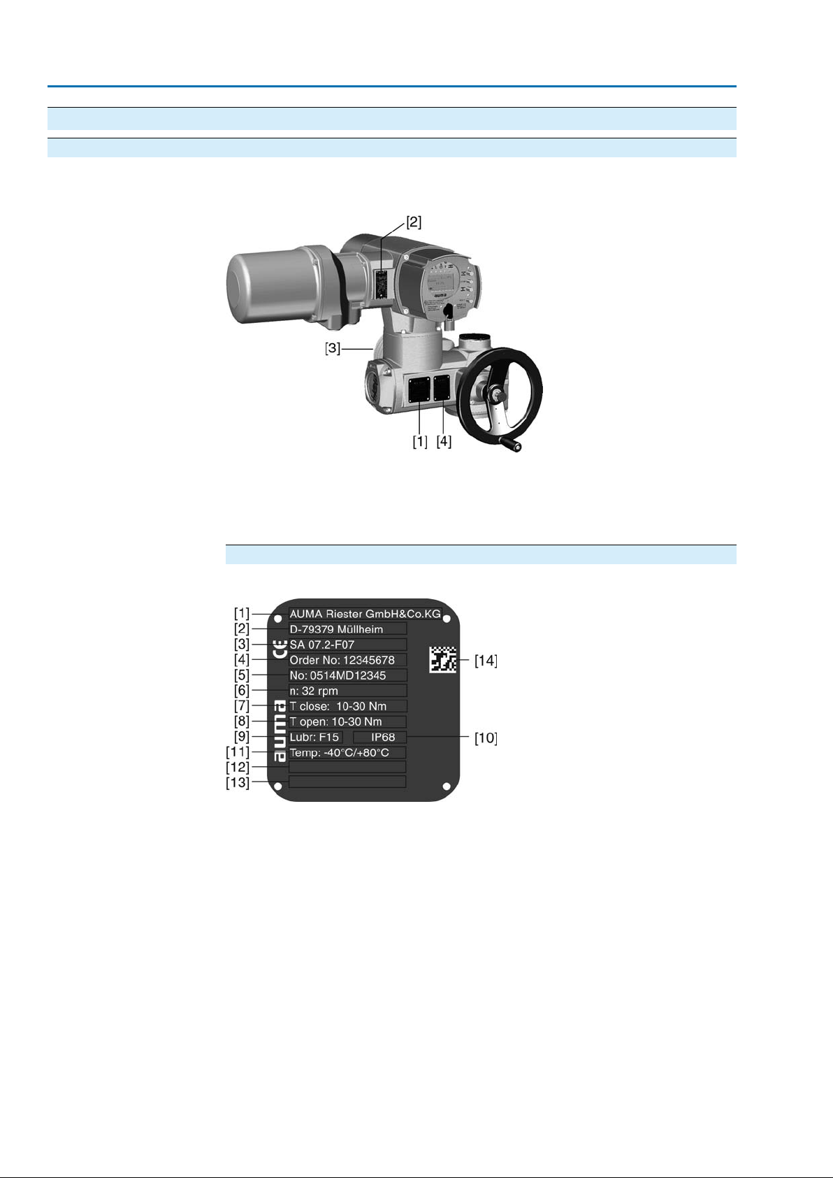
Each device component (actuator, controls, motor) is equipped with a name plate.
Figure 1: Arrangement of name plates
[1] Actuator name plate
[2] Actuator controls name plate
[3] Motor name plate
[4] Additional plate, e.g. KKS plate (Power Plant Classification System)
Actuator name plate
Figure 2: Actuator name plate (example)
[1] Name of manufacturer
[2] Address of manufacturer
[3] Type designation
[4] Order number
[5] Actuator serial number
[6] Speed
[7] Torque range in direction CLOSE
[8] Torque range in direction OPEN
[9] Type of lubricant
[10] Enclosure protection
[11] Permissible ambient temperature
[12] Can be assigned as an option upon customer request
[13] Can be assigned as an option upon customer request
[14] Data Matrix code
8
Page 9
SA 07.2 – SA 16.2 / SAR 07.2 – SAR 16.2 Control unit: electronic (MWG)
AC 01.2 Non-Intrusive Modbus TCP/IP Identification
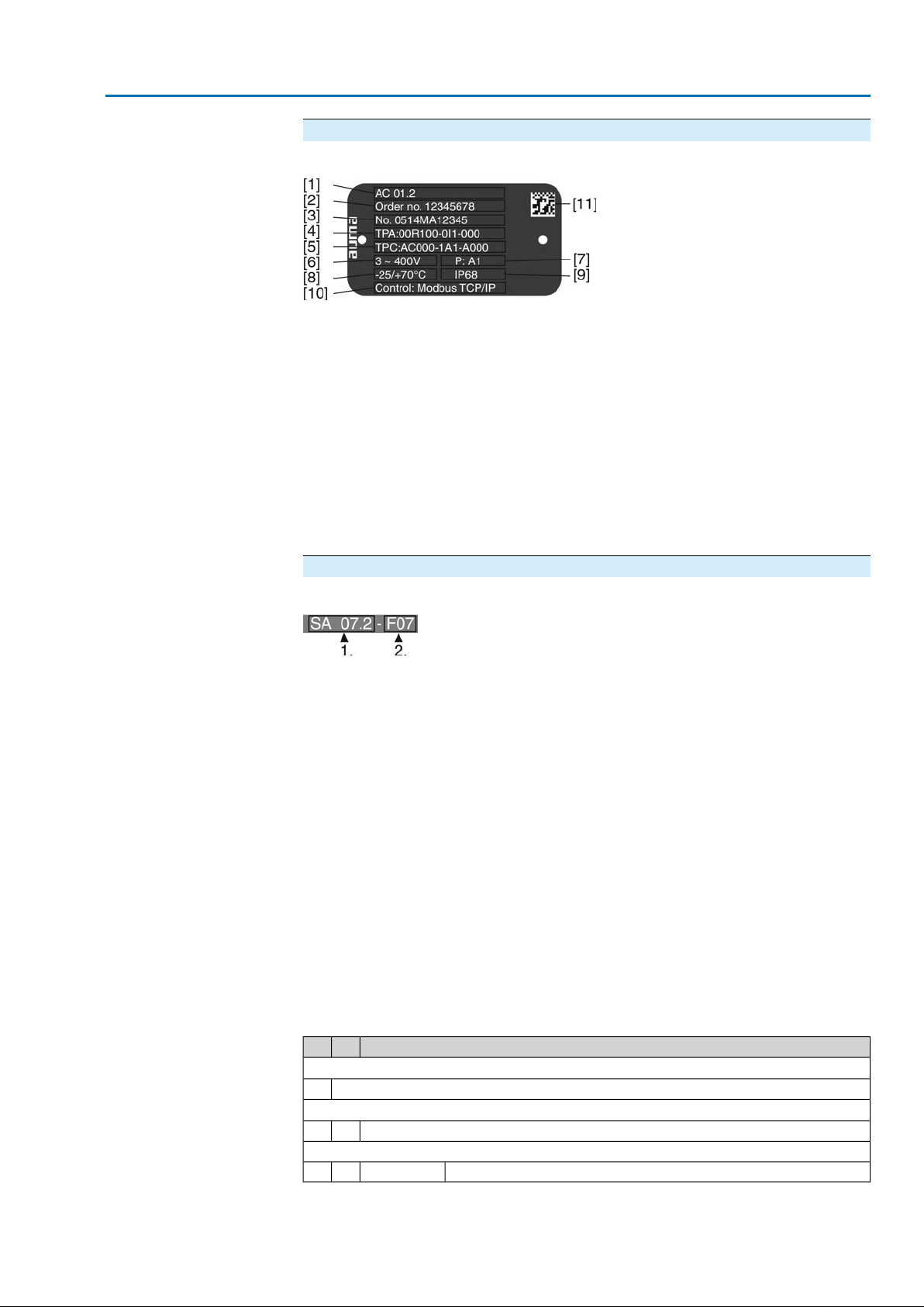
Actuator controls name plate
Figure 3: Controls name plate
[1] Type designation
[2] Order number
[3] Serial number
[4] Actuator terminal plan
[5] Actuator controls terminal plan
[6] Mains voltage
[7] AUMA power class for switchgear
[8] Permissible ambient temperature
[9] Enclosure protection
[10] Control
[11] Data Matrix code
Descriptions
Type designation Figure 4:Type designation (example)
1. Type and size of actuator
2. Flange size
Type and size
These instructions apply to the following devices types and sizes:
SA 07.2, 07.6, 10.2, 14.2, 14.6, 16.2 = multi-turn actuators for open-close duty
SAR 07.2, 07.6, 10.2, 14.2, 14.6, 16.2 = multi-turn actuators for modulating duty
AC 01.2 = AUMATIC actuator controls
Order number
The product can be identified using this number and the technical data as well as
order-related data pertaining to the device can be compiled.
Please always state this number for any product inquiries.
On the Internet at http://www.auma.com, we offer a service allowing authorised
users to download order-related documents such as wiring diagrams and technical
data (both in German and English), inspection certificates and the operation
instructions when entering the order number.
Serial number
Table 1: Description of serial number (with example)
Actuator terminal plan
MD123451405
1st+2nd position: Assembly in week
Week 0505
3rd+4th position:Year of production
Year of production: 201414
All other positions
Internal number for unambiguous product identificationMD12345
9. position after TPA: Position transmitter version
9
Page 10
SA 07.2 – SA 16.2 / SAR 07.2 – SAR 16.2 Control unit: electronic (MWG)
Identification AC 01.2 Non-Intrusive Modbus TCP/IP
I, Q = MWG (magnetic limit and torque transmitter)
AUMA power class for
switchgear
Data Matrix code
Control
2.2. Short description
The switchgear used in the actuator controls (reversing contactors/thyristors) are
classified according to AUMA power classes (e.g. A1, B1, ....).The power class
defines the max. permissible rated power (of the motor) the switchgear has been
designed for.The rated power (nominal power) of the actuator motor is indicated in
kW on the motor name plate. For the assignment of the A UMA pow er classes to the
nominal power of the motor types, refer to the separate electrical data sheets.
For switchgear without assignment to an y power classes, the actuator controls name
plate does not indicate the power class but the max. rated power in kW.
When registered as authorised user, you may use the AUMA Support App to scan
the Data Matrix code and directly access the order-related product documents without
having to enter order number of serial number.
Figure 5: Link to the App store:
Table 2: Control examples (indications on controls name plate)
DescriptionInput signal
Control via Modbus TCP/IP interfaceModbus TCP/IP
Multi-turn actuator
Actuator controls
Local con-
trols/AUMA CDT
Intrusive - Non-Intrusive
Definition in compliance with EN ISO 5210:
A multi-turn actuator is an actuator which transmits to the valve a torque for at least
one full revolution. It is capable of withstanding thrust.
AUMA multi-turn actuators are driven by an electric motor and are capable of
withstanding thrust in combination with output drive type A. For manual operation,
a handwheel is provided. Switching off in end positions may be either by limit or
torque seating. Controls are required to operate or process the actuator signals.
The AUMATIC actuator controls are used to operate AUMA actuators and are supplied
ready for use.The controls may be mounted directly to the actuator or separately
on a wall bracket.
When set to local control, it is possible to
●
operate the actuator via the local controls (push buttons and display) and perf orm
settings (contents of these instructions).
●
read in or out data or modify and save settings via the AUMA CDT software
(accessories), using a computer (laptop or PC).The connection between computer and AUMATIC is wireless via Bluetooth interface (not included in these
instructions).
●
Intrusive version (control unit: electromechanical):
Limit and torque setting is performed via switches in the actuator.
●
Non-Intrusive version (control unit: electronic):
Limit and torque setting is performed via the controls, actuator and controls
housings do not have to be opened. For this purpose, the actuator is equipped
with an MWG (magnetic limit and torque transmitter), also supplying analogue
torque feedback signals/torque indication and analogue position feedback signals/position indication.
10
Page 11
SA 07.2 – SA 16.2 / SAR 07.2 – SAR 16.2 Control unit: electronic (MWG)
AC 01.2 Non-Intrusive Modbus TCP/IP Transport, storage and packaging
3. Transport, storage and packaging
3.1. Transport
For transport to place of installation, use sturdy packaging.
Hovering load!
Risk of death or serious injury.
→
Do NOT stand below hovering load.
→
Attach ropes or hooks for the purpose of lifting by hoist only to housing and NOT
to handwheel.
→
Actuators mounted on valves: Attach ropes or hooks for the purpose of lifting
by hoist to valve and NOT to actuator.
→
Actuators mounted to gearboxes: Attach ropes or hooks f or the purpose of lifting
by hoist only to the gearbox using eyebolts and NOT to the actuator.
→
Actuators mounted to controls: Attach ropes or hooks for the purpose of lifting
by hoist only to the actuator and NOT to the controls.
3.2. Storage
Long-term storage
3.3. Packaging
Danger of corrosion due to inappropriate storage!
→
Store in a well-ventilated, dry room.
→
Protect against floor dampness by storage on a shelf or on a wooden pallet.
→
Cover to protect against dust and dirt.
→
Apply suitable corrosion protection agent to uncoated surfaces.
Damage on display caused by temperatures below permissible level!
→
The AUMATIC actuator controls must NOT be stored below –30 °C.
If the device must be stored for a long period (more than 6 months) the following
points must be observed in addition:
1. Prior to storage:
Protect uncoated surfaces, in particular the output drive parts and mounting
surface, with long-term corrosion protection agent.
2. At an interval of approx. 6 months:
Check for corrosion. If first signs of corrosion show , apply ne w corrosion protection.
Our products are protected by special packaging for transport when leaving the
factory .The packaging consists of en vironmentally friendly materials which can easily
be separated and recycled.We use the following packaging materials: wood,
cardboard, paper, and PE foil. For the disposal of the packaging material, we
recommend recycling and collection centres.
11
Page 12
SA 07.2 – SA 16.2 / SAR 07.2 – SAR 16.2 Control unit: electronic (MWG)
Assembly AC 01.2 Non-Intrusive Modbus TCP/IP
4. Assembly
4.1. Mounting position
AUMA actuators and actuator controls can be operated without restriction in any
mounting position.
4.2. Handwheel fitting
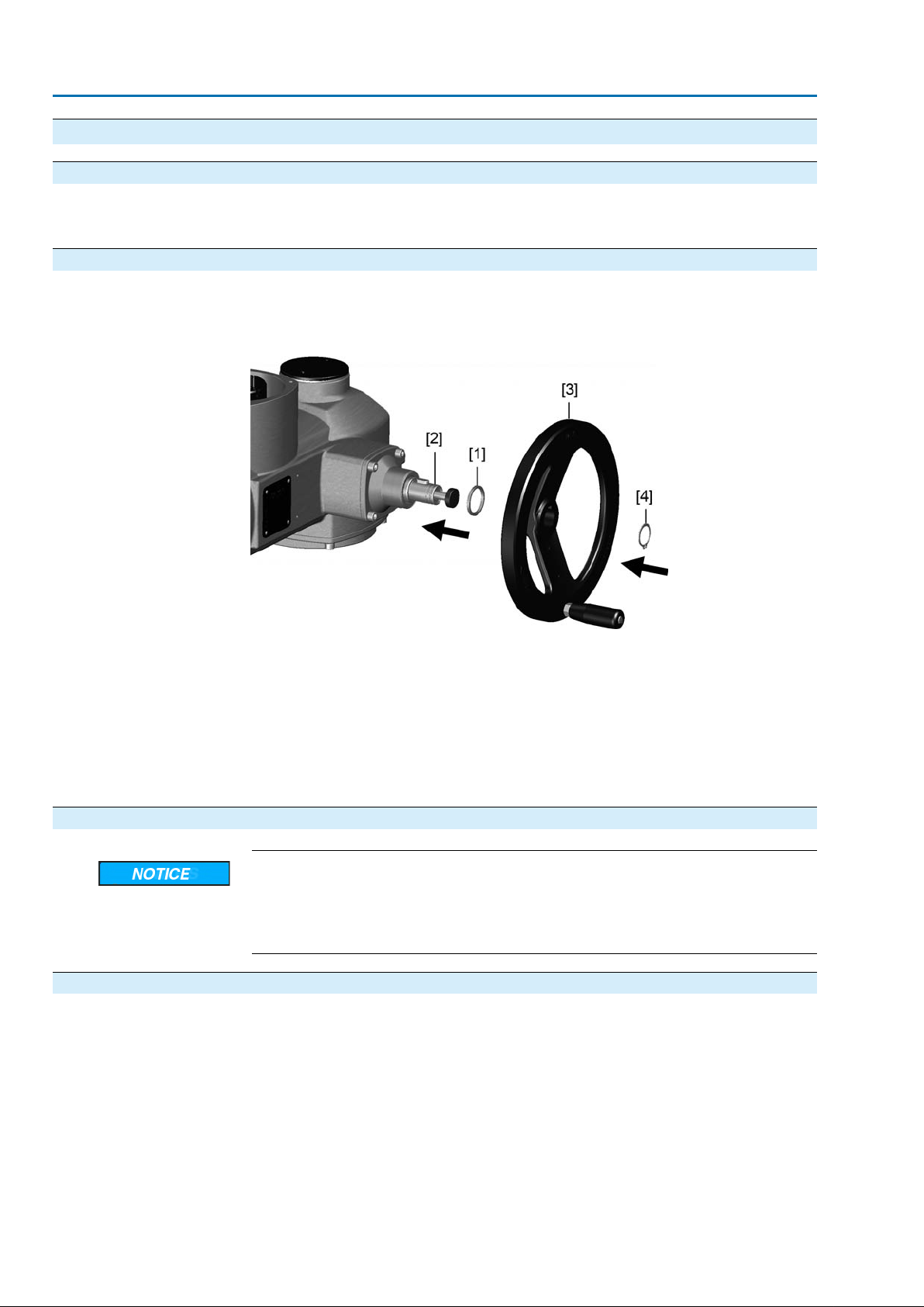
Information For transport purposes, handwheels from a diameter of 400 mm are supplied separ-
ately.
Figure 6: Handwheel
[1] Spacer
[2] Input shaft
[3] Handwheel
[4] Circlip
1. If required, fit spacer [1] onto input shaft [2].
2. Slip handwheel [3] onto input shaft.
3. Secure handwheel [3] using the circlip [4] supplied.
4.3. Multi-turn actuator: mount to valve/gearbox
Danger of corrosion due to damage to paint finish and condensation!
→
Touch up damage to paint finish after work on the device.
→
After mounting, connect the device immediately to electrical mains to ensure
that heater minimises condensation.
4.3.1. Output drive types B, B1 – B4 and E
●
Application
Design
For rotating, non-rising valve stem
●
Not capable of withstanding thrust
Output drive bore with keyway:
●
Types B1 – B4 with bore according to EN ISO 5210
●
Types B and E with bore according to DIN 3210
●
Later change from B1 to B3, B4, or E is possible.
12
Page 13
SA 07.2 – SA 16.2 / SAR 07.2 – SAR 16.2 Control unit: electronic (MWG)
AC 01.2 Non-Intrusive Modbus TCP/IP Assembly
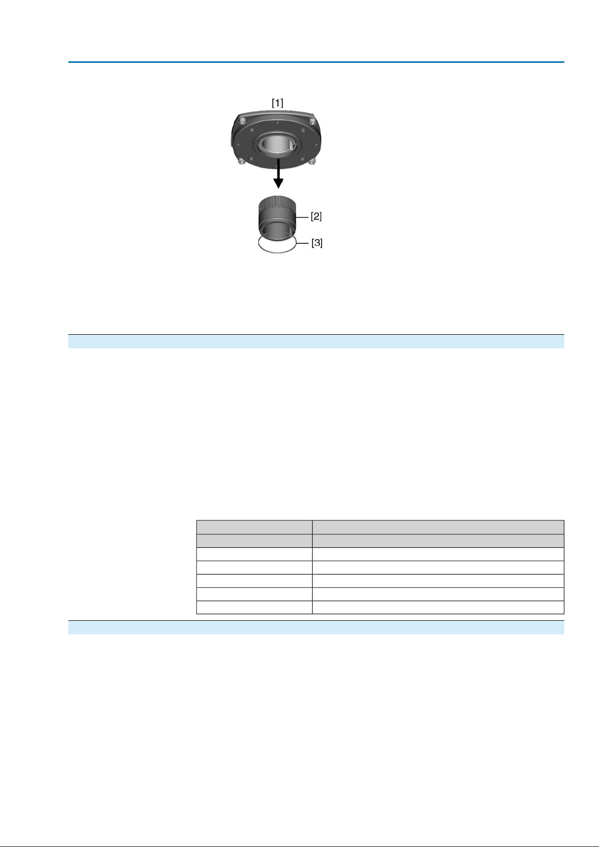
Figure 7: Output drive
[1] Output drive types B, B1 – B4, E and C
[2] Output drive sleeve/output drive plug sleve with bore and keyway
[3] Circlip
Information Spigot at flanges should be loose fit.
4.3.1.1. Multi-turn actuator (with output drive types B1 – B4 or E): mount to valve/gearbox
1. Check if mounting flanges fit together.
2. Check whether bore and keyway match the input shaft.
3. Apply a small quantity of grease to the input shaft.
4. Place multi-turn actuator.
Information: Ensure that the spigot fits uniformly in the recess and that the
mounting faces are in complete contact.
5. Fasten multi-turn actuator with screws according to table.
Information: We recommend applying liquid thread sealing material to the
screws to avoid contact corrosion.
6. Fasten screws crosswise to a torque according to table.
Table 3: Tightening torques for screws
Tightening torque TA [Nm]Screws
Strength class 8.8Threads
25M8
51M10
87M12
214M16
431M20
4.3.2. Output drive type A
●
Application
Output drive for rising, non-rotating valve stem
●
Capable of withstanding thrust
Information To adapt the actuators to output drive types A av ailab le on site with flanges F10 and
F14 (year of manufacture: 2009 and earlier), an adapter is required.The adapter
can be ordered from AUMA.
13
Page 14
SA 07.2 – SA 16.2 / SAR 07.2 – SAR 16.2 Control unit: electronic (MWG)
Assembly AC 01.2 Non-Intrusive Modbus TCP/IP
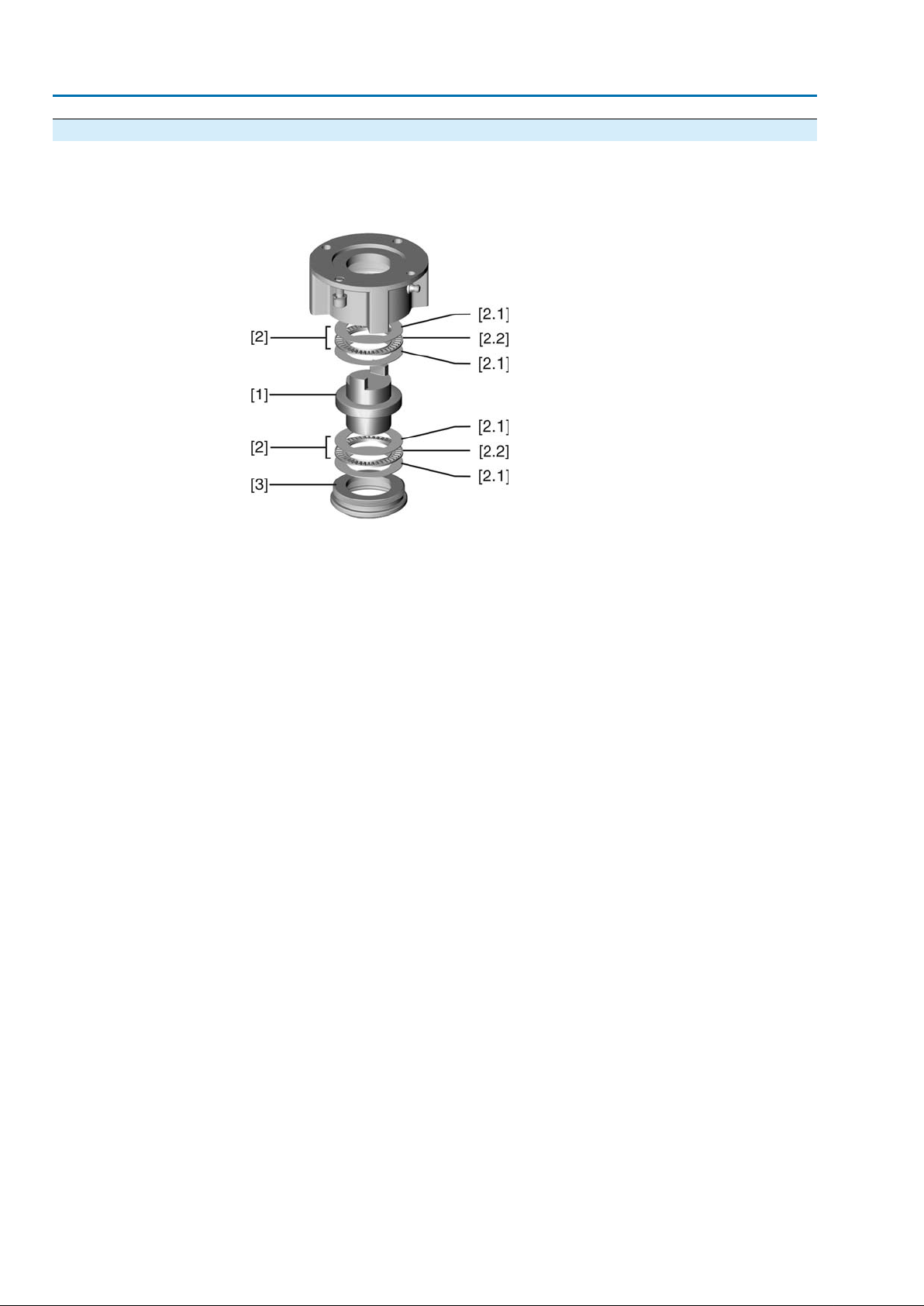
4.3.2.1. Stem nut: finish machining
This working step is only required if stem nut is supplied unbored or with pilot
✔
bore.
Figure 8: Design of output drive type A
[1] Stem nut
[2] Bearing
[2.1] Bearing race
[2.2] Bearing rim
[3] Spigot ring
1. Remove spigot ring [3] from output drive.
2. Remove stem nut [1] together with bearings [2].
3. Remove bearing races [2.1] and bearing rims [2.2] from stem nut [1].
4. Drill and bore stem nut [1] and cut thread.
Information: When fixing in the chuck, make sure stem nut runs true!
5. Clean the machined stem nut [1].
6. Apply sufficient Lithium soap EP multi-purpose grease to bearing rims [2.2] and
bearing races [2.1], ensuring that all hollow spaces are filled with grease.
7. Place greased bearing rims [2.2] and bearing races [2.1] onto stem nut [1].
8. Re-insert stem nut [1] with bearings [2] into output drive.
Information:Ensure that dogs or splines are placed correctly in the keyway of
the hollow shaft.
9. Screw in spigot ring [3] until it is firm against the shoulder.
14
Page 15
SA 07.2 – SA 16.2 / SAR 07.2 – SAR 16.2 Control unit: electronic (MWG)
AC 01.2 Non-Intrusive Modbus TCP/IP Assembly
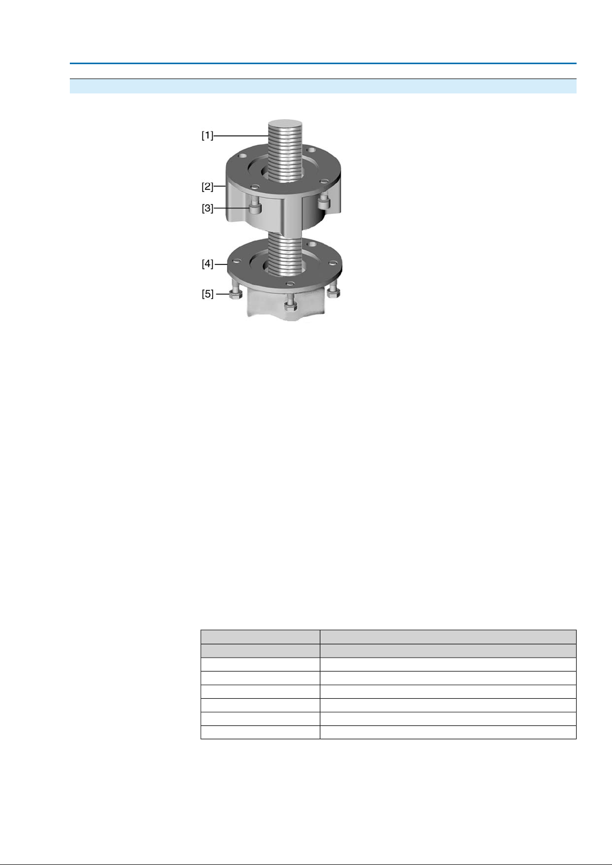
4.3.2.2. Multi-turn actuator (with output drive type A): mount to valve
Figure 9: Assembly with output drive type A
[1] Valve stem
[2] Output drive type A
[3] Screws to actuator
[4] Valve flange
[5] Screws to output drive
1. If the output drive type A is already mounted to the multi-turn actuator: Loosen
screws [3] and remove output drive type A [2].
2. Check if the flange of output drive type A matches the valve flange [4].
3. Apply a small quantity of grease to the valve stem [1].
4. Place output drive type A on valve stem and turn until it is flush on the valve
flange.
5. Turn output drive type A until alignment of the fixing holes.
6. Screw in fastening screws [5], however do not completely tighten.
7. Fit multi-turn actuator on the valve stem so that the stem nut dogs engage into
the output drive sleeve.
The flanges are flush with each other if properly engaged.
➥
8. Adjust multi-turn actuator until alignment of the fixing holes.
9. Fasten multi-turn actuator with screws [3].
10. Fasten screws [3] crosswise with a torque according to table.
Table 4: Tightening torques for screws
Tightening torque TA [Nm]Screws
Strength class 8.8Threads
11M6
25M8
51M10
87M12
214M16
431M20
11. Turn multi-turn actuator with handwheel in direction OPEN until valve flange
and output drive A are firmly placed together.
12. Tighten fastening screws [5] between valve and output drive type A crosswise
applying a torque according to table.
15
Page 16
SA 07.2 – SA 16.2 / SAR 07.2 – SAR 16.2 Control unit: electronic (MWG)
Assembly AC 01.2 Non-Intrusive Modbus TCP/IP
4.4. Accessories for assembly
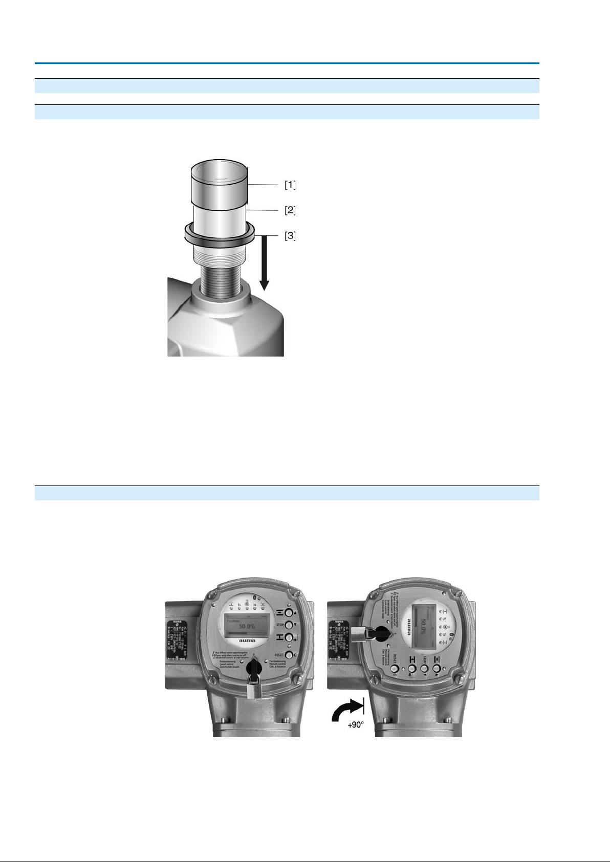
4.4.1. Stem protection tube for rising valve stem — Option —
Figure 10: Assembly of the stem protection tube
[1] Cap for stem protection tube
[2] Stem protection tube
[3] Sealing ring
1. Seal thread with hemp, Teflon tape, or thread sealing material.
2. Screw stem protection tube [2] into thread and tighten it firmly.
3. Push down the sealing ring [3] onto the housing.
4. Check whether cap for stem protection tube [1] is available and in perfect con-
dition.
4.5. Mounting positions of local controls
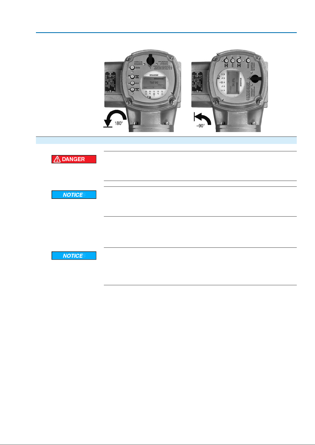
The mounting position of the local controls is selected according to the order. If , after
mounting the actuator to the valve or the gearbox on site, the local controls are in
an unfav ourable position, the mounting position can be changed at a later date . F our
mounting positions are possible.
Figure 11: Mounting positions A and B
16
Page 17
SA 07.2 – SA 16.2 / SAR 07.2 – SAR 16.2 Control unit: electronic (MWG)
AC 01.2 Non-Intrusive Modbus TCP/IP Assembly
Figure 12: Mounting positions C and D
4.5.1. Mounting positions: modify
Hazardous voltage!
Risk of electric shock.
→
Disconnect device from the mains before opening.
Electrostatic discharge ESD!
Risk of damage to electronic components.
→
Earth both operators and devices.
1. Loosen screws and remove the local controls.
2. Check whether O-ring is in good condition, correctly insert O-ring.
3. Turn local controls into new position and re-place.
Cable damage due to twisting or pinching!
Risk of functional failures.
→
Turn local controls by a maximum of 180°.
→
Carefully assemble local controls to avoid pinching the cables.
4. Fasten screws evenly crosswise.
17
Page 18
SA 07.2 – SA 16.2 / SAR 07.2 – SAR 16.2 Control unit: electronic (MWG)
Electrical connection AC 01.2 Non-Intrusive Modbus TCP/IP
5. Electrical connection
5.1. Basic information
Danger due to incorrect electrical connection
Failure to observe this warning can result in death, serious injury , or property damage.
→
The electrical connection must be carried out exclusively by suitably qualified
personnel.
→
Prior to connection, observe basic information contained in this chapter.
→
After connection but prior to applying the voltage, observe the <Commissioning>
and <Test run> chapters.
Wiring diagram/terminal
plan
Permissible networks
(supply networks)
Protection on site
The pertaining wiring diagram/terminal plan (both in German and English) is attached
to the device in a weather-proof bag, together with these operation instructions. It
can also be requested from AUMA (state order number, refer to name plate) or
downloaded directly from the Internet (http://www.auma.com).
The controls (actuators) are suitable for for use in TN and TT networks with directly
earthed star point and a maximum voltage of 690 V AC. Use in IT networks is
permitted while observing the respective <Protection on site> for for maiximum supply
voltages of 600 V AC.
For short-circuit protection and for disconnecting the actuator from the mains, fuses
and disconnect switches have to be provided by the customer.
The current values for respective sizing is derived from the current consumption of
the motor (refer to electrical data sheet) plus the current consumption of the controls.
Table 5: Current consumption controls
Max. current consumptionMains voltage
–30 %±10 %Permissible variation of the mains voltage
1,200 mA750 mA100 to 120 V AC
750 mA400 mA208 to 240 V AC
400 mA250 mA380 to 500 V AC
400 mA200 mA515 to 690 V AC
Power supply for the
controls (electronics)
Safety standards
18
Table 6: Maximum permissible protection
Max. protectionRated powerSwitchgear
16 A (gL/gG)up to 1.5 kWReversing contactor A1
32 A (gL/gG)up to 7.5 kWReversing contactor A2
63 A (gL/gG)up to 11 kWReversing contactor A3
16 A (g/R) I²t<1,500A²sup to 1.5 kWThyristor B1
32 A (g/R) I²t<1,500A²sup to 3 kWThyristor B2
63 A (g/R) I²t<5,000A²sup to 5.5 kWThyristor B3
If controls are mounted separately from actuator (controls on wall brack et): Consider
length and cross section of connecting cable when defining the protection required.
Use appropriate insulation monitors when working in power installations, for e xample
an insulation monitor measuring the pulse code.
In case of external supply of the controls (electronics):The external power supply
must have a reinforced insulation against the mains voltage in accordance with IEC
61010-1 and may only be supplied by a circuit limited to 150 VA in accordance with
IEC 61010-1.
All externally connected devices shall comply with the relevant safety standards.
Page 19
SA 07.2 – SA 16.2 / SAR 07.2 – SAR 16.2 Control unit: electronic (MWG)
AC 01.2 Non-Intrusive Modbus TCP/IP Electrical connection
Cable installation in ac-
cordance with EMC
Type of current, mains
voltage and mains fre-
quency
Signal and bus cables are susceptible to interference.
Motor cables are interference sources.
●
Lay cables being susceptible to interference or sources of interference at the
highest possible distance from each other.
●
The interference immunity of signal and bus cables increases if the cables are
laid close to the earth potential.
●
If possible, avoid laying long cables and make sure that they are installed in
areas being subject to low interference.
●
Avoid long par allel paths with cab les being either susceptible to interf erence or
interference sources.
●
For the connection of remote position transmitters, screened cables must be
used.
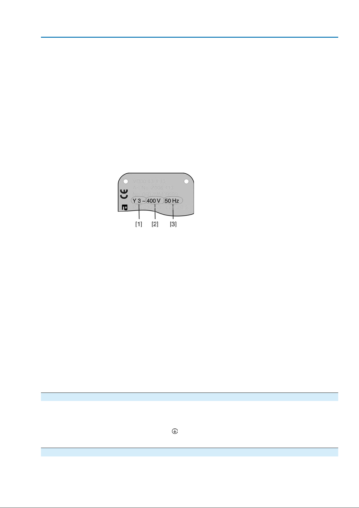
Type of current, mains voltage and mains frequency must match the data on the
motor name plate.
Figure 13: Motor name plate (example)
[1] Type of current
[2] Mains voltage
[3] Mains frequency (for 3-ph and 1-ph AC motors)
●
Connecting cables
For device insulation, appropriate (v oltage-proof) cables must be used. Specify
cables for the highest occurring rated voltage.
●
Use connecting cable with appropriate minimum rated temperature.
●
For connecting cables exposed to UV radiation (outdoor installation), use UV
resistant cables.
Bus cables
Only use cables for Modbus TCP/IP connection complying with category 5 (Cat. 5)
or category 6 (Cat. 6).
Recommendation: Use of Cat. 6A Ethernet cables (RJ45 connector supplied within
the electrical connection for field assembly is suitable for Cat. 6A cables).
Prior to installation, please note:
●
Maximum cable length: 100 m.
●
Install data cables at a distance of minimum 20 cm to other cables.
●
If possible, data cables should be laid in a separate, conductive, and earthed
cable tray.
●
Make sure to avoid potential differences between the individual devices on the
bus (perform an equipotential earth bonding).
5.2. Connection with AUMA plug/socket connector Cross sections AUMA plug/socket connector:
●
Power terminals (U1, V1, W1, U2, V2, W2): max. 6 mm² flexible/10 mm² solid
●
PE connection : max. 6 mm² flexible/10 mm² solid
●
Control contacts (1 to 50): max. 2.5 mm²
5.2.1. Terminal compartment: open
Information The bus connection can be separately accessed from the mains connection (refer
to <Bus terminal compartment: open>.
19
Page 20
SA 07.2 – SA 16.2 / SAR 07.2 – SAR 16.2 Control unit: electronic (MWG)
Electrical connection AC 01.2 Non-Intrusive Modbus TCP/IP
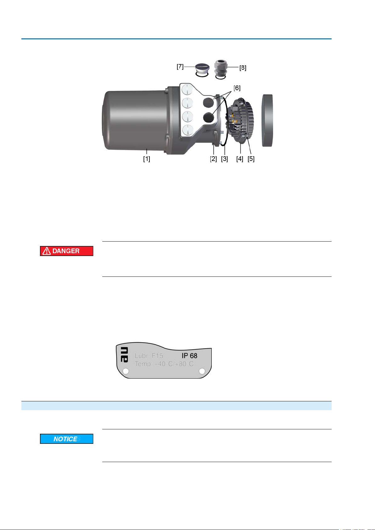
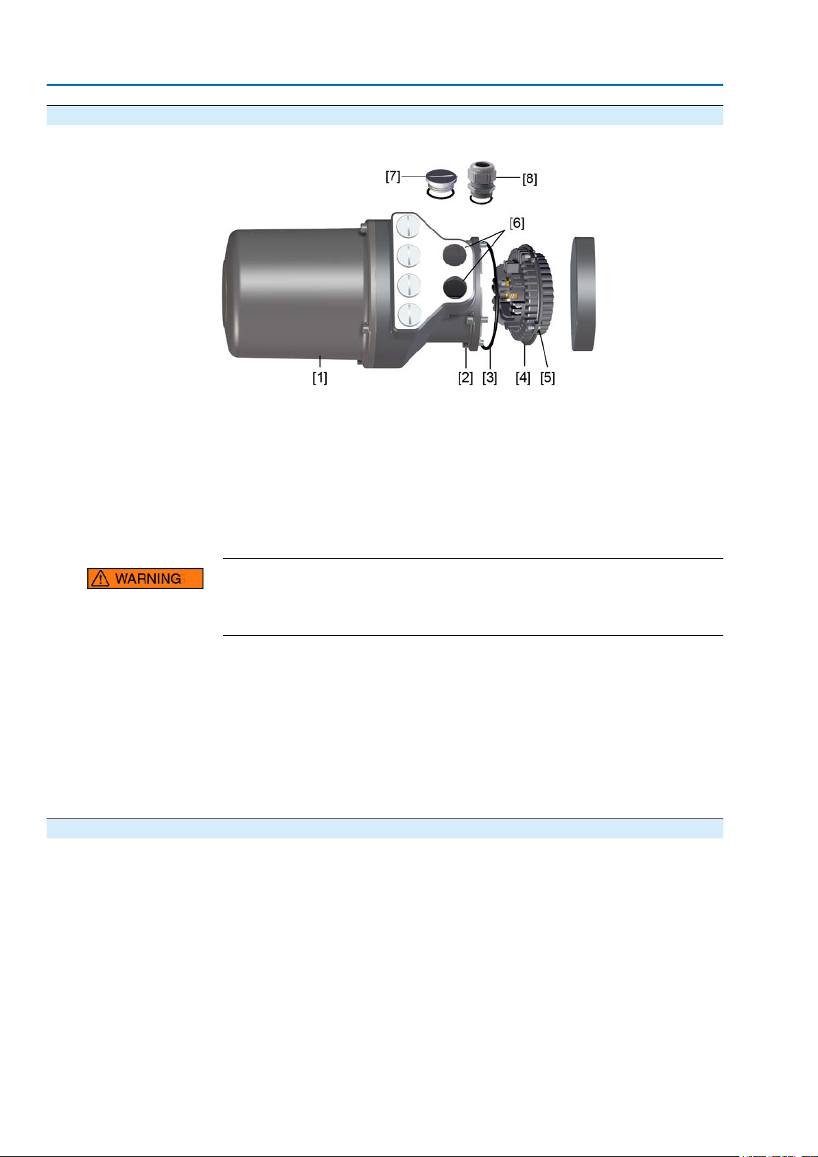
Figure 14: Mains connection AUMA plug/socket connector SFH
[1] Connection housing
[2] Screws for frame
[3] O-ring
[4] Screws for socket carrier
[5] Socket carrier
[6] Cable entry for mains
[7] Blanking plugs
[8] Cable gland (not included in delivery)
5.2.2. Cable connection
Hazardous voltage!
Risk of electric shock.
→
Disconnect device from the mains before opening.
1. Loosen screws [2] and remove connection housing [1].
2. Loosen screws [4] and remove socket carrier [5] from connection housing [1].
3. Insert cable glands [8] suitable for connecting cables.
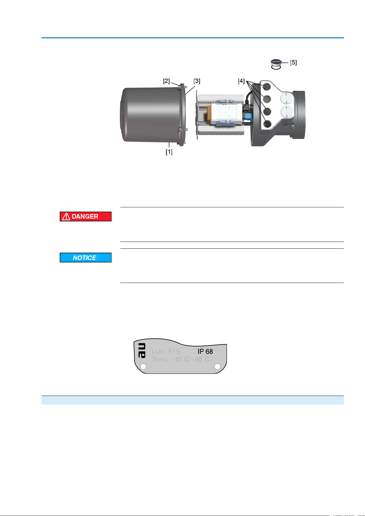
The enclosure protection IP… stated on the name plate is only ensured if suit-
➥
able cable glands are used.
Figure 15: Example: Name plate for enclosure protection IP68
4. Seal unused cable entries [6] with suitable blanking plugs [7].
5. Insert the cables into the cable glands [8].
✔ Observe permissible cross sections.
Danger of corrosion: Damage due to condensation!
→
After mounting, commission the device immediately to ensure that heater minimises condensation.
1. Remove cable sheathing.
2. Strip wires.
3. For flexible cables: Use end sleeves according to DIN 46228.
20
Page 21
SA 07.2 – SA 16.2 / SAR 07.2 – SAR 16.2 Control unit: electronic (MWG)
AC 01.2 Non-Intrusive Modbus TCP/IP Electrical connection
4. Connect cables according to order-related wiring diagram.
In case of a fault: Hazardous voltage while protective earth conductor is NOT
connected!
Risk of electric shock.
→
Connect all protective earth conductors.
→
Connect PE connection to external protective earth conductor of connecting
cables.
→
Start running the device only after having connected the protective earth conductor.
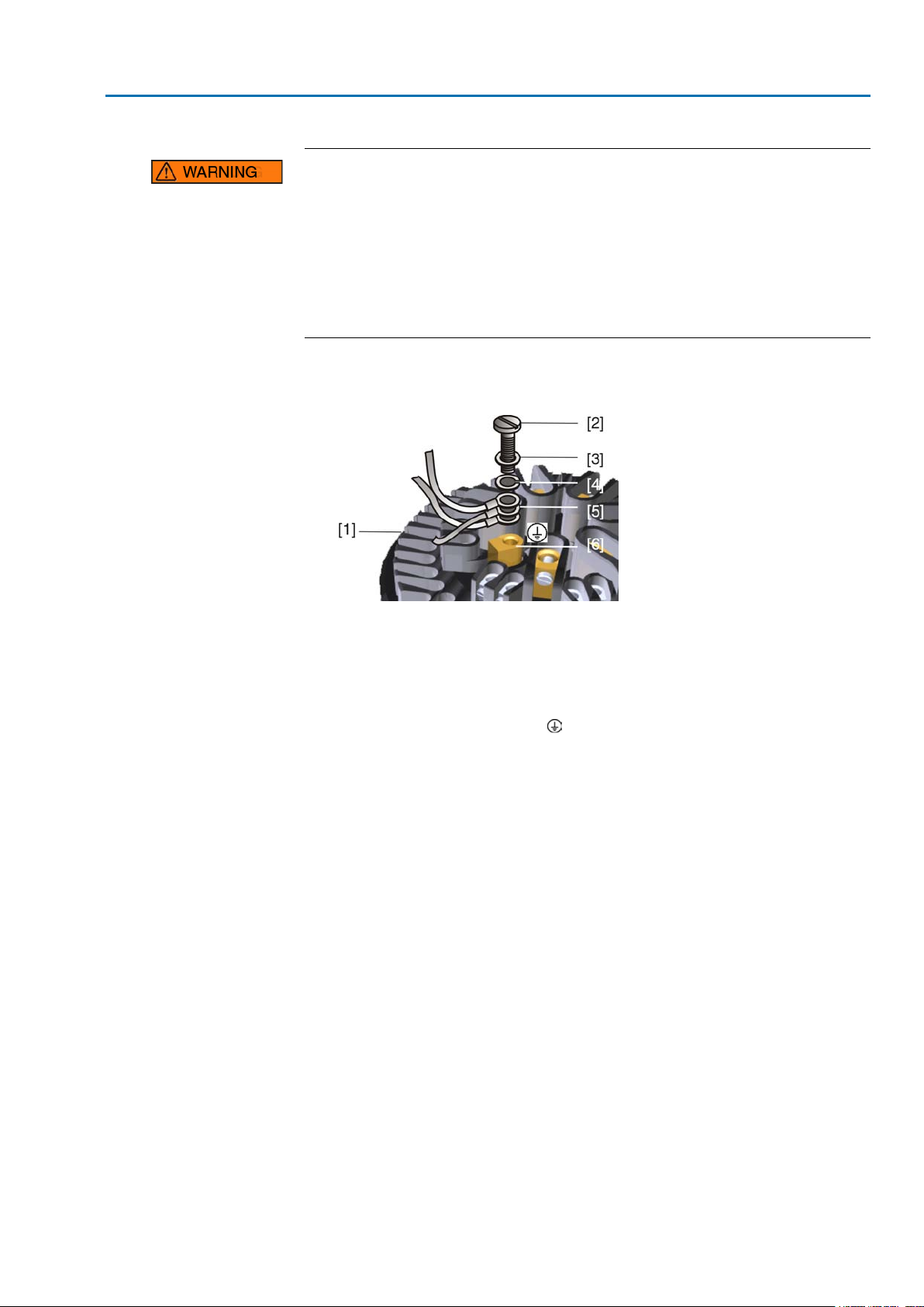
5. Tighten PE conductors firmly to PE connection using ring lugs (flexib le cab les)
or loops (rigid cables).
Figure 16: PE connection
[1] Socket carrier
[2] Screw
[3] Washer
[4] Lock washer
[5] Protective earth with ring lugs/loops
[6]
PE connection, symbol:
Information Some actuators are equipped with an additional motor heater.The motor heater
minimises condensation within the motor.
21
Page 22
SA 07.2 – SA 16.2 / SAR 07.2 – SAR 16.2 Control unit: electronic (MWG)
Electrical connection AC 01.2 Non-Intrusive Modbus TCP/IP
5.2.3. Terminal compartment: close
Figure 17: AUMA plug/socket connector SFH
[1] Connection housing
[2] Screws for frame
[3] O-ring
[4] Screws for socket carrier
[5] Socket carrier
[6] Cable entry for mains
[7] Blanking plugs
[8] Cable gland (not included in delivery)
Short-circuit due to pinching of cables!
Risk of electric shock and functional failures.
→
Carefully fit socket carrier to avoid pinching the cables.
1. Insert the socket carrier [5] into the connection housing [1] and fasten with
screws [4].
2. Clean sealing faces of connection housing [1] and housing.
3. Check whether O-ring [3] is in good condition, replace if damaged.
4. Apply a thin film of non-acidic grease (e.g. petroleum jelly) to the O-ring and
insert it correctly.
5. Fit connection housing [1] and fasten screws [2] evenly crosswise.
6. Fasten cable glands [8] applying the specified torque to ensure the required
enclosure protection.
5.2.4. Bus terminal compartment: open
For connecting Industrial Ethernet cables, the AUMA plug/socket connector is used
as field-assembly Ethernet connector.When removing the cover [1], the connection
board is easily accessible.
22
Page 23
SA 07.2 – SA 16.2 / SAR 07.2 – SAR 16.2 Control unit: electronic (MWG)
AC 01.2 Non-Intrusive Modbus TCP/IP Electrical connection
Figure 18: AUMA plug/socket connector SFH
[1] Cover (bus terminal compartment)
[2] Screws for cover
[3] O-ring
[4] Cable entries for bus cables
[5] Blanking plug
Hazardous voltage!
Risk of electric shock.
→
Disconnect device from the mains before opening.
Electrostatic discharge ESD!
Risk of damage to electronic components.
→
Earth both operators and devices.
1. Loosen screws [2] and remove cover [1].
2. Insert cable glands suitable for fieldbus cables.
The enclosure protection IP… stated on the name plate is only ensured if suit-
➥
able cable glands are used.
Example: Name plate shows enclosure protection IP68.
➥
3. Seal unused cable entries [4] with suitable blanking plugs [5].
4. Insert the wires into the cable glands.
5.2.5. Industrial Ethernet cable: connect
Information This description applies to the connection via CAT 6A Ethernet cables.
23
Page 24
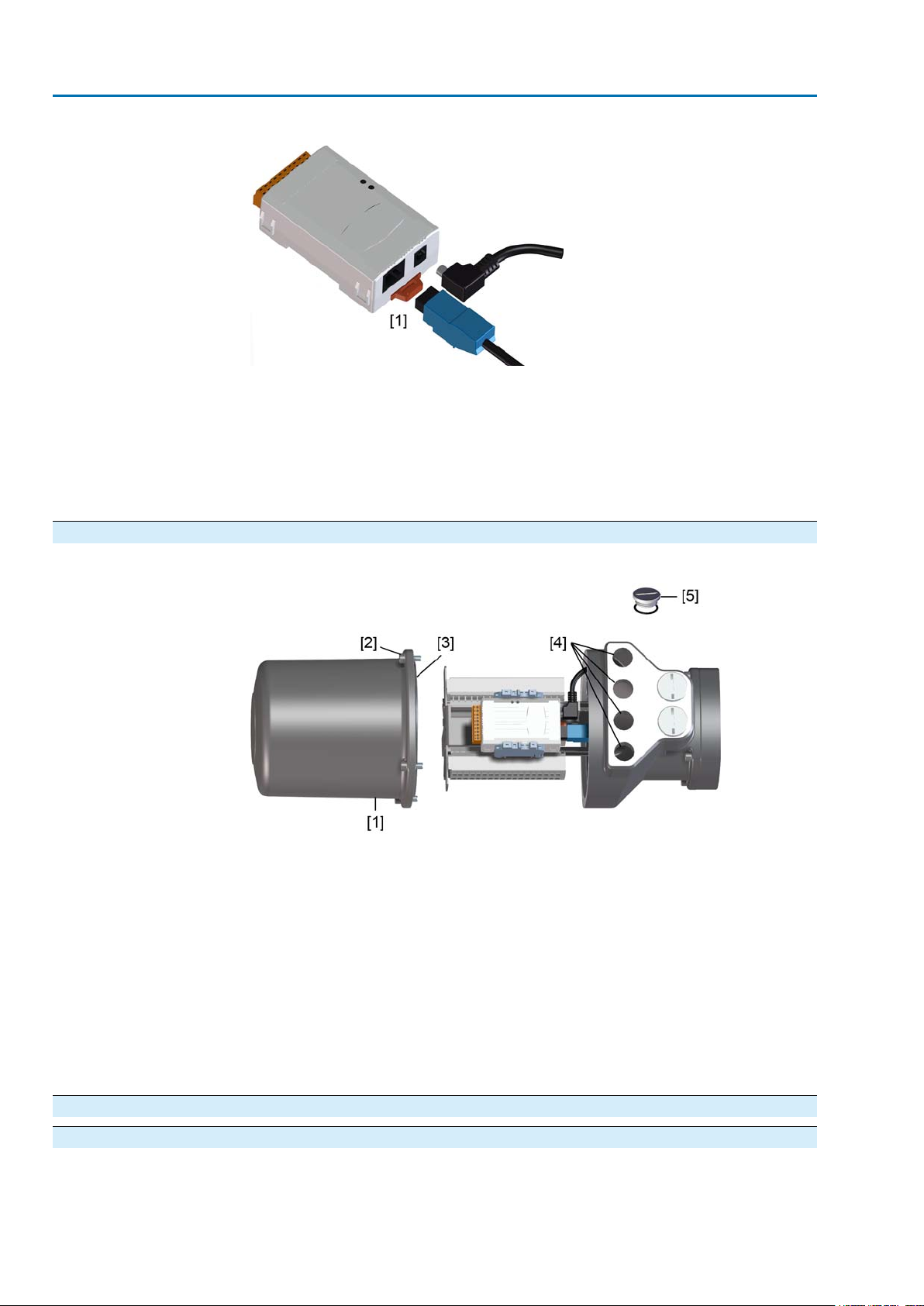
SA 07.2 – SA 16.2 / SAR 07.2 – SAR 16.2 Control unit: electronic (MWG)
Electrical connection AC 01.2 Non-Intrusive Modbus TCP/IP
Figure 19: Modbus TCP-RTU Gateway
[1] RJ45 plug-in socket for connecting the Industrial Ethernet cable
Cable connection
1. For connecting cables to RJ45 connectors, proceed in compliance with the
connector manufacturer specifications.
When using the RJ45 connector supplied by A UMA, please heed the assembly
➥
instructions provided.
2. Connect RJ45 connector to port for Ethernet cable [1].
5.2.6. Bus terminal compartment: close
Figure 20: AUMA plug/socket connector SFH
[1] Cover (fieldbus connection compartment)
[2] Screws for cover
[3] O-ring
[4] Cable entries for bus cables
[5] Blanking plug
1. Clean sealing faces of cover [1] and housing.
2. Apply a thin film of non-acidic grease (e.g. petroleum jelly) to the sealing f aces.
3. Check whether O-ring [3] is in good condition, correctly insert O-ring.
4. Fit cover [1] and fasten screws [2] evenly crosswise.
5. Fasten cable glands with the specified torque to ensure the required enclosure
protection.
5.3. Accessories for electrical connection
5.3.1. Controls mounted on wall bracket — Option —
The wall bracket allows separate mounting of controls and actuator.
●
Application
24
If the actuator cannot be accessed.
Page 25
SA 07.2 – SA 16.2 / SAR 07.2 – SAR 16.2 Control unit: electronic (MWG)
AC 01.2 Non-Intrusive Modbus TCP/IP Electrical connection
●
If the actuator is subjected to high temperatures.
●
In case of heavy vibration of the valve.
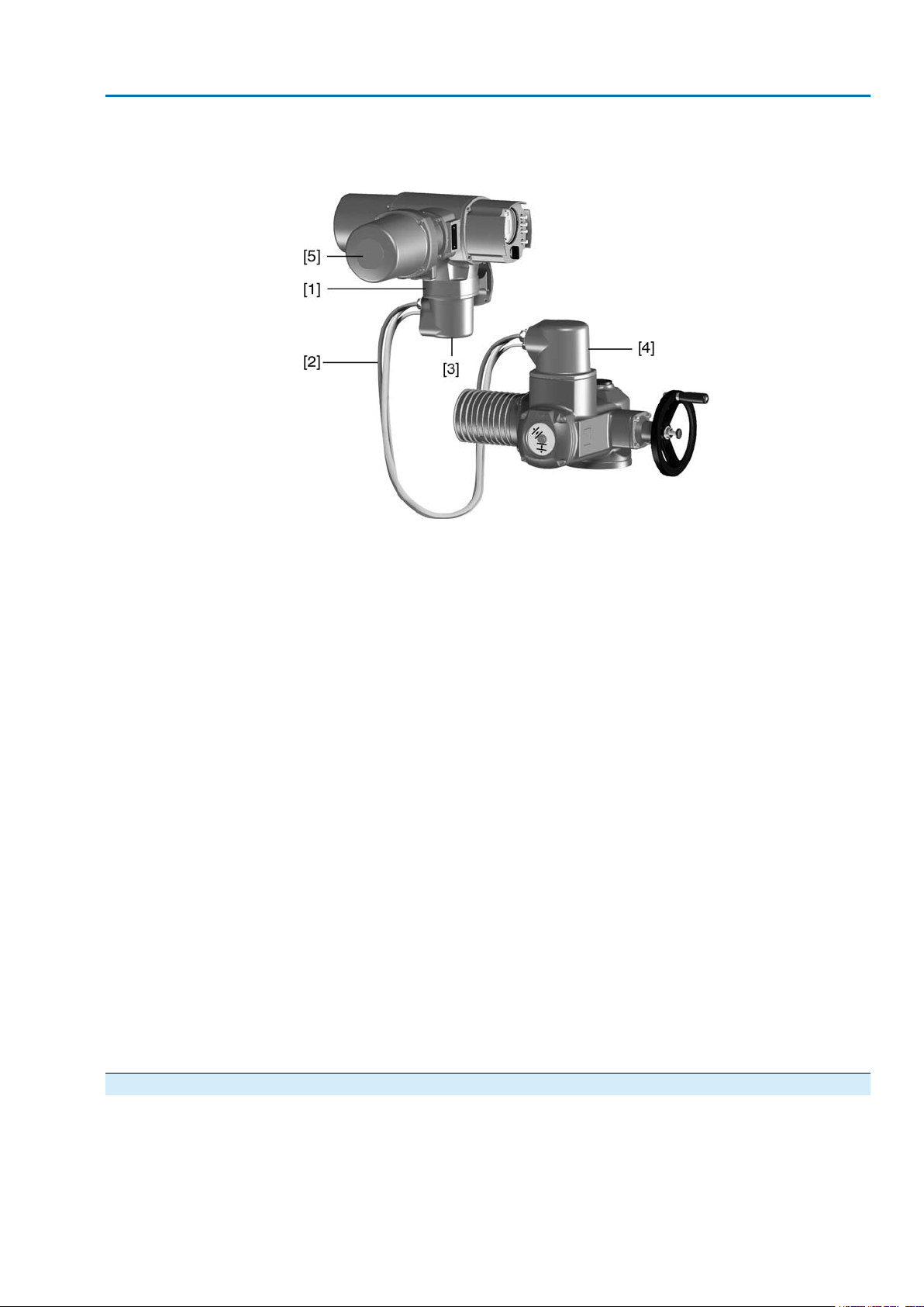
Design Figure 21: Design principle with wall bracket
Observe prior to connec-
tion
[1] Wall bracket
[2] Connecting cables
[3] Electrical connection of wall bracket (XM)
[4] Electrical connection of actuator (XA)
[5] Electrical connection/bus connection of controls (XK) - customer plug
●
Permissible length of connecting cables: max. 100 m.
●
We recommend: AUMA cable set LSW20.
●
If the AUMA cable set is not used:
- Use suitable flexible and screened connecting cables.
- Use separate, CAN bus data cable f or MWG of 120 Ohm character impedance (e.g. UNITRONIC BUS-FD P CAN UL/CSA - 2 x 2 x 0.5 mm², manufacturer: Lapp).
- Data cable connection: XM2-XA2 = CAN L, XM3-XA3 = CAN H.
- Voltage supply MWG: XM6-XA6 = GND, XM7-XA7 = + 24 V DC (refer to
wiring diagram).
- For the electrical connection at wall bracket [3], the terminals are made
as crimp connections.
- Use a suitable four indent crimp tool for crimping.
- Cross sections for flexible wires:
- Control cables: max. 0.75 to 1.5 mm²
- Mains connection: max. 2.5 to 4 mm²
●
When using connecting cables, e.g. of the heater, requiring direct wiring from
the actuator to the XK customer connector (XA-XM-XK, refer to wiring diagram),
these connecting cables must be subject to an insulation test in compliance
with EN 50178. Connecting cables for MWG do not belong to this group.They
may not be subject to an insulation test.
5.3.2. Parking frame
Application
— Option —
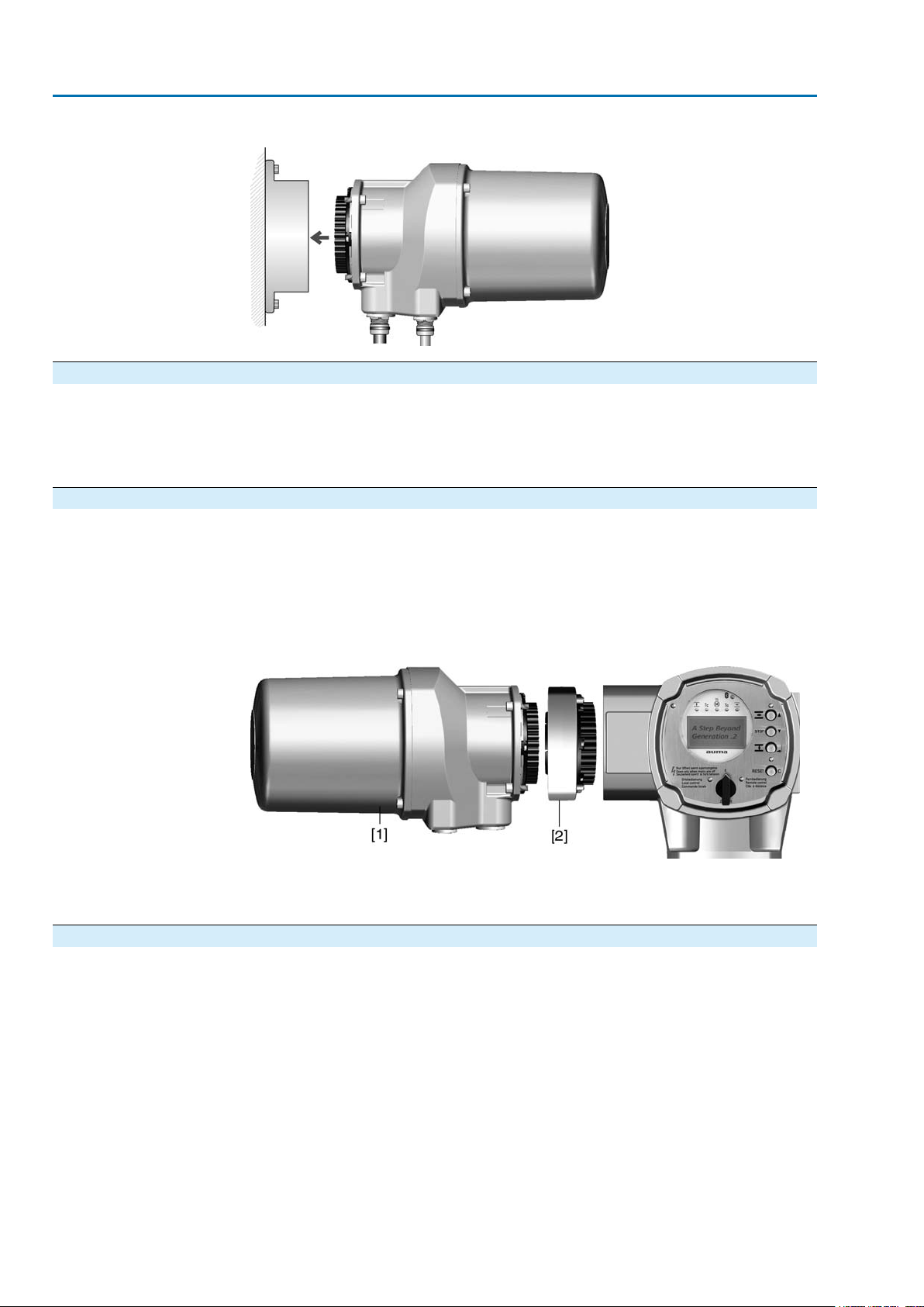
Parking frame for safe storage of a disconnected plug.
For protection against touching the bare contacts and against environmental
influences.
25
Page 26
SA 07.2 – SA 16.2 / SAR 07.2 – SAR 16.2 Control unit: electronic (MWG)
Electrical connection AC 01.2 Non-Intrusive Modbus TCP/IP
Figure 22: Parking frame
5.3.3. Protection cover — Option —
Application
Protection cover for plug compartment when plug is removed.
The open terminal compartment can be closed using a protective cover (not
illustrated).
5.3.4. Double sealed intermediate frame
— Option —
Application
When removing the electrical connection or due to leaky cable glands, ingress of
dust and water into the housing is possible.This is prevented eff ectiv ely b y inserting
the double sealed intermediate frame [2] between the plug/socket connector [1] and
the housing of the device.The enclosure protection of the device (IP68) will not be
affected, even if the electrical connection [1] is removed.
Figure 23: Electrical connection with double sealed intermediate frame
[1] Electrical connection [2] Double sealed intermediate frame
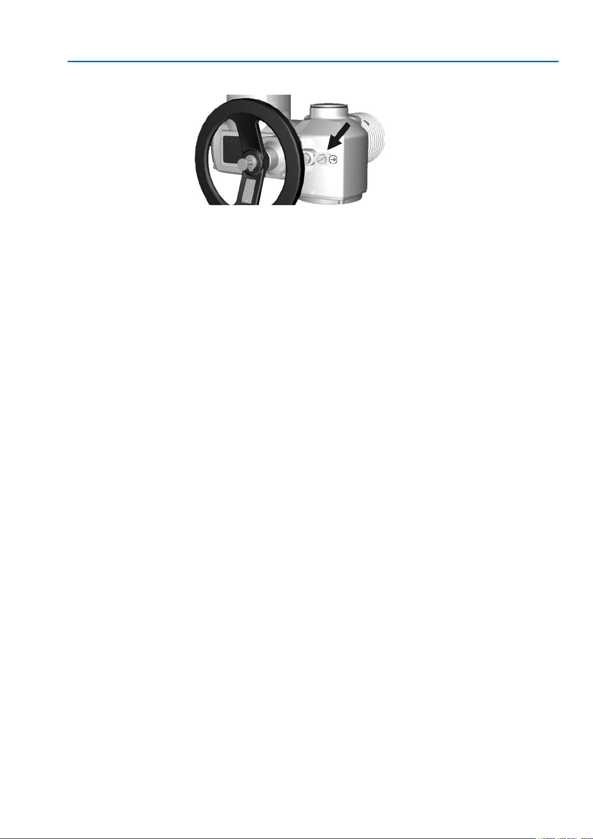
5.3.5. External earth connection — Option —
Application
External earth connection (terminal clamp) for connection to equipotential
compensation.
26
Page 27
SA 07.2 – SA 16.2 / SAR 07.2 – SAR 16.2 Control unit: electronic (MWG)
AC 01.2 Non-Intrusive Modbus TCP/IP Electrical connection
Figure 24: Earth connection
Cross sections of earth connection:
●
2 x 2.5 mm² to 6 mm² (solid and stranded conductors) or
●
2 x 1.5 mm² to 4 mm² (fine stranded conductors)
27
Page 28
SA 07.2 – SA 16.2 / SAR 07.2 – SAR 16.2 Control unit: electronic (MWG)
Operation AC 01.2 Non-Intrusive Modbus TCP/IP
6. Operation
Valve damage due to incorrect basic setting!
→
Prior to electrical operation of the actuator, the basic settings i.e. type of seating,
torque and limit switching have to be completed.
6.1. Manual operation
For purposes of setting and commissioning, in case of motor failure or power f ailure,
the actuator may be operated manually. Manual operation is engaged by an internal
change-over mechanism.
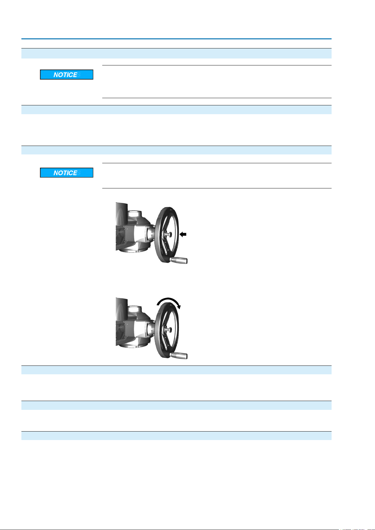
6.1.1. Manual operation: engage
Damage at the motor coupling due to faulty operation!
→
Engage manual operation only during motor standstill.
1. Press push button.
2. Turn handwheel in desired direction.
→
To close the valve, turn handwheel clockwise:
Drive shaft (valve) turns clockwise in direction CLOSE.
➥
6.1.2. Manual operation: disengage
Manual operation is automatically disengaged when motor is started again.The
handwheel does not rotate during motor operation.
6.2. Motor operation
Perform all commissioning settings and the test run prior to motor operation.
✔
6.2.1. Local actuator operation
Local actuator operation is performed using the push buttons of the local controls of
the AC.
28
Page 29
SA 07.2 – SA 16.2 / SAR 07.2 – SAR 16.2 Control unit: electronic (MWG)
AC 01.2 Non-Intrusive Modbus TCP/IP Operation
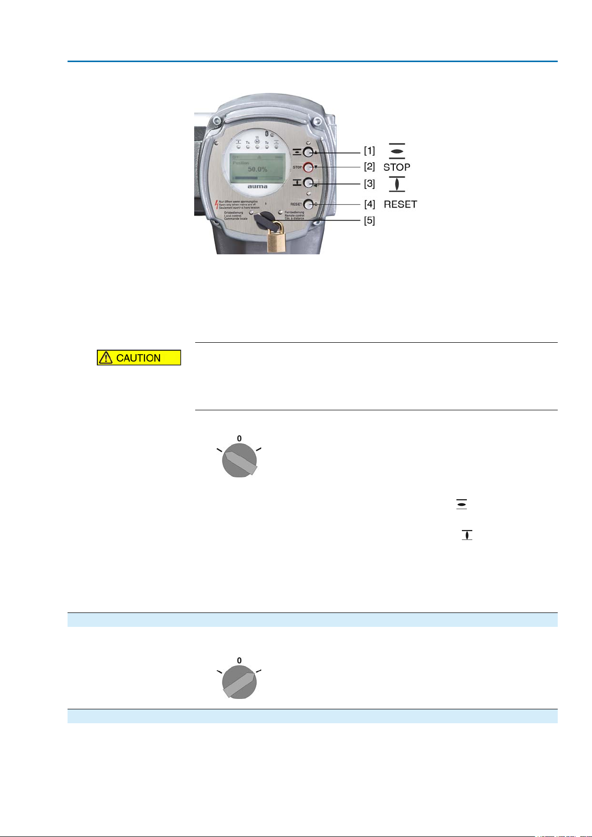
Figure 25: Local controls
[1] Push button for operation command in direction OPEN
[2] Push button STOP
[3] Push button for operation command in direction CLOSE
[4] Push button RESET
[5] Selector switch
Hot surfaces, e.g. possibly caused by high ambient temperatures or strong
direct sunlight!
Danger of burns
→
Check surface temperature and wear protective gloves, if required.
→
Set selector switch [5] to position Local control (LOCAL).
The actuator can now be operated using the push buttons [1 – 3].
➥
-
Run actuator in direction OPEN: Press push button [1] .
- Stop actuator: Press push button STOP [2].
-
Run actuator in direction CLOSE: Press push button [3] .
Information OPEN - CLOSE operation commands can be given either in push-to-run or in self-
retaining operation mode. In self-retaining mode, the actuator runs to the defined
end position after pressing the button, unless another command has been received
beforehand. For further information, please refer to Manual (Operation and setting).
6.2.2. Actuator operation from remote
→
Set selector switch to position Remote control (REMOTE).
6.3. Menu navigation via push buttons (for settings and indications)
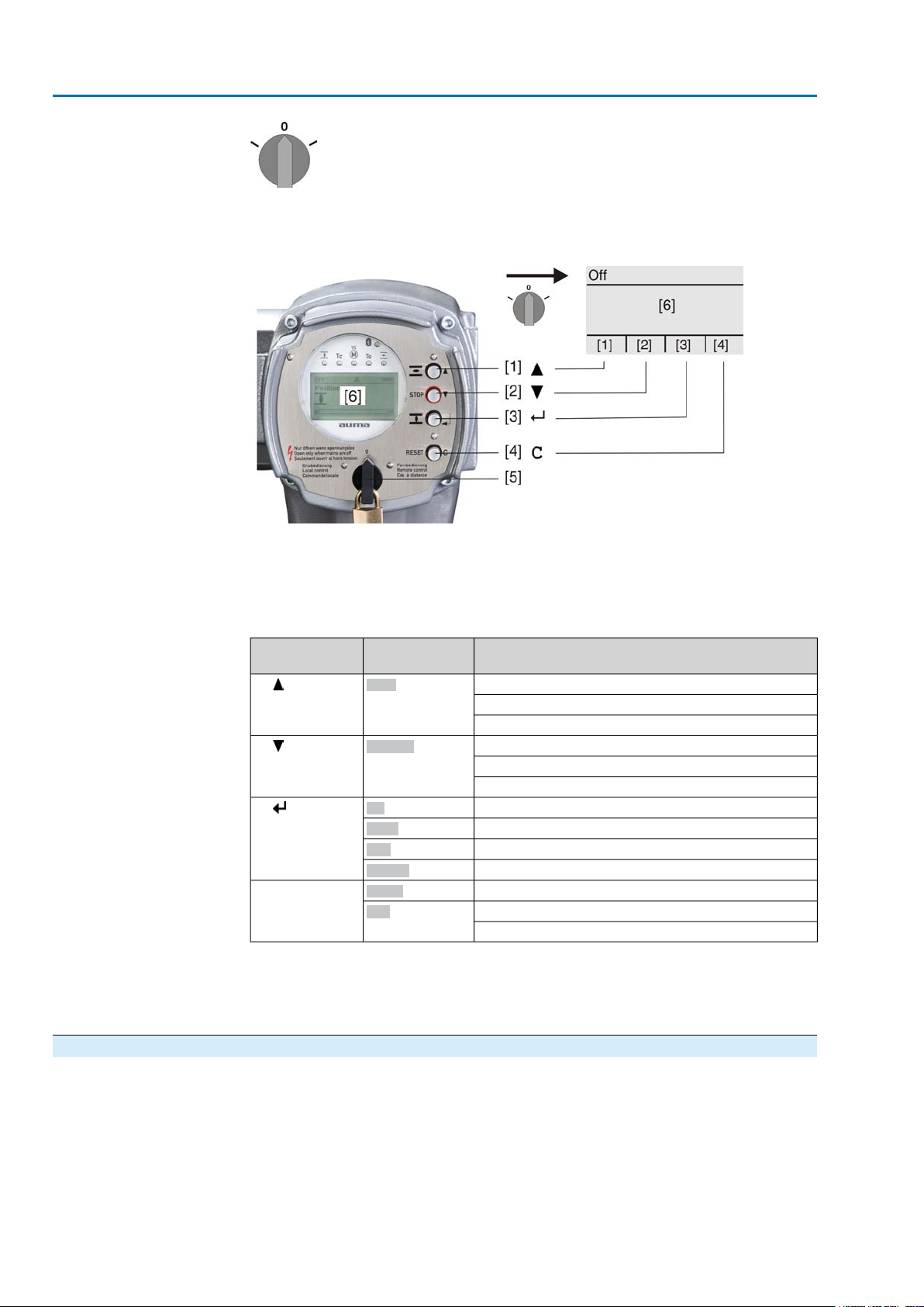
Menu navigation for display and setting is made via the push buttons [1 – 4] of the
local controls.
Set the selector switch [5] to position 0 (OFF) when navigating through the menu.
29
Page 30
SA 07.2 – SA 16.2 / SAR 07.2 – SAR 16.2 Control unit: electronic (MWG)
Operation AC 01.2 Non-Intrusive Modbus TCP/IP
The bottom row of the display [6] serves as navigation support and explains which
push buttons [1 – 4] are used for menu navigation.
Figure 26:
Backlight
[1–4] Push buttons or navigation support
[5] Selector switch
[6] Display
Table 7: Important push button functions for menu navigation
Push buttons
[1]
[2]
[3]
[4] C
●
The display is illuminated in white during normal operation.The backlight turns
port on display
Up ▲
Down ▼
Ok
Save
Edit
Details
Setup
Esc
FunctionsNavigation sup-
Change screen/selection
Change values
Enter figures from 0 to 9
Change screen/selection
Change values
Enter figures from 0 to 9
Confirm selection
Save
Enter <Edit> menu
Display more details
Enter Main menu
Cancel process
Return to previous display
to red under fault conditions.
●
The screen illumination is brighter when operating a push button. If no push
button is operated for 60 seconds, the display will become dim again.
6.3.1. Menu layout and navigation
Groups
30
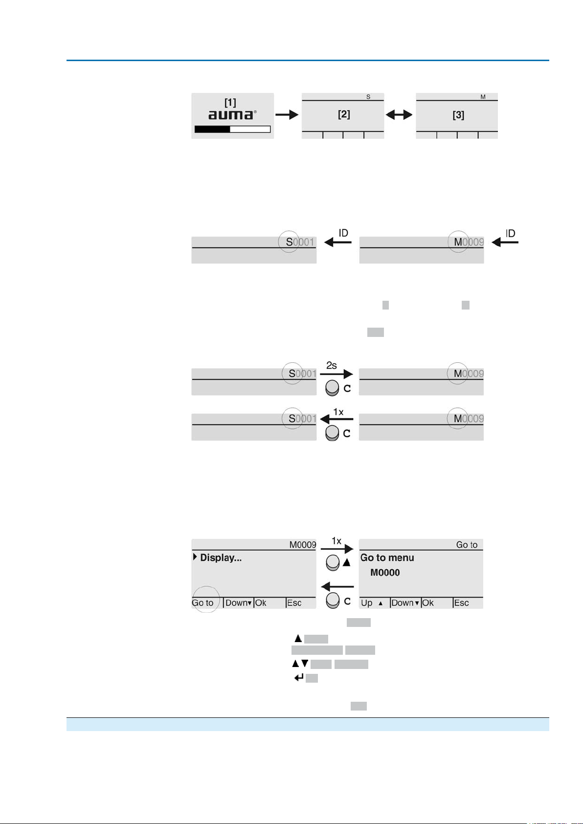
The indications on the display are divided into 3 groups:
Page 31
SA 07.2 – SA 16.2 / SAR 07.2 – SAR 16.2 Control unit: electronic (MWG)
AC 01.2 Non-Intrusive Modbus TCP/IP Operation
Figure 27: Groups
[1] Startup menu
[2] Status menu
[3] Main menu
Status menu and main menu are marked with an ID.
ID
Figure 28: Marking with ID
S
ID starts with S = status menu
M
ID starts with M = main menu
Group selection
Direct display via ID
It is possible to select between status menu S and main menu M:
For this, set selector switch to 0 (OFF), hold down push button C for approx. 2
seconds until a screen containing the ID M... appears.
Figure 29: Select menu groups
You return to the status menu if:
●
the push buttons on the local controls have not been oper ated within 10 minutes
●
or by briefly pressing C
When entering the ID within the main menu, screens can be displayed directly (without
clicking through).
Figure 30: Direct display (example)
Display indicates in the bottom row:Go to
1.
2.
3.
4. Repeat steps 2 and 3 for all further digits.
5.
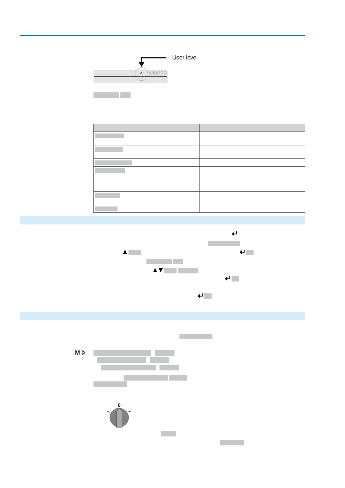
6.4. User level, password User level
The user level defines which menu items or par ameters can be displayed or modified
by the active user.
There are 6 different user levels.The user level is indicated in the top row:
Press push button Go to.
Display indicates:Go to menu M0000
Use push buttons Up ▲ Down ▼ to select figures 0 to 9.
Press push button Ok to confirm first digit.
To cancel the process: Press C Esc.
31
Page 32
SA 07.2 – SA 16.2 / SAR 07.2 – SAR 16.2 Control unit: electronic (MWG)
Operation AC 01.2 Non-Intrusive Modbus TCP/IP
Figure 31: User level display (example)
Password
6.4.1. Password entry
A password must be entered to allow par ameter modification.The display indicates:
Password 0***
A specific password is assigned to each user level and permits different actions.
Table 8: User levels and authorisations
Authorisation/passwordDesignation (user level)
Observer (1)
Operator (2)
Maintenance (3)
Specialist (4)
Service (5)
AUMA (6)
1.
Select desired menu and hold down push button for approx. 3 seconds.
Display indicates the set user level, e.g Observer (1)
➥
2.
Press Up ▲to select a higher user level and press Ok to confirm.
Display shows:Password 0***
➥
3.
Use push buttons Up ▲ Down ▼ to select figures 0 to 9.
4.
Confirm first digit of password via push button Ok.
Verify settings
No password required
Change settings
Default factory password: 0000
Reserved for future extensions
Change device configuration
e.g. type of seating, assignment of output
contacts
Default factory password: 0000
Service staff
Change configuration settings
AUMA administrator
5. Repeat steps 1 and 2 for all further digits.
Having confirmed the last digit with Ok, access to all parameters within one
➥
user level is possible if the password entry is correct.
6.4.2. Password change
Select main menu
32
Only the passwords of same or lower user level may be changed.
Example:The user is signed in as Specialist (4).This authorises him or her to modify
the passwords between user levels (1) to (4).
Device configuration M0053
Service functions M0222
Change passwords M0229
Menu point Service functions M0222 is only visible if user level has been set to
Specialist (4) or higher.
1. Set selector switch to position 0 (OFF).
2.
Press push button C Setup and hold it down for approx. 3 seconds.
Display goes to main menu and indicates:▶ Display...
➥
Page 33
SA 07.2 – SA 16.2 / SAR 07.2 – SAR 16.2 Control unit: electronic (MWG)
AC 01.2 Non-Intrusive Modbus TCP/IP Operation
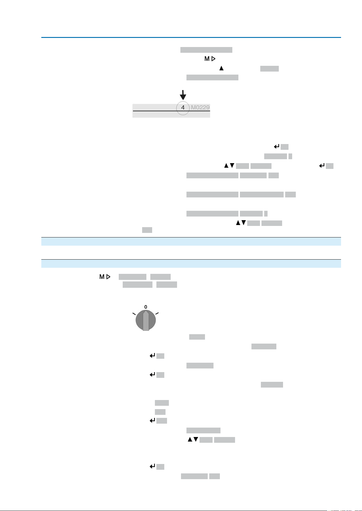
3.
Change passwords
Select parameter Change passwords either:
→
→
-
Display indicates:▶ Change passwords
click via the menu to parameter, or
via direct display: press and enter ID M0229
- The user level is indicated in the top row (1 – 6), e.g.:
- For user level 1 (view only), passwords cannot be changed.To change passwords, you must change to a higher user level. For this, enter a password via
a parameter.
4.
For a user level between 2 and 6: Press push button Ok.
The display indicates the highest user level, e.g.:For user 4
➥
5.
Select user level via push buttons Up ▲ Down ▼ and confirm with Ok.
Display indicates:▶ Change passwords Password 0***
➥
6.
Enter current password (→ enter password).
Display indicates:▶ Change passwords Password (new) 0***
➥
7.
Enter new password (→ enter password).
Display indicates:▶ Change passwords For user 4 (example)
➥
8.
Select next user lev el via push b uttons Up ▲ Down ▼ or cancel the process
via Esc.
6.5. Language in the display
The AUMATIC display is multilingual.
6.5.1. Language change
Display... M0009
Language M0049
Select main menu
Change language
1. Set selector switch to position 0 (OFF).
2.
➥
3.
➥
4.
➥
5. The bottom row of the display indicates:
6.
➥
7.
8.
➥
Press push button C Setup and hold it down for approx. 3 seconds.
Display goes to main menu and indicates:▶ Display...
Press Ok.
Display indicates:▶ Language
Press Ok.
Display indicates the selected language, e.g.:▶ Deutsch
→
→
Save → continue with step 10
Edit → continue with step 6
Press Edit.
Display indicates:▶ Observer (1)
Select user level via Up ▲ Down ▼ resulting in the following significations:
→
→
black triangle:▶ = current setting
white triangle: ▷ = selection (not saved yet)
Press Ok.
Display indicates:Password 0***
33
Page 34

SA 07.2 – SA 16.2 / SAR 07.2 – SAR 16.2 Control unit: electronic (MWG)
Operation AC 01.2 Non-Intrusive Modbus TCP/IP
9.
Enter password (→ enter password).
Display indicates:▶ Language and Save (bottom row)
➥
10.
Language selection
Select new language via Up ▲ Down ▼ resulting in the following significations:
→
→
11.
Confirm selection via Save.
The display changes to the new language.The new language selection is saved.
➥
black triangle:▶ = current setting
white triangle: ▷ = selection (not saved yet)
34
Page 35
SA 07.2 – SA 16.2 / SAR 07.2 – SAR 16.2 Control unit: electronic (MWG)
AC 01.2 Non-Intrusive Modbus TCP/IP Indications
7. Indications
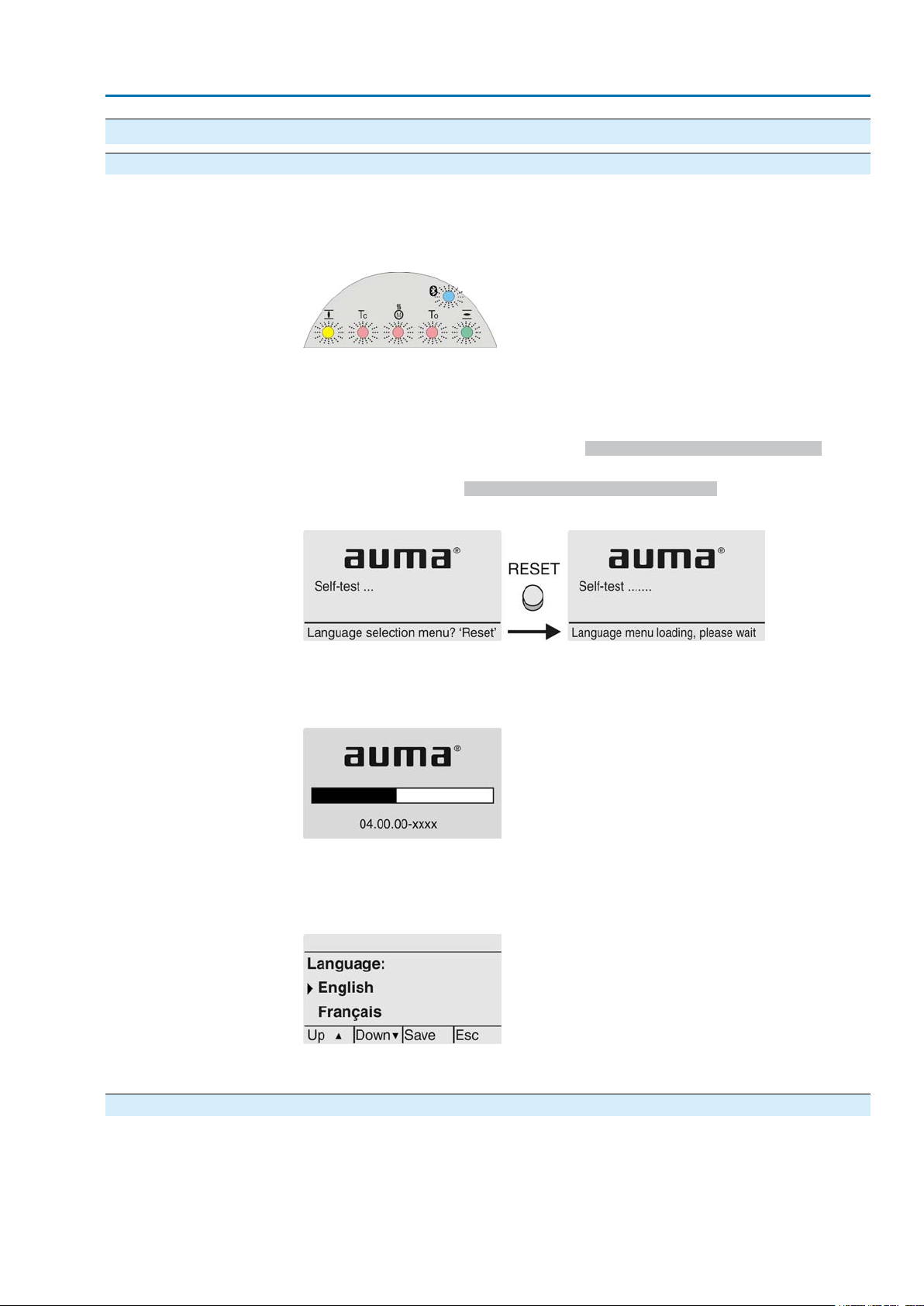
7.1. Indications during commissioning LED test
Language selection
When switching on the power supply, all LEDs on the local controls illuminate for
approx. 1 second.This optical feedbac k indicates that the voltage supply is connected
to the controls and all LEDs are operable.
Figure 32: LED test
During the self-test, the language selection can be activated so that the selected
language is immediately indicated in the display. For this, set selector switch [5] to
position 0 (OFF).
Activate language selection:
1.
Display indicates in the bottom row:Language selection menu? 'Reset'
2. Press push button RESET and hold it down until the following te xt is displayed
in the bottom line: Language menu loading, please wait.
Figure 33: Self-test
Startup menu
The language selection menu follows the startup menu.
The current firmware version is displayed during the startup procedure:
Figure 34: Startup menu with firmware version: 04.00.00–xxxx
If the language selection feature has been activated during the self-test, the menu
for selecting the display language will now be indicated. For further information on
language setting, please refer to chapter <Language in the display>.
Figure 35: Language selection
If no entry is made over a longer period of time (approx. 1 minute), the display
automatically returns to the first status indication.
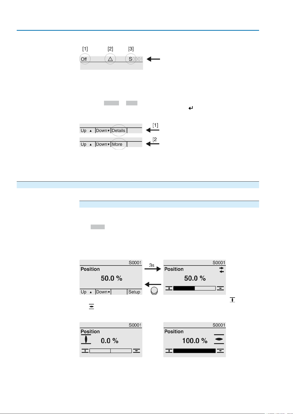
7.2. Indications in the display Status bar
The status bar (first row in the display) indicates the operation mode [1], the presence
of an error [2] and the ID number [3] of the current display indication.
35
Page 36
SA 07.2 – SA 16.2 / SAR 07.2 – SAR 16.2 Control unit: electronic (MWG)
Indications AC 01.2 Non-Intrusive Modbus TCP/IP
Figure 36: Information in the status bar (top)
[1] Operation mode
[2] Error symbol (only for faults and warnings)
[3] ID number: S = Status page
Navigation support
If further details or information are available with reference to the displa y, the following
indications Details or More appear in the navigation support (bottom display row).
Then, further information can be displayed via the push button.
Figure 37: Navigation support (bottom)
[1] shows list with detailed indications
[2] shows further available information
The navigation support (bottom row) is faded out after approx. 3 seconds. Press any
push button (selector switch in position 0 (OFF)) to fade in the navigation support.
7.2.1. Feedback indications from actuator and valve
Display indications depend on the actuator version.
Valve position (S0001)
This indication is only available if a position transmitter (potentiometer, RWG or
MWG) is installed in the actuator.
●
S0001 on the display indicates the valve position in % of the travel.
●
The bargraph display appears after approx. 3 seconds.
●
When issuing an operation command, an arrow indicates the direction
(OPEN/CLOSE).
Figure 38:Valve position and direction of operation
Reaching the preset end positions is additionally indicated via symbols (CLOSED)
and (OPEN).
Figure 39: End position CLOSED/OPEN reached
0% Actuator is in end position CLOSED
100% Actuator is in end position OPEN
36
Page 37
SA 07.2 – SA 16.2 / SAR 07.2 – SAR 16.2 Control unit: electronic (MWG)
AC 01.2 Non-Intrusive Modbus TCP/IP Indications
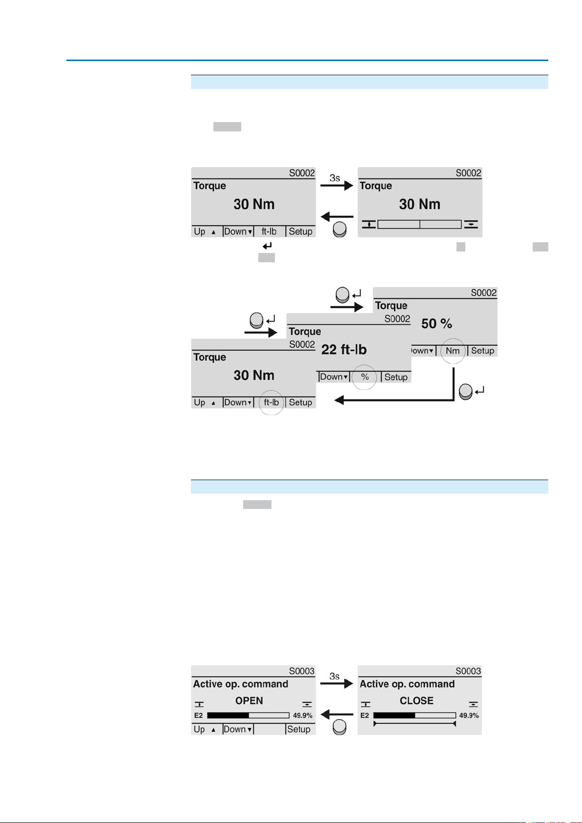
Torque (S0002)
The indication is only available if the actuator is equipped with an MWG (magnetic
limit and torque transmitter).
●
S0002 on the display indicates the torque applied at the actuator output.
●
The bargraph display appears after approx. 3 seconds.
Figure 40:Torque
Select unit
Display in percent
OPEN - CLOSE control
The push button allows to select the unit displayed (percent %, Newton metre Nm
or "foot-pound" ft-lb
Figure 41: Units of torque
100 % indication equals the max. torque indicated on the name plate of the actuator .
Example: SA 07.5 with 20 – 60 Nm.
●
100 % corresponds to 60 Nm of nominal torque.
●
50 % corresponds to 30 Nm of nominal torque.
Operation commands (S0003)
The display S0003 indicates:
●
active operation commands, lik e e.g.: Operation in direction CLOSE or in direction OPEN
●
the actual value E2 as bargraph indication and as v alue between 0 and 100 %.
●
for setpoint control (positioner): setpoint E1
●
for stepping mode or for intermediate positions with operation profile: pivot
points and operation behaviour of pivot points
The navigation support (bottom row) is faded out after approx. 3 seconds and the
axis/axes for pivot point display are shown.
Active operation commands (OPEN, CLOSE, ...) are shown above the bargraph
display. The figure below shows the operation command in direction CLOSE.
Figure 42: Display for OPEN - CLOSE control
E2 Actual position value
37
Page 38
SA 07.2 – SA 16.2 / SAR 07.2 – SAR 16.2 Control unit: electronic (MWG)
Indications AC 01.2 Non-Intrusive Modbus TCP/IP
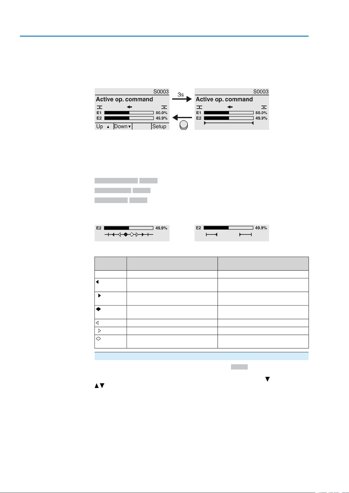
Setpoint control
Pivot point axis
If the positioner is enabled and activated, the bargraph indication for E1 (position
setpoint) is displayed.
The direction of the operation command is displayed b y an arrow above the barg raph
indication.The figure below shows the operation command in direction CLOSE.
Figure 43: Display for setpoint control (positioner)
E1 Position setpoint
E2 Actual position value
The pivot points and their operation behaviour (operation profile) are shown on the
pivot point axis by means of symbols.
The symbols are only displayed if at least one of the f ollo wing functions is activ ated:
Operation profile M0294
Timer CLOSE M0156
Timer OPEN M0206
Figure 44: Examples: on the left pivot points (intermediate positions); on the right
stepping mode
Table 9: Symbols along the pivot point axis
Symbol
with operation profile
Stop during operation in direction
CLOSE
Stop during operation in direction
OPEN
OPEN and CLOSE
and CLOSE
Stepping modePivot point (intermediate position)
End of stepping modePivot point without reaction|
Start of stepping mode in direction
CLOSE
Start of stepping mode in direction
OPEN
–Stop during operation in directions
–Pause for oper ation in direction CLOSE
–Pause for oper ation in direction OPEN
–Pause for oper ation in directions OPEN
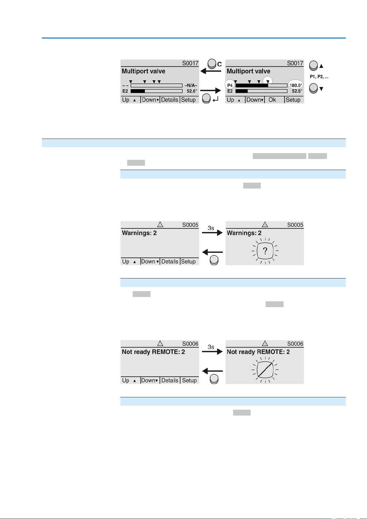
Multiport valve positions (S0017)
In case of active multiport valve function, the display S0017 indicates a second
bargraph display with set positions (valve connections) above the actual position
value E2. Positions (P1, P2, ...) are displayed with a black triangle . Push buttons
are used to select positions. Both positions and the actual position v alue E2 are
displayed in degrees.
38
Page 39
SA 07.2 – SA 16.2 / SAR 07.2 – SAR 16.2 Control unit: electronic (MWG)
AC 01.2 Non-Intrusive Modbus TCP/IP Indications
Figure 45: Status indication for multiport valve (example P4 = 180°)
P (P1, P2, ...) selected position (1, 2, ...)
(– –) no position selected
E2 Actual position value
7.2.2. Status indications according to AUMA classification
These indications are available, if the parameter Diagnostic classific. M0539 is set
to AUMA.
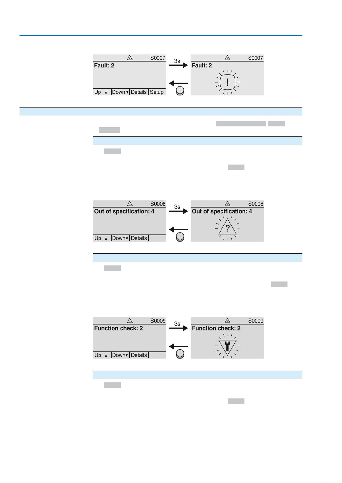
Warnings (S0005)
If a warning has occurred, the display shows S0005:
●
the number of warnings occurred
●
a blinking question mark after approx. 3 seconds
Figure 46:Warnings
For further information, please also refer to <Corrective action>.
Not ready REMOTE (S0006)
The S0006 display shows indications of the Not ready REMOTE group.
If such an indication has occurred, the display shows S0006:
●
the number of indications occurred
●
a blinking crossbar after approx. 3 seconds
Figure 47: Not ready REMOTE indications
For further information, please also refer to <Corrective action>.
Fault (S0007)
If a fault has occurred, the display shows S0007:
●
the number of faults occurred
●
a blinking exclamation mark after approx. 3 seconds
39
Page 40
SA 07.2 – SA 16.2 / SAR 07.2 – SAR 16.2 Control unit: electronic (MWG)
Indications AC 01.2 Non-Intrusive Modbus TCP/IP
Figure 48: Fault
For further information, please also refer to <Corrective action>.
7.2.3. Status indications according to NAMUR recommendation
These indications are available, if the parameter Diagnostic classific. M0539 is set
to NAMUR.
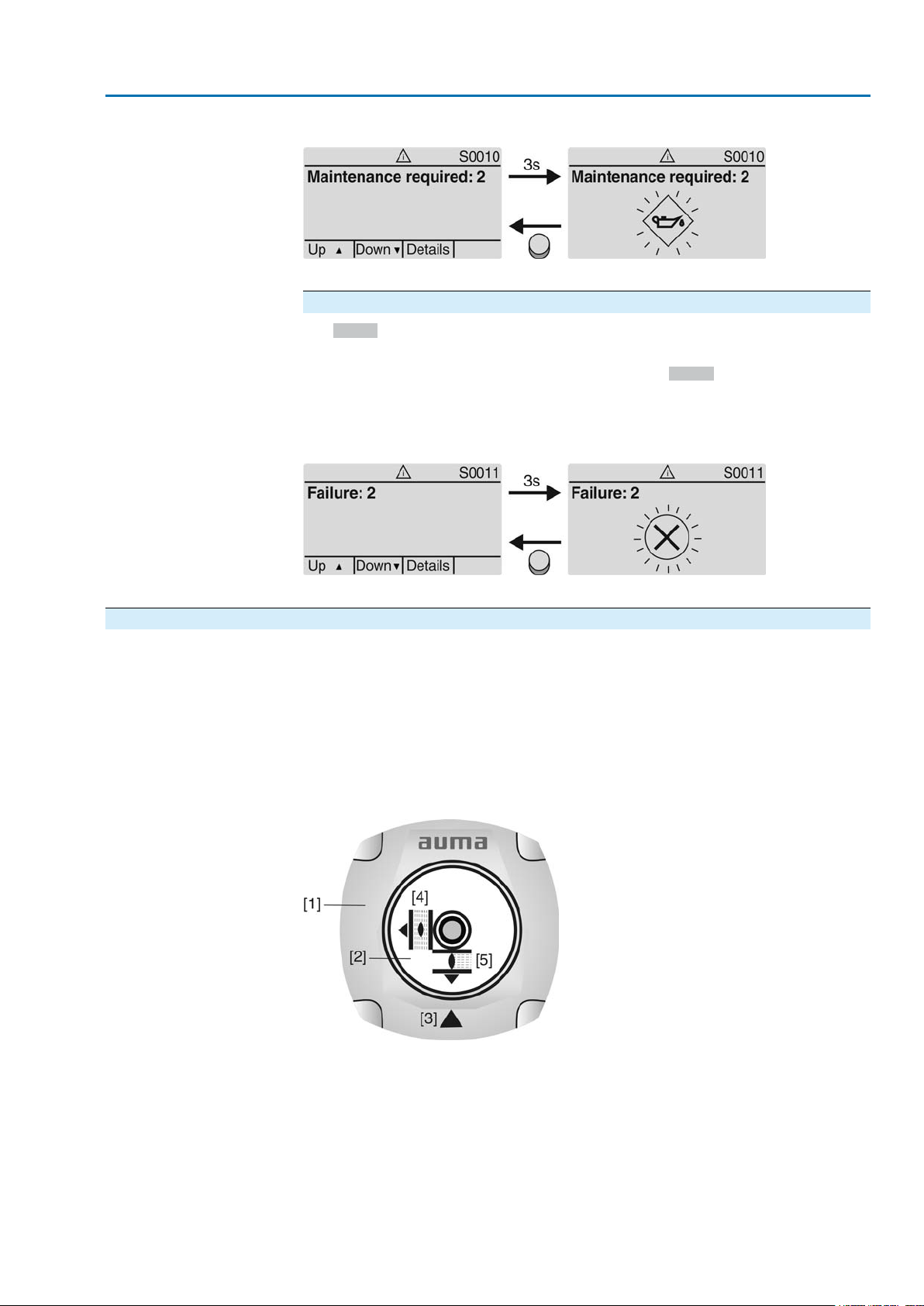
Out of Specification (S0008)
The S0008 indication shows out of specification indications according to NAMUR
recommendation NE 107.
If such an indication has occurred, the display shows S0008:
●
the number of indications occurred
●
a blinking triangle with question mark after approx. 3 seconds
Figure 49: Out of specification
For further information, please also refer to <Corrective action>.
Function check (S0009)
The S0009 indication shows function check indications according to NAMUR
recommendation NE 107.
If an indication has occurred via the function check, the display shows S0009:
●
the number of indications occurred
●
a blinking triangle with a spanner after approx. 3 seconds
Figure 50: Function check
For further information, please also refer to <Corrective action>.
Maintenance required (S0010)
The S0010 indication shows maintenance indications according to NAMUR
recommendation NE 107.
If such an indication has occurred, the display shows S0010:
●
the number of indications occurred
●
a blinking square with an oil can after approx. 3 seconds
40
Page 41
SA 07.2 – SA 16.2 / SAR 07.2 – SAR 16.2 Control unit: electronic (MWG)
AC 01.2 Non-Intrusive Modbus TCP/IP Indications
Figure 51: Maintenance required
For further information, please also refer to <Corrective action>.
Failure (S0011)
The S0011 indication shows the causes of the failure indication according to NAMUR
recommendation NE 107.
If such an indication has occurred, the display shows S0011:
●
the number of indications occurred
●
a blinking circle with a cross after approx. 3 seconds
Figure 52: Failure
For further information, please also refer to <Corrective action>.
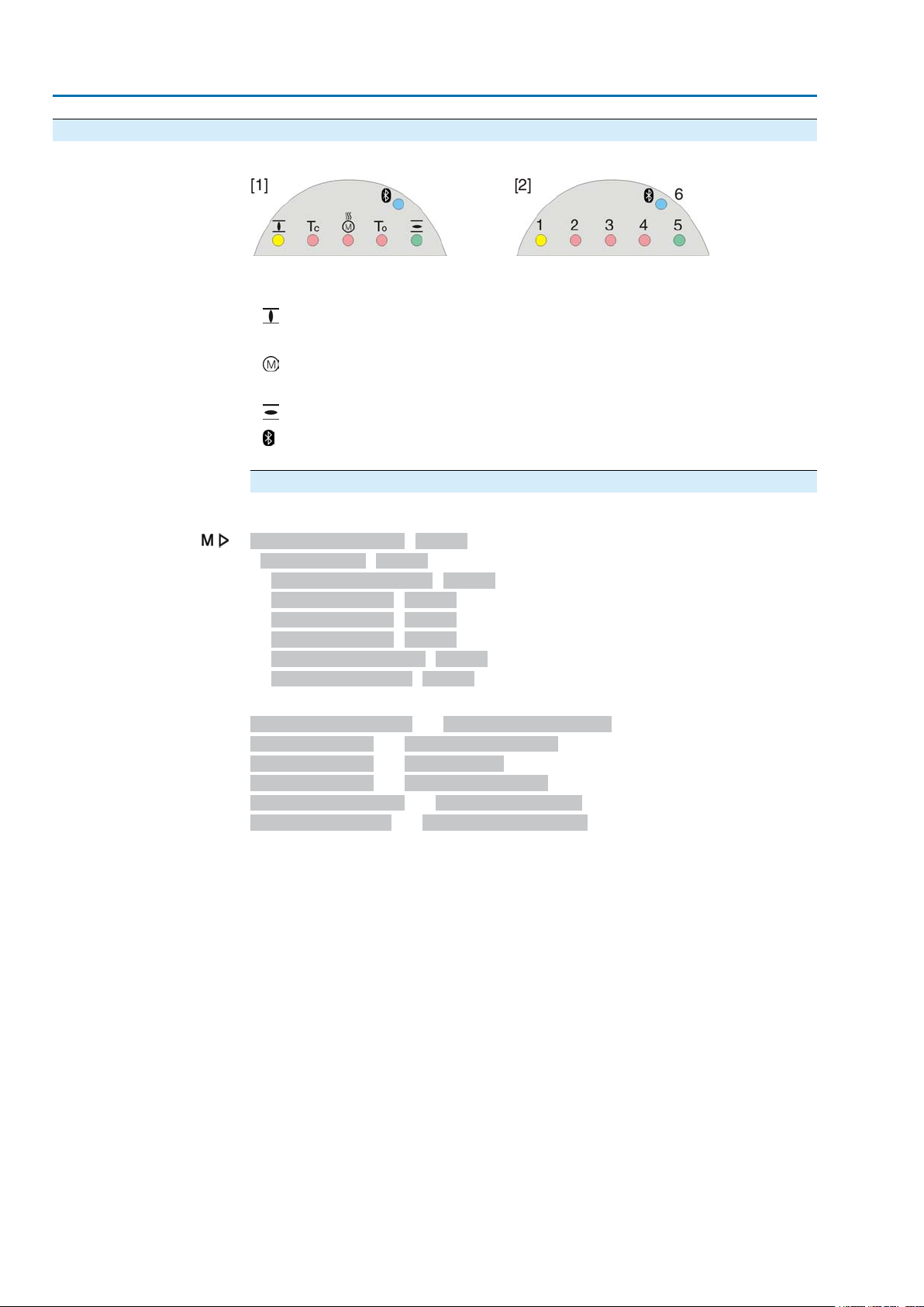
7.3. Mechanical position indicator/running indication
— Option —
Mechanical position indicator:
●
Continuously indicates the valve position
(For complete travel from OPEN to CLOSED or vice versa, the indicator disc
[2] rotates by approximately 180° to 230°.)
●
Indicates whether the actuator is running (running indication)
●
Indicates that the end positions are reached (via indicator mark [3])
Figure 53: Mechanical position indicator
[1] Cover
[2] Indicator disc
[3] Mark
[4] Symbol for position OPEN
[5] Symbol for position CLOSED
41
Page 42
SA 07.2 – SA 16.2 / SAR 07.2 – SAR 16.2 Control unit: electronic (MWG)
Indications AC 01.2 Non-Intrusive Modbus TCP/IP
7.4. Indication lights
Figure 54: Arrangement and signification of indication lights
[1] Marking with symbols (standard)
[2] Marking with figures 1 – 6 (option)
End position CLOSED reached (blinking: for operation in direction CLOSE)
1
2 Tc Torque fault CLOSE
Motor protection tripped
3
4 To Torque fault OPEN
End position OPEN reached (blinking: for operation in direction OPEN)
5
Bluetooth connection
6
Modify indication light assignment (indications)
Different indications can be assigned to LEDs 1 – 5.
Device configuration M0053
Local controls M0159
Indication light 1 (left) M0093
Indication light 2 M0094
Indication light 3 M0095
Indication light 4 M0096
Indicat. light 5 (right) M0097
Signal interm. pos. M0167
Defaut values (Europe):
Indication light 1 (left) = End p. CLOSED, blink
Indication light 2 = Torque fault CLOSE
Indication light 3 = Thermal fault
Indication light 4 = Torque fault OPEN
Indicat. light 5 (right) = End p. OPEN, blink
Signal interm. pos. = OPEN/CLOSED = Off
Further setting values:
Refer to Manual (Operation and setting).
42
Page 43
SA 07.2 – SA 16.2 / SAR 07.2 – SAR 16.2 Control unit: electronic (MWG)
AC 01.2 Non-Intrusive Modbus TCP/IP Signals
8. Signals
8.1. Status signals via output contacts (digital outputs)
— (Option) —
Output contacts are only available if a par allel interf ace is pro vided in addition to the
communication interface.
Characteristics
8.1.1. Assignment of outputs
Output contacts are used to send status signals (e.g. reaching the end positions,
selector switch position, faults...) as binary signals to the control room.
Status signals only have two states: active or inactive. Active means that the
conditions for the signal are fulfilled.
The output contacts (outputs DOUT 1 – 6) can be assigned to various signals.
Required user level:Specialist (4) or higher.
Device configuration M0053
I/O interface M0139
Digital outputs M0110
Signal DOUT 1 M0109
8.1.2. Coding the outputs
8.2. Analogue signals
Valve position
Torque feedback
Default values:
Signal DOUT 1 = Fault
Signal DOUT 2 = End position CLOSED
Signal DOUT 3 = End position OPEN
Signal DOUT 4 = Selector sw. REMOTE
Signal DOUT 5 = Torque fault CLOSE
Signal DOUT 6 = Torque fault OPEN
The output signals DOUT 1 – 6 can be set either to high active or low active.
●
High active = output contact closed = signal active
●
Low active = output contact open = signal active
Required user level:Specialist (4) or higher.
Device configuration M0053
I/O interface M0139
Digital outputs M0110
Coding DOUT 1 M0102
Default values for DOUT 1 – 6: High active
— (Option) —
Analogue feedback signals are only a vailable if additional input signals are pro vided.
Signal: E2 = 0/4 – 20 mA (galvanically isolated)
Designation in the wiring diagram:
ANOUT1 (position)
Signal: E6 = 0/4 – 20 mA (galvanically isolated)
Designation in the wiring diagram:
ANOUT2 (torque)
For further information on this topic, please refer to Manual (Operation and setting).
43
Page 44
SA 07.2 – SA 16.2 / SAR 07.2 – SAR 16.2 Control unit: electronic (MWG)
Commissioning (basic settings) AC 01.2 Non-Intrusive Modbus TCP/IP
9. Commissioning (basic settings)
1. Set selector switch to position 0 (OFF).
Information: The selector switch is not a mains switch.When positioned to 0
(OFF), the actuator cannot be operated.The controls' power supply is
maintained.
2. Switch on the power supply.
Information:Please consider the heat-up time for ambient temperatures below
–20 °C.
3. Perform basic settings.
9.1. Type of seating: set
Valve damage due to incorrect setting!
→
The type of seating must suit the valve.
→
Only change the setting with the consent of the valve manufacturer.
Limit
Torque
Select main menu
Select parameter
CLOSE or OPEN
Customer settings M0041
Type of seating M0012
End position CLOSED M0086
End position OPEN M0087
Default value: Limit
Setting values:
Seating in end positions via limit switching.
Seating in end positions via torque switching.
1. Set selector switch to position 0 (OFF).
2.
Press push button C Setup and hold it down for approx. 3 seconds.
Display goes to main menu and indicates:▶ Display...
➥
3. Select parameter either:
→
→
Display indicates:End position CLOSED
➥
4.
Use Up ▲ Down ▼ to select:
→
→
The black triangle ▶ indicates the current selection.
➥
5.
Press Ok.
Display indicates the current setting:Limit or Torque
➥
The bottom row of the display indicates either:
➥
-
Edit → continue with step 6
-
Save → continue with step 10
click via the menu to parameter, or
via direct display: press and enter ID M0086 or M0087
▶ End position CLOSED
▶ End position OPEN
44
Page 45
SA 07.2 – SA 16.2 / SAR 07.2 – SAR 16.2 Control unit: electronic (MWG)
AC 01.2 Non-Intrusive Modbus TCP/IP Commissioning (basic settings)
6.
Press Edit.
Display indicates:▶ Specialist (4)
➥
7.
Log on user
Change settings
Use Up ▲ Down ▼ to select user:
Information: Required user level: Specialist (4) or higher
The symbols have the following meaning:
➥
-
black triangle:▶ = current setting
-
white triangle: ▷ = selection (not saved yet)
8.
Press Ok.
Display indicates:Password 0***
➥
9.
Enter password (→ enter password).
The screen indicates the pre-set type of seating (▶ Limit or ▶ Torque) by means
➥
of a black triangle ▶.
10.
Select new setting Up ▲ Down ▼ resulting in the following significations:
The symbols have the following meaning:
➥
-
black triangle:▶ = current setting
-
white triangle: ▷ = selection (not saved yet)
11.
Confirm selection via Save.
The setting for the type of seating is complete.
➥
12.
Back to step 4 (CLOSED or OPEN): Press Esc .
9.2. Torque switching: set
Once the set torque is reached, the torque switches will be tripped (overload protection
of the valve).
Information The torque switches may also trip during manual operation.
Valve damage due to excessive tripping torque limit setting!
→
→
Customer settings M0041
Torque switching M0013
Default value: According to order data
Setting range: Torque range according to actuator name plate
Select main menu
1. Set selector switch to position 0 (OFF).
The tripping torque must suit the valve.
Only change the setting with the consent of the valve manufacturer.
Trip torque CLOSE M0088
Trip torque OPEN M0089
Select parameter
2.
Press push button C Setup and hold it down for approx. 3 seconds.
Display goes to main menu and indicates:▶ Display...
➥
3. Select parameter either:
→
→
Display indicates:Trip torque CLOSE
➥
click via the menu to parameter, or
via direct display: press and enter ID M0084.
45
Page 46
SA 07.2 – SA 16.2 / SAR 07.2 – SAR 16.2 Control unit: electronic (MWG)
Commissioning (basic settings) AC 01.2 Non-Intrusive Modbus TCP/IP
4.
CLOSE or OPEN
User login
Use Up ▲ Down ▼ to select:
→
→
The black triangle ▶ indicates the current selection.
➥
5.
Press Ok.
Display shows the set value.
➥
The bottom row indicates: Edit Esc
➥
6.
Press Edit.
Display indicates:
➥
-
Specialist (4) → continue with step 7
-
in bottom row Up ▲ Down ▼ Esc → continue with step 11
7.
Use Up ▲ Down ▼ to select user:
▶ Trip torque CLOSE
▶ Trip torque OPEN
Information: Required user level: Specialist (4) or higher.
The symbols have the following meanings:
➥
-
black triangle:▶ = current setting
-
white triangle: ▷ = selection (not saved yet)
8.
Press Ok.
Display indicates:Password 0***
➥
9.
Enter password (→ enter password).
Display shows the set value.
➥
The bottom row indicates: Edit Esc
➥
10.
Press Edit.
11.
Change value
Enter new value for tripping torque via Up ▲ Down ▼.
Information: The adjustable torque range is shown in round brackets.
12.
Save new value via Save.
The tripping torque is set.
➥
13.
Back to step 4 (CLOSED or OPEN): Press Esc.
Information The following f ault signals are issued if the torque setting performed has been reached
in mid-travel:
●
The fault has to be acknowledged before the operation can be resumed.The
acknowledgement is made:
1. either by an operation command in the opposite direction.
2. or, in case the torque applied is lower than the preset tripping torque:
9.3. Limit switching: set
Customer settings M0041
In the display of the local controls: Status indication S0007
Torque fault OPEN or Torque fault CLOSE
-
For Torque fault OPEN : Operation command in direction CLOSE
-
For Torque fault CLOSE : Operation command in direction OPEN
- On the local controls using the push button RESET (in selector switch
position Local Control (LOCAL) .
Valve damage at valve/gearbox due to incorrect setting!
→
When setting with motor operation: Stop actuator bef ore reaching end of tra v el
(press push button STOP).
→
Allow for overrun when selecting limit seating.
46
Page 47
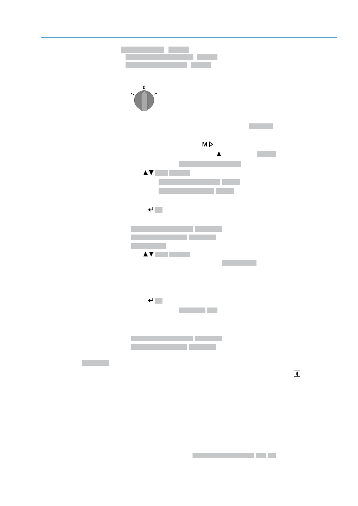
SA 07.2 – SA 16.2 / SAR 07.2 – SAR 16.2 Control unit: electronic (MWG)
AC 01.2 Non-Intrusive Modbus TCP/IP Commissioning (basic settings)
Limit switching M0010
Set end pos.CLOSED? M0084
Set end pos. OPEN? M0085
Select main menu
Select parameter
CLOSED or OPEN
Log on user
1. Set selector switch to position 0 (OFF).
2. Press push button C and hold it down for approx. 3 seconds.
Display goes to main menu and indicates:▶ Display...
➥
3. Select parameter either:
→
→
Display indicates:Set end pos.CLOSED?
➥
4.
Use Up ▲ Down ▼ to select:
→
→
The black triangle ▶ indicates the current selection.
➥
5.
Press Ok.
The display indicates either:
➥
-
Set end pos.CLOSED? CMD0009 → continue with step 9
-
Set end pos. OPEN? CMD0010 → continue with step 14
-
Specialist (4) → continue with step 6
6.
Use Up ▲ Down ▼ to select a user:
Information: Required user level: Specialist (4) or higher
click via the menu to parameter, or
via direct display: press and enter ID M0084.
▶ Set end pos.CLOSED? M0084
▶ Set end pos. OPEN? M0085
Set end position
CLOSED CMD0009
The symbols have the following meaning:
➥
-
black triangle:▶ = current setting
-
white triangle: ▷ = selection (not saved yet)
7.
Press Ok to confirm selected user level.
Display indicates:Password 0***
➥
8.
Enter password (→ enter password).
The display indicates either:
➥
-
Set end pos.CLOSED? CMD0009 → continue with step 9
-
Set end pos. OPEN? CMD0010 → continue with step 14
9. Re-set end position CLOSED:
9.1 For large strokes: Set selector switch in position Local control (LOCAL)
and operate actuator in motor operation via push button (CLOSED) in
direction of the end position.
Information: Stop actuator before reaching end of travel (press push
button STOP) to avoid damage.
9.2 Engage manual operation.
9.3 Turn handwheel until valve is closed.
9.4 Turn handwheel by approximately half a turn (overrun) in the opposite
direction of end position.
9.5 Set selector switch to position 0 (OFF).
Display indicates:Set end pos.CLOSED? Yes No
➥
47
Page 48
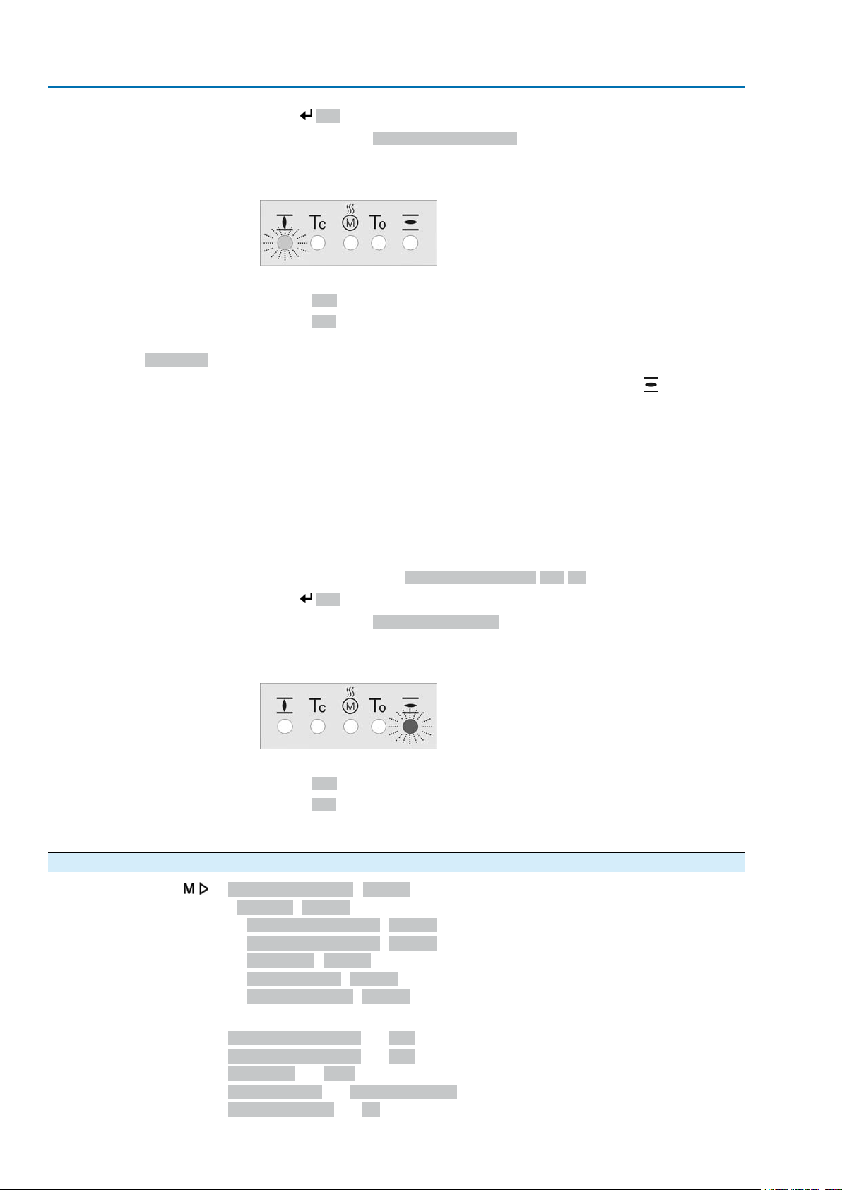
SA 07.2 – SA 16.2 / SAR 07.2 – SAR 16.2 Control unit: electronic (MWG)
Commissioning (basic settings) AC 01.2 Non-Intrusive Modbus TCP/IP
10.
Press Yes to accept new end position setting.
Display indicates:End pos. CLOSED set!
➥
The left LED is illuminated (standard version) and thus indicates that the end
➥
position CLOSED setting is complete.
11. Make selection:
Set end position OPEN
CMD0010
→
→
12. Re-set end position OPEN:
12.1 For large strokes: Set selector switch in position Local control (LOCAL)
Edit → back to step 9: Set end position CLOSED "once again"
Esc → back to step 4; either set end position OPEN or exit the menu.
and operate actuator in motor operation via push button (OPEN) in
direction of the end position.
Information: Stop actuator before reaching end of travel (press push
button STOP) to avoid damage.
12.2 Engage manual operation.
12.3 Turn handwheel until valve is open.
12.4 Turn handwheel by approximately half a turn (overrun) in the opposite
direction of end position.
12.5 Set selector switch to position 0 (OFF).
Display indicates:Set end pos. OPEN? Yes No
➥
13.
Press Yes to accept new end position setting.
Display indicates:End pos. OPEN set!
➥
The right LED is illuminated (standard version) and thus indicates that the end
➥
position setting is complete.
14. Make selection:
→
→
Information If an end position cannot be set: Check the type of control unit in actuator.
9.4. Bus address (slave address), baud rate, parity and monitoring time: set
Edit → back to step 9: Set end position OPEN "once again"
Esc → back to step 4; either set end position CLOSED or exit the menu.
Customer settings M0041
Modbus M0341
MD1 slave address M0247
MD2 slave address M0409
Baud rate M0343
Parity/stop bit M0782
Monitoring time M0781
Default values:
MD1 slave address = 247
MD2 slave address = 247
Baud rate = Auto
Parity/stop bit = Even, 1 stop bit
Monitoring time = 15 seconds
48
Page 49
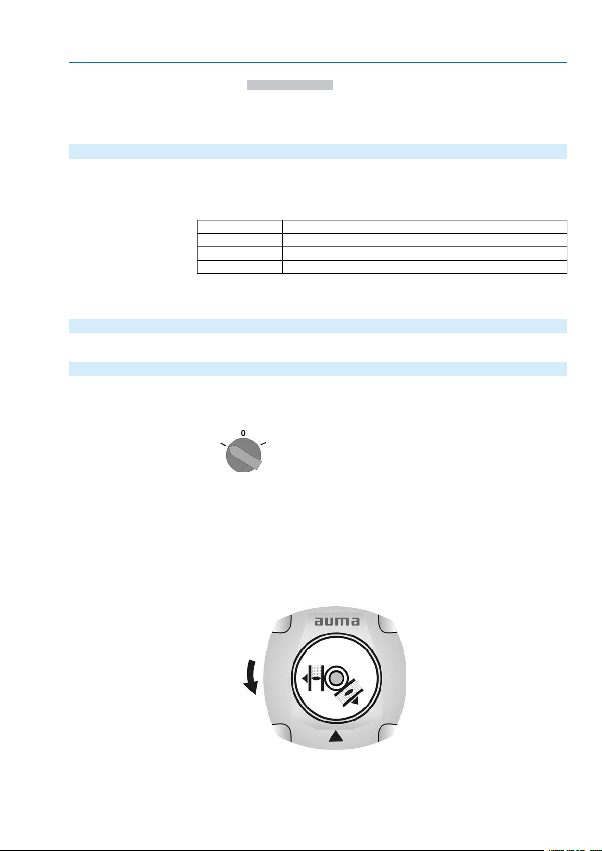
SA 07.2 – SA 16.2 / SAR 07.2 – SAR 16.2 Control unit: electronic (MWG)
AC 01.2 Non-Intrusive Modbus TCP/IP Commissioning (basic settings)
Information
Parameter MD2 slave address is only available if AUMA redundancy I (option) is
available.
For further settings and information e.g. on redundancy, refer to Manual (Device
integration).
9.4.1. Modbus TCP/IP Gateway: set
Modbus TCP/IP gateway settings can be adapted by means of a web server.
Login password (default setting in the factory): admin
Table 10: Default setting of the IP interface:
If required, only the IP interface must be adapted to the requirements of the Modbus
TCP/IP network. All further settings of the Modbus TCP/IP gateway (particularly the
port settings) are set as default in the factory.
9.5. Test run
Perform test run only once all settings previously described have been performed.
9.5.1. Direction of rotation: check
Static IPAddress Type
192.168.255.1Static IP Address
255.255.0.0Subnet Mask
192.168.0.1Default Gateway
1. Move actuator manually to intermediate position or to sufficient distance from
end position.
2. Set selector switch to position Local control (LOCAL).
3. Switch on actuator in running direction CLOSE and observe the direction of
rotation:
with indicator disc: step 4
without indicator disc: step 5 (hollow shaft)
→
Switch off before reaching the end position.
4. With indicator disc:
→
Observe direction of rotation.
The direction of rotation is correct, if actuator runs in direction CLOSE
➥
and indicator disc turns counterclockwise.
49
Page 50
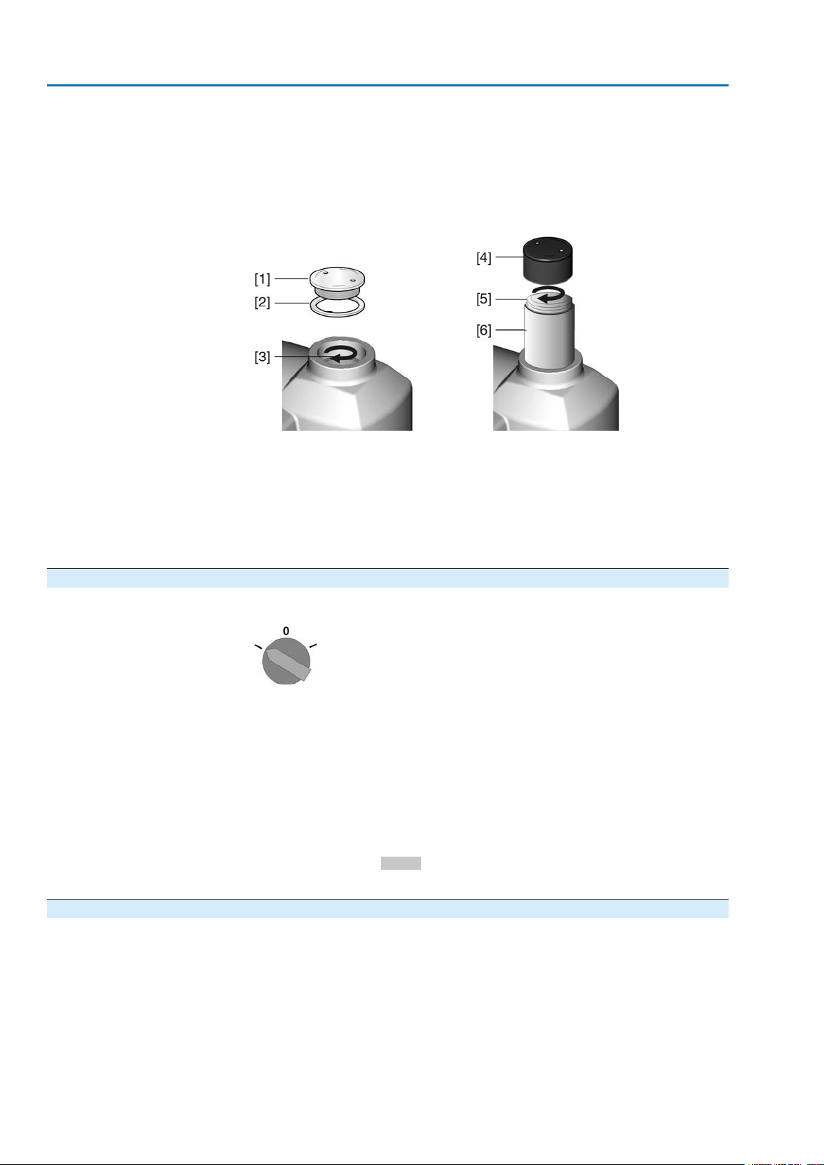
SA 07.2 – SA 16.2 / SAR 07.2 – SAR 16.2 Control unit: electronic (MWG)
Commissioning (basic settings) AC 01.2 Non-Intrusive Modbus TCP/IP
5. Without the indicator disc:
→
Unscrew threaded plug [1] and seal [2] or cap for stem protection tube [4]
and observe direction of rotation at hollow shaft [3] or the stem [5].
The direction of rotation is correct, if actuator runs in direction CLOSE and
➥
hollow shaft or stem turn clockwise.
Figure 55: Hollow shaft/stem
[1] Threaded plug
[2] Seal
[3] Hollow shaft
[4] Cap for stem protection tube
[5] Stem
[6] Stem protection tube
9.5.2. Limit switching: check
1. Set selector switch to position Local control (LOCAL).
2. Operate actuator using push buttons OPEN, STOP, CLOSE.
The limit switching is set correctly if (default indication):
➥
- the yellow indication light/LED1 is illuminated in end position CLOSED
- the green indication light/LED5 is illuminated in end position OPEN
- the indication lights go out after travelling into opposite direction.
The limit switching is set incorrectly if:
➥
- the actuator comes to a standstill before reaching the end position
- one of the red indication lights/LEDs is illuminated (torque fault)
-
the status indication S0007 in the display signals a fault.
3. If the end position setting is incorrect: Reset limit switching.
9.6. Switch compartment: open
The switch compartment must be opened to perform the following settings (options).
50
Page 51
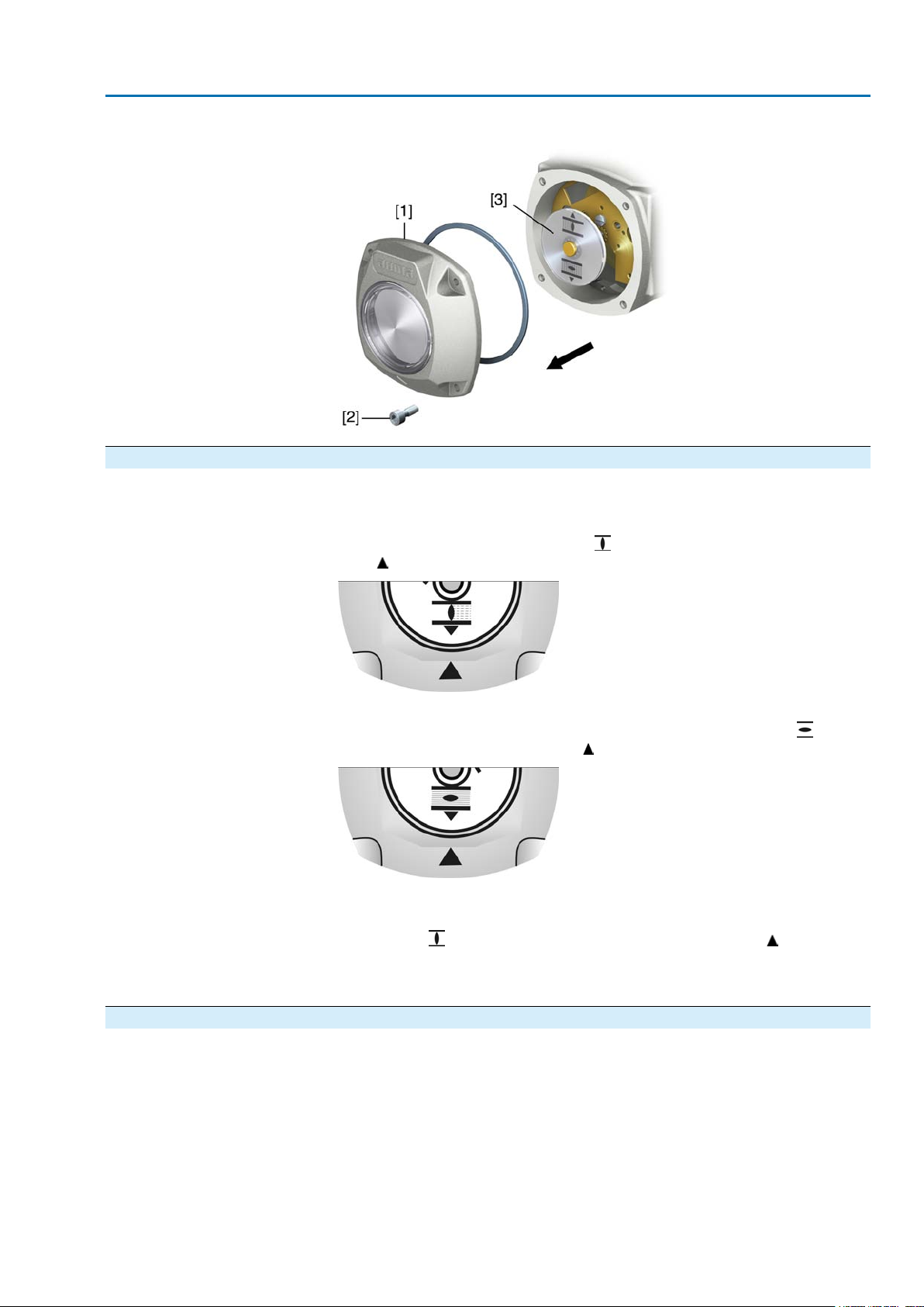
SA 07.2 – SA 16.2 / SAR 07.2 – SAR 16.2 Control unit: electronic (MWG)
AC 01.2 Non-Intrusive Modbus TCP/IP Commissioning (basic settings)
→
Loosen screws [2] and remove cover [1] from the switch compartment.
9.7. Mechanical position indicator: set — Option —
1. Move valve to end position CLOSED.
2.
Turn lower indicator disc until symbol (CLOSED) is in alignment with the
mark on the cover.
3. Move actuator to end position OPEN.
4.
Hold lower indicator disc in position and turn upper disc with symbol (OPEN)
until it is in alignment with the mark on the cover.
5. Move valve to end position CLOSED again.
6. Check settings:
If the symbol (CLOSED) is no longer in alignment with mark on the cover:
6.1 Repeat setting procedure.
6.2 Gear stage of the reduction gearing: test/set
9.8. Gear stage of the reduction gearing: test/set
This test/setting is only required if the turns/stroke of the actuator have been modified
after the initial setting.
The control unit may possibly have to be exchanged:
Control unit MS5.2: 1 to 500 turns per stroke
Control unit MS50.2: 10 to 5,000 turns per stroke
51
Page 52
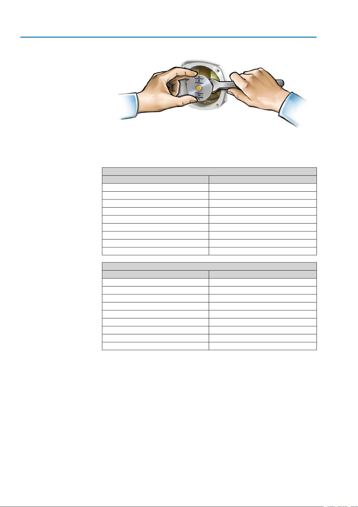
SA 07.2 – SA 16.2 / SAR 07.2 – SAR 16.2 Control unit: electronic (MWG)
Commissioning (basic settings) AC 01.2 Non-Intrusive Modbus TCP/IP
1. Pull off indicator disc. Open end spanner may be used as lever.
2. Refer to table and check if turns/stroke of the actuator correspond to the setting
of the primary reduction gearing (stages 1– 9).
If the setting is wrong: continue with 3.
If the setting is correct: continue with 6.
Control unit MS5.2 (1 to 500 turns per stroke)
Gear stageTurns/stroke above – to
11.0 – 1.9
21.9 – 3.9
33.9 – 7.8
47.8 – 15.6
515.6 – 31.5
631.5 – 62.5
762.5 – 125
8125 – 250
9250 – 500
Control unit MS50.2 (10 to 5,000 turns per stroke)
Gear stageTurns/stroke above – to
110.0 – 19.5
219.5 – 39.0
339.0 – 78.0
478 – 156
5156 – 315
6315 – 625
7625 – 1,250
81,250 – 2,500
92,500 – 5,000
3. Loosen screw [1].
4. Set crown wheel [2] to desired level according to table.
5. Tighten screw [1].
6. Place indicator disc on shaft.
7. Set mechanical position indicator.
52
Page 53
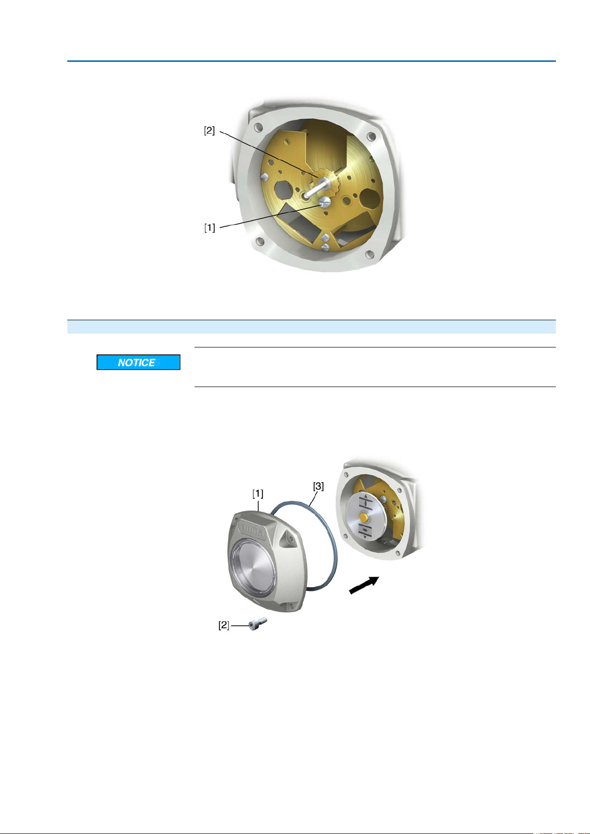
SA 07.2 – SA 16.2 / SAR 07.2 – SAR 16.2 Control unit: electronic (MWG)
AC 01.2 Non-Intrusive Modbus TCP/IP Commissioning (basic settings)
Figure 56: Control unit with reduction gearing
[1] Screw
[2] Crown wheel
9.9. Switch compartment: close
Danger of corrosion due to damage to paint finish!
→
Touch up damage to paint finish after work on the device.
1. Clean sealing faces of housing and cover.
2. Check whether O-ring [3] is in good condition, replace if damaged.
3. Apply a thin film of non-acidic grease (e.g. petroleum jelly) to the O-ring and
insert it correctly.
4. Place cover [1] on switch compartment.
5. Fasten screws [2] evenly crosswise.
53
Page 54
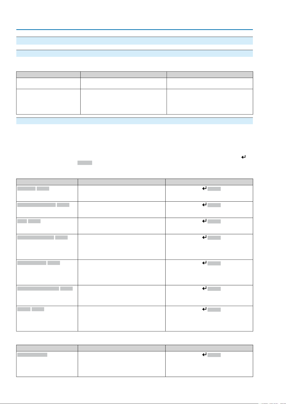
SA 07.2 – SA 16.2 / SAR 07.2 – SAR 16.2 Control unit: electronic (MWG)
Corrective action AC 01.2 Non-Intrusive Modbus TCP/IP
10. Corrective action
10.1. Faults during commissioning
Table 11: Faults during commissioning
RemedyPossible causesFault description
Mechanical position indicator
cannot be set.
Fault in end position
Actuator runs to end stop although the limit switches work
properly.
Reduction gearing is not suitable for
turns/stroke of the actuator.
The overrun was not considered when setting
the limit switching.
The overrun is generated by the inertia of
both the actuator and the valve and the dela y
time of the controls.
10.2. Fault indications and warning indications
Faults interrupt or prevent the electrical actuator operation. In the event of a fault,
the display backlight is red.
Warnings have no influence on the electrical actuator operation.They only serve
for information purposes.
Collective signals include further indications which can be displayed via the
Details push button.
Set gear stage of the reduction gearing.
The control unit might have to be e xchanged.
Determine overrun: Ov errun = trav el cov ered
from switching off until complete standstill.
Set limit switching again considering the
overrun (turn handwheel back by the amount
of the overrun).
Table 12: Faults and warnings via status indications in the display
Warnings S0005
Not ready REMOTE S0006
Fault S0007
Out of specification S0008
Function check S0009
Maintenance required S0010
Failure S0011
Collective signal 02:
Indicates the number of active warnings.
Collective signal 04:
Indicates the number of active signals.
Collective signal 03:
Indicates the number of active faults.
The actuator cannot be operated.
Collective signal 07:
Indication according to NAMUR recommendation NE 107
Actuator is operated outside the normal operation conditions.
Collective signal 08:
Indication according to NAMUR recommendation NE 107
The actuator is being worked on; output signals are temporarily invalid.
Collective signal 09:
Indication according to NAMUR recommendation NE 107
Recommendation to perform maintenance.
Collective signal 10:
Indication according to NAMUR recommendation NE 107
Actuator function failure, output signals are
invalid
For indicated value > 0:Description/causeIndication on display
Press push button Details.
For details, refer to <Warnings and Out of
specification> table.
Press push button Details.
For details, ref er to <Not ready REMOTE and
Function check> table.
Press push button Details to display a list
of detailed indications.
For details, ref er to <Faults and F ailure> tab le.
Press push button Details.
For details refer to <Warnings and Out of
specification> table.
Press push button Details.
For details, ref er to <Not ready REMOTE and
Function check> table.
Press push button Details to display a list
of detailed indications.
Press push button Details to display a list
of detailed indications.
For details, ref er to <Faults and F ailure> tab le.
Table 13: Warnings and Out of specification
Config. warning
54
Collective signal 06:
Possible cause:
Configuration setting is incorrect.
The device can still be operated with restrictions.
RemedyDescription/causeIndication on display
Press push button Details to display a list
of individual indications.
For a description of the individual signals, refer
to Manual (Operation and setting).
Page 55
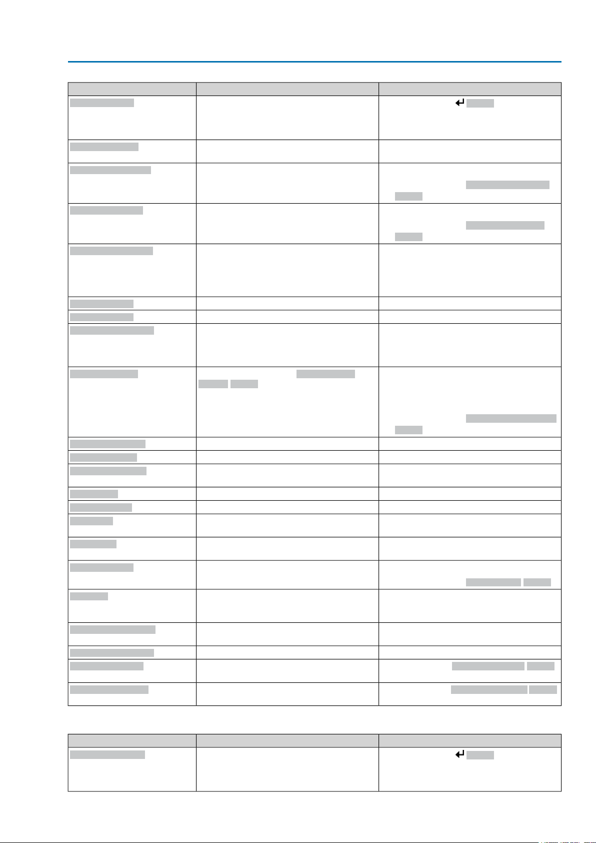
SA 07.2 – SA 16.2 / SAR 07.2 – SAR 16.2 Control unit: electronic (MWG)
AC 01.2 Non-Intrusive Modbus TCP/IP Corrective action
RemedyDescription/causeIndication on display
Internal warning
24 V DC external
Wrn on time running
Wrn on time starts
Failure behav. active
Wrn input AIN 1
Wrn input AIN 2
Wrn setpoint position
Op. time warning
Wrn controls temp.
Wrn motor temp.
Wrn gearbox temp.
RTC not set
RTC button cell
PVST fault
PVST abort
Wrn no reaction
Wrn FOC
Wrn FO cable budget
Wrn FOC connection
Torque wrn OPEN
Torque wrn CLOSE
Collective signal 15:
Device warnings
The device can still be operated with restrictions.
controls has exceeded the power supply limits.
Warning on time max. running time/h ex-
ceeded
Warning on time max. number of motor starts
(starts) exceeded
The failure behaviour is active since all required setpoints and actual values are incorrect.
position
Possible causes:
Input signal for setpoint = 0 (signal loss)
The set time (parameter Perm.op. time,
manual M0570) has been exceeded.The
preset operating time is exceeded for a complete travel from end position OPEN to end
position CLOSED.
high
successfully completed.
or could not be started.
No actuator reaction to operation commands
within the set reaction time.
(no or insufficient Rx receive lev el) or RS-485
format error (incorrect bit(s))
(critical or permissible Rx receive level)
Limit value for torque warning in direction
OPEN exceeded.
Limit value for torque warning in direction
CLOSE exceeded.
Press push button Details to display a list
of individual indications.
For a description of the individual signals, refer
to Manual (Operation and setting).
Check 24 V DC voltage supply.The external 24 V DC voltage supply of the
●
Check modulating behaviour of actuator.
●
Check parameter Perm. running time/h
M0356, re-set if required.
●
Check modulating behaviour of actuator.
●
Check parameter Permissible starts/h
M0357, re-set if required.
Verify signals:
●
Setpoint E1
●
Actual value E2
●
Actual process value E4
Check wiring.Warning: Loss of signal analogue input 1
Check wiring.Warning: Loss of signal analogue input 2
Check setpoint signal.Warning: Loss of signal of actuator setpoint
The warning indications are automatically
cleared once a new operation command is
executed.
●
Check valve.
●
Check parameter Perm.op. time, manual
M0570.
Measure/reduce ambient temperature.Temperature within controls housing too high
Check actuator sizing, correct accordingly.Temperature within motor winding too high
Check actuator sizing, correct accordingly.T emper ature within actuator gear housing too
Set time.Real time clock has not yet been set.
Replace button cell.Voltage of the RTC button cell is too low.
Check actuator (PVST settings).Partial Valve Strok e Test (PVST) could not be
Perform RESET or restart PVST.Partial Valve Strok e Test (PVST) was aborted
●
Check movement at actuator.
●
Check parameter Reaction time M0634.
Check/repair FO cables.Optical receiving signal (channel 1) incorrect
Check/repair FO cables.Warning: FO cable system reserve reached
Fit FO cable connection.W arning FO cable connection is not availab le.
Check parameter Wrn torque OPEN M0768,
re-set if required.
Check parameter Wrn torque CLOSE M0769,
re-set if required.
Table 14: Faults and Failure
Configuration error
Collective signal 11:
Configuration error has occurred.
RemedyDescription/causeIndication on display
Press push button Details to display a list
of individual indications.
For a description of the individual signals, refer
to Manual (Operation and setting).
55
Page 56
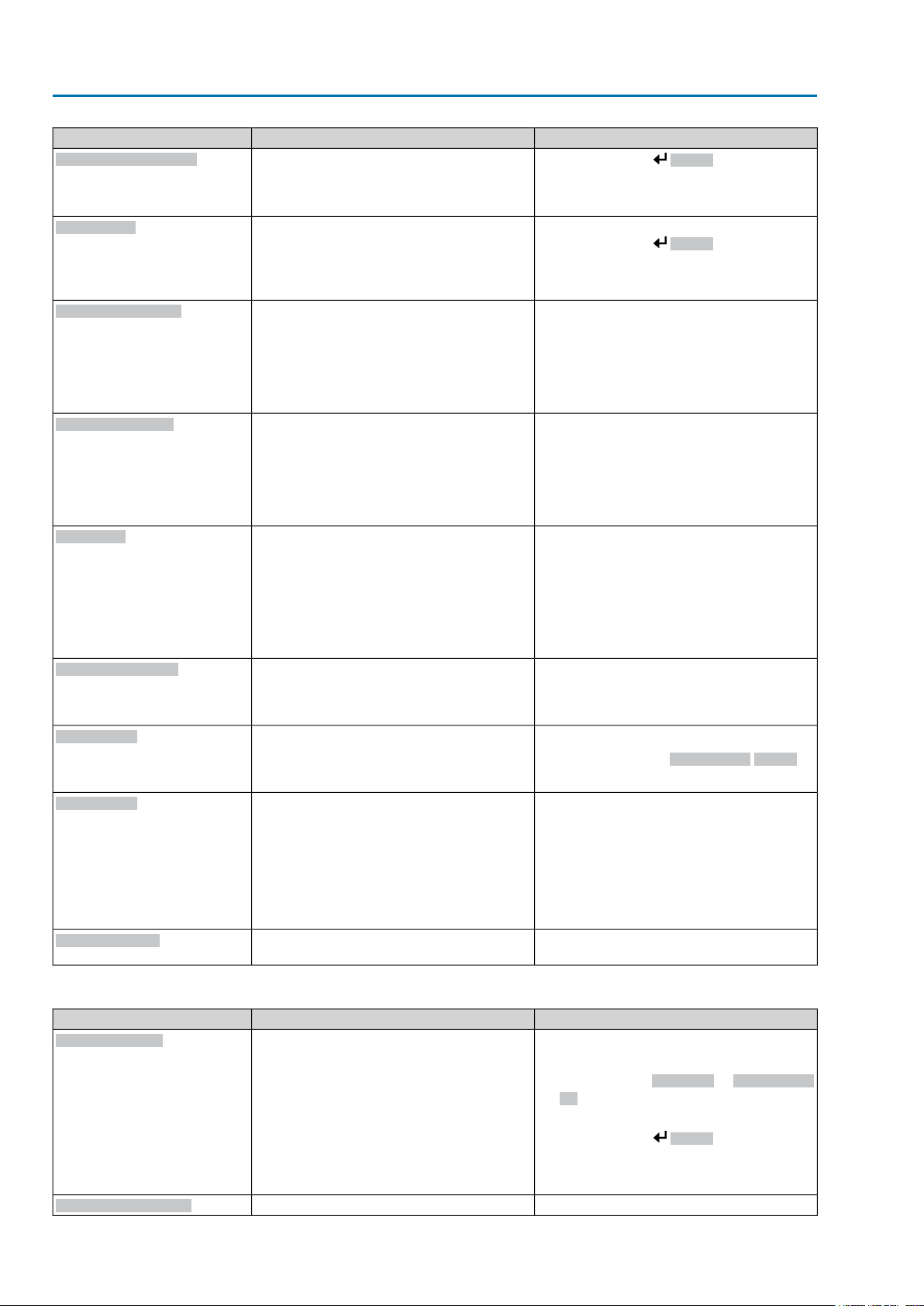
SA 07.2 – SA 16.2 / SAR 07.2 – SAR 16.2 Control unit: electronic (MWG)
Corrective action AC 01.2 Non-Intrusive Modbus TCP/IP
RemedyDescription/causeIndication on display
Config. error REMOTE
Internal error
Torque fault CLOSE
Torque fault OPEN
Phase fault
Incorrect phase seq
Mains quality
Thermal fault
Fault no reaction
Collective signal 22:
Configuration error has occurred.
Collective signal 14:
Internal error has occurred.
Torque fault in direction CLOSE
Torque fault in direction OPEN
●
When connecting to a 3-ph AC system and
with internal 24 V DC supply of the electronics: Phase 2 is missing.
●
When connecting to a 3-ph or 1-ph AC
system and with external 24 V DC supply
of the electronics: One of the phases L1,
L2 or L3 is missing.
The phase conductors L1, L2 and L3 are
connected in the wrong sequence.
Only applicable if connected to a 3-ph AC
system.
Due to insufficient mains quality, the controls
cannot detect the phase sequence (sequence
of phase conductors L1, L2 and L3) within the
pre-set time frame provided for monitoring.
Motor protection tripped
within the set reaction time.
Press push button Details to display a list
of individual indications.
For a description of the individual signals, refer
to Manual (Operation and setting).
AUMA service
Press push button Details to display a list
of individual indications.
For a description of the individual signals, refer
to Manual (Operation and setting).
Perform one of the following measures:
●
Issue operation command in direction
OPEN.
●
Set selector switch to position Local control (LOCAL) and reset fault indication via
push button RESET.
Perform one of the following measures:
●
Issue operation command in direction
CLOSE.
●
Set selector switch to position Local control (LOCAL) and reset fault indication via
push button RESET.
Test/connect phases.
Correct the sequence of the phase conductors
L1, L2 and L3 by exchanging two phases.
●
Check mains voltage.
●
Check parameter Tripping time M0172,
extend time frame if required.
●
Cool down, wait.
●
If the fault indication display persists after
cooling down:
Set selector switch to position Local
-
control (LOCAL) and reset fault indication via push button RESET.
●
Check fuses.
Check movement at actuator.No actuator reaction to operation commands
Table 15: Not ready REMOTE and Function check (collective signal 04)
Wrong oper. cmd
Sel. sw. not REMOTE
56
Collective signal 13:
Possible causes:
●
Several oper ation commands (e.g. OPEN
and CLOSE simultaneously , or OPEN and
SETPOINT operation simultaneously)
●
A setpoint is present and the positioner is
not active
●
For fieldbus: Setpoint exceeds 100.0 %
RemedyDescription/causeIndication on display
●
Check operation commands (send one
operation command only).
●
Set parameter Positioner to Function active.
●
Check setpoint.
Press push button Details to display a list
of individual indications.
For a description of the individual signals, refer
to Manual (Operation and setting).
Set selector switch to position REMOTE.Selector switch is not in position REMOTE.
Page 57
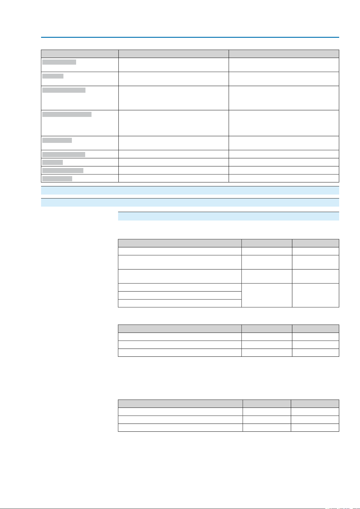
SA 07.2 – SA 16.2 / SAR 07.2 – SAR 16.2 Control unit: electronic (MWG)
AC 01.2 Non-Intrusive Modbus TCP/IP Corrective action
RemedyDescription/causeIndication on display
Service active
Exit service software.Operation via service interface (Bluetooth) and
service software AUMA CDT.
Disabled
Actuator is in operation mode Disabled.
Check setting and status of function <Local
controls enable>.
EMCY stop active
EMCY behav. active
I/O interface
The EMERGENCY stop switch has been operated.The motor control power supply (contactors or thyristors) is disconnected.
Operation mode EMERGENCY is active
(EMERGENCY signal was sent).
0 V are applied at the EMERGENCY input.
●
Enable EMERGENCY stop switch.
●
Reset EMERGENCY stop state by means
of Reset command.
●
Detect cause for EMERGENCY signal.
●
Verify failure source.
●
Apply +24 V DC at EMERGENCY input.
Check I/O interface.The actuator is controlled via the I/O interf ace
(parallel).
Handwheel active
Interlock
Interlock by-pass
PVST active
Start motor operation.Manual operation is activated.
Check interlock signal.An interlock is active.
Check states of main and by-pass valve.By-pass function is interlocked.
Wait until PVST function is complete.Partial Valve Stroke Test (PVST) is active.
10.3. Fuses
10.3.1. Fuses within the actuator controls Fuses used
F1/F2
Primary fuses on power supply unit
Power supply ≤ 500 V
Power supply > 500 V
Thyristor units for motor power up to 3.0 kW
Thyristor units for motor power up to 5.5 kW
Internal 24 V DC supply
F3
Internal 24 V AC supply (115 V AC) for:
F4
●
Heater, switch compartment, reversing contactors control
●
PTC tripping device
●
for 115 V AC also control inputs OPEN - STOP - CLOSE
AUMA art. no.F1/F2G fuse
6.3 x 32 mmSize
K002.2771 A T; 500 VReversing contactors
K002.6652 A FF; 690 VReversing contactors
K002.2771 A T; 500 VThyristor units for motor power up to 1.5 kW
AUMA art. no.F3G fuse according to IEC 60127-2/III
5 x 20 mmSize
K006.1062.0 A T; 250 VVoltage output (power supply unit) = 24 V
K006.1062.0 A T; 250 VVoltage output (power supply unit) = 115 V
5 x 20 mmSize
Automatic reset fuse as short-circuit protection for external 24 V DC supply for
F5
customer (see wiring diagram)
AUMA art. no.F4G-fuse according to IEC 60127-2/III
K001.1841.25 A T; 250 VVoltage output (power supply unit) = 24 V
——Voltage output (power supply unit) = 115 V
57
Page 58
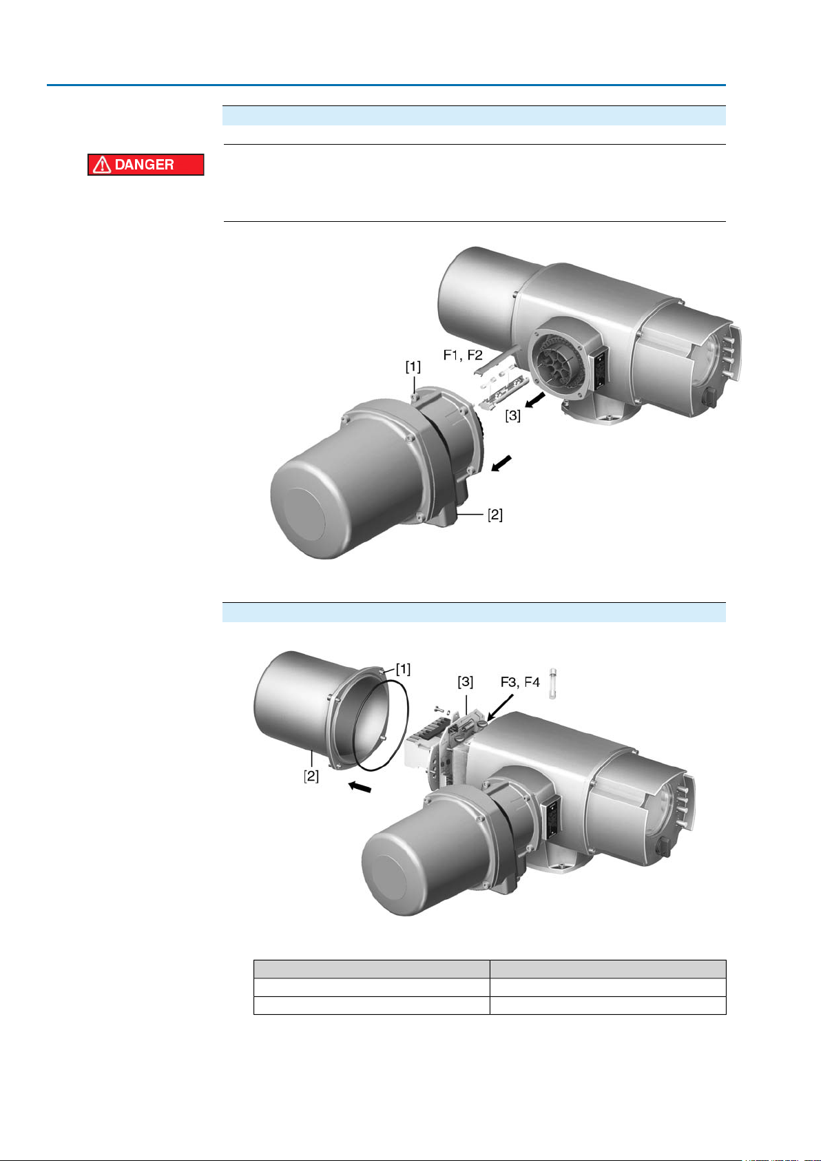
SA 07.2 – SA 16.2 / SAR 07.2 – SAR 16.2 Control unit: electronic (MWG)
Corrective action AC 01.2 Non-Intrusive Modbus TCP/IP
Replace fuses F1/F2
Hazardous voltage!
Risk of electric shock.
→
Disconnect device from the mains before opening.
1. Loosen screws [1] and remove plug/socket connector [2].
2. Pull fuse holder [3] out of pin carrier, open fuse cover and replace old fuses by
new ones.
Test/replace fuses F3/F4
1. Loosen screws [1] and remove cover [2] on the rear of the actuator controls.
The power supply unit has measurement points (solder pins) allowing to perf orm
a resistance (continuity) measurement:
Measuring pointsVerifying
MTP5 – MTP6F3
MTP7 – MTP8F4
2. T o replace def ectiv e fuses:. Carefully loosen power supply unit [3] and pull out.
(The fuses are on the equipped part of the power supply board).
58
Page 59
SA 07.2 – SA 16.2 / SAR 07.2 – SAR 16.2 Control unit: electronic (MWG)
AC 01.2 Non-Intrusive Modbus TCP/IP Corrective action
Cable damage due to pinching!
Risk of functional failures.
→
Carefully assemble power supply unit to avoid pinching the cables.
10.3.2. Motor protection (thermal monitoring)
In order to protect against overheating and impermissibly high surface temper atures
at the actuator, PTC thermistors or thermoswitches are embedded in the motor
winding.The thermoswitch is tripped as soon as the max. permissible winding
temperature has been reached.
The actuator is switched off and the following signals are given:
●
LED 3 (thermal fault) on the local controls is illuminated.
●
Status indication S0007 displays a fault.The fault Thermoswitch is displayed
when selecting Details.
The motor has to cool down before the operation can be resumed. Depending on
the parameter setting, the fault signal is either automatically reset or the f ault signal
has to be acknowledged.
The acknowledgement is made:
●
via the push button Reset in selector switch position LOCAL.
●
or with the reset command via fieldbus.
For further information to this topic, please refer to Manual (Operation and setting).
59
Page 60
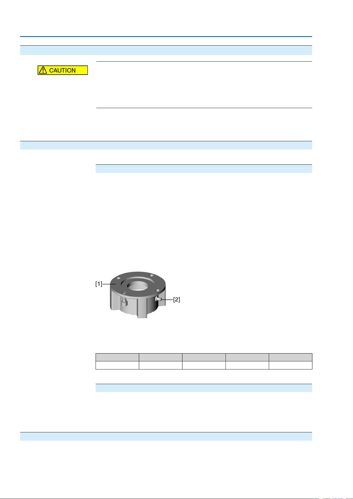
SA 07.2 – SA 16.2 / SAR 07.2 – SAR 16.2 Control unit: electronic (MWG)
Servicing and maintenance AC 01.2 Non-Intrusive Modbus TCP/IP
11. Servicing and maintenance
Damage caused by inappropriate maintenance!
→
Servicing and maintenance must be carried out exclusively by suitably qualified
personnel having been authorised by the end user or the contractor of the plant.
Therefore, we recommend contacting our service.
→
Only perform servicing and maintenance tasks when the device is switched off.
AUMA
Service & Support
AUMA off er extensiv e service such as servicing and maintenance as well as customer
product training. For the relevant contact addresses, please refer to <Addresses>
in this document or to the Internet (www.auma.com).
11.1. Preventive measures for servicing and safe operation
The following measures are required to ensure safe device operation:
6 months after commissioning and then every year
●
Carry out visual inspection:
Cable entries, cable glands, b lanking plugs, etc. have to be checked for correct
tightness and sealing.
Respect torques according to manufacturer's details.
●
Check fastening screws between actuator and gearbox/valve for tightness. If
required, fasten screws while applying the tightening torques as indicated in
chapter <Assembly>.
●
When rarely operated: Perform test run.
●
For devices with output driv e A: Press in Lithium soap EP m ulti-purpose grease
on mineral oil base at the grease nipple with a grease gun.
●
Lubrication of the valve stem must be done separately.
Figure 57: Output drive type A
11.2. Maintenance Lubrication
60
[1] Output drive type A
[2] Grease nipple
Table 16: Grease quantities for bearing of output drive type A
A 16.2A 14.2A 10.2A 07.2Output drive
1)
For grease at density r = 0.9 kg/dm³1)
5321.5Quantity [g]
For enclosure protection IP68
After continuous immersion:
●
Check actuator.
●
In case of ingress of water, locate leaks and repair, dry device correctly and
check for proper function.
●
In the factory, the gear housing is filled with grease.
Page 61

SA 07.2 – SA 16.2 / SAR 07.2 – SAR 16.2 Control unit: electronic (MWG)
AC 01.2 Non-Intrusive Modbus TCP/IP Servicing and maintenance
●
Grease change is performed during maintenance
- Generally after 4 to 6 years for modulating duty.
- Generally after 6 to 8 years if operated frequently (open-close duty).
- Generally after 10 to 12 years if operated rarely (open-close duty).
●
We recommend exchanging the seals when changing the grease.
●
No additional lubrication of the gear housing is required during operation.
11.3. Disposal and recycling
Our devices have a long lifetime. However, they have to be replaced at one point in
time.The devices have a modular design and may, therefore, easily be separated
and sorted according to materials used, i.e.:
●
electronic scrap
●
various metals
●
plastics
●
greases and oils
The following generally applies:
●
Greases and oils are hazardous to water and must not be released into the
environment.
●
Arrange for controlled waste disposal of the disassembled material or for separate recycling according to materials.
●
Observe the national regulations for waste disposal.
61
Page 62
SA 07.2 – SA 16.2 / SAR 07.2 – SAR 16.2 Control unit: electronic (MWG)
Technical data AC 01.2 Non-Intrusive Modbus TCP/IP
12. Technical data
Information The following technical data includes standard and optional features. For detailed
information on the customer-specific version, refer to the order-related data sheet.
The technical data sheet can be downloaded from the Internet at www.auma.com
in both German and English (please state the order number).
12.1. Technical data Multi-turn actuators
Features and functions
Short-time duty S2 - 15 min (multi-turn actuators for open-close duty)
Intermittent duty S4 - 25 % (multi-turn actuators for modulating duty)
Short-time duty S2 - 30 min (multi-turn actuators for open-close duty)
Intermittent duty S4 - 50 % (multi-turn actuators for modulating duty)
Intermittent duty S5 - 25 % (multi-turn actuators for modulating duty)
S5 - 25 % only in combination with insulation class H
3-ph AC asynchronous motor, type IM B9 according to IEC 60034Standard:Motors
1-phase AC motor, type IM B9 according to IEC 60034
DC shunt motor, type IM B14 according to IEC 60034
DC compound motor, type IM B14 according to IEC 60034
F, tropicalizedStandard:Insulation class
H, tropicalizedOption:
3-phase and 1-phase AC motors:Thermoswitches (NC)
DC motors:Without
PTC thermistors (according to DIN 44082)Option:
110 – 120 V AC, 220 – 240 V AC or 400 V AC (externally supplied)Voltages:Motor heater (option)
Handwheel lockable
Handwheel stem extension
Power tool for emergency operation with square 30 mm or 50 mm
B1 according to EN ISO 5210Standard:Valve attachment
A, B2, B3, B4 according to EN ISO 5210
A, B, D, E according to DIN 3210
C according to DIN 3338
Mains voltage, mains frequency
Self-locking
Manual operation
Indication for manual operation
(option)
Standard:Type of duty
Option:
For nominal voltage and 40 °C ambient temperature and at average load with 35 % of the
max. torque
Option:
Refer to motor name plate
Permissible variation of mains voltage: ±10 %
Permissible variation of mains frequency: ±5 % (for 3-phase AC and 1-phase AC current)
Category III according to IEC 60364-4-443Overvoltage category
Standard:Motor protection
Self-locking: Output speeds up to 90 rpm (50 Hz), 108 rpm (60 Hz)
NOT self-locking: Output speeds up to 125 rpm (50 Hz), 150 rpm (60 Hz)
Multi-turn actuators are self-locking, if the valve position cannot be changed from standstill
while torque acts upon the output drive.
Power depending on the size 12.5 – 25 W
Manual drive for setting and emergency operation, handwheel does not rotate during elec-
trical operation.
Option:
Indication whether manual operation is active/not active via single switch (1 change-over
contact)
Option:
Special output drive types: AF, AK, AG, B3D, ED, DD, IB1, IB3
A prepared for permanent lubrication of stem
62
Page 63
SA 07.2 – SA 16.2 / SAR 07.2 – SAR 16.2 Control unit: electronic (MWG)
AC 01.2 Non-Intrusive Modbus TCP/IP Technical data
Electronic control unit (only in combination with AC actuator controls)
Non-intrusive setting (option)
(option)
Technical data for handwheel activation switches
Silver plated contacts:
Service conditions
Installation altitude
to EN 60529
Vibration resistance according
to IEC 60068-2-6
Finish coating
Lifetime
Magnetic limit and torque transmitter (MWG)
For 1 to 500 turns/stroke or
10 to 000 turns per stroke
Via actuator controlsPosition feedback signal
Via actuator controlsTorque feedback signal
Continuous indication, adjustable indicator disc with symbols OPEN and CLOSEDMechanical position indicator
Blinking signal via actuator controlsRunning indication
Resistance type heater with 5 W, 24 V ACHeater in switch compartment
106 startsMechanical lifetime
12 V DCU min.
250 V ACU max.
3 A at 250 V (inductive load, cos phi = 0.8)I max. AC current
3 A at 12 V (resistive load)I max. DC current
Indoor and outdoor use permissibleUse
Any positionMounting position
≤ 2 000 m above sea level
> 2,000 m above sea level, on request
Standard:Ambient temperature
–60 °C to +60 °C (3-phase AC motors)Options:
For exact version, refer to actuator name plate.
Standard:Enclosure protection according
IP68
For special motors differing enclosure protection: refer to name plate.
DS Terminal compartment additionally sealed against interior (double sealed)Option:
According to AUMA definition, enclosure protection IP68 meets the following requirements:
●
Depth of water: Maximum 8 m head of water
●
Duration of continuous immersion in water: Maximum 96 hours
●
Up to 10 operations during flooding.
Modulating duty is not possible during continuous immersion.
For actual version, refer to actuator name plate.
Pollution degree 4 (when closed) according to EN 50178Pollution degree
2 g, from 10 to 200 Hz
Resistant to vibration during start-up or for failures of the plant. However, a fatigue strength
may not be derived from this.Valid for multi-turn actuators in version AUMA NORM (with
AUMA plug/socket connector, without actuator controls). Not valid in combination with
gearboxes.
Standard:Corrosion protection
KS: Suitable for installation in industrial units, in water or power plants with a
low pollutant concentration as well as for installation in occasionally or permanently aggressive atmosphere with a moderate pollutant concentration (e.g.
wastewater treatments plants, chemical industry)
Option:
KX: Suitable for installation in extremely aggressive atmospheres with high humidity and high pollutant concentration
KX-G : same as KX, however aluminium-free version (outer parts)
Powder coating
Two-component iron-mica combination
AUMA silver-grey (similar to RAL 7037)Standard:Colour
Other colours are possible on request.Option:
AUMA multi-turn actuators meet or exceed the lifetime requirements of EN 15714-2. For
further details, please contact AUMA
63
Page 64
SA 07.2 – SA 16.2 / SAR 07.2 – SAR 16.2 Control unit: electronic (MWG)
Technical data AC 01.2 Non-Intrusive Modbus TCP/IP
Further information
EU Directives
Electromagnetic Compatibility (EMC): (2004/108/EC)
Low Voltage Directive: (2006/95/EC)
Machinery Directive: (2006/42/EC)
12.2. Technical data Actuator controls
Features and functions
Power supply
Mains frequency
External supply of the electronics (option)
Current consumption
Modbus TCP/IP interface with
additional input signals (options)
the optional additional inputs
Refer to name plates at controls and motor
Permissible variation of mains voltage: ±10 %
Permissible variation of mains voltage: ±30 % (option)
Permissible variation of mains frequency: ±5 %
24 V DC +20 % / –15 %
Current consumption: Basic version approx. 250 mA, with options up to 500 mA
The external power supply must have a reinforced insulation against the mains voltage in
accordance with IEC 61010-1 and may only be supplied by a circuit limited to 150 VA in accordance with IEC 61010-1.
Current consumption of the controls depending on mains voltage:
For permissible variation of mains voltage of ±10 %:
●
100 to 120 V AC = max. 740 mA
●
208 to 240 V AC = max. 400 mA
●
380 to 500 V AC = max. 250 mA
●
515 to 690 V AC = max. 200 mA
For permissible variation of mains voltage of ±30 %:
●
100 to 120 V AC = max. 1,200 mA
●
208 to 240 V AC = max. 750 mA
●
380 to 500 V AC = max. 400 mA
●
515 to 690 V AC = max. 400 mA
Category III according to IEC 60364-4-443Overvoltage category
The controls are designed for the rated motor power, refer to motor name plateRated power
Standard:Switchgear
Reversing contactors (mechanically and electrically interlocked) f or A UMA power
classes A1/A2
Options:
Reversing contactors (mechanically and electrically interlocked) f or A UMA power
class A3
Thyristor unit for mains voltage up to 500 V AC (recommended for modulating
actuators) for AUMA power classes B1, B2 and B3
Reversing contactors are designed f or a lif etime of 2 million starts. For applications requiring
a high number of starts, we recommend using thyristor units.
For the assignment of AUMA power classes, please refer to electrical data on actuator.
Via Modbus TCP/IP interfaceControl and feedback signals
●
2 free analogue inputs (0/4 – 20 mA), 4 free digital inputs
Signal transmission is made via Modbus TCP/IP interface
-
●
OPEN, STOP, CLOSE, EMERGENCY inputs, I/O interface with 0/4 – 20 mA input for
position setpoint
OPEN, STOP, CLOSE, EMERGENCY control inputs
-
I/O interface for selecting the control type (Modb us TCP/IP or additional binary OPEN,
-
STOP, CLOSE input signals)
MODE for selecting between OPEN - CLOSE control and setpoint control (0/4 – 20
-
mA)
24 V DC, current consumption: approx. 10 mA per inputStandardVoltage and current values of
Options:
48 V DC, current consumption: approx. 7 mA per input
60 V DC, current consumption: approx. 9 mA per input
115 V DC, current consumption: approx. 15 mA per input
115 V AC, current consumption: approx. 15 mA per input
All input signals must be supplied with the same potential.
Via Modbus TCP/IP interfaceStatus signals
64
Page 65

SA 07.2 – SA 16.2 / SAR 07.2 – SAR 16.2 Control unit: electronic (MWG)
AC 01.2 Non-Intrusive Modbus TCP/IP Technical data
Features and functions
Modbus TCP/IP interface with
additional output signals (options)
Bluetooth
Communication interface
Additional output signals (only available in combination with additional input signals)
Binary output signals
●
6 programmable output contacts:
5 potential-free NO contacts with one common, max. 250 V AC, 1 A (resistive load)
-
Standard assignment: End position CLOSED, end position OPEN, selector switch
REMOTE, torque fault CLOSE, torque fault OPEN
1 potential-free change-over contact, max. 250 V AC, 5 A (resistive load)
-
Standard assignment: Collectiv e fault signal (torque fault, phase f ailure, motor protection tripped)
●
6 programmable output contacts:
5 change-over contacts with one common, max. 250 V AC, 1 A (resistive load)
-
1 potential-free change-over contact, max. 250 V AC, 5 A (resistive load)
-
●
6 programmable output contacts:
6 potential-free change-over contacts without one common, per contact max. 250 V
-
AC, 5 A (resistive load)
All binary output signals must be supplied with the same potential.
Analogue output signal for position feedback
●
Galvanically isolated position feedback E2 = 0/4 – 20 mA (load max. 500 Ω)
Standard:Local controls
●
Selector switch LOCAL - OFF - REMOTE (lockable in all three positions)
●
Push buttons OPEN, STOP, CLOSE, RESET
Local STOP
-
The actuator can be stopped via push button Stop of local controls if the
selector switch is in position REMOTE. Not activated when leaving the
factory.
●
6 indication lights:
End position and running indication CLOSED (yellow), torque fault CLOSE
-
(red), motor protection tripped (red), torque fault OPEN (red), end position
and running indication OPEN (green), Bluetooth (blue)
●
Graphic LC display, illuminated
Options:
●
Special colours for the 5 indication lights:
End position CLOSED (green), torque fault CLOSE (blue), torque fault
-
OPEN (yellow), motor protection tripped (violet), end position OPEN (red)
Bluetooth class II chip, version 2.0 with a range up to 10 m in industrial en vironments. Supports
the SPP Bluetooth profile (Serial Port Profile).
Programming software:
AUMA CDT, commissioning and diagnostic tool for windows based PCs, PDAs and smart
phones
Standard:Application functions
●
Switch-off mode adjustable
Limit or torque seating for end positions OPEN and CLOSED
-
●
Torque by-pass, adjustable up to 5 seconds (no torque monitoring during
start-up time)
●
Start and end of stepping mode as well as ON and OFF times (1 to 1,800
seconds) can be set individually for directions OPEN and CLOSE.
●
Any 8 intermediate positions between 0 and 100 %, reaction and signal behaviour programmable
●
Positioner
Position setpoint via Modbus TCP/IP interface
-
Automatic adaptation of dead band (adaptive behaviour selectable)
-
Change-over between OPEN - CLOSE control and setpoint control via
-
Modbus TCP/IP interface
Option:
●
PID controller with adaptive positioner , 0/4 – 20 mA inputs for process setpoint
and actual process value
65
Page 66
SA 07.2 – SA 16.2 / SAR 07.2 – SAR 16.2 Control unit: electronic (MWG)
Technical data AC 01.2 Non-Intrusive Modbus TCP/IP
Features and functions
Safety functions (options)
Monitoring functions
Diagnostic functions
●
EMERGENCY operation, behaviour programmable
Digital input low active
-
Reaction can be selected: Stop, run to end position CLOSED, run to end position
-
OPEN, run to intermediate position
Torque monitoring can be by-passed during EMERGENCY operation.
-
Thermal protection can be by-passed during EMERGENCY operation (only in com-
-
bination with thermoswitch within actuator, not with PTC thermistor).
●
Enabling the local controls via Modbus TCP/IP interface.Thus, actuator operation can
be enabled or disabled via push buttons on the local controls.
●
Local STOP
The actuator can be stopped via push button Stop of local controls if the selector
-
switch is in position REMOTE. Not activated when leaving the factory.
●
EMERGENCY Stop push button (latching) interrupts electrical operation, irrespective of
the selector switch position
●
Interlock, enabling the operation commands OPEN or CLOSE via Modbus TCP/IP interface
●
Valve overload protection (adjustable), results in switching off and generates fault signal
●
Motor temperature monitoring (thermal monitoring), results in switching off and generates
fault indication
●
Monitoring the heater within actuator, generates warning signal
●
Monitoring of permissible on-time and number of starts (adjustable), generates warning
signal
●
Operation time monitoring (adjustable), generates warning signal
●
Phase failure monitoring, results in switching off and generates fault signal
●
Automatic correction of rotation direction upon wrong phase sequence (3-ph AC current)
●
Electronic device ID with order and product data
●
Operating data logging: A resettable counter and a lifetime counter each for:
Motor running time, number of starts, torque switch trippings in end position CLOSED,
-
limit switch trippings in end position CLOSED , torque switch trippings in end position
OPEN, limit switch trippings in end position OPEN, torque faults CLOSE, torque f aults
OPEN, motor protection trippings
●
Time-stamped event report with history for setting, operation and faults:
Status signals according to NAMUR recommendation NE 107: "Failure", "Function
-
check", "Out of specification", "Maintenance required"
●
Torque characteristics (for version with MWG in actuator)
3 torque characteristics (torque-travel characteristic) f or opening and closing directions
-
can be saved separately. Torque characteristics stored can be shown on the display.
Standard:Motor protection evaluation
Monitoring the motor temperature in combination with thermoswitches within
actuator motor
Options:
Additional thermal overload relay in controls combined with thermoswitches
within actuator
PTC tripping device in combination with PTC thermistors within actuator motor
AUMA plug/socket connector with screw-type connectionStandard:Electrical connection
Options:
●
Terminals or crimp connection
●
Gold-plated control contacts (pins and sockets)
Metric threadsStandard:Threads for cable entries
Pg-threads, NPT-threads, G-threadsOptions:
Refer to name plateWiring diagram
Further options for Non-intrusive version with MWG in the actuator
Setting of limit and torque switching via local controls
Torque feedback signal
Via Modbus TCP/IP interface
Galvanically isolated analogue output 0/4 – 20 mA (load max. 500 Ω), only possible in com-
bination with output contact
66
Page 67
SA 07.2 – SA 16.2 / SAR 07.2 – SAR 16.2 Control unit: electronic (MWG)
AC 01.2 Non-Intrusive Modbus TCP/IP Technical data
Settings/programming the Modbus TCP/IP interface
Baud rate, parity and Modbus address are set via the display of the AC 01.2Setting the Modbus interface
Setting the Modbus gateway
Commands and signals of the Modbus TCP/IP interface
Process representation output
(command signals)
Process representation input
(feedback signals)
Process representation input
(fault signals)
Behaviour on loss of communication
Settings are made via web server
Standard settings of the IP interface:
IP Address Selection
Static IPAddress Type
192.168.255.1Static IP Address
255.255.0.0Subnet Mask
192.168.0.1Default Gateway
OPEN, STOP, CLOSE, position setpoint, RESET , EMERGENCY oper ation command, enable
LOCAL, Interlock OPEN/CLOSE
●
End positions OPEN, CLOSED
●
Actual position value
●
Actual torque value, requires magnetic limit and torque transmitter (MWG) in actuator
●
Selector switch in position LOCAL/REMOTE
●
Running indication (directional)
●
Torque switches OPEN, CLOSED
●
Limit switches OPEN, CLOSED
●
Manual operation by handwheel or via local controls
●
Analogue (2) and digital (4) customer inputs
●
Motor protection tripped
●
Torque switch tripped in mid-travel
●
One phase missing
●
Failure of analogue customer inputs
The behaviour of the actuator is programmable:
●
Stop in current position
●
Travel to end position OPEN or CLOSED
●
Travel to any intermediate position
●
Execute last received operation command
67
Page 68
SA 07.2 – SA 16.2 / SAR 07.2 – SAR 16.2 Control unit: electronic (MWG)
Technical data AC 01.2 Non-Intrusive Modbus TCP/IP
General Modbus TCP/IP data
Modbus TCP/IP according to IEC 61158 and IEC 61784Communication protocol
Star topology/ point-to-point topologyNetwork topology
Transmission medium
Transmission rate/cable length
Supported fieldbus functions
IEC IEEE 802.3, cable recommendation: Cat. 6
●
Baud rate: 10/100 Mbit/s
●
Maximum cable length: 100 m
A
Polling between master and slaves (query response).Fieldbus access
01 Read Coil Status
02 Read Input Status
03 Read Holding Registers
04 Read Input Registers
05 Force Single Coil
15 (0FHex) Force Multiple Coils
06 Preset Single Register
16 (10Hex) Preset Multiple Registers
17 (11Hex) Report Slave ID
08 Diagnostics:
●
00 00 Loopback
●
00 10 (0AHex) Clear Counters and Diagnostic Register
●
00 11 (0BHex) Return Bus Message Count
●
00 12 (0CHex) Return Bus Communication Error Count
●
00 13 (0DHex) Return Bus Exception Error Count
●
00 14 (0EHex) Return Slave Message Count
●
00 15 (0FHex) Return Slave No Response Count
●
00 16 (10Hex) Return Slave NAK Count
●
00 17 (11Hex) Return Slave Busy Count
●
00 18 (12Hex) Return Character Overrun Count
Service conditions
Installation altitude
to EN 60529
EN 60664-1 (VDE 0110-1)
Vibration resistance according
to IEC 60068-2-6
Indoor and outdoor use permissibleUse
Any positionMounting position
≤ 2 000 m above sea level
> 2,000 m above sea level, on request
–25 °C to +70 °CStandard:Ambient temperature
For exact version, refer to actuator controls name plate.
Up to 100 % relative humidity across the entire permissible temperature rangeHumidity
Standard:Enclosure protection according
IP68 with AUMA 3-phase AC motor/1-phase AC motor
For special motors differing enclosure protection: refer to name plate.
DS Terminal compartment additionally sealed against interior (double sealed)Option:
According to AUMA definition, enclosure protection IP68 meets the following requirements:
●
Depth of water: Maximum 8 m head of water
●
Duration of continuous immersion in water: Maximum 96 hours
●
Up to 10 operations during continuous immersion
Modulating duty is not possible during continuous immersion.
For exact version, refer to actuator controls name plate.
Pollution degree 4 (when closed)Pollution degree according to
1 g, from 10 Hz to 200 Hz
Resistant to vibration during start-up or for failures of the plant. However, a fatigue strength
may not be derived from this. Not valid in combination with gearboxes.
Standard:Corrosion protection
KS: Suitable f or use in areas with high salinity, almost permanent condensation,
and high pollution.
Option:
KX: Suitable f or use in areas with extremely high salinity, permanent condensation, and high pollution.
68
Page 69
SA 07.2 – SA 16.2 / SAR 07.2 – SAR 16.2 Control unit: electronic (MWG)
AC 01.2 Non-Intrusive Modbus TCP/IP Technical data
Service conditions
Finish coating
Accessories
Wall bracket
Further information
EU Directives
Powder coating
Two-component iron-mica combination
AUMA silver-grey (similar to RAL 7037)Standard:Colour
Available colours on request.Option:
AC 01.2 mounted separately from the actuator , including plug/soc ket connector. Connecting
cable on request.
Recommended for high ambient temperatures, difficult access, or in case of hea vy vibr ation
during service.
Cable length between actuator and AC 01.2 max. 100 m. Not suitab le f or v ersion with potentiometer in the actuator. Instead of the potentiometer, the actuator has to be equipped with
an electronic position transmitter. Cable length for non-intrusive version with MWG in the
actuator max. 100 m. Requires separate data cable for MWG.
AUMA CDTProgramming software for PC
Approx. 7 kg (with AUMA plug/socket connector)Weight
Electromagnetic Compatibility (EMC): (2004/108/EC)
Low Voltage Directive: (2006/95/EC)
Machinery Directive: (2006/42/EC)
69
Page 70
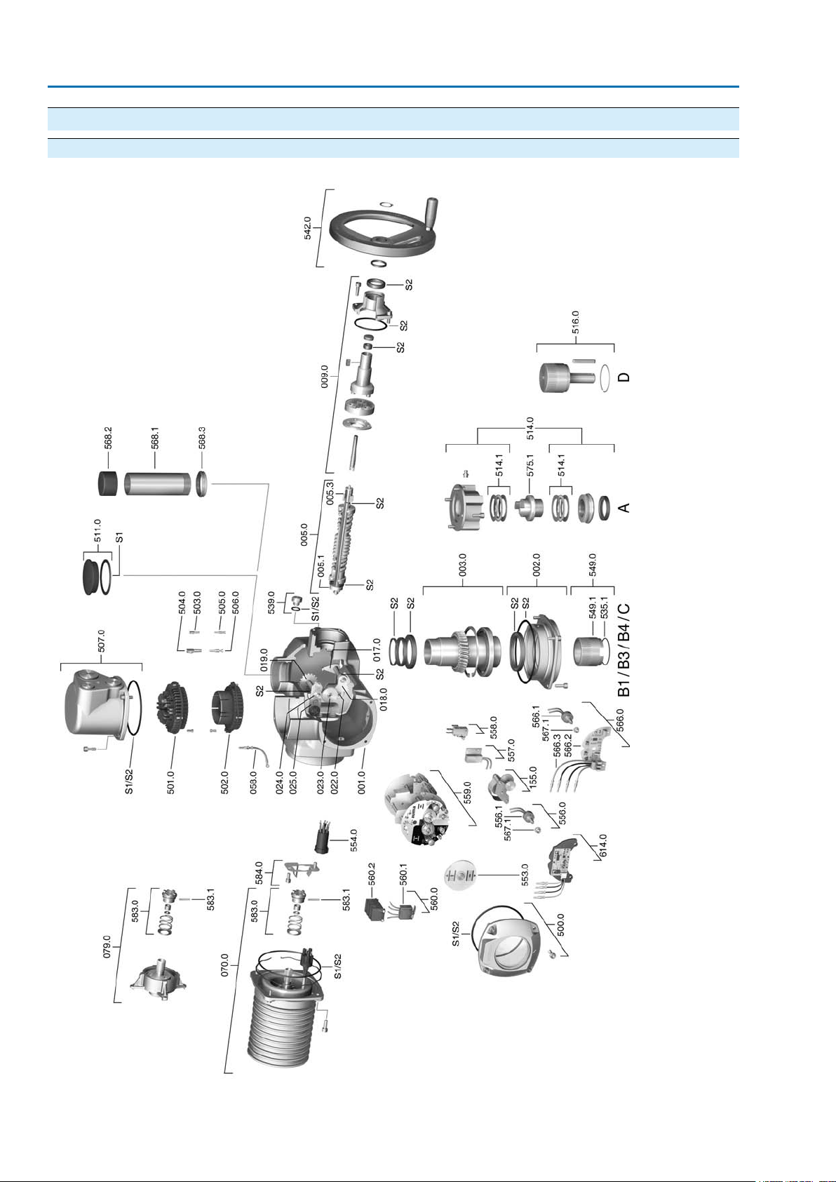
SA 07.2 – SA 16.2 / SAR 07.2 – SAR 16.2 Control unit: electronic (MWG)
Spare parts AC 01.2 Non-Intrusive Modbus TCP/IP
13. Spare parts
13.1. Spare parts list SA 07.2 – SA 16.2/SAR 07.2 – SAR 16.2
70
Page 71
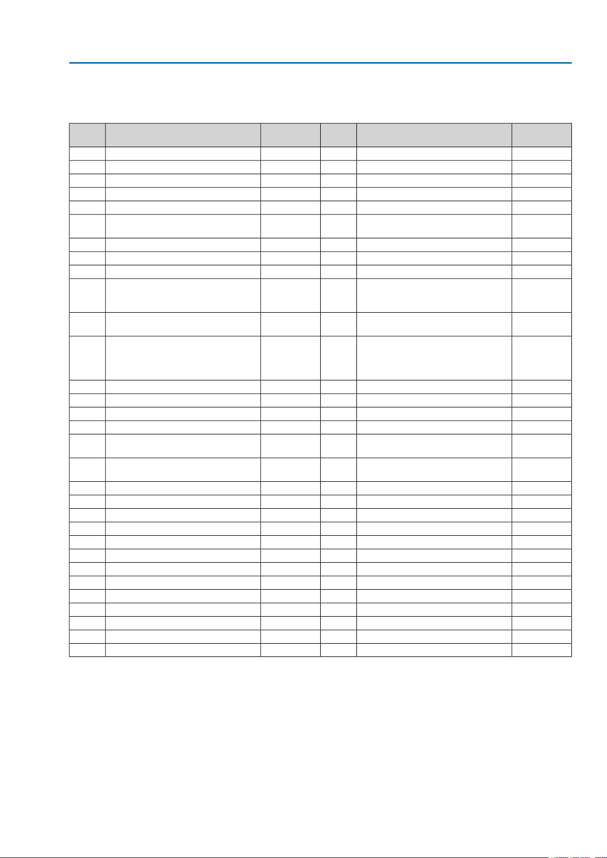
SA 07.2 – SA 16.2 / SAR 07.2 – SAR 16.2 Control unit: electronic (MWG)
AC 01.2 Non-Intrusive Modbus TCP/IP Spare parts
Information: Please state device type and our order number (see name plate) when ordering spare parts. Only
original AUMA spare parts should be used. Failure to use original spare parts voids the warranty and exempts
AUMA from any liability. Delivered spare parts may slightly vary from the representation in these instructions.
No.
Planetary gear for motor drive
(SA/SAR 07.2 - 16.2 for VD motor)079.0
TypeDesignationRef.
No.
Socket carrier for motor plug/socket
connector with cable harness554.0Manual drive coupling005.3
Blinker transmitter including pins at
wires (without impulse disc and insulation plate558.0Crown wheel019.0
Control unit with torque switching
heads and switches559.0-1Sub-assemblyDrive pinion II for torque switching022.0
Control unit with magnetic limit and
torque transmitter (MWG) for Non-intrusive version in combination with
AUMATIC integral controls559.0-2Sub-assemb lyOutput drive wheel for limit switching023.0
Switch case560.2Sub-assemblyMotor (VD motor incl. ref.no. 079.0)070.0
Potentiometer for RWG without slip
clutch566.1Sub-assemblyReduction gearing155.0
Stem protection tube (without cap)568.1Sub-assemblySocket for controls503.0
Cap for stem protection tube568.2Sub-assemblySocket for motor504.0
V-seal568.3Sub-assemblyPin for controls505.0
Stem nut A (without thread)575.1Sub-assemb lyPin for motor506.0
Pin for motor coupling583.1Sub-assemb lyThreaded plug511.0
TypeDesignationRef.
Sub-assemblyScrew plug539.0Sub-assemblyHousing001.0
Sub-assemblyHandwheel with ball handle542.0Sub-assemblyBearing flange002.0
Sub-assemblyOutput drive B1/B3/B4/C549.0Sub-assemblyHollow shaft003.0
Sub-assemblyOutput drive sleeve B1/B3/B4/C549.1Sub-assemblyDrive shaft005.0
Sub-assemblyMechanical position indicator553.0Motor coupling005.1
Sub-assembly
Sub-assemblyPotentiometer as position transmitter556.0Sub-assemblyManual gearing009.0
Sub-assemblyPotentiometer without slip clutch556.1Sub-assemblyTorque lever017.0
Sub-assemblyHeater557.0Gear segment018.0
Sub-assembly
Sub-assembly
Sub-assembly
Sub-assemblySwitch stack for direction OPEN560.0-1Sub-assemblyDrive wheel for limit switching024.0
Sub-assemblySwitch stack for direction CLOSE560.0-2Sub-assemblyLocking plate025.0
Sub-assemblySwitch for limit/torque switching560.1Sub-assemblyWire for protective earth058.0
Sub-assemblyPosition transmitter RWG566.0Sub-assembly
Sub-assembly
Sub-assemblyPosition transmitter board for RWG566.2Sub-assemblyCover500.0
Sub-assemblyWire harness for RWG566.3Sub-assemblySocket carrier (complete with sockets)501.0
Sub-assemblySlip clutch for potentiometer567.1Sub-assemblyPin carrier without pins502.0
Sub-assemblyMotor coupling on motor shaft583.0Sub-assemb lyCover for electrical connection507.0
Sub-assemblyRetaining spring for motor coupling584.0Sub-assemblyOutput drive form A (without stem nut)514.0
Sub-assemblyPosition transmitter EWG614.0Sub-assemblyAxial needle roller bearing514.1
SetSeal kit, smallS1Sub-assemblyOutput drive D516.0
SetSeal kit, largeS2Snap ring535.1
71
Page 72
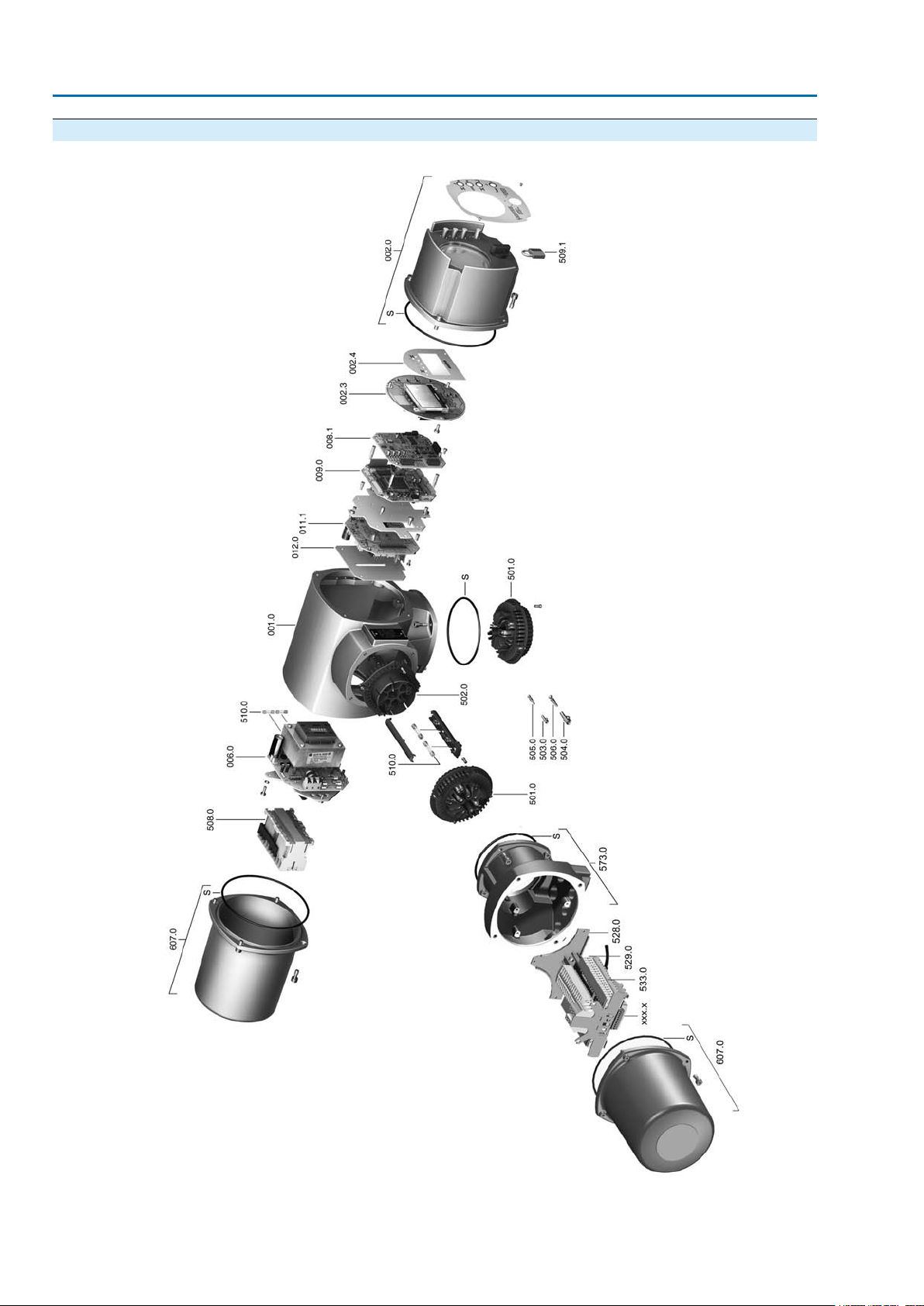
SA 07.2 – SA 16.2 / SAR 07.2 – SAR 16.2 Control unit: electronic (MWG)
Spare parts AC 01.2 Non-Intrusive Modbus TCP/IP
13.2. AUMATIC AC 01.2 actuator controls with AUMA plug/socket connector (SFH)
72
Page 73

SA 07.2 – SA 16.2 / SAR 07.2 – SAR 16.2 Control unit: electronic (MWG)
AC 01.2 Non-Intrusive Modbus TCP/IP Spare parts
Information: Please state device type and our order number (see name plate) when ordering spare parts. Only
original AUMA spare parts should be used. Failure to use original spare parts voids the warranty and exempts
AUMA from any liability. Delivered spare parts may slightly vary from the representation in these instructions.
no.
TypeDesignationRef.
Sub-assemblyHousing001.0
Sub-assemblyLocal controls002.0
Sub-assemblyLocal controls board002.3
Face plate for display002.4
Sub-assemblyPower supply unit006.0
Fieldbus board008.1
Sub-assemblyLogic board009.0
Sub-assemblyRelay board011.1
Option board012.0
Sub-assemblyCover500.0
Sub-assemblySocket carrier (complete with sockets)501.0
Sub-assemblyPin carrier without pins502.0
Sub-assemblySocket for control503.0
Sub-assemblySocket for motor504.0
Sub-assemblyPin for controls505.0
Sub-assemblyPin for motor506.0
Sub-assemblySwitchgear508.0
Sub-assemblyPadlock509.1
KitFuse kit510.0
Sub-assemblyPlug/socket connector SF573.0
Sub-assemblyTerminal frame (without terminals)528.0
End clamp529.0
Terminals for motor/controls533.0
Gatewayxxx.x
Cover607.0
SetSeal kitS
73
Page 74
SA 07.2 – SA 16.2 / SAR 07.2 – SAR 16.2 Control unit: electronic (MWG)
Certificates AC 01.2 Non-Intrusive Modbus TCP/IP
14. Certificates
14.1. Declaration of Incorporation and EC Declaration of Conformity
74
Page 75

SA 07.2 – SA 16.2 / SAR 07.2 – SAR 16.2 Control unit: electronic (MWG)
AC 01.2 Non-Intrusive Modbus TCP/IP Index
F
Index
A
Accessories (electrical connection)
Accessories for assembly 16
Actual value - indication on
display
Actuator controls terminal
24
37
9
Failure - indication on displa y 41
Fault - indication on display 39
Flange size 9
Function check - indication on
40
display
Fuses 57
H
Handwheel 12
plan
Actuator operation at the local
28
controls
Actuator operation from re-
29
mote
Actuator terminal plan 9 , 9
Ambient temperature 8 , 9 , 63 , 68
Analogue signals 43
Applications 5
Assembly 12
I
Identification 8
Indication lights 42
Indications 35
Indications on display 35
Indicator disc 41 , 51
Input current 10
Input signal 10
Inspection record 9
Intermediate frame 26
B
Baud rate 48
Bus address 48
Intermediate position indica-
42
tion via LEDs
Intrusive 10
Bus cables 19
L
C
Cable set 24
Certificates 74
Commissioning 5
Commissioning (indications
35
on display)
Commission number 8
Language in the display 33
LEDs (indication lights) 42
Local actuator operation 28
Local control 28
Local controls 28
Local setting 29
Lubrication 60
Connecting cable 24
Control 9 , 10
Control voltage 10
Corrective action 54
Corrosion protection 11 , 63 , 68
Cross sections 19
Current consumption 18
M
Main menu 31
Mains frequency 19
Mains voltage 9 , 19
Maintenance 5 , 60 , 60
Maintenance required - indic-
40
ation on display
D
Data Matrix code 10
Declaration of Incorporation 74
Device type 9
Digital outputs 43
Direct display via ID 31
Direction of rotation 49
Directives 5
Display (indications) 35
Disposal 61
Manual operation 28
Mechanical position indicator 41 , 51
Menu navigation 29
Modbus TCP/IP Gateway
49
setting
Monitoring time 48
Motor heater 21
Motor operation 28
Multiport valve - Indications
38
on display
Double sealed 26
N
E
Earth connection 26
EC Declaration of Conformity 74
Electrical connection 18
EMC 19
Name plate 8 , 19
Network types 18
Non-Intrusive 10
Not ready REMOTE - indica-
39
tion on display
Enclosure protection 8 , 9 , 63 , 68
Error - indication on display 35
75
Page 76

SA 07.2 – SA 16.2 / SAR 07.2 – SAR 16.2 Control unit: electronic (MWG)
Index AC 01.2 Non-Intrusive Modbus TCP/IP
O
Operation 5 , 28
Operation commands - indic-
37
ations on display
Order number 8 , 9 , 9
Out of specification - indica-
40
tion on display
Output contacts 43
Output drive type A 13
Output drive types B, B1, B2,
12
B3, B4, and E
Output speed 8
P
Packaging 11
Parity 48
Parking frame 25
Password 31
Password change 32
Password entry 32
Positioner - indication on dis-
38
play
Position indicator 51
Position transmitter 9
Power class 9
Power class for switchgear 10
Power supply 18 , 19
Production, year 9
Protection cover 26
Protection on site 18
Protective measures 5
Q
Qualification of staff 5
R
Range of application 5
Recycling 61
Reduction gearing 51
Remote actuator operation 29
Running indication 41
S
Safety instructions 5
Safety instructions/warnings 5
Serial number 8 , 9 , 9
Service 60
Service conditions 68
Servicing 60
Setpoint - indication on dis-
38
play
Short-circuit protection 18
Signals 43
Signals (analogue) 43
Size 9
Slave address 48
Spare parts 70
Standards 5
Status menu 31
Status signals 43
Stem nut 14
Stem protection tube 16
Storage 11
Supply networks 18
Support 60
Support App 10 , 10
T
Technical data 62
Terminal plan 18
Test run 49
Torque - indication on display 37
Torque range 8
Torque switching 45
Transport 11
Type (device type) 9
Type designation 8 , 9
Type of current 19
Type of lubricant 8
U
User level 31
V
Valve position - indication on
36
display
Valve stem 16
W
Wall bracket 24
Warnings - indication on dis-
39
play
Wiring diagram 9 , 18
Y
Year of production 9
76
Page 77

AUMA worldwide
Europe
AUMA Riester GmbH & Co. KG
Plant Müllheim
DE 79373 Müllheim
Tel +49 7631 809 - 0
[email protected]
www.auma.com
Plant Ostfildern-Nellingen
DE 73747 Ostfildern
Tel +49 711 34803 - 0
[email protected]
Service-Center Bayern
DE 85386 Eching
Tel +49 81 65 9017- 0
[email protected]
Service-Center Köln
DE 50858 Köln
Tel +49 2234 2037 - 900
[email protected]
Service-Center Magdeburg
DE 39167 Niederndodeleben
Tel +49 39204 759 - 0
[email protected]
AUMA-Armaturenantriebe Ges.m.b.H.
AT 2512 Tribuswinkel
Tel +43 2252 82540
[email protected]
www.auma.at
AUMA BENELUX B.V. B. A.
BE 8800 Roeselare
Tel +32 51 24 24 80
[email protected]
www.auma.nl
ProStream Group Ltd.
BG 1632 Sofia
Tel +359 2 9179-337
[email protected]
www.prostream.bg
OOO “Dunkan-Privod”
BY 220004 Minsk
Tel +375 29 6945574
[email protected]
www.zatvor.by
AUMA (Schweiz) AG
CH 8965 Berikon
Tel +41 566 400945
[email protected]
AUMA Servopohony spol. s.r.o.
CZ 250 01 Brandýs n.L.-St.Boleslav
Tel +420 326 396 993
[email protected]
www.auma.cz
GRØNBECH & SØNNER A/S
DK 2450 København SV
Tel +45 33 26 63 00
[email protected]
www.g-s.dk
IBEROPLAN S.A.
ES 28027 Madrid
Tel +34 91 3717130
[email protected]
AUMA Finland Oy
FI 02230 Espoo
Tel +358 9 5840 22
[email protected]
www.auma.fi
AUMA France S.A.R.L.
FR 95157 Taverny Cedex
Tel +33 1 39327272
[email protected]
www.auma.fr
AUMA ACTUATORS Ltd.
GB Clevedon, North Somerset BS21 6TH
Tel +44 1275 871141
[email protected]
www.auma.co.uk
D. G. Bellos & Co. O.E.
GR 13673 Acharnai, Athens
Tel +30 210 2409485
[email protected]
APIS CENTAR d. o. o.
HR 10437 Bestovje
Tel +385 1 6531 485
[email protected]
www.apis-centar.com
Fabo Kereskedelmi és Szolgáltató Kft.
HU 8800 Nagykanizsa
Tel +36 93/324-666
[email protected]
www.fabo.hu
Falkinn HF
IS 108 Reykjavik
Tel +00354 540 7000
[email protected]
www.falkinn.is
AUMA ITALIANA S.r.l. a socio unico
IT 20023 Cerro Maggiore (MI)
Tel +39 0331 51351
[email protected]
www.auma.it
AUMA BENELUX B.V.
LU Leiden (NL)
Tel +31 71 581 40 40
[email protected]
NB Engineering Services
MT ZBR 08 Zabbar
Tel + 356 2169 2647
[email protected]
AUMA BENELUX B.V.
NL 2314 XT Leiden
Tel +31 71 581 40 40
[email protected]
www.auma.nl
SIGUM A. S.
NO 1338 Sandvika
Tel +47 67572600
[email protected]
AUMA Polska Sp. z o.o.
PL 41-219 Sosnowiec
Tel +48 32 783 52 00
[email protected]
www.auma.com.pl
AUMA-LUSA Representative Office, Lda.
PT 2730-033 Barcarena
Tel +351 211 307 100
[email protected]
SAUTECH
RO 011783 Bucuresti
Tel +40 372 303982
[email protected]
OOO PRIWODY AUMA
RU 141402 Khimki, Moscow region
Tel +7 495 221 64 28
[email protected]
www.auma.ru
OOO PRIWODY AUMA
RU 125362 Moscow
Tel +7 495 787 78 21
[email protected]
www.auma.ru
ERICHS ARMATUR AB
SE 20039 Malmö
Tel +46 40 311550
[email protected]
www.erichsarmatur.se
ELSO-b, s.r.o.
SK 94901 Nitra
Tel +421 905/336-926
[email protected]
www.elsob.sk
Auma Endüstri Kontrol Sistemleri Limited
Sirketi
TR 06810 Ankara
Tel +90 312 217 32 88
[email protected]
AUMA Technology Automations Ltd
UA 02099 Kiev
Tel +38 044 586-53-03
[email protected]
Africa
Solution Technique Contrôle Commande
DZ Bir Mourad Rais, Algiers
Tel +213 21 56 42 09/18
[email protected]
A.T.E.C.
EG Cairo
Tel +20 2 23599680 - 23590861
[email protected]
SAMIREG
MA 203000 Casablanca
Tel +212 5 22 40 09 65
[email protected]
MANZ INCORPORATED LTD.
NG Port Harcourt
Tel +234-84-462741
[email protected]
www.manzincorporated.com
77
Page 78

AUMA worldwide
AUMA South Africa (Pty) Ltd.
ZA 1560 Springs
Tel +27 11 3632880
[email protected]
America
AUMA Argentina Rep.Office
AR Buenos Aires
Tel +54 11 4737 9026
[email protected]
AUMA Automação do Brazil ltda.
BR Sao Paulo
Tel +55 11 4612-3477
[email protected]
TROY-ONTOR Inc.
CA L4N 8X1 Barrie, Ontario
Tel +1 705 721-8246
[email protected]
AUMA Chile Representative Office
CL 9500414 Buin
Tel +56 2 821 4108
[email protected]
Ferrostaal de Colombia Ltda.
CO Bogotá D.C.
Tel +57 1 401 1300
[email protected]
www.ferrostaal.com
Transcontinental Trading Overseas SA.
CU Ciudad Habana
Tel +53 7 208 9603 / 208 7729
[email protected]
AUMA Región Andina & Centroamérica
EC Quito
Tel +593 2 245 4614
[email protected]
www.auma.com
Corsusa International S.A.C.
PE Miraflores - Lima
Tel +511444-1200 / 0044 / 2321
[email protected]
www.corsusa.com
Control Technologies Limited
TT Marabella,Trinidad,W.I.
Tel + 1 868 658 1744/5011
www.ctltech.com
AUMA Actuators Middle East
BH 152 68 Salmabad
Tel +97 3 17896585
[email protected]
Mikuni (B) Sdn. Bhd.
BN KA1189 Kuala Belait
Tel + 673 3331269 / 3331272
[email protected]
AUMA Actuators (China) Co., Ltd
CN 215499 Taicang
Tel +86 512 3302 6900
[email protected]
www.auma-china.com
PERFECT CONTROLS Ltd.
HK Tsuen Wan, Kowloon
Tel +852 2493 7726
[email protected]
PT. Carakamas Inti Alam
ID 11460 Jakarta
Tel +62 215607952-55
[email protected]
AUMA INDIA PRIVATE LIMITED.
IN 560 058 Bangalore
Tel +91 80 2839 4656
[email protected]
www.auma.co.in
ITG - Iranians Torque Generator
IR 13998-34411 Teheran
+982144545654
[email protected]
Trans-Jordan Electro Mechanical Supplies
JO 11133 Amman
Tel +962 - 6 - 5332020
[email protected]
AUMA JAPAN Co., Ltd.
JP 211-0016 Kawasaki-shi, Kanagawa
Tel +81-(0)44-863-8371
[email protected]
www.auma.co.jp
DW Controls Co., Ltd.
KR 153-702 Gasan-dong, GeumChun-Gu,,
Seoul
Tel +82 2 2624 3400
[email protected]
www.actuatorbank.com
AUMA Malaysia Office
MY 70300 Seremban, Negeri Sembilan
Tel +606 633 1988
[email protected]
Mustafa Sultan Science & Industry Co LLC
OM Ruwi
Tel +968 24 636036
[email protected]
FLOWTORK TECHNOLOGIES
CORPORATION
PH 1550 Mandaluyong City
Tel +63 2 532 4058
[email protected]
M & C Group of Companies
PK 54000 Cavalry Ground, Lahore Cantt
Tel +92 42 3665 0542, +92 42 3668 0118
[email protected]
www.mcss.com.pk
Petrogulf W.L.L
QA Doha
Tel +974 44350151
[email protected]
AUMA Saudi Arabia Support Office
SA 31952 Al Khobar
Tel + 966 5 5359 6025
[email protected]
AUMA ACTUATORS (Singapore) Pte Ltd.
SG 569551 Singapore
Tel +65 6 4818750
[email protected]
www.auma.com.sg
NETWORK ENGINEERING
SY Homs
+963 31 231 571
[email protected]
Sunny Valves and Intertrade Corp. Ltd.
TH 10120 Yannawa, Bangkok
Tel +66 2 2400656
[email protected]
www.sunnyvalves.co.th
Top Advance Enterprises Ltd.
TW Jhonghe City,Taipei Hsien (235)
Tel +886 2 2225 1718
[email protected]
www.auma-taiwan.com.tw
AUMA ACTUATORS INC.
US PA 15317 Canonsburg
Tel +1 724-743-AUMA (2862)
[email protected]
www.auma-usa.com
Suplibarca
VE Maracaibo, Estado, Zulia
Tel +58 261 7 555 667
[email protected]
Asia
AUMA Actuators UAE Support Office
AE 287 Abu Dhabi
Tel +971 26338688
[email protected]
78
Al-Arfaj Engineering Co WLL
KW 22004 Salmiyah
Tel +965-24817448
[email protected]
www.arfajengg.com
TOO “Armaturny Center”
KZ 060005 Atyrau
Tel +7 7122 454 602
[email protected]
Network Engineering
LB 4501 7401 JBEIL, Beirut
Tel +961 9 944080
[email protected]
www.networkenglb.com
AUMA Vietnam Hanoi RO
VN Hanoi
+84 4 37822115
[email protected]
Australia
BARRON GJM Pty. Ltd.
AU NSW 1570 Artarmon
Tel +61 2 8437 4300
[email protected]
www.barron.com.au
Page 79

AUMA worldwide
79
Page 80

AUMA Riester GmbH & Co. KG
P.O.Box 1362
DE 79373 Muellheim
Tel +49 7631 809 - 0
Fax +49 7631 809 - 1250
[email protected]
www.auma.com
For detailed information on AUMA products, refer to the Internet: www.auma.com
Y006.688/003/en/1.15
 Loading...