

Page 1
Car power amplifier
C
L
C
R
L
OWNER'S MANUAL
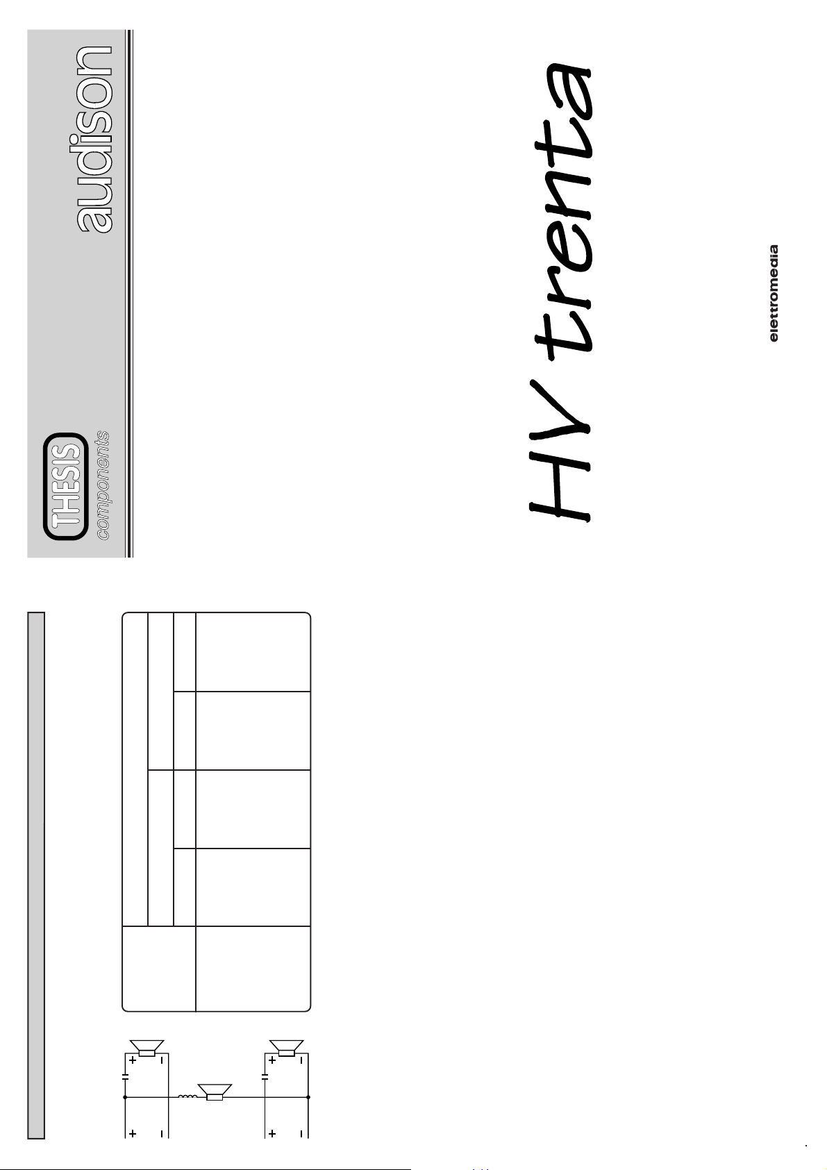
330
245
200
165
132
10.6
330
5.3
8.5
265
4.3
100
6.4
200
3.2
C µF
8 Ohms
21.0
15.9
660
10.6
495
7.9
12.7
400
6.4
L mH
C µF
4 Ohms
LOUDSPEAKERS IMPEDANCE
L mH
Strada Regina Km 3,5 • I 62018 Potenza Picena (MC) • Tel.0733/870.870 • Fax 0733/870.880 • http://www.audison.com
PRINTED IN ITALY - Code 10124700-A
8
60
80
100
120
150
HI
200
PASS
TRI-MODE CONNECTION (fig. 1)
Hertz
FREQUENCY
HI
PASS
SUBWOOFER
Page 2

REGULATIONS
All controls are located on top of the device.
- MONO ON-OFF: see MONO connection.
- BALANCED-UNBALANCED: see balanced-unbalanced connection.
- PREAMP ON-OFF: see connection to external preamplifier.
- L-R LEVELS: amplifier sensitivity adjustment , separated for the two channels.
PROCEED AS FOLLOWS
Adjust the device according to the head unit requirements, through the above
mentioned controls and regulations.
1) Set the two L-R LEVELS potentiometers towards minimum (counterclockwise).
2) Turn the head unit volume control to about 3/4 of its maximum volume.
3) Set the two L-R LEVELS towards maximum sensitivity until you get sporadic
lighting of PEAK R-PEAK L leds with high dynamic musical passages.
IMPORTANT: if you should hear distortion phenomena without the PEAK L-R leds
lighting up, it means that a distorted signal is coming from the head unit. In this case,
turn the head unit volume down until there’s no longer any distortion. Repeat
calibration operation omitting step 2.
PROTECTIONS
The device is provided with several electronic protections which protect the amplifier
from dangerous or wrong functioning conditions , avoiding to interfere with the music
signal in order to get the best performances in every condition.
- Outputs protection: any type of short circuit on the speaker wires , be it between
themselves or to ground , will cause no damages.
- Temperature protection: anomalous use conditions or high ambience temperature
(above 60°C), that doesn’t allow the amplifier to discharge the produced heating
(maximum working temperature of the device 80°C), causes the protection intervention.
- Protection against inverted polarity of the power supply: if the power supply cables
polarities should be mistakenly inverted, the electronic circuitry will be protected by
burning the external fuse, that will have to be replaced with an identical one.
- Protection against continuous current in the output.
- Protection against excessively low or dangerous loads.
A front red LED (SAFE) indicates intervention of protection circuits. Once the cause
of malfunctioning is eliminated, you need to turn head unit off and turn it back on in
order to have the device function again. The amplifier will function normally.
7
INTRODUCTION
The HV trenta amplifier begons on the new family of high performance car amplifiers
and other devices called THESIS.
It is endowed with highly innovative technologies and circuit solutions and its realization
required big efforts and investments for research and development.
The purpose was to realize an amplifier that had to be a "milestone" in the evolutive history
of AUDISON products.
Its structure in the circuit layout can be identified at two levels: the first one (power) is
entirely on the mother circuit board and it collects all components which handle high
currents and need warmth dissipation; the second one (signal and control) is located on
special surface mounting devices which perform all complex functions of the whole
device.
This peculiar design technique allowed the study and optimization of the signal paths and
the blocking of the interactions among the different stages.
The HV trenta amplifier is constituted by three main parts: preamplifier, final power
stage and power supply.
PREAMPLIFIER
HV trenta amplifier is supplied with an independent preamplifier unit, where the general
sensitivity can be adjusted in the 0.2÷1V range.
This unit can be disactivated, allowing the connection with an external preamplifier.
The input signal is applied to ABS (Audison Balanced System) connector in balanced or
2
unbalanced way, and to MA-1X module through two polypropylene capacitors.
MA - 1X circuit, which constitutes the input interface for audio signals, is characterized
by a FET- BJT hybrid circuitry in CASCODE configuration and it has been superintegrated
in a single chip whose features are: max power supply: ±50 VDC, S/N ratio: 125 dBA,
Slew Rate: 120 V/µS, Bandwidth: DC÷1MHz.
FINAL POWER STAGE
Balanced or unbalanced audio signal (it can be selected) applied to the input can directly
drive the final stage without the preamplifier interposition.
By disactivating, the preamplifier, the final stage sensitivity can be between 1.0 ÷5 V.
The signal coming from the MA-1X module arrives in balanced connection to the
V-AMP 12 LV module which makes the driving of the final stages in voltage and the
thermic stability control.
The internal circuit is characterized by a double complementary differential amplifier in
CASCODE connection with FET-BJT and current mirror combination. This circuit is
integrated in two custom chips (CDAP - CDAN) whose components undergo a laser trim
for the maximum tolerances reduction.
Page 3

POWER SUPPLY
The switching power supply is composed by a PWM controlled push-pull double power
Then there is a complementary voltage amplifier stage in CASCODE configuration and
realised with BJT transistors.
These circuits have been duly polarised and configured as transconduttance modulators
(HCP - HCN Hyperlinear correction) with filter functions for transient distortions.
Monotonic decreasing distortion spectrum with stop at the harmonic sixth.
The final stage driven by the above mentioned module is a complementary symmetric
inverted triplet configuration and it is supplied with a driver and predriver at low Cob and
The electrical features of the V-AMP 12LV section are: THD distortion at 100 Vpp:
0.04%; Sleaw Rate: 250/µS; Baudwidth: DC÷1.5 MHz; S/N: ratio 122 dBA.
five + five transistors amplifiers of 150 W, 15 A with Ft of 30 MHz.
min. 0.1 % at 300 W; Slew Rate: 90 V/µS.
The total reaction rate used in this amplifier is of 4 dB and the global performances
obtained by the whole amplifier stage are: bandwidth 1.5 Hz÷180 KHz; THD distortion:
supply. One of them generates and controls only positive voltages, the other one the
negative voltages. The power supply system functioning logic is directed by a single
circuit, called PWM CONTROLLER, which also attends to the PWM generation in the
positive power supply and operates in a synchronic way with a second circuit called PWM
SERVEUR, which has the task of making the PWM control of the negative power supply.
Synchronism between the two PWM generator clocks avoids the formation of residual
products at low frequency which could be converted into audio disturbance noises by the
amplifier.The particular dynamic control of the audio amplifier voltages allows the
voltage linear levelling and is able to supply energy instantaneously.
measurable result of such a complex controlling system is to have a "ripple" on the
transformer voltage equal to 300 mV when the HV trenta is loaded at the maximum
power on resistive load.
This control is active up to the frequency of about 800 Hz; the levelling at upper load
frequencies is given to the transformer capacities which are equal to 19500 µF. The
As it regards the sound, the fact that we have a perfectly stabilised power supply voltage
for the final stage allows the correct reproduction of high dynamic content transient
3
at ±60 V for the final stage driver circuit.
signals, it guarantees details, acoustic precision and very good reconstruction of sound
image.
The power supply delivers three secondary voltages: the first one is for the final power
The power supplies are provided with a primary protection which interdicts their
functioning in case of non operative overloading, avoiding circuit damages.
All interactions between power supply and amplifier (secondary voltages control, muting
stage at ±53 V, the second one for the internal preamplifier at ±25 V and the third one
circuits control and reception of information about the final stage protection) are effected
through optocoupler circuits.
This solution avoids the transfer of the noises coming from the car electric device to the
car radio section.
OUTPUTS CONNECTION
THREADED CONNECTORS (Speaker L-R). Connect the speakers or the speakers passive
crossover according to polarities.
IMPORTANT: Never connect -R and -L outputs to ground or to each other.
If a crossover filter is used, be sure the two channels don’t have a common ground. An allen key
is provided for the terminals screws.
MONO CONNECTION
Position MONO push-button to ON. Use IN R input. Take the power output from the +L (LEFT)
and -R (RIGHT) terminal.
It’s possible to obtain MONO use just for SUBWOOFER frequencies and to have a STEREO
system for high frequencies using the TRIMODE configuration (pict.1); in this case leave
MONO push-button to OFF position and apply the connection system according to the picture.
Refer to chart for inductance and capacity values relative to the desired crossover frequency.
terminal inserting a fuse (provided) next to the battery itself.
- POWER terminal must be connected to the battery negative (ground) through the car chassis,
POWER SUPPLY CONNECTION
THREADED CONNECTORS (Power) ± . The battery positive is connected to the + POWER
taking care to guarantee an excellent electrical contact on a metallic point not covered with paint
or insulating materials of any kind.
For the electrical connections described, use adequate cables, with a minimum diameter of 6 mm
(3 A.W.G.). An allen key is provided for the terminal screws.
TURN ON CONTROL CONNECTION
THREADED CONNECTORS (Remote in-out). Connect the amplifier REMOTE IN input to
the proper head unit output (REMOTE AUX), or to electric antenna control. REMOTE OUT
output is used to turn on another possible device. A green LED ON indicates when the amplifier
is turned on.
MUTING CONTROL CONNECTION
6
THREADED CONNECTORS (Mute in-out). MUTE IN input silences the amplifier.
The device goes into muting when it receives a positive voltage between 3 VDC and 15 VDC,
or when ground (GND) is applied.
MUTE IN can be connected to the proper head unit output (if provided) or to the MUTE output
of a cellular phone; in this case , when there is a phone call, the car system is silenced. When the
conversation is over, the amplifier will automatically play again.
The amplifier MUTE OUT contact must be connected to a second amplifier (if available)
provided with a special MUTE IN output. In this way, the second amplifier becomes dependent
on the first one as far as the car system MUTE functions are concerned.
Page 4

INSTALLATION
The HV trenta use 6 self-threading screws provided.
IMPORTANT: The wooden moulding which protects controls on top of the device must
be removed before installing. This is done by loosening the three screws through the 5mm
allen key provided. Once the installation and calibration have been made, mount the wooden
protective moulding. For excellent results it’s advised to use audison cable products to
complete your installation. They include: power cables, signal cables, speaker wires, signal
connectors and all accessories needed to complete the wiring.
INPUTS CONNECTIONS
Pin ABS CONNECTORS (Inputs). Observing polarity, connect L-R inputs to respective
preamplified outputs of radio-cassette player, preamplifier or electronic crossover. In order
to make UNBALANCED signal connections (traditional connection), it’s possible to use
pin RCA connectors used in almost all electronics on the market. In order to make
BALANCED signal connections ( taking the signal from a balancer-preamplifier outputs)
it’s necessary to use ABS signal connectors which you can find in audison cable catalogue.
In case of unbalanced connection and in case the radio-cassette player doesn't share the signal
GND (preamplified outputs) with the battery GND (chassis of the device itself), the shield
of the shielded cable must be connected to the radio-cassette player chassis.
BALANCED-UNBALANCED CONNECTION
Balanced: Position BALANCED-UNBALANCED push-button to BALANCED. For the
amplifier inputs use the ABS connectors in Audison cable catalogue taking the preamplified
signal from a device provided with balanced outputs.
Unbalanced: Position BALANCED-UNBALANCED push-button to UNBALANCED.
In the UNBALANCED position device can be used in the unbalanced way (traditional way)
and it’s therefore possible to employ common Pin RCA signal connectors. For sensitivity
values , refer to the technical features chart on the controls area of the device.
CONNECTION TO EXTERNAL PREAMPLIFIER
Position the PREAMP push-button to OFF position (internal preamplifier exclusion). In this
case the amplifier sensitivity decreases and it is necessary to connect the device inputs to an
external preamplifier.
The sensitivity can be adjusted from a maximum of 1.0 VRMS to a minimum of 5.0 VRMS
in unbalanced configuration (±0.5 VRMS to ±2.5 VRMS balanced).
With the PREAMP push-button to ON position (internal preamplifier on), the sensitivity
changes from a maximum of 0.2 VRMS to a minimum of 1.0 VRMS in unbalanced
configuration (±0.1 VRMS to ±0.5 VRMS balanced).
The chart on the controls area shows the different sensitivities according to the operative
modalities of the amplifier.
5
TECHNICAL FEATURES
POWER SUPPLY 11÷15 VDC
IDLING CURRENT 2.6 A
MAX CONSUMPTION (2 ch 4 Ohms) 60 A
CONT. NOMINAL POWER (Tol. + 10%; -5%)
2 ch x 4 Ohms; 0.3 % THD; 12 VDC 150 + 150 W (RMS)
CONTINUOUS OUT POWER (2 ch 4 Ohms; 13.8 VDC) 160 + 160 W (RMS)
CONTINUOUS OUT POWER (2 ch 2 Ohms; 13.8 VDC) 320 + 320 W (RMS)
CONTINUOUS OUT POWER (2 ch 1 Ohm; 13.8 VDC) 500 + 500 W (RMS)
CONT. OUT POWER (1 ch 4 Ohms; 13.8 VDC) Bridge 640 W (RMS)
CONT. OUT POWER (1 ch 2 Ohms; 13.8 VDC) Bridge 1000 W (RMS)
DISTORTION - THD 0.1 %
DISTORTION - IMD 0.08 %
BANDWIDTH 1.5 Hz - 180 KHz
DAMPING FACTOR (4 Ohms) 100
RISE TIME 2.2 µS
SLEW RATE 60 V/ µS
S/N RATIO 102 dBA
TOTAL NEGATIVE FEEDBACK 4 dB
REMOTE IN 3 ÷ 15 VDC
REMOTE OUT 12 VDC - 150 mA
MUTE IN GND / 3÷15 VDC
MUTE OUT 12 VDC
PRE INPUT SENSITIVITY (unbalanced) 0.2÷1.0 VRMS
PRE INPUT SENSITIVITY(balanced) (± 0.2 ÷ ± 0.5 VRMS)
AMP INPUT SENSITIVITY(unbalanced) 1.0÷5.0 VRMS
AMP INPUT SENSITIVITY(balanced) (± 0.5 ÷ ± 2.5 VRMS)
INPUT IMPEDANCE 10 KOhms
LOAD IMPEDANCE (stereo) 8 - 4 - 2 - 1 Ohms
LOAD IMPEDANCE (bridge) 8 - 4 - 2 Ohms
SIZE BxHxL mm 256 x 60 x 406
SIZE BxHxL inch 10.08 x 2.35 x 15.98
4
2) It must be installed in a dry and well ventilated spot.
PRECAUTIONS
1) In order for this device to function properly it’s important that it is installed in a spot
3) Power supply voltage is 12 VCC, negative to ground. Make sure that the characteristics
of the vehicle electrical system are suitable.
4) For safe driving, it’s advised to listen to music at a volume level that won’t drown out
where the temperature is beetween 0°C (32°F) and 55°C (131°F)
external traffic noise.
 Loading...