

Page 1
AM/FM/MPX RADIO WITH
STEREO CASSETTE PLAYER
RADIO AM/FM/MPX AVEC
LECTEUR DE CASSETTES STÉRÉO
RADIO AM/FM/MPX CON
TOCACINT AS ESTÉREO
OO
OO
O
WNER'S MAWNER'S MA
WNER'S MAWNER'S MA
WNER'S MA
NUALNUAL
NUALNUAL
NUAL
MAMA
MAMA
MA
NUEL DE L'UTNUEL DE L'UT
NUEL DE L'UTNUEL DE L'UT
NUEL DE L'UT
ILISAILISA
ILISAILISA
ILISA
TEURTEUR
TEURTEUR
TEUR
MAMA
MAMA
MA
NUAL DE OPERNUAL DE OPER
NUAL DE OPERNUAL DE OPER
NUAL DE OPER
ACIÓNACIÓN
ACIÓNACIÓN
ACIÓN
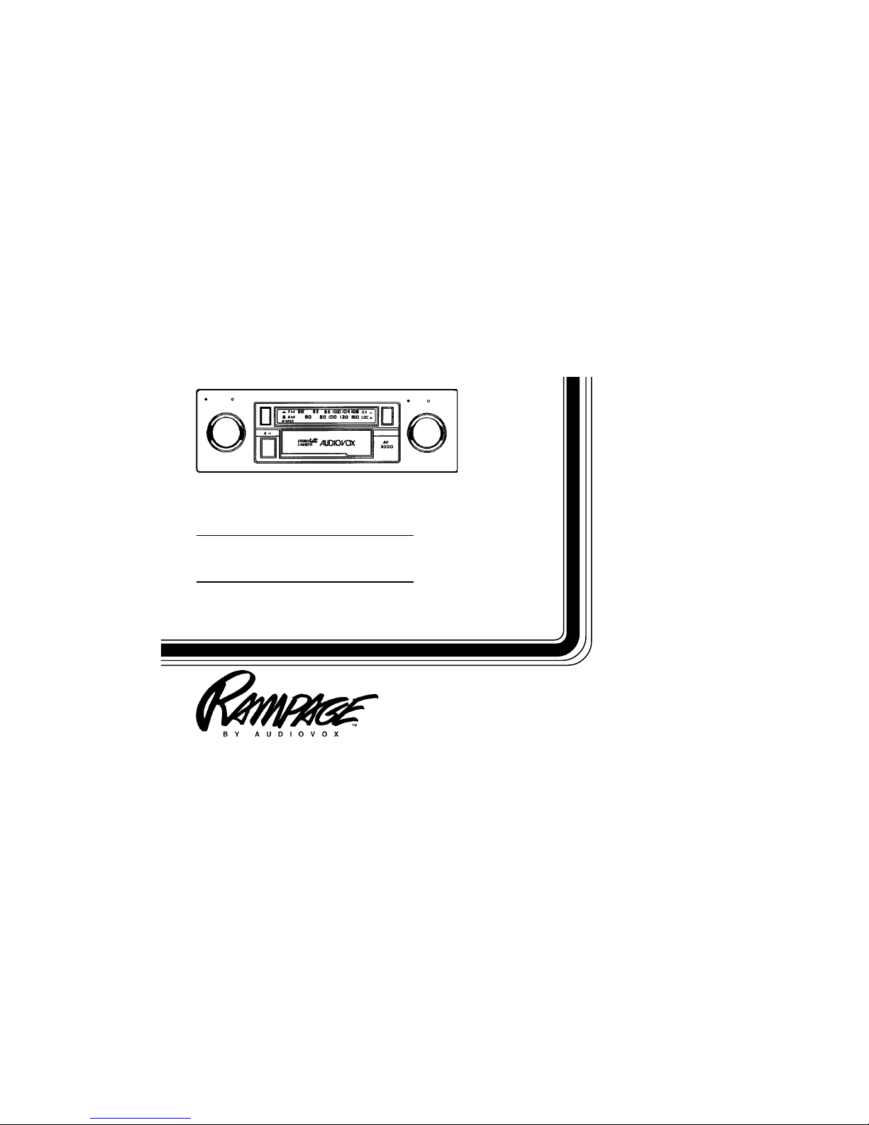
AV-3000
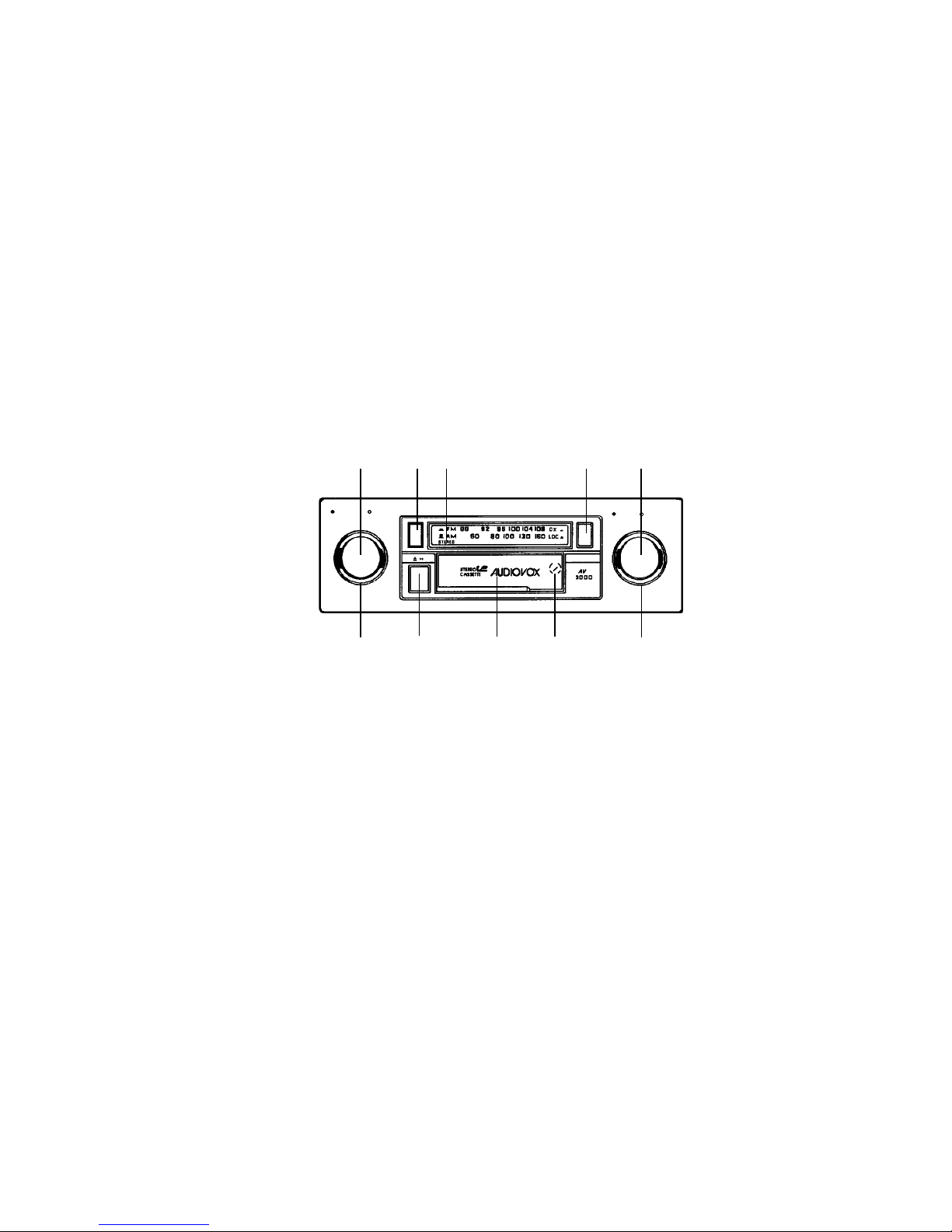
OFF VOL TONE
TUNE BALANCE
Page 2
-1-
8
bl 79
32
5641
OPERATING INSTRUCTIONS
4 AM/FM BAND SELECTOR
Press this button to change the radio band from AM to
FM. FM broadcasts will be received with the switch in the
“in” position, and AM broadcasts will be received with the
switch in the “out” position.
5 MANUAL TUNING CONTROL
Rotate this knob to the left or right to select the desired
radio station. When tuning in a station, always adjust
the control so that you are receiving the full signal and
are on the center of the broadcast frequency. If the radio
1 ON-OFF SWITCH/VOLUME CONTROL
Rotate this knob to the right to turn the unit on. Continue
rotation until desired volume level is obtained.
2 TONE CONTROL
Rotate this knob to the right or left to adjust the bass and
treble levels to suit your listening preference.
3 LEFT/RIGHT BALANCE CONTROL
Rotate this knob to the left or right to obtain the desired
balance between the left and right channel speakers.
OFF VOL
TONE
TUNE
BALANCE
Page 3

-2-
maximum signal to the receiver. When in an extremely
strong (local) signal area, set the switch to the Local
setting (“out” position). This will eliminate weak signals
and suppress overly strong signals so as to avoid
overloading the receiver input. When moving out of the
strong signal area, return the switch to the Distant (in)
setting.
NOTE: The Local/Distant Selector only affects FM sig-
nals, and will have no effect on AM reception.
9 CASSETTE DOOR
Hold the cassette with the exposed tape edge to the right
and insert it into the cassette door. Depress fully until the
cassette is engaged and begins playing.
NOTE: Observe the cassette operation cautions in the
Care and Maintenance section of this manual.
bl FAST-FORWARD/EJECT BUTTON
This button performs two functions. To eject a cassette,
simply depress the button fully then release. The
cassette will eject and radio operation will resume.
To fast-forward the tape, depress the button half-way in
to the locked position. To stop fast-forward and resume
normal tape playback, depress the button slightly and
release. Do not press fully in or the cassette will be
ejected.
NOTE: Never leave a cassette engaged in the player
when not in use. Doing so can cause damage to
the cassette and/or mechanism of the unit. Always press the eject button and remove the
cassette when leaving the vehicle.
is off frequency, you could experience noise and reception problems. The dial pointer will move along the dial
to indicate the frequency to which you are tuned.
6 FM STEREO INDICATOR
This indicator will illuminate during reception of FM
stereo broadcasts. If the indicator flickers or goes on
and off as you drive, it is an indication that the stereo
signal is too weak to reproduce clearly and you should
select another station.
7 AM ANTENNA TRIMMER
It is very important to adjust the Antenna Trimmer for
optimum AM reception. The antenna trimmer is located
at the back of the tape slot. Adjust it as follows:
1. Tune in a weak station around 1400 KHz on the AM
band.
2. Using a small screwdriver, slowly adjust the trimmer
for maximum output from the radio.
NOTE: The Antenna Trimmer only affects AM reception,
and will have no effect on FM reception. The
Trimmer only needs to be adjusted when the
radio is first installed and at any time a change
is made to the vehicle antenna (replacing the
mast, etc.).
8 FM LOCAL/DISTANT SELECTOR
This selector switch is incorporated to allow maximum
reception in both weak and strong FM signal areas. For
normal reception conditions and when receiving a wide
range of signals including weak or distant stations, the
switch should be set to the “in” position, which will allow
Page 4

CARE AND MAINTENANCE
The radio portion of your new sound system does not require any maintenance. We recommend you keep this
manual for general reference of the many features found in this unit.
As with any cassette player, the cassette section of this sound system does require a minimum of maintenance to
keep it in good working condition. The following simple care and maintenance suggestions should be followed to
prevent malfunctions of the cassette system.
-3-
Cassette Care:
1. Purchase a cassette cleaning kit from your local retail store. Use it! At least every 20 to 30 hours of operation
you must clean the cassette mechanism. A dirty cassette player will have a poor sound.
2. Do not use cassettes that exceed 45 minutes of play on each side.
3. Do not insert a cassette that appears to be broken, twisted or dirty or with loose or torn labels on it.
4.
Always keep your cassettes away from direct sunlight or exposure to sub-freezing conditions. If a cassette
is cold, allow it to warm up before use.
5. Do not keep a cassette in the player when not in use.
6. Before inserting a cassette in the player, check that the tape is tightly wound on the reels.
Take up any excess slack using a pencil to turn the drive hub in the cassette (see diagram).
7" W x 2" H x 4-1/2" D (178mm x 50mm x 115mm)
12 volts DC, negative ground
14 watts maximum ( 7 watts x 2 channels)
Common-ground type designed for 2 speaker use.
May also be used with 4 speakers.
Compatible with 4-8 ohm speakers
AM: 540 - 1,710 KHz., FM: 88 - 108 MHz.
AM: 15 uv., FM: 2.5 uv.
30 dB
50-10,000 Hz.
50 dB
0.25% WRMS
Size:
Operating Voltage:
Output Power:
Output Wiring:
Output Impedance:
Tuning Range:
Sensitivity:
FM Stereo Separation:
Tape Frequency Response:
Tape S/N Ratio:
Wow & Flutter:
SPECIFICATIONS
* Specifications are subject to change without notice.
Page 5

12 MONTH LIMITED WARRANTY
AUDIOVOX CORPORATION (the Company) warrants to the original retail purchaser of this product that should this product
or any part thereof, under normal use and conditions, be proven defective in material or workmanship within 12 months from
the date of original purchase, such defect(s) will be repaired or replaced with new or reconditioned product (at the Company's
option) without charge for parts and repair labor.
To obtain repair or replacement within the terms of this Warranty, the product is to be delivered with proof of warranty coverage
(e.g. dated bill of sale), specification of defect(s), transportation prepaid, to the warranty center at the address shown below.
This Warranty does not extend to the elimination of car static or motor noise, to correction of antenna problems, to costs
incurred for installation, removal, or reinstallation of the product, or damage to tapes, compact discs, speakers, accessories,
or vehicle electrical systems.
This Warranty does not apply to any product or part thereof which, in the opinion of the Company, has suffered or been
damaged through alteration, improper installation, mishandling, misuse, neglect, accident, or by removal or defacement of
the factory serial number/bar code label(s). THE EXTENT OF THE COMPANY'S LIABILITY UNDER THIS WARRANTY IS
LIMITED TO THE REPAIR OR REPLACEMENT PROVIDED ABOVE AND, IN NO EVENT, SHALL THE COMPANY'S
LIABILITY EXCEED THE PURCHASE PRICE PAID BY PURCHASER FOR THE PRODUCT.
This Warranty is in lieu of all other express warranties or liabilities. ANY IMPLIED WARRANTIES, INCLUDING ANY IMPLIED
WARRANTY OF MERCHANTABILITY, SHALL BE LIMITED TO THE DURATION OF THIS WRITTEN WARRANTY. ANY
ACTION FOR BREACH OF ANY WARRANTY HEREUNDER INCLUDING ANY IMPLIED WARRANTY OF MERCHANTABILITY MUST BE BROUGHT WITHIN A PERIOD OF 30 MONTHS FROM DATE OF ORIGINAL PURCHASE. IN NO CASE
SHALL THE COMPANY BE LIABLE FOR ANY CONSEQUENTIAL OR INCIDENTAL DAMAGES FOR BREACH OF THIS
OR ANY OTHER WARRANTY, EXPRESS OR IMPLIED, WHATSOEVER. No person or representative is authorized to
assume for the Company any liability other than expressed herein in connection with the sale of this product.
Some states do not allow limitations on how long an implied warranty lasts or the exclusion or limitation of incidental or
consequential damage so the above limitations or exclusions may not apply to you. This Warranty gives you specific legal
rights and you may also have other rights which vary from state to state.
U.S.A. : AUDIOVOX CORPORATION, 150 MARCUS BLVD., HAUPPAUGE, NEW YORK 11788 " (800) 225-6074
CANADA: CALL 1-800-645-4994 FOR LOCATION OF WARRANTY STATION SERVING YOUR AREA
AUSTRALIA: AUDIOVOX PACIFIC PTY LTD., DOYLE AVENUE, UNANDERRA, NSW 2526 " (042) 718-555
NEW ZEALAND: AUDIOVOX PACIFIC PTY LTD., UNIT B, 6 HENDERSON PLACE, PENROSE, AUCKLAND " (09) 645-720
-4-
Form No. 128-4270C1
Page 6

INSTALLATION INSTRUCTIONS
This unit is designed for installation in cars, trucks, and vans with an existing radio opening. In many cases, a special installation
kit will be required to mount the radio to the dashboard. These kits are available at electronics supply stores and car stereo
specialist shops. Always check the kit application before purchasing to make sure the kit works with your vehicle. If you need a
kit but cannot find it available, call our toll-free “HELP” line.
UNIVERSAL INSTALLATION
1. Inspect the Existing Radio Opening
A. Use the trimplate supplied with the radio to cover the existing dashboard opening. If it completely covers the opening, you can
install the radio without an installation kit. If it does not cover the opening, you will need an installation kit.
B. Check that there will be sufficient space behind the dashboard for the radio chassis.
2. Wire the Radio to the Vehicle’s Wiring
A. In most cases, it is easier to wire the radio before mounting it. Place the radio near the dashboard so the wires can be led through
the opening.
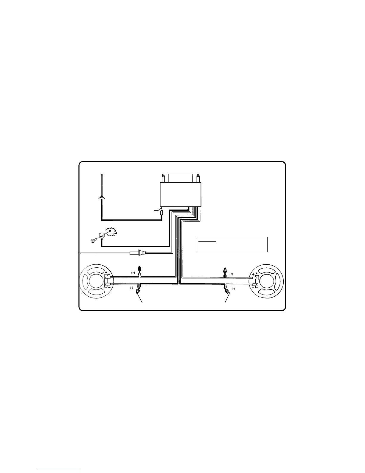
B. Carefully follow the wiring diagram in this manual and make certain all connections are secure and insulated with wire nuts or
electrical tape to insure proper operation of the unit.
C. After completing the wiring, turn the unit on to confirm operation (ignition switch must be “on”). If unit does not operate, re-check
all wiring until the problem is corrected. Once proper operation is achieved, turn off unit and ignition switch, and proceed with
final mounting of the radio.
3. Mounting the Radio
A. Thread a shaft nut half-way down each radio shaft.
B. Place a metal back-up plate on each radio shaft against the shaft nut.
C. Position the radio behind the dashboard opening so that the back-up plates are snug against the back of the opening. Adjust the
shaft nuts behind the back-up plates so that the desired amount of radio nosepiece extends through the opening. The best
appearance is usually achieved when there is just enough of the radio extending to be flush with the front of the trimplate.
D. Place the trimplate over the front of the radio and secure it with a shaft nut on each radio shaft.
E. Attach one end of the perforated support strap (supplied) to the screw stud on the radio using the hex nut provided. Bend the
strap to position it as necessary.
CAUTION: The rear of the radio must be supported with the strap to prevent damage to the dashboard from the weight of the radio
or improper operation due to vibration.
F. Install knobs on the radio.
INSTALLATION USING KITS
1. If your vehicle requires the use of an installation kit to mount this radio, follow the instructions included with the installation kit to attach
the radio to the mounting plate supplied with the kit.
2. Wire and test the radio as described in section 2 above.
3. Install the radio/mounting plate assembly to the sub-dashboard according to the instructions of the installation kit.
4. Attach the support strap to the radio and dashboard as described in section 3-E above.
5. Replace the dashboard trimpanel and install knobs on the radio shafts.
-5-
Page 7
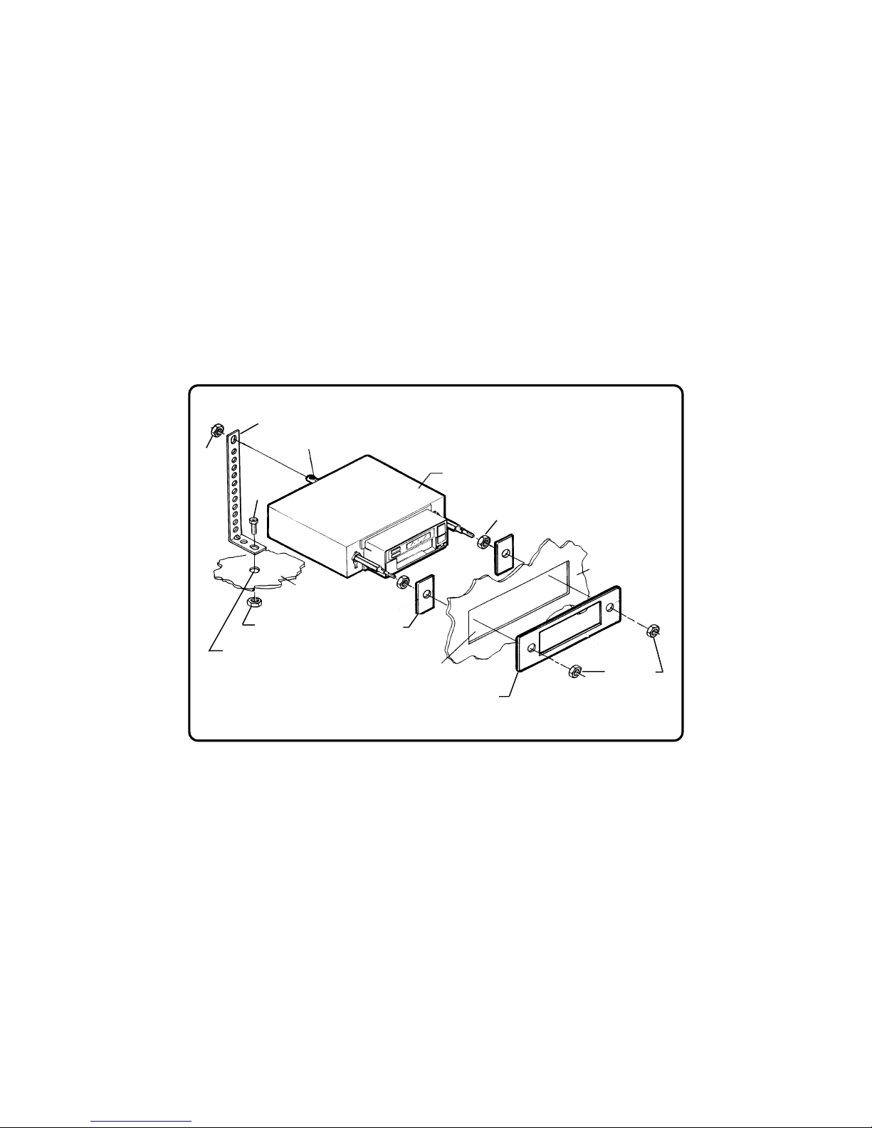
PERFORATED STRAP
SCREW STUD
TRIMPLATE
EXISTING OPENING
METAL PART OF
DASHBOARD
HEX NUT
SCREW
SHAFT NUT
DASHBOARD
RADIO
SHAFT NUTS
BACK-UP PLATE
HEX
NUT
DRILL HOLE IF NECESSARY
UNIVERSAL INST ALLATION
-6-
Page 8
-7-
ANTENNA SOCKET
ON REAR OF RADIO
WIRING DIWIRING DI
WIRING DIWIRING DI
WIRING DI
AA
AA
A
GRGR
GRGR
GR
AA
AA
A
MM
MM
M
VIOLET
WHITE
LIGHT GREEN
YELLOW
USE WIRE NUTS OR SOLDER AND TAPE ALL SPLICES
LEFT SPEAKER
RADIO
BLACK w/WHITE STRIPE
ORANGE w/WHITE STRIPE
GROUNDED METAL PART
OF CAR BODY
(REMOVE ANY PAINT)
EXISTING ANTENNA CABLE
ANTENNA
4 - 8 OHMS
IMPORTANT
CONNECT THE ORANGE w/WHITE STRIPE WIRE
TO A SWITCHED +12 VOLT SOURCE.
RIGHT SPEAKER
4 - 8 OHMS
Page 9
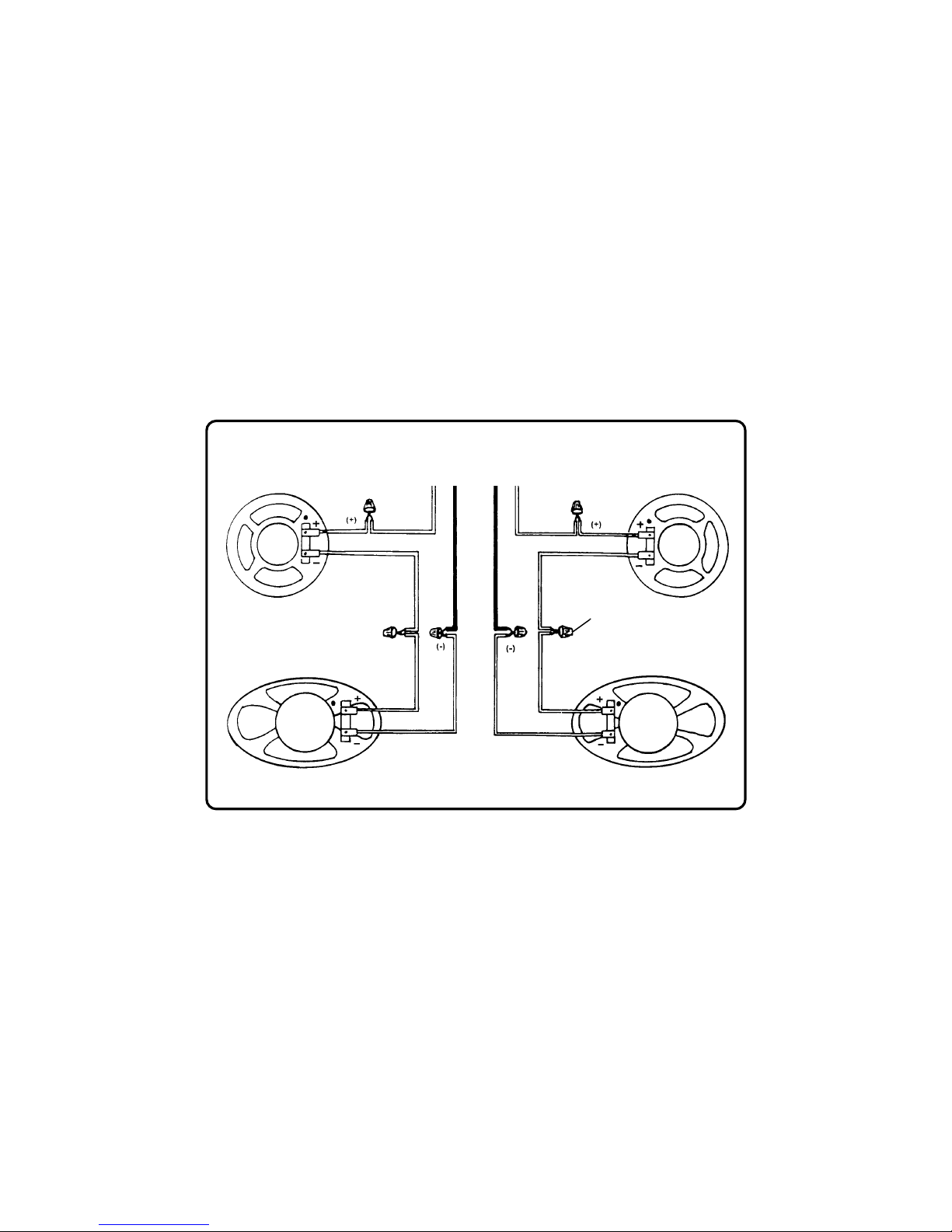
-8-
LEFT FRONT SPEAKER
RIGHT FRONT SPEAKER
WHITE
TO RADIO
YELLOW
LEFT REAR SPEAKER
RIGHT REAR SPEAKER
4 SPE4 SPE
4 SPE4 SPE
4 SPE
AA
AA
A
KK
KK
K
ER SYER SY
ER SYER SY
ER SY
STEM WIRINGSTEM WIRING
STEM WIRINGSTEM WIRING
STEM WIRING
NOTE: CONNECT ALL OTHER WIRES AS SHOWN ON PAGE 7.
USE WIRE NUTS OR SOLDER
AND TAPE ALL SPLICES
VIOLET
LIGHT GREEN
Page 10

41
3
9
bl
2
7
58
6
MODE D'EMPLOI
1 COMMUTATEUR MARCHE-ARRET
COMMANDE DE VOLUME
Faites tourner ce bouton vers la droite pour mettre la
radio en marche. Continuez de le faire tourner jusqu’à
obtenir le volume sonore désiré.
2 REGLAGE DE TONALITE
Permet à l’utilisateur d’accentuer les aigus ou les graves
selon ses préférences d’écoute. Tourner en sens horaire
pour accentuer les aigus, en sens anti-horaire pour
accentuer les graves.
3 REGLAGE D’EQUILIBRE GAUCHE-DROITE
Permet à l’utilisateur d’ajuster l’équilibre stéréophonique
entre les haut-parleurs gauche et droit. Tourner en sens
horaire pour accentuer le haut-parleur droit, en sens
anti-horaire pour accentuer le haut-parleur guache.
4 SÉLECTEUR AM/FM
Appuyer sur ce bouton pour passer de la bande AM à la
bande FM. La programmation FM et FM stéréophonique
sera reçue lorsque le bouton est enfoncé. La
programmation AM sera reçue lorsque le bouton est
sorti (appuyer et relâcher).
-9-
OFF VOL
TONE
TUNE
BALANCE
Page 11

5 SYNTONISATION MANUELLE
La station peut être changée manuellement en tournant
le bouton. Lorsque cette commande est utilisée pour
sélectionner une station, toujours la régler afin de recevoir
le plein signal (exactement au centre de la fréquence de
difusion). Du bruit et des problèmes de réception
pourraient survenir si la station est mal syntonisée.
L’aiguille de cadran se déplacera le long du cadran pour
indiquer la fréquence syntonisée.
6 VOYANT STÉRÉO (ROUGE)
S’allumera lorsque’une station stéréo est sélectionnée.
Si le voyant clignote ou s’allume et s’éteint en conduisant,
ceci signifie que le signal stéréo est trop faible pour être
reproduit et qu’une autre station devrait être sélectionnée.
7 TRIMMER D’ANTENNE
Pour un réception optimale en AM, il importe au plus
haut point de réglar le COMPENSATEUR D’ANTENNE.
Le compensateur d’antenne est situé à l’arrière de
l’appareil, dans la cavité destinée à la cassette. Régler
le poste sur une station à signal faible, 1400KHz environ,
et régler le compensateur au moyen d’un petit tournevis
jusqu’à obtenir la réception maximale.
8 COMMUTATEUR LOCAL-DISTANT
Ce commutateur à deux positions incorporé permet une
réception maximale dans les zones de signal FM fort et
faible. Appuyer sur le commutateur lorsqu’une station
faible (distante) est syntonisée. Le signal sera ainsi
mazimalisé au récepteur. Relâcher le commutateur
dans une zone de signal extrêmement fort (local). Ceci
éliminera tous les signaux faibles et supprimera les
signaux trop forts afin d’éviter de surcharger l’entrée du
récepteur. Remettre le commutateur à la positiion
“distante” en sortant d’une zone de signal fort.
Remarque: Le commutateur local-distant ne modifie
que les signaux FM.
9 FENTE D’INSERTION DE CASSETTE
Tenir la cassette avec le bord exposé de la bande vers
la droite et insérer dans la fente de cassette. Appuyer à
fond jusqu’à ce que la cassette soit engagée. La lecture
commencera immédiatement.
Remarque: Vérifier que la bande est entroulée
fermement sur les bobines avant d’insérer.
Les cassettes C-120 (120 minutes) ne
doivent pas être utilisées car la bande
s’emmêle facilement.
bl BOUTON AVANCE RAPIDE/EJECTION
Ce bouton remplit deux fonctions. Pour éjecter une
cassette, appuyer simplement à fond sur ce bouton puis
relâcher, ce qui permettra de retirer facilement a cassette une fous éjectée. Ce bouton permettra aussi de
faire avancer rapidement la bande afin de suter tout
programme que l’on desire éliminer. Pour avancer
rapidement, appuyer sur ce bouton jusqu’à mi-course et
verrouillage. Pour arrêter l’avance rapide, appuyer
délicatement sur le bouton (ne pas appuyer à fond, ce
qui éjecterait la cassette) et relâcher. La bande
recommencera à avancer à vitesse normale.
-10-
Page 12

SOINS ET ENTRETEIN
LECTEUR DE CASSETTES
1. Ne pas employer de cassettes de 120 minutes (C-120).
2. Nettoyer le mécanisme de déroulement de la cassette et la tête de lecture au bout de 30 heures de fonctionnement
et, en tout état de cause, au moins une fois tous les deux mois, au moyen d'une cartouche de nettoyage disponible
dans le commerce.
3. Ne jamais introduire une cassette dans le lecteur si la température de ce dernier ou de la cassette est inférieur
du véhicule.
4. Toujours vérifier la cassette avante de l'introduire dans le lecteur. Si la bande est déroulée, la resserrer comme
indiqué dans le graphie.
5.
Prière de lire le manuel avante de mettre l'appareil en route. Ce lecteur comporte en effet nombre de
caractéristiques et d'améliorations techniques qui ne vous sont peut-être pas familières.
Dimension:
Voltage:
Puissance:
Connexion sortie:
Impédance de sortie:
Bande passante:
Sensibilité:
Séparation stéréo en FM:
Réponse-fréquence:
Rapport signal/bruit:
Papillottement et pleurage:
SPÉCIFICATIONS
178mm (L) x 50mm (H) x 115mm (P)
12 volts, tension continue négative
14 watts de puissance maximum (7 watts x 2 canals)
Type terre conçu pour deux haut-parlers. Peut être
utilisé avec quatre haut-parleurs.
Compatible avec les haut-parleurs de 4 à 8 ohms.
AM: 540-1,710 KHz, FM: 88-108 MHz
AM: 15 uv., FM: 2.5uv.
30 dB
50-10000 Hz.
50 dB
0,25%
-11-
Page 13

AUDIOVOX CORPORATION (la Société) garantit à l’acheteur initial du produit que si tout ou partie de ce produit, en cours d’utilisation
et sous des conditions normales, venait à présenter des vices de matière primitive ou des défauts de fabrication, dans les 12 mois
suivant la date d’achat initial, ce(s) défaut(s) sera(seront) réparé(s) ou remplacé(s) par un produit neuf ou reconditionné (au choix de
la Société), sans frais de pièces ni de main-d’oeuvre.
Pour obtenir réparation ou remplacement selon les termes de cette Garantie, le produit doit être renvoyé, accompagné d’une attestation
de garantie (par ex., ticket de caisse daté), d’une description du(des) défaut(s), transport prépayé à un centre de garantie à
l'adresse indiquée ci-dessous.
Cette Garantie ne couvre pas la suppression de l’électricité statique ou des bruits du moteur, la correction des problèmes
d'antenne, les coûts engendrés par l'installation, l'enlèvement ou la réinstallation du produit, ou les dégats subis par les
cassettes, les disques compacts, les haut-parleurs, les accessoires ou les circuits électriques du véhicle.
Cette Garantie ne s’applique pas à tout ou partie de produit qui, de l’avis de la Société, a été endommagé en raison ou au cours de
modification, installation incorrecte, défaut de manipulation, emploi abusif, négligence, accident, ou lors du retrait ou de la dissimulation
de l’(des) étiquette(s) portant le numéro de série de l’usine ou le code barres. SELON LES TERMES DE CETTE GARANTIE, LA
RESPONSABILITE DE LA SOCIETE EST LIMITEE A LA REPARATION OU AU REMPLACEMENT, TEL(LE) QU’IL(ELLE) EST
STIPULE(E) CI-DESSUS ET, EN AUCUN CAS, LA RESPONSABILITE DE LA SOCIETE NE POURRA EXCEDER LE PRIX
D’ACHAT PAYE PAR L’ACHETEUR DU PRODUIT.
Cette Garantie remplace toute autre garantie expresse ou responsabilité. TOUTE GARANTIE TACITE, COMPRENANT TOUTE
GARANTIE DE QUALITE LOYALE ET MARCHANDE, EST LIMITEE A LA DUREE DE CETTE GARANTIE ECRITE. TOUTE
ACTION POUR RUPTURE DE TOUTE GARANTIE, SELON LES TERMES DE LA PRESENTE, COMPRENANT TOUTE
GARANTIE IMPLICITE DE QUALITE LOYALE ET MARCHANDE, DOIT ETRE INTENTEE DANS LES 30 MOIS A COMPTER
DE LA DATE D’ACHAT INITIAL. EN AUCUN CAS LA SOCIETE NE SERA RESPONSABLE DE TOUT DOMMAGE INDIRECT
OU FORTUIT POUR RUPTURE DE CETTE GARANTIE OU DE TOUTE AUTRE GARANTIE, EXPRESSE OU IMPLICITE, DE
QUELLE QUE NATURE QUE CE SOIT. Aucune personne ni aucun représentant n’est autorisé(e) à assumer, au nom de la Société,
d’autre responsabilité que celle exprimée dans la présente, et se rapportant à la vente de ce produit.
Certains Etats n’autorise pas les restrictions relatives à la durée d’application des garanties implicites ni l’exclusion ou la limitation des
dommages indirects ou fortuits. Dans ces Etats, de telles limitations ou exclusions ne s’appliquent donc pas. Cette Garantie vous
donne des droits juridiques spécifiques et vous pouvez également jouir d’autres droits, suivant l’Etat dans lequel vous vivez.
ETATS-UNIS : AUDIOVOX CORPORATION, 150 MARCUS BLVD., HAUPPAUGE, NEW YORK 11788 " 800-225-6074
CANADA : COMPOSEZ LE 1-800-645-4994 CONNAÎTRE L'ADRESSE DU POSTE DE GARANTIE DE VOTRE RÉGION
AUSTRALIE : AUDIOVOX PACIFIC PTY LTD., DOYLE AVENUE, UNANDERRA, NSW 2526 " (042) 718-555
NOUVELLE-ZELANDE : AUDIOVOX PACIFIC PTY LTD., UNIT B, 6 HENDERSON PLACE, PENROSE, AUCKLAND " (09) 645-720
Formulaire n°128-4270C1
-12-
GARANTIE LIMITÉE DE 12 MOIS
Page 14

-13-
DIRECTIVES D’INSTALLATION
Cet appareil est conçu pour être installé dans une voiture, un camion ou une fourgonnette étant déjà doté d’une ouverture pour la radio. Dans bien des
cas, il faudra un nécessaire spécial d’installation pour monter la radio au tableau de bord. Ces nécessaires sont vendus dans les magasins de matériel
électronique et les ateliers spécialisés dans l’installation des chaînes stéréo d’auto. Vérifiez toujours l’utilisation indiquée du nécessaire avant de
l’acheter pour vous assurer qu’il convient à votre véhicule. S’il vous faut un nécessaire mais que vous ne parvenez pas à vous en procurez un,
composez le numéro de notre ligne d’assistance sans frais.
INSTALLA TION UNIVERSELLE
1. Inspectez l’ouverture pour radio existante
A. Utilisez la plaque de garnissage fournie avec la radio pour couvrir l’ouverture existante dans le tableau de bord. Si elle couvre complètement
l’ouverture, vous pouvez installer la radio sans nécessaire d’installation. Si elle ne couvre pas l’ouverture, vous devez vous procurer un nécessaire
d’installation.
B. Vérifiez qu’il y aura suffisamment d’espace derrière le tableau de bord pour y loger le châssis de la radio.
2. Câblez la radio au câblage du véhicule
A. Dans la plupart des cas, il est plus facile de câbler la radio avant de l’installer. Placez la radio près du tableau de bord afin de pouvoir passer les
fils par l’ouverture.
B. Suivez attentivement le diagramme de câblage de ce manuel et assurez-vous que tous les raccordements sont solides et isolés à l’aide de
capuchons de connexion ou de ruban isolant pour que l’appareil fonctionne correctement.
C. Après avoir terminé le câblage, allumez l’appareil pour vérifier qu’il fonctionne (la clé de contact doit être à la position de marche "on"). Si
l’appareil ne fonctionne pas, vérifiez à nouveau tout le câblage jusqu’à ce que le problème soit corrigé. Lorsque l’appareil fonctionne correctement,
fermez l’appareil, coupez le contact et procédez au montage final de la radio.
3. Montage de la radio
A. Vissez un écrou jusqu’au milieu de chaque tige de radio.
B. Placez une plaque d’appui métallique sur chaque tige de radio en l’appuyant sur l’écrou.
C. Insérez la radio dans l’ouverture du tableau de bord et positionnez-la de façon à ce que les plaques d’appui soient ajustées serrées à l’arrière de
l’ouverture. Ajustez les écrous derrière les plaques d’appui pour que la portion désirée du devant de la radio sorte par l’ouverture. Pour que le
tableau de bord ait belle apparence, le devant de la radio doit sortir suffisamment de l’ouverture pour être à même égalité que le devant de la
plaque de garnissage.
D. Mettez la plaque de garnissage sur le devant de la radio et fixez-la à chaque tige de la radio à l’aide d’un écrou.
E. Fixez une extrémité de la bande de soutien perforée (fournie) au goujon fileté de la radio à l’aide de l’écrou à six pans fournie. Pliez la bande pour
pouvoir la placer comme il faut.
ATTENTION: L ’arrière de la radio doit être soutenu par la bande pour éviter que le poids de la radio n’endommage le t ableau de bord ou que les
vibrations ne nuisent au bon fonctionnement de celle-ci.
F. Inst allez les boutons sur la radio.
INSTALLA TION À L’AIDE D’UN NÉCESSAIRE
1. Si vous devez utiliser un nécessaire d’installation pour monter la radio à votre véhicule, suivez les directives fournies avec le nécessaire d’installation
pour fixer la radio à la plaque de fixation fournie avec ce nécessaire.
2. Câblez la radio et vérifiez qu’elle fonctionne en suivant les directives de la section 2 ci-dessus.
3. Installez l’assemblage radio/plaque de fixation sur la partie située sous le tableau de bord selon les directives du nécessaire d’installation.
4. Fixez la bande de soutien à la radio et au tableau de bord comme l’indique la section 3-E ci-dessus.
5. Replacez le panneau de garnissage du tableau de bord et installez les boutons sur les tiges de la radio.
Page 15

BANDE PERFORÉE
CRAMPON A VIS
PLAQUE DE GARNISSAGE
L'EMPLACEMENT PRÉVU
ATTACHE EXISTANTE
DANS LE TABLEAU DE BORD
ECROU
VIS
ECROUS
TABLEAU DE BORD
RADIO
ECROUS
PLAQUE PERFORÉE
ECROU
PERCER SI NÉCESSAIRE
-14-
INSTALLATION UNIVERSELLE
Page 16

-15-
PRISE D'ANTENNE AU
DOS DE LA RADIO
SCHEMA DE CABLSCHEMA DE CABL
SCHEMA DE CABLSCHEMA DE CABL
SCHEMA DE CABL
AA
AA
A
GEGE
GEGE
GE
VIOLET
BLANC
VERT CLAIR
JAUNE
UTILISER DES ECROUS A FIL DU SOUDER ET APPLIQUER
DU RUBAN ISOLANT A TOUTES LES EPISSURES
HAUT-PARLEUR GAUCHE
POSTE DE RADIO
NOIR RAYE BLANC
ORANGE RAYE BLANC
VERS LA PIECE METALLIQUE
DE LA VOITURE (RETIRER
TOUTE PEINTURE)
LE FIL D'ANTENNE
ANTENNE
4 - 8 OHMS
IMPORTANT
BRANCHER LE FIL ORANGE RAYE BLANC
VERS LA SOURCE +12 VOLTS COMMUTEE.
HAUTE-PARLEUR DROIT
4 - 8 OHMS
Page 17

-16-
HAUT-PARLEUR AVANT GAUCHE HAUTE-PARLEUR AVANT DROIT
BLANC
Á LA RADIO
JAUNE
HAUT-PARLEUR ARRIERE GAUCHE
HAUT-PARLEUR ARRIERE DROIT
SYSY
SYSY
SY
STEME DES 4 HSTEME DES 4 H
STEME DES 4 HSTEME DES 4 H
STEME DES 4 H
AUTE-PAUTE-P
AUTE-PAUTE-P
AUTE-P
AA
AA
A
RLEURSRLEURS
RLEURSRLEURS
RLEURS
REMARQUE: RACCORDER TOUS LES AUTRES FILS COMME IL EST MONTRÉ A LA PAGE 15.
UTILISER DES ECROUS A FIL OU
SOUDER ET APPLIQUER DU RUBAN
ISOLANT A TOUTES LES EPISSURES
VIOLET
VERT CLAIR
Page 18

INSTRUCCIONES DE OPERACIÓN
-17-
1 INTERRUPTOR ON-OFF/CONTROL DE VOLÚMEN
Gire esta perilla hacia la derecha para encender la radio. Continúe girando hasta obtener el volúmen
deseado. Gire la perilla completamente hacia la
izquierda para apagar la radio.
2 CONTROL DE TONOS
Le permite acentuar los tonos bajos y agudos de acuerdo
con su preferencia de sonoridad. Gírelo hacia para
aumentar los agudos y hacia la izquierda para aumentar
los bajos.
3 CONTROL DE EQUILBIRIO ACÚSTICO IQUIERDO/
DERECHO
Le permite ajustar el balance estereofónico entre el
altavoz izquierdo y el derecho. Girelo hacia la derecha
para acentuar el altavoz derecho y hacia la izquierda
para acentuar el altavoz izquierdo.
4 SELECTOR DE BANDAS FM/AM
Oprima este botón para cambiar de banda AM a FM.
En la posición hacia adentro recibirá las transmisiones
FM y FM Estéreo. En la posición hacia afuera (oprima y
suelte el botón), recibirá las transmisiones AM.
5 CONTROL DE SINTONIZACIÓN MANUAL
Usted puede cambiar de estación girando manualmente
el botón. Cuando use este control para seleccional una
estación, siempre debe ajustarlo de manera que reciba
la señal completa (exactamente en el centro de la
41
3
9
bl
2
7
586
OFF VOL
TONE
TUNE
BALANCE
Page 19

frecuencia de transmisión). Si está fuera de la estsación
pdoria tener problemas de ruido y de recepción. La aguja
se moverá por el cuadrante indicando la frecuencia que
sintoniza.
6 INDICADOR DE ESTEREO
Esta indicador se encenderá cuando haya seleccionado
una estación estereofónica. Si la luz parpadea o se
apaga y enciende intermitentemente cuando maneja,
esto indica que la señal estereofónica es muy debil y
deberá seleccionar otra estación.
7 COMPENSADOR DE ANTENA
Es importante ajustar el compensador de antena para
óptima recepción AM. El compensador de antena está
situado detrás de la ranura de la cinta. Sintonize una
estación débil cerca de los 1400 KHz y ajuste el
compensador con un destornillador pequeño para lograr
una señal óptima de recepción.
NOTA: El ajuste del compensador de antena es
únicamente para la banda AM y no tiene ningún
efecto en la banda FM. Una vez ajustado, ningún
otro cambio más al compensador de antena será
requerido a menos que la antena, cable de la
antena, o longitud del mástil de la antena se
cambie, en cuyo caso, el compensador deberá
ser reajustado como se describe arriba.
8 COMMUT ADOR DE RECEPCION LOCAL-DIST ANT
Este conmutador de dos posiciones, permite una
recepción óptima de señales de FM, tanto débiles como
fuertes. Cuando la emisora sintonizada es débil
(distante) se aprieta el botón hacia adentro lo que
proporciona la señal máxima al receptor. Cuando se
está en una zona de señales extremadamente fuertes
(local), se debe sacar hacia afuera el botón, lo que
elimina todas las señales débiles y atenúa las señales
demasiado fuertes para evitar la sobrecarga de la
entrada del receptor. Cuando se sale de una zona de
señales fuertes, conmute nuevamente a la posición
distante marcada “DX”.
9 RANURA PARA CASSETTES
Sostenga el cassette con el borde de la cinta expuesta
hacia la derecha e introdúzcalo en la ranura del cassette. Empújelo totalmente hasta que el cassette
enganche. Comenzará a tocar inmediatamente.
NOTA: Compruebe que la cinta esté firmemente
enrollada antes de introduciria. No debe usar
cassettes C-120 (120 minutos) ya que la cinta
puede enredarse fácilmente.
bl BOTÓN PARA AVANCE RÁPIDO/EYECCION
Este botón realiza dos funciones. Para expulsar un cassette, sólo tiene que oprimir totalmente este botón y
luego soltarlo. El cassette se expulsará para poder
retirarlo fácilmente. Este botón también le permite
avanzar rápidamente la cinta para saltar cualquier
grabación que no desee. Para usar el avance rápido,
oprima el botón hasta la mitad en la posición de cierra.
Para detener el avance rápido, oprima ligeramente el
botón (no totalmente, ya que el cassette se expulsará)
y luego suéltelo. La cinta regresará a su velocidad normal.
-18-
Page 20

CUIDADO Y MANTENIMIENTO
La parte correspondiente a la radio de su nuevo sistema de audio no requiere ningún mantenimiento. Le
recomendamos guardar este manual para consultarlo más adelante para usarlo como referencia general en
relación con las muchas funciones que tiene esta unidad.
Al igual que cualquier otro reproductor de cassettes, la parte correspondiente al reproductor de cassettes de este
sistema de audio requiere un mínimo de mantenimiento para que continúe estando en buenas condiciones de
funcionamiento. Se deberán seguir las siguientes sugerencias para el cuidado y mantenimiento a fin de evitar
desperfectos del sistema de cassettes.
CUIDADO DE LAS CASSETTES:
1. Compre un juego de limpieza de cassettes en alguna tienda local y úselo. Cada 20 a 30 horas de operación,
como mínimo, debe limpiarse el mecanismo para cassettes, ya que un reproductor de cassettes sucio tendrá
un mal sonido.
2. No use cassettes que tengan más de 45 minutos de cada lado.
3. No inserte una cassette que parezca estar rota, enredada o sucia, o bien que tenga etiquetas
sueltas o rasgadas.
4. Nunca deje las cassettes expuestas a la luz solar directa o en condiciones de
temperaturas inferiores a cero grado. Si la cassette está fría, espere a que se caliente
un poco antes de usarla.
5. No deje una cassette en el reproductor cuando no la use.
6. Antes de insertar una cassette en el reproductor, compruebe que la cinta esté bien rebobinada en los carretes.
Elimine cualquier exceso de flojedad usando un lápiz para hacer girar la ruedita impulsora de la cassette (véase
el diagrama).
-19-
7" (ancho) x 2" (altura) x 4-1/2" (profundidad) 178 mm x 50 mm x 115 mm
12 voltios CC, negativo a masa
máxima de 14 vatios (7 vatios por 2 canales)
Tipo de tierra comón diseñado para usar con 2 altavoces.
Puede también usarse con 4 altavoces.
Compatible con altavoces de 4-8 ohms
AM: 540 - 1,710 KHz , FM: 88 - 108 MHz
AM: 15 uv. , FM: 2.5 uv.
30dB
50 - 10,000 Hz.
50 dB
0.25% WRMS
Tamaño:
Tensión de servicio:
Potencia de salida:
Cableado de salida:
Impedancia de salida:
Margen de sintonización:
Sensibilidad:
Separación estereofónica FM:
Respuesta de frecuencia de cinta:
Relación señal/ruido de la cinta:
Fluctuación y trémolo:
ESPECIFICACIONES:
* Las especificaciones están sujetas a cambios sin previo aviso.
Page 21

GARANTIA LIMITADA DE 12 MESES
AUDIOVOX CORPORATION (la Compañía) garantiza al comprador minorista original del presente producto que en el caso
de que este producto o cualquiera de las partes del mismo, bajo circunstancias y condiciones de uso normal, tuviera algún
defecto, tanto en el material como en la mano de obra, dentro de un plazo de 12 meses a partir de la fecha de compra original,
dicho(s) defecto(s) serán reparados o reemplazados (a criterio de la Compañía) sin cargo alguno por las piezas y la mano de
obra para la reparación.
Para obtener servicios de reparación o sustitución en virtud de los términos y las condiciones de la Garantía, se enviará el
producto con la correspondiente constancia de la garantía (es decir, la factura con la fecha de compra), especificando los
defectos, con flete prepagado, a algún sitio de garantía aprobado.
Esta garantía no cubre la eliminación de la estática del automóvil ni los ruidos del motor, la corrección de los problemas de
antena, los gastos incurridos para la remoción o la reinstalación del producto, o los daños provocados a las cintas, los discos
compactos, los altavoces, los accesorios o los sistemas eléctricos del vehículo.
Esta Garantía no se aplica a aquellos productos, o partes de los mismos, que, según opinión de la Compañía, ha sufrido algún
daño o fue dañado como consecuencia de alguna alteración, instalación incorrecta, maltrato, uso indebido, negligencia,
accidente o por la eliminación o mutilación de las etiquetas correspondientes al número de serie y código de barras de la fábrica.
LA RESPONSABILIDAD QUE LA COMPAÑIA ASUME EN VIRTUD DE LA PRESENTE GARANTIA SE LIMITA A LA
REPARACION O LA SUSTITUCION QUE SE MENCIONAN ANTES Y, BAJO NINGUNA CIRCUNSTANCIA, LA
RESPONSABILIDAD DE LA COMPAÑIA HABRA DE EXCEDER EL PRECIO DE COMPRA QUE EL COMPRADOR PAGO
POR EL PRODUCTO.
Esta Garantía reemplaza a toda otra garantía expresa o implícita. TODA GARANTIA IMPLICITA, INCLUYENDO AQUELLAS
GARANTIAS IMPLICITAS DE BUENA CALIDAD Y COMERCIABILIDAD, ESTARA LIMITADA A LA DURACION DE ESTA
GARANTIA ESCRITA. CUALQUIER TIPO DE DEMANDA JUDICIAL POR INCUMPLIMIENTO DE ALGUNAS DE LAS
CONDICIONES DE LA GARANTIA ESPECIFICADA EN EL PRESENTE, INCLUIDA CUALQUIER GARANTIA IMPLICITA DE
BUENA CALIDAD Y COMERCIABILIDAD, DEBERA PRESENTARSE EN EL PLAZO DE 30 MESES A PARTIR DE LA FECHA
DE LA COMPRA ORIGINAL. DE NINGUN MODO LA COMPAÑIA TENDRA RESPONSABILIDAD ALGUNA POR CUALQUIER
DAÑO O PERJUICIO INDIRECTO O INCIDENTAL OCASIONADO POR EL INCUMPLIMIENTO DE LA PRESENTE
GARANTIA, O DE CUALQUIER OTRA GARANTIA EXPRESA O IMPLICITA. Ninguna persona ni representante está
autorizada a asumir responsabilidad alguna en nombre de la Compañía, excepto por lo expresado en la presente garantía,
en relación con la venta de este producto.
Algunos estados no permiten limitaciones respecto de la duración de una garantía implícita o la exclusión o limitación de los
daños indirectos o incidentales, por lo tanto, es posible que las limitaciones antes citadas no correspondan en su caso. La
presente Garantía le otorga derechos especiales y usted puede gozar de otros derechos que varían de un estado a otro.
EN LA REGION ESTE DE EE.UU.: AUDIOVOX CORPORATION, 150 MARCUS BLVD., HAUPPAUGE, NEW YORK 11788 " 800-225-6074
EN CANADA: LLAMAR AL TELÉFONO 1-800-645-4994 PARA LA UBICACIÓN DE LA ESTACIÓN QUE LE PROPORCIONA SERVICO DE GARANTÍA A SU AREA
EN AUSTRALIA: AUDIOVOX PACIFIC PTY LTD., DOYLE AVENUE, UNANDERRA, SNW 2526 " (042) 718-555
EN NUEVA ZELANDA: AUDIOVOX PACIFIC PTY LTD., UNIT B, 6 HENDERSON PLACE, PENROSE, AUKLAND " (09) 645-720
Form. No. 128-4270C1
-20-
Page 22

-21-
INSTRUCCIONES DE INSTALACIÓN
Esta unidad está diseñada para instalarse en automóviles, camiones y camionetas que ya tengan un lugar para una radio. En
muchos casos, se necesitará un juego de instalación especial para montar la radio en el tablero. Estos juegos se consiguen en
tiendas de artículos electrónicos y especializados en equipos estereofónicos para autos. Fíjese siempre en la aplicación del
juego antes de comprarlo para asegurarse de que funcione con su vehículo. Si necesita un juego de este tipo pero no puede
encontrarlo, llame a nuestro teléfono de “AYUDA” sin cargo.
INSTALACIÓN UNIVERSAL
1. Inspeccione la abertura que ya existe para la radio.
A. Use la placa de reborde que viene con la radio para cubrir la abertura que existe para la radio. Si la cubre completamente,
pude instalar la radio sin un juego de instalación. Si no la cubre, necesitará un juego de instalación.
B. Fíjese que haya suficiente espacio detrás del tablero para el chasis de la radio.
2. Conecte la radio a los cables del vehículo
A. En la mayoría de los casos, es más fácil conectar la radio antes de montarla. Coloque la radio cerca del tablero para que
los cables puedan pasarse por la abertura.
B. Siga cuidadosamente el diagrama de cableado de este manual y realice todas las conexiones, asegurándose de que
queden bien hechas y estén aisladas con tuercas para cables o cintas eléctricas para garantizar un funcionamiento
adecuado de la unidad.
C. Después de terminar el cableado, encienda la unidad para confirmar que funciona (la llave de contacto tiene que estar en
“on”). Si la unidad no funciona, vuelva a fijarse en todo el cableado hasta que pueda corregir el problema. Una vez logrado
un funcionamiento adecuado de la unidad, apague la unidad y la llave de contacto y proceda a terminar con el montaje de
la radio.
3. Montaje de la radio
A. Enrosque una tuerca de eje hasta la mitad de cada eje de la radio.
B. Coloque una placa metálica de sostén en cada eje de la radio contra la tuerca.
C. Coloque la radio detrás de la abertura del tablero para que las placas queden ajustadas contra la parte trasera de la
abertura. Ajuste las tuercas detrás de las placas hasta que la proporción deseada de la radio se extienda por adelante de
la abertura. Por lo general, el mejor aspecto se logra cuando sobresale lo suficiente de la radio como para quede parejo
con la placa de reborde.
D. Coloque la placa de reborde encima de la parte delantera de la radio y asegúrela con una tuerca en cada uno de los ejes
de radio.
E. Fije un extremo de la brida de sujeción perforada (provista) al tornillo de la radio, utilizando la tuerca hexagonal que se
provee. Doble la brida para ubicarla en la posición necesaria.
PRECAUCIÓN: La parte trasera de la radio debe estar apoyada en la brida de sujeción para evitar daños al tablero debido
al peso de la radio o un funcionamiento inadecuado por la vibración.
F. Instale las perillas de la radio.
INSTALACIÓN CON LOS JUEGOS
1. Si su vehículo requiere el uso de un juego de instalación para montar esta radio, siga las instrucciones incluidas en el juego
de instalación para colocar la radio en la placa de montaje que se suministra con el juego.
2. Conecte y pruebe la radio según se describe en la sección 2 anterior.
3. Instale el conjunto formado por la radio y la placa de montaje al subtablero, de acuerdo con las instrucciones del juego de
instalación.
4. Fije la brida de sujeción a la radio y el tablero según se describe en la Sección 3-E anterior.
5. Vuelva a colocar el panel de reborde del tablero e instale las perillas en los ejes de la radio.
Page 23

SUPPORTE PERFORADO
TORNILLO
PLACA DE TERMINACION
ALBERTURA EXISTENTE
TUERCA
TORNILLO
TUERCA
TABLERO
RADIO
TUERCA
PLACA PERFORADO
TUERCO
TALADRE UN AGUJERO
SI ES NECESSARIO
INSTALACION UNIVERSAL
-22-
UNA PARTE SEGUIRA
DEL TABLERO
Page 24

-23-
DIDI
DIDI
DI
AA
AA
A
GRGR
GRGR
GR
AA
AA
A
MA DE CABLEMA DE CABLE
MA DE CABLEMA DE CABLE
MA DE CABLE
AA
AA
A
DODO
DODO
DO
VIOLADO
BLANCO
VERDE CLARO
AMARILLO
USE TUERCAS METALICAS O SUELDA Y CUBRA CON
CINTA TODOS LOS EMPALMES
ALTAVOZ IZQUIERDO
RADIO
NEGRO CON RAYA BLANCA
ANARANJADO CON RAYA BLANCA
ANTENA
4 - 8 OHMS
IMPORTANT
CONECTE EL CABLE ANARANJADO CON RAYA BLANCA
A UNA FUENTE CONMUTADA DE +12 VOLTIOS.
ALTAVOZ DERECHO
4 - 8 OHMS
A UNA PARTE METALICA DEL
AUTOMOVIL CONECTADA A
TIERRA (QUITE LA PINTURA)
EL CABLE DE LA ANTENA
ZOCALO PARA LA ANTENA DE LA
PARTE TRASERA DE LA RADIO
Page 25

-24-
ALTAVOZ DELANTERO IZQUIERDO
ALTAVOZ DELANTERO DERECHO
BLANCO
JAUNE
ALTAVOZ TRASERO IZQUIERDO
ALTAVOZ TRASERO DERECHO
SYSY
SYSY
SY
STEMA DE 4 ALSTEMA DE 4 AL
STEMA DE 4 ALSTEMA DE 4 AL
STEMA DE 4 AL
TT
TT
T
AA
AA
A
VOZVOZ
VOZVOZ
VOZ
NOTA: CONECTE TODOS LOS DEMÁS CABLES COMO SE ILUSTRA EN LA HOJA 23.
VIOLADO
VERDE CLARO
USE TUERCAS METALICAS O SUELDA
Y CUBRA CON CINTA TODOS LOS
EMPALMES
A LA RADIO
Page 26

INTENT IONALLY BLA NK
Page 27

INTENT IONALLY BLA NK
Page 28

Form No. 128-4993
Audiovox Corporation, Hauppauge, N.Y. 11788
Monday - Friday 8:30am - 7:00pm Easter n
Saturday 9:00am - 5:00pm Eastern
IN USA & CANA DA ONLY
Línea directa par a cuestiones de instalacion,
disponible solo en Estados Unidos y Canadá
For Installation Help
Call Toll Free
1-800-645-71021-800-645-7102
1-800-645-71021-800-645-7102
1-800-645-7102
 Loading...