

Page 1

Power Demystified
Garth Powell
2621 White Road Irvine CA 92614 USA Tel 949 585 0111 Fax 949 585 0333 www.audioquest.com
Page 2

Page 3

Contents
Introduction
AC Surge Suppression
AC Power Conditioners/LCR Filters
AC Regeneration
AC Isolation Transformers
DC Battery Isolation Devices with AC Inverters or AC Regeneration Amplifiers
AC UPS Battery Backup Devices
AC Voltage Regulators
DC Blocking Devices for AC Power
Harmonic Oscillators for AC Power
AC Resonance/Vibration Dampening
Power Correction for AC Power
Ground Noise Dissipation for AC Power
Appendix: Some Practical Matters to Bear in Mind
I. Source Component and Power Amplifier Current Draw
II. AC Polarity
III. Over-voltage and Under-voltage Conditions
Index
Page 4

Introduction
The source that supplies nearly all of our electronic components is
alternating current (AC) power. For most, it is enough that they can rely
on a service tap from their power utility to supply the voltage and current our
audio-video (A/V) components require. In fact, in many parts of the world,
the supplied voltage is quite stable, and if the area is free of catastrophic
lightning strikes, there are seemingly no AC power problems at all.
Obviously, there are areas where AC voltage can both sag and surge
to levels well out of the optimum range, and others where electrical
storms can potentially damage sensitive electrical equipment. There
are many protection devices and AC power technologies that can address those dire circumstances, but too many fail to realize that there
is no place on Earth that is supplied adequate AC power for today’s
sensitive, high-resolution electronic components.
This is not to say these audio-video components will fail to run from
your utility’s supplied power, and, in fact, if you had not been exposed to
anything better, you might even believe they are performing and functioning well. However, with today’s alternating current, we’re relying on
technology that is over 100 years old, intended for incandescent light
bulbs and motors. The noise and radio frequency (RF) induced distortion that is present on every AC line—100-127 VAC / 60 Hertz (most of
the Americas, Japan, and Taiwan) or 220-250VAC / 50 Hertz (most of
the rest of the world)—couple with sensitive circuits in A/V components,
creating both distortion and low-level signal loss. In fact, via digital audio
difference file tests and spectrum analysis, it’s possible to measure up
to a third of low level (-70dBu, unweighted or below), signals are lost or
altered due to the preponderance of this ever-increasing noise.
In the following charts, you can see from the spectrum analysis, the
information you would lose without an effective AC power strategy.
Click the green icon and listen to the difference files below each
spectrum analysis chart. These are the native files u ncompensated
for volume. (Bernie Grundman Mastering audio was employed for
these tests – see index for details)
2
Page 5
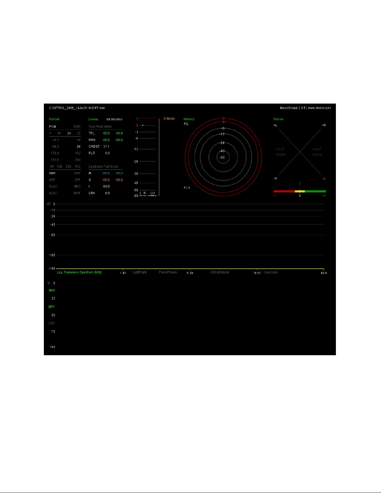
• A typical AC wall outlet (A + A1 Inverted Phase)
The only detectable readings we see above are the self-noise of the
test equipment itself. It’s essentially zero.
This audio sample sounds like nothing because
it’s a sample and second inverted sample of the
studio’s wall power. No difference equals no
audio sample.
3
Page 6
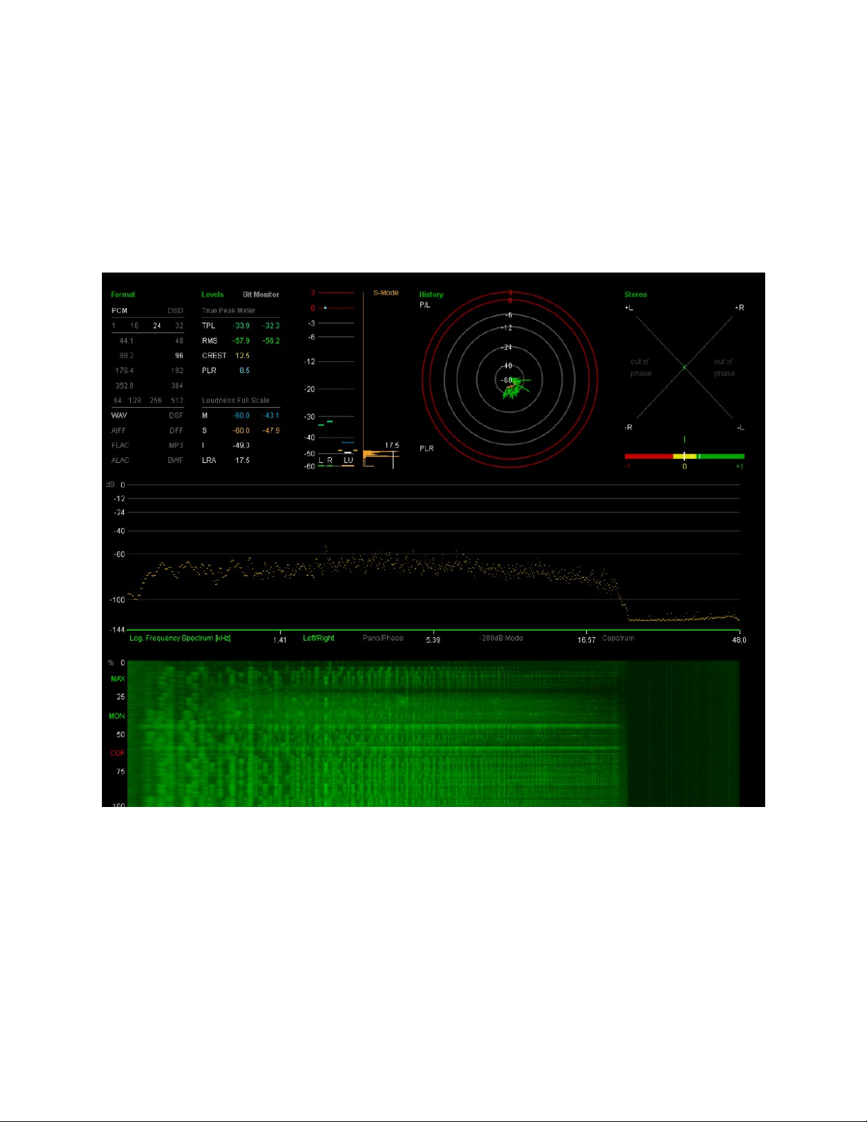
• A well-regarded audiophile power conditioner/regenerator and
their premium AC power cable versus the wall outlet.
(A + B Inverted Phase)
( need text description)
Here we see a considerable difference. These AC power technologies are doing their job, and the signal you see and hear are those
that are lost to signal coupling and masking effects without use of
these AC power solutions.
What you hear is very low in level at times,
because you are hearing the difference. This is
the signal that would be lost without use of this
AC power conditioner and advanced AC cable.
4
Page 7
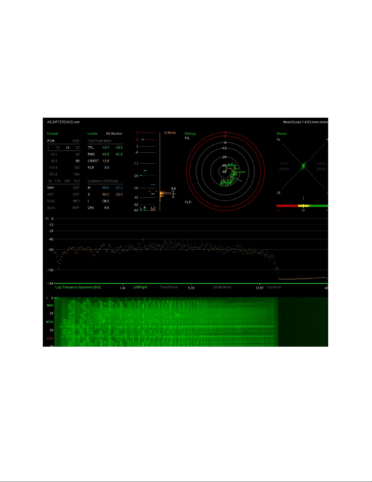
• The Niagara 7000 Low-Z Power Noise-Dissipation System and
Thunder AC power cord versus the wall outlet.
(A + C Inverted Phase)
Here we see a far greater signal difference. This is a more effective
AC power solution.
What you hear seems louder and fuller, because
the AC power technology can preserve far more
information. All audio files are native signal with
zero composition for volume level.
5
Page 8

These analysis charts are taken from the digital audio difference files
for all three test variables (the wall AC outlet A, phase inverted file
A1, and power products B, and C) figure 1. What’s significant about
this type of test versus the noise reduction over frequency (common
mode, ground, or differential mode), surge suppression, or distortion,
is that a difference file is the only one that perfectly tracks what the
product will do in a real-world audio system.
For example, we could take a sampling of 12 AC power products,
and test their noise reduction in a laboratory while feeding them signals from a signal generator at a fixed source and load impedance
(as is typically done). The problem is we can’t know exactly how that
will manifest itself in any audio playback system. There are simply
too many variables. In the same way, comparing the total harmonic
distortion of 12 audio power amplifiers and using that single test result as the only means of comparison would be utterly meaningless.
A digital difference file is unique in this regard. A 10-second sample
from a digital audio file is played through a chain of electronic components that convert digital to analog (as will always be required in
home playback of a digital source), and then it is converted back into
a digital signal and stored on a computer drive. This is done (in this
instance), with all of the system’s components powered from the AC
wall outlets, then powered via an audiophile-grade power regenerator/conditioner and their premium AC power cord, and finally the AudioQuest Niagara 7000 Low-Z Power Noise-Dissipation System with
our Thunder AC power cord.
Next, these digital signals are precisely aligned to the last sample,
beginnings and ends are cropped to start and end at precisely the
same time, and only then the first (control) digital audio file (A) is
matched start to finish with the A1, B, or C sample, one pair at a time.
Samples A1,B, or C are then reversed in polarity as compared with
their control file (A).
If the technology in the given AC power device and cable is not effective, or if the audio or digital component’s power supply is truly capable of eliminating enough RF and electrical noise so that the final
audio signals will be left pristine (unaltered), the result of this reverse
polarity “difference” should be zero. Nothing at all.
6
Page 9

Of course, what you see with any premium AC power device is a
sizeable difference, and with the Niagara Series products we see
even more. This difference is represented as signal. It’s not about
shaping the tonal color of the system or simply creating a mild euphonic effect, rather a substantial quantity of audio signal that will
either be lost or distorted from circuit-coupled noise. Low-level signals are critical to audio reproduction. They contain the majority of
instrument harmonics, the highest frequencies, the leading edge of
most transients, and nearly all of the imaging or spatial information.
These vulnerable signals will remain intact, only if the right AC power
technology is employed.
In fact, if you download this document from our website, you can
hear this for yourself. Bear in mind this is not a short audio clip
of glorious full-fidelity audio. Instead, you are listing to the difference
only. What you are hearing is the signal that would have been lost
forever without the aid of proper AC power regeneration, isolation,
or filtering tech-nology of some sort. The volume is the native
level, nothing was adjusted post production.
Beyond the signal loss and distortion that is due to the ever-present
and increasing noise on the AC line (industrial machinery,
satellite, short wave, AM/FM radio, cell towers, Bluetooth, and
harmonic noise from switch-mode computer power supplies), we
could also investi-gate the fundamentals of alternating current,
Ohm’s law, as well as transient voltage and current spikes that
can damage our sensitive components. However, these topics are
worthy of and would require a book rather than a short pamphlet).
So, for this installment, I will primarily devote the following pages to
a discussion of how various AC power technologies can affect
sound quality. Although the basics of alternating current are well
covered in numerous engineering articles and books, the way in
which many AC noise and power phenomena affect the audio signal
has never been especially well documented.
When examining these phenomena, it’s important to understand
that any honest assessment of electrical circuits and their
implementa-tion will be fraught with compromise. The key to
designing any AC
7
Page 10

power delivery device that will serve a system best is knowing the intended application. It would be unwise to assume that the AC power
technology most appropriate for a factory or broadcast facility is also
ideally suited for a home audio system. Additionally, engineering with
circuit-design dogma is rarely productive (everything has its place
and nearly every idea has some merit). What’s important is to strike
the best overall balance between the various appropriate AC power
technologies, while neither omitting any critical design aspects nor
focusing too much attention on only a few positive attributes.
Detailed below are some of the dominant AC power technologies
used in and outside of our audiophile and A/V industry. I will attempt
to explain their basic working technology, their strengths and weaknesses, and how they will affect a high-resolution audio system.
AC Surge Suppression
The technology associated with AC surge protection was originally
meant to provide a minimal level of protection against catastrophic damage caused by AC voltage and current spikes. The protection circuit or
devices must be adequate to handle up to 6000 volts peak and 3000amp transient current spikes. Any level of power beyond that will not make
it to your system without your building catching on fire and your breaker box
and electrical wiring turning to molten steel, copper, and plastic.
The primary concern is usually either an electrical storm or a damaged
utility power transformer. If the spike is not too severe, it can be absorbed and turned into heat by various means. The most common and
affordable are metal oxide varistors (MOVs). Some circuits employ avalanche diodes, gas discharge tubes, or active switching detector circuits
with line induction and switching transistor relays (SCRs).
There are two basic types of AC protection devices: sacrificial and nonsacrificial. Ideally, the purpose of the sacrificial protection circuit is to
absorb enough of the AC voltage or current spike to save the connected
components and their power supplies from catastrophic damage. At
times, the spike could be so severe that the protection circuit will be
damaged and “give its life” to either save or minimize the damage to the
8
Page 11

connected components (thus, it is sacrificial). These devices are quite
useful in areas where electrical storms are common and the resulting
damage to electronic devices is well known.
Unfortunately, some of these devices do not give a reliable indication of
having been either damaged or destroyed after one or more extreme
power spikes. Further, if the power event is not a fast transient, but a
sustained surge that persists for minutes or hours, most of these circuits
will not only give their lives, but they will then pass the damaging voltage to the power supplies of the connected components. Sadly, many
otherwise premium AC filter-conditioner-regenerators rely on a variant
of this low-cost sacrificial power surge/spike technology.
The other less common power surge/spike technology is non-sacrificial
or non-sacrificial hybrids. In some circles (particularly pro audio/sound
reinforcement), the specifics of these circuits are highly contested, and
considering that the application can be so vulnerable, given outdoor
events with considerable exposure, expense, and risk, it’s understandable that there’s contention about which circuit clamps spikes faster, at
the lowest voltage above RMS, and with the least damage to its own
circuit devices. However, as its name suggests, the whole point of nonsacrificial surge/spike protection is to protect the connected components
without sustaining any damage to itself. That, along with the ability to do
so in the intended application, is what’s paramount.
This technology always requires a passive/active circuit, because
voltage detection of some type is necessary, and it must react in a
fraction of a second to be effective. For example, if a multiphase electrical service, such as those found in every office in
the world (typically three-phase wiring), were to lose its neutral,
and a portion of a system is connected to at least two AC service
outlets from a different phase, then the AC outlet group that draws
the least current will suffer a huge voltage surge. Only an overvoltage shutdown cir-cuit can protect against this, and only a nonsacrificial surge circuit can survive.
Catastrophic failure is only one concern, however. It’s important to
understand that our electrical grid is and always has been optimized
for simple appliances. Many audio components feature robust tran-
9
Page 12

sistors and valves that can withstand electrical spikes as high as 1000
volts, and certainly spikes of 300 to 500 volts peak. However, today’s
audio systems feature many surface-mount electronic devices that
can suffer catastrophic damage with as few as 3 volts across many
of their electrical junctions. They can and will suffer sustained damage from relatively modest electrical spikes that often pass through
our electrical service outlets, can pass through the power supply, or
are transmitted (in part) via AC ground.
Once subjected to years of use without any form of power spike/
surge protection, most of these sensitive circuit chips will not have the
resolution or equivalent noise specifications they originally had. This
is why even in areas with no multi-phase wiring and no incidents of
electrical storms, some sort of AC protection is necessary for DACs,
streamers, universal players, projectors, computers, routers, and a
host of digital components. Remember: Due to the increased masking effect of the low-level audio signal, the more the noise increases,
the less fidelity you can expect.
Despite these power-protection devices having obvious value, sacrificial and non-sacrificial devices alike can create their own distortions
that can play havoc with the low-level audio signals. Most of these
circuits and devices will resonate or ring when subjected even to
small power spikes (which are a constant).
The resultant sound from these circuits can be harsh and strident.
This is due to dynamic intermodulation distortion, as radio frequency
noise couples to the low-level audio signal and the power spikes
modulate a portion of this noise, (at a very fast rate), to audio transients. In other cases, instead of absorbing the noise and turning it
into heat or re-directing the noise to the electrical service or Earth
ground, these protection devices can work as a sort of noise trap,
redirecting ultra-high frequency noises back towards the sensitive
component circuits and ground. Thus, it takes very careful implementation of these protection circuits and devices in order to avoid
creating in the present as much sonic damage as the power spikes
will create later on.
10
Page 13

AC Power Conditioners/LCR Filters
AC power conditioners and/or LCR filters are passive technologies—there is no active switching and no amplification devices are
utilized—and they will typically work over a wide range of conditions
(100-265 VAC / 50-60 Hertz operation) without any conversion or
circuit adaptation. These circuits are often combinations of three
passive devices, represented by the letters LCR, where “L” is inductance, “C” is capacitance, and “R” is resistance. Any combination of
these devices can be utilized to filter and to a degree convert unwanted RF and electrical noise into heat.
There are two types of noise that appear on AC Line, Neutral, and
Ground leads: symmetrical noise (referred to as common-mode) and
asymmetrical noise (referred to as differential or transverse-mode).
Most differential noise is already present on the utility AC line or is
backwashed via a home or office’s electronic appliances and components. On the other hand, common-mode noise is typically picked
up by AC Line, Neutral, and Ground leads like an antenna. These
RF noises (radio frequency signals) are generated from cell towers,
satellites, AM/FM, Bluetooth, and shortwave.
Some of these filters are limited to covering differential noise, some to
common-mode, while other designs cover both. Their effective range
or bandwidth can vary considerably. There are at least 23 octaves
of measureable noise on the AC line from mid-audio frequencies,
up to the carrier frequencies of a cell tower (kilohertz to gigahertz).
Unfortunately, it’s costly and takes considerable space to adequately
cover all of the AC and RF noise that will affect (distort) audio systems’ low-level audio signals.
Further, many of these circuits are designed and tested for theoretical laboratory conditions (matched impedance – typically 50 ohms
source and load), as this is what most power filter mathematics are
based on. This measuring convention goes back 80 to 90 years, is
entirely based on convenience, and it’s absolutely wrong—a source
impedance of 50 ohms at 100-260VAC 50/60Hz would represent a
severe brown out/voltage sag. In reality, the source impedance is
a fraction of an ohm at AC powers rated RMS frequency, but, due
11
Page 14

to line induction, it raises considerably with frequency. The load impedance is subject to the same electrical conditions, but the current
load is in parallel, and that becomes the overriding impedance. Since
power amplifiers feature dynamic current, the impedance is variable
with frequency. This is a problem with passive filters if they are not
both tested and electrically damped for real-world impedance (and
most are not…).
There is an additional problem: In order to cover enough range, a
passive filter will require some inductance (the “L” in LCR), which will
raise the AC impedance somewhat and create a phase lag for power
current transients. This is of no consequence to video, computer, or
source audio components, as they utilize low-amperage constantcurrent circuits. However, this can severely current compress a power amplifier as its power supply draws down to supply an audio transient, while the power amplifier itself requires a large influx of current
to its power supply to maintain low-distortion operation.
To get around this issue, many passive AC power filter/conditioners
will isolate the circuits that utilize any series inductance for source
components only. The circuit without series inductance is set aside
for the “High Current” power amplifier outlets. If a power amplifier experiences current compression, the sound that results from an audio
system can be described as thin, anemic, muddy, and slow, while the
soundstage tends to collapse or pull with frequency during dense or
modulated passages.
12
If the AC filter or conditioner does not cover sufficient octaves or
range of noise filtering, or does so unevenly (due in part to resonance-peaking problems associated with either no or improper impedance compensation), the resulting sound for the low-level audio
signals will be akin to re-voicing a system. This discordant sound is in
the critical range of most instrument harmonics, and the tonality will
continuously change as the music’s volume, transient/dynamic content, and frequencies modulate second by second, minute by minute. Essentially, this creates a mess of the most prized portion of the
audio signal. You do not want one octave unveiled from the distortion
and signal-cancelling effects of noise-masking, only to experience a
resonant peak that creates even greater distortion and masking a
Page 15

quarter octave away.
The advantage (particularly for differential AC and RF noise) of a welldesigned impedance-compensated LCR filter is that it can be manufactured to handle vast levels of current without saturation or clipping, and,
if properly executed, it can maintain at least some of its filtering capabilities for many octaves beyond any other circuit or design.
AC Regeneration
An AC regenerator is essentially an AC power amplifier. It works by converting AC power from your utility tap, converting that into DC (Direct
Current; like a battery), and then regenerating a precise AC sine wave
for a determined RMS current. When measured below its power capacity threshold, a successful AC regenerator produces a very clean sine
wave; in fact, the sine wave from such a device can be made to be extremely low in harmonic distortion (i.e., nearly perfect).
Because the generated sine wave is so pure, magnetostriction and
the associated mechanical buzzing caused by interaction between
power supply transformers and extraordinarily high quantities of harmonic distortion on the AC line is eliminated. (For more on magnetostriction, see “DC Blocking Devices for AC Power.”) In addition,
a pure and unwavering, frequency-locked sine wave will enable far
greater speed stability from turntables with AC synchronous motors
(like many from the 1970s).
On the surface, it seems that AC regeneration would be the ideal AC
power technology to pursue. However, once we understand the rest
of the system, its circuitry requirements, and how AC and RF noise
are manifested into an audio system, we realize there’s more work
to be done. First, 99.9% of audio components feature either linear or
switching power supplies that will accept an AC sine wave with as
much as 25% harmonic distortion (an extraordinarily high amount),
and convert that via rectification into a Direct Current power supply
with essentially zero harmonic distortion. In other words, this regeneration technology renders a nearly perfect sine wave for circuits that
do not require or benefit from it at all.
13
Page 16

Furthermore, an AC regeneration amplifier is potentially large, heavy,
and, if it has sufficient power capacity for an audio system, it will generate a significant amount of heat. Amperage times voltage equal
watts (and you’ll need a lot). A regeneration device such as this that
could supply 10 to 20 amps RMS at 100-250VAC will be costly, large,
and create considerable heat (relative to its class of operation).
Current compression is a real concern here, as the AC regeneration
circuit will raise impedance compared with even modest AC service
taps. But also bear in mind that this is an AC power amplifier: Amplifiers have a given RMS power capacity—typically about 40-50%
above the rated RMS power—before their output distortion eventually runs into severe clipping. Thus, even a massive 20-amp RMSrated AC regeneration amplifier will likely suffer severe clipping by
30 amps peak. A well-designed passive filter with series inductors
will only start to soft compress by 50 amps peak, and many audio
power amplifiers will require instantaneous peak current as high as
70 amps peak or greater. During the reproduction of bass passages
and audio transients, this current compression results in sound that
is hard, grainy, thin, and/or weak—just as any power amplifier would
sound while suffering through severe clipping.
The other issue is AC noise reduction. This is vital—not only for an
audio power amplifier, but for all source components. The differentialmode (Line and Neutral leads only in this application) and commonmode noise reduction of such a design is quite good. Ground noise is
typically not addressed at all unfortunately, but common-mode noise
reduction is spectacular within its frequency bandwidth (nearly 100
decibels)! The problem is that this noise reduction all but ends when
the amplifier runs out of bandwidth—anywhere from 10kHz up to a
hard limit of 200kHz.
Once this bandwidth is exceeded, the noise rises dramatically as
there is no active circuit remaining to reduce or cancel it, and nearly
all RF noise is well above this frequency cut-off point, making this circuit less than ideal for filtering the vast majority of AC and RF noise.
Further, the transition from -100dB to 0dB creates ringing patterns
that can have audible consequences for octaves below.
14
Page 17

In short, this is the ideal solution for an AC motor, but a questionable
one for an audio component.
AC Isolation Transformers
This technology utilizes an AC transformer with close to a 1:1 inputto-output ratio (i.e., the input voltage is typically about the same as
the output voltage). Regardless of the transformer’s shape (toroid, EI,
C-core, or other variants), they are meant to isolate common-mode
noise from the AC service line, which is accomplished by blocking
and draining as much of the RF noise as possible. In order to block
the noise, a Faraday shield must be implemented between the primary and secondary (input and output) windings. In order to drain
as much of the RF noise to a lower impedance path and away from
the transformer’s output, the shield is then connected to a grounding
circuit. Otherwise, RF noise could couple to the transformer’s output
by jumping across the primary to secondary windings, capacitively,
from the input to the output.
There are many techniques involved in manufacturing these
shields, and many others involved in the transformer core and
windings topology. All have an effect on the amount of noise that
can be diverted or turned into heat, and, as the noise present on an
audio component’s AC inlets is reduced, masking effect and distortion are also reduced. More resolution, better sound. The lack of
this very necessary shield is one reason even the finest linear
power supplies used in many premium audio components cannot filter or divert as much RF and electrical noise as an external AC isolation transformer.
Additionally, due to layers of small-diameter windings, the audio
component’s transformer will usually include far greater distributed
capacitance. Reduced size is often required by audio component
transformers to satisfy chassis limitations and circuit demands, as
these transformers must accommodate a number of output voltage
taps for various DC power supplies. This can pass and even create
non-linear distortion of the ever-present RF and AC noise. Different
applications require different techniques.
15
Page 18

Some AC isolation transformers feature symmetrical (center-tapped)
or balanced outputs, while others do not. An argument can be made
for a host of winding techniques, but so long as the isolation transformer has a faraday shield and grounding drain, it can filter or divert
a considerable amount of RF and AC electrical noise that is common-mode (symmetrical) in origin. This noise dissipation technique
is effective over many octaves from the audio passband well into
radio frequency bandwidth.
Some exotic designs can also reduce differential-mode (asymmetrical) noise, but never linearly or consistently, and not over many octaves. So, for differential AC noise reduction, it is typically necessary
to utilize a wide-bandwidth linearized differential filter in series with
the isolation transformer, or half the noise will remain to pass through
to sensitive audio components.
It is also important to consider the output impedance of any AC isolation transformer. This is widely misunderstood. Some designers and
manufacturers have attempted to make the case that so long as the
transformer has good regulation (there is minimal voltage drop at
full-rated RMS current), is physically large with great current capacity
(say around 2400VA; nearly 20 amps @ 120V or 10A @ 240V), and
the windings feature large winding wire leads, then the transformer
will be suitable for an audio power amplifier. The problem is that the
large winding leads only affect the DC resistance, but not AC impedance. Also, even though great regulation and a large VA rating are
important, the fact remains that this is an inductive device. As such,
it will create a phase lag for any AC current transient, raise the AC
impedance, and thus current compress the power amplifier.
16
In fact, the AC isolation transformer could be the size of your sound
room, and, by definition, it will raise AC impedance. This leads to
slower audio transients, muddy less-defined bass, and, when this
technology is used for power amplifiers, collapsed soundstaging for
complex modulated audio passages.
Again, for reducing common-mode (symmetrical) AC and RF noise
over many octaves as linearly as possible, an isolation transformer is
the gold standard. For differential-mode (asymmetrical) AC noise, it’s
Page 19

less than ideal and will not be linear (consistent over many octaves).
Without the aid of a properly designed impedance-compensated differential AC filter, this can create inconsistent sonic results from harmonic to harmonic, octave by octave, as the noise-masking effect
is not reduced in a thorough and predictable manner. For a power
amplifier, it’s a source of current compression. So, ideally, it would
be utilized for common-mode AC power and RF noise dissipation for
source components only.
DC Battery Isolation Devices with AC Inverters or
AC Regeneration Amplifiers
DC battery isolation devices with AC inverters or AC regeneration
amplifiers tend to stress the advantage of allowing a system to be
utilized “off the grid.” Given the horrendous effects of AC and RF
noise, this would seem ideal. In the past, the problem with such a
system was that the older lead acid batteries were weak, simply lacking the capacity required for even a modest audio or A/V system to
run for more than minutes at a time. A new generation of batteries
has changed this, and it is now possible—for a price and with considerable weight—to run even an ambitious audiophile system for a few
hours before recharging is required. That is, assuming cost is no object, and you have room for such a device. Unfortunately, however,
there are some pitfalls.
These designs do not address AC ground noise, and for reasons of
safety, electrical codes, and the need of many components to have
a hard AC ground reference for both RF noise draining as well as to
eliminate hum, this technology isn’t really “off the grid” (nor should
it be). The other problem is that our A/V components do not accept
DC power as their input to their power supplies; they require AC (alternating current). So, the massive state-of–the-art battery is always
followed in circuit by an inverter or AC regeneration amplifier. (Read
“AC Regeneration” to learn what will happen there!) Further, some
of these systems can supply up to 30 amps RMS. That’s wonderful
where current capacity is concerned, but it means the unit will be
a space heater that will require mounting in another room or utility
closet and/or a very serious air-conditioner. A simple inverter will run
17
Page 20

cooler than the regeneration amplifier, but it will do next to nothing for
linear AC and RF noise dissipation beyond haphazard, unpredictable
loss from the circuit parts.
Any AC power device that must be operated at a considerable distance away from audio system components is at a serious disadvantage because long AC cords are carriers of induced RF noise. Ideally, the AC power solution (be it a filter, regenerator, transformer, or
other) needs to be as close to the system components as possible,
with the shortest runs of AC cords.
Consider the carrier frequency of Bluetooth (2.4GHz). That RF noiseinducing sine wave is so small you could place a half-dozen of them
end to end and easily fit them on the edge of a piece of paper! To the
radio frequency noises that can be induced into the cable after the
AC filter, even a modest 2-meter AC cord might as well be a kilometer in length. This is one reason why premium AC cables can actually
have a great impact on a premium system if they address RF noise
dissipation, and do so as linearly as possible.
AC UPS Battery Backup Devices
UPS battery backup devices are compact versions of the “DC Battery isolation devices with AC inverters” described previously, except
they are typically smaller, rack mountable, and rarely feature enough
current capacity for even a modest audio system. Their intended
application is emergency backup of the most vulnerable servers,
drives, NAS devices, routers, and other computer peripherals. Some
video projectors are also vulnerable if a power blackout occurs, in
that they would not have sufficient power to cool the lighting circuit
before damage occurred.
Some of these units include some surge protection and filtering, but
it’s rarely adequate for premium audio. Most of these devices fit into
the category of Sounding Far Worse Than the AC Service Outlet,
and, at best, the expense has been weighted towards minutes of
backup rather than system performance and resolution.
18
Page 21

AC Voltage Regulators
A voltage regulator simply adjusts or compensates for the incoming
AC voltage, and supplies a steady, predictable output voltage for the
system components. Some of the very best voltage regulators are
actually not referred to as such. In fact, AC regeneration amplifiers
are the very best regulators, as the output voltage is typically within
a fraction of a volt of whatever the chosen output voltage is set to.
However, if high current capacity is required, these systems tend to
be too costly, quite large, and they produce considerable heat.
The alternative (with slightly less output voltage precision) would
be either a motorized Variac system or a switching auto-former
device. The motorized Variac is a series transformer (called an
auto-former) with shaved windings on top of a toroidal core. A toroid transformer or series auto-former is a doughnut-shaped core
with electrical windings that pass through the hole and around the
outside of the circular form. Since these large winding leads are
shaved on the upper surface, it’s possible for a large motorized
arm (pivoted from the center of the auto-former), to move across
these windings until a voltage detector/comparator circuit finds
the correct tap for the ideal set output voltage. This is still used for
some professional sound reinforcement at outdoor festivals, but,
besides being a low-fidelity, high-impedance power device, the
sparks that fly as the arm’s electrical brush attempts (second by
second) to find the correct voltage tap creates considerable noise.
For high-resolution audio, avoid at all cost!
The other means is similar, but the auto-former has no exposed windings. Instead it has a number of leads (voltage taps), and these are
connected to a high-power, low-impedance circuit that uses either
relays or solid-state relays (triacs) to switch to the appropriate output
voltage tap. This method is best when the units must run reasonably
cool, space is limited, and current capacity must be high.
The problem is that all of these AC voltage-regulating technologies
raise the source or service AC impedance significantly. That’s acceptable in a live sound reinforcement setting with limited fidelity,
highly compressed audio, and a crowd that’s providing a noise floor
19
Page 22

above 90 decibels. The other issue is that all AC voltage regulators
create varying degrees of noise, which defeats what is most required
to gain greater fidelity and resolution from your system.
Granted, some may live in areas where the AC voltage is routinely
so low they risk the system shutting down, but that is the exception.
Further, modern power supply designs in system components typically have the means to adjust for these issues far more effectively
(either with DC regulation or with switching power supplies).
For all but the direst circumstances, this is a technology that audiophiles would do well to avoid. From the lowest frequencies to the
highest, the majority of these devices will likely lose (sonically) to the
standard AC service tap.
DC Blocking Devices for AC Power
As was previously described in a portion of our text titled “AC Regeneration,” there can be an issue with extraordinarily high levels of
harmonic distortion on the AC line, or back-feed from a component
or electrical appliance. When it reaches a high enough level, this distortion is largely responsible for the mechanical buzzing or hum from
some linear power supplies (specifically, their transformer cores).
However, the same problem can be created by a similar phenomenon, which is direct current (DC) that is present on the AC line. This
is rare, and ideally there would never be any direct current modulating an AC service tap. Unfortunately, some homes or neighborhoods can have pool motor controllers, table saws, electric potting
wheels and other machines that require considerable current, and
whose control circuits utilize poorly made half-wave rectified power
supplies. These cheap circuits may be fine for simple machines and
appliances, but they can create a DC voltage-current that, though
modest (typically under 2 VDC), can really play havoc with the core
of an AC power transformer.
20
This is the magnetostriction we discussed previously. As the core
of the transformer attempts to turn this distortion into heat, the core
vibrating against the transformer windings can actually sound some-
Page 23

what like a door buzzer, and can be quite annoying. If the cause
of this magnetostriction is in fact a residual DC modulating the AC
power, a series capacitive blocking device can be quite effective in
reducing or eliminating this troublesome buzzing.
Many of these devices have been sold as accessories with the claim
that, if not addressed, the residual DC will do audible harm to the
system’s components. In reality, any system that is not plagued with
high levels of mechanical transformer buzzing will not likely have any
real benefit, because the component power supply will convert all of
the AC power into DC within its power supply anyway. Audio, video,
and digital electronic circuits utilize DC (direct current), not AC for
their circuits.
This is not to say that installing a DC blocking circuit will not “make
an audible difference.” With high-resolution audio, nearly everything
makes some kind of a difference. The reality though, is that the difference is likely due to the unintended consequences of the additional
connectors, AC cords, and their effect on RF noise dissipation or the
line impedance (be they good or bad).
Harmonic Oscillators for AC Power
When it comes to harmonic oscillators for AC power, my background
in engineering tends to show a little bias. I would like to think I could
embrace every idea equally, but some things are more challenging
than others, particularly when the manufactures can only provide
scant theories and references to quantum physics to explain what
should really be simple electrical phenomena. Yes, there are and
always will be things we do not understand, and a real engineer or
scientist must put aside prejudice and attempt to study these ideas to
understand what effects they have and why—and not simply dismiss
what’s intellectually inconvenient.
It is in this regard that I have worked to understand and learn all that
I can from ideas that have been presented (notably to) the audiophile
marketplace of ideas. Essentially, this circuit typically utilizes a basic
AC filter or even simpler power distribution box, which is placed in
21
Page 24

close proximity to one or more oscillator circuits. Quartz crystals and
other devices may be used, but essentially these circuits radiate considerable RF noise or energy for a short distance from their circuit.
This is precisely the opposite of what most component electronic
engineers strive to achieve, as we do not wish to make RF noise and
its distorting and masking effects even worse.
In many situations, this is something that would not only be undesirable,
but would fail North American FCC or European IEC radiated high-frequency noise requirements or standards. Let’s put that aside for now,
since many audiophiles would be quite willing to try a technology that
isn’t necessarily within the technical norms of other industry electronic
devices. Additionally, these radiating oscillators do not have enough
range or power to do any harm to life support or other critical devices.
What’s intriguing is that, in many cases, these circuits can make a subtle
but small improvement in some audio systems.
The reason is that just as governments and their militaries have used
radio-blocking signals for decades, it is possible to block some radiating RF that would couple to your system’s AC line (masking and
distorting low-level audio signals). The issue with this technology is
how unpredictable and inefficient the methodology is. In the case
of spy agencies and military engineers, all they need to do is to determine the carrier frequency (or frequencies) in question and then
adjust a circuit to counter (block) it.
22
That’s not easy or cheap to do well, but it can work. The problem with
AC noise, is that this will do nothing about the noise that is already on
the line: it can only effect the RF noise that is attempting to couple to
it like an antenna. This system is miserably non-linear (inconsistent,
uneven), and cannot cover many octaves.
When compared to the standard AC service tap, the sonic outcome
is (sometimes) less grain or distortion, but the RF noise reduction is
so uneven that audio transients tend to pull with frequency as the
phase relationship of very low-level signals is alternately unmasked
and then distorted in quick succession. Instrument location in space
tends to be unfocused and oversized, potentially creating a “fun
house mirror effect.”
Page 25

AC Resonance/Vibration Dampening
Again, everything in high-resolution audio counts. Everything makes
a difference. However, a common problem in the audiophile community is placing the greatest share of attention or care to an area
that is responsible for contributing a mere 0.001% to any sonic consequences.
Obviously, we know that resonance within critical audio circuits is an
important topic, and this is a known science. The lower the signal level is, the greater the chance of distorting the audio content. If we examine a low-output moving-coil phono cartridge, for example, we are
already starting with a signal that is at least 60 to 80 decibels below
the output of the power amplifier. Subtract from that a potential 70 to
80 decibel dynamic range, and the circuit will need to be stable and
unconditionally quiet down to a fraction of a microvolt. Sadly, that’s
not always possible. So, anything we can do to lower electrical noise,
including the effects of mechanical noise and vibration, will help.
However, AC power is already at a decibel level decades higher than
most audio signals. Further, we are not trying to faithfully reproduce
low-level signals below the AC power’s sine wave. (That would be
noise and we’re trying to eliminate that.) Yes, AC power has vibration
you can actually feel since it’s an alternating 50- to 60-cycle waveform with considerable current to feed power amplifiers. However,
the alternating current is immediately converted to vibration-free DC
(direct current) in the system components’ power supply.
It’s not that a well-designed platform for a power component isn’t a
worthwhile investment, but a power device whose design budget has
been entirely or mostly invested into the proposition that vibration
is the most significant issue facing power is simply misguided. If an
AC cord of 10 meters length were cemented into a ton of bedrock, it
could be easily measured that 99.999% of the noise that was present
at the input would still be present at the output (in addition to the RF
noise induced along the way).
23
Page 26

Power Correction for AC Power
Power correction for AC power is a variation on an 80-year-old technology termed AC power factor correction. Many factories ran multiple motorized machines, which created such a large inductive load
that they did two very bad things to the AC service supplied by their
power utility: The first problem was that the voltage would often be at
or below the bottom AC voltage threshold required by the machines
or other appliances to run efficiently, or at all—a considerable voltage sag could occur. The second issue was that the phase angle of
the sine wave was severely distorted, and this also meant nothing
ran very well. This could also be costly, as, due to increased loss,
the perceived kilowatt/hours would read higher than they would otherwise. The solution was for an engineer to measure the electrical
load, and to utilize a high-power, high-current AC capacitive parallel
circuit that would both create the proper phase angle for the sine
wave (which returned the AC voltage to an ideal level), and, as the
machines now ran more efficiently, save expense by reducing kilowatt/hour consumption.
This technology, however, is not well suited to an audiophile system. It’s massive, heavy, acoustically noisy, and requires the RMS
(average) current load to be constant. That can never be true for
the greatest recipient of AC current in an audio system—the power
amplifier. This current draw will vary with audio signal and volume
levels, so there’s no possible way to make a mathematical model
that could work for that application. However, there is virtually no
power amplifier manufactured for an audiophile or home theater that
would ever have an issue supplying a clean sine wave signal, which
demands an easily supplied RMS current draw. Source components
have a constant current draw, and the draw is quite low as well, so
there is no problem with power factor.
For our application, the issue is the current transient. This is because even a large 2000-watt monoblock class A/B-1 power amplifier will likely never draw more than 5 to 6 amps from the wall’s
AC service tap for music signals (RMS, average). It’s the fast audio transient that creates the problem, and the effect that is called
“current compression.”
24
Page 27

When the amplifier’s power supply is required to release joules of energy to supply its amplification circuits with the necessary power for
an audio transient’s massive peak-to-peak voltage swing, the condensers in the power supply are acting as a type of charge pump that
has just been driven from a fraction-of-an-ohm impedance to nearly
zero. Granted, this occurs only for a brief moment (say 10ms). This
ultra-low impedance appears to the supply transformer (be it in the
chassis or supplying your building) like an intermittent short to which
it must supply current. This is a potentially unstable condition, where
even a modest power amplifier can require an instantaneous draw of
over 50 amps peak. If the AC current supplied to the power amplifier
is impeded in any way, or not adequately buffered with low transient
impedance, it will suffer current compression.
This is why power amplifiers always perform best with an AC service
tap that has a current rating many times higher than the RMS draw
of the circuit itself. The advantage of Transient Power Correction is
that it does not rely on a steady load, and only briefly responds to
the current transient (which is what an audiophile power amplifier
needs). These circuits can actually lower that transient impedance,
buffer the amplifiers’ power supply, and deliver a current reservoir in
excess of 40 to 90 amps peak. Essentially, for an audio transient, it’s
akin to a short connection to your utilities substation with a 60 to 80
amp discrete service to each amplifier.
The Transient Power Correction circuit is difficult to manufacture. It is
also critical to ensure that the circuit is not creating resonant peaking
in an AC linear filter. The device must also be acoustically quiet, as
it will absorb a great deal of harmonic distortion on the AC line and
attempt to turn that into heat. It also creates a vector load that is confusing to some electronic technicians: When they troubleshoot, they
might fall under the impression that the power product is consuming
more RMS current that it actually is.
When this circuit is properly utilized, however, more dynamic range,
control, and bass extension can be realized.
25
Page 28

Ground Noise Dissipation for AC Power
Sadly, about a third of the differential-mode (asymmetrical) noise and
some common-mode noise can be found on the AC ground lead.
Because the electrical service counts on this redundant electrical
lead primarily for safety (even though the audio industry relies on it
for far more), there are very few things that can be done to reduce
ground noise effectively and legally. There are some minor inductive
mesh-traps, beads, and clamps, that are used, but these are far from
linear, and most do very little. What’s even more troublesome about
the AC ground lead is that many audio circuits depend on it to ensure
there will be an electrical ground reference to minimize system hum.
Others also rely upon it to drain as much RF noise from their circuits
as possible.
In comparison with the Line and Neutral leads, the significant attribute of the AC ground lead is that it bypasses the component power
supply and makes a direct connection to most of the critical audio
and digital circuits bringing a torrent of noise along with it.
Because of the impedances involved across a vast multi-octave array of RF noise, it is actually quite difficult to do anything about this
without creating a mess, or at best, mixed results. The noise currents that appear on AC ground will always follow the path of least
resistance, but oftentimes that can end up leading to the audio or
A/V component’s chassis and circuitry (instead of the AC power filter/
conditioner/regenerator/isolation system). If this is not handled correctly, it’s far worse than if you’d done nothing at all, leading to grainy
sound or even oscillation with some exotic circuits. Eliminating the
AC ground lead (as has been a trend in years past) is rarely the
answer either, as many circuits rely on an AC ground reference to
function at their best.
This is a subject I have spent most of my life studying, with over
20 years in the AC power field, developing products for audiophiles,
professional audio, and broadcast. It was only relatively recently that
I was able to crack the problem to my satisfaction, and AudioQuest
has patented the solution.
26
Page 29

When successfully utilized, Ground Noise Dissipation for AC power
enables less grain, more signal, more air, and more dimensionality
because a large contributor to the AC and RF noise masking effects
has been reduced and controlled.
Appendix: Some Practical Matters to Bear in Mind
I. Source Component and Power Amplifier Current Draw
How much current capacity does an AC power service or (power filter/
conditioner/regenerator/isolator) require for an audio/video system?
There are many myths and some disagreement where this is concerned. If you use the AC service tap from your utility, many power
amplifier manufacturers will recommend a dedicated 20-amp outlet
(North America 120V) or 16 amps (220-250V). The amplifier will never draw this much current with music signals (even with inefficient
loudspeakers). However, because of current compression concerns,
they are counting on an AC outlet with as little DC resistance as possible, and as little shared load as possible.
The problem with this in many systems, or with the power distribution
products as I’ve listed, is that, as the number of discrete dedicated
AC lines used for a system increases, the further one veers from a
single-point AC ground reference and a bad hum from ground current loops may occur. One important technique for those with either
split-load (North American homes) or a professional building (threephase service; most of the world) is to make certain that all audio/
video AC service taps are on the same phase! You will need to work
with your electrician to have that wired to your AC outlets or confirm
that is already the case. The voltage differential (difference) Line to
Neutral and Neutral to AC Ground will vary substantially (phase to
phase) at the service panel, so the likelihood of hum from a ground
loop increases dramatically in that scenario.
With an AC power product of sufficiently low impedance (such as
those with transient power correction), it is advantageous and quite
possible to combine more than one power amplifier in the same circuit (even with the largest monoblock power amplifiers).
27
Page 30

Although not precise, here is a rule of thumb for calculating the average (RMS) current your system will draw, and the capacity you will
require for a wall service tap or an AC power product. The source
components, computer components, and video components are all
constant-current devices. So, if you look at the specification page of
your products’ service manual (typically available online from most
manufacturers’ websites), you will find total power consumption at
the rated incoming AC voltage.
If the specification were to say: 240VAC input/120 watts consumption (which is equivalent to 0.5 amps draw), the calculation is: Watts
divided by Voltage = Current (amperage). That is, 120 divided by 240
= 0.5 amps.
Most AC power devices and your AC service taps are calculated in
amperes, so this is what you’ll need. If the specification we just calculated is a source component, then the amperage will not vary, that
is simply added to the other source components that will be connected to the same AC power device or service tap. If we are looking
at a power amplifier, we are typically going to experience a dynamic
current draw, and that must be calculated.
To start, we will go to the specification page and make the exact
same calculation:
Let’s say it states: 120VAC input/2000 watts consumption. That
would be 16.67 amps draw (2000 divided by 120 = 16.67)—a sizeable amount!
However, that’s into a laboratory resistive load, and that’s not what
you’ll experience at home. If the power amplifier is truly a class A operation circuit (not mostly class A), nearly 17.0 amps is its actual current draw even at idle. (You have a nice space heater on your hands,
but it likely sounds wonderful.) However, 90% of power amplifiers are
class AB-1 or greater, and for those, you take the laboratory current
specification and divide by three: 16.67 divided by 3 = 5.56 amps.
That’s the real RMS current draw you will likely experience even at
high volume levels.
28
Page 31

If we are investigating a very efficient power amplifier (Class D, digital switching types), such as are commonly found in subwoofers,
divide by 4: 16.67 divided by 4 = 4.17 amps.
Always leave some headroom. If you have a 16-amp service, you
would ideally have at least 10 to 15% headroom above the added
total of all the component amperage calculations. So, for 16 amps,
our upper threshold would ideally be about 13 to 14 amps total.
II. AC Polarity
In recent years, AC polarity has not been much of a concern for most
audiophiles, as manufacturers of component power supplies have
long since learned to measure for leakage currents and make certain that their captive AC cords, AC inlets, and any power supply
transformer is in proper or ideal polarity for the lowest possible noise
measurement (and thus the best sound under operating conditions).
Unfortunately, there is one exception to this: the non-polarized
Schuko outlet and plug that is used by most (though not all) of Europe
and Russia. Because some wiring (such as that used in commercial
buildings) is three phase, and homes use single-phase wiring, combined with electrical wiring standards that have changed over the
years, even a polarity checker is no assurance that you are correct.
There will always be one position with less current leakage from
the component power supply, or greater immunity from AC and RF
noise. The only way to determine this safely, without attempting to
use a multi-meter from a single AC outlet, is to listen.
Use a small adhesive sticker, or a felt tip pen whose ink can be removed with isopropyl alcohol at a later date, and mark the plug and
the socket so that you have a reference point. Start with the first cord
that comes from the service tap, and then, one at a time, try each
cord that is attached to a component.
If your system has a good deal of gain (such as phono preamplifiers),
without any signal present, simply turn every volume to the highest
possible setting and listen for the position with the least noise or hiss.
If this proves too difficult, simply listen to an acoustic audio track that
29
Page 32

you trust. The polarity position with the greatest resolution and the
least edge and grain is the correct one. Mark it, and go to the next
cord until you’ve made certain they are all in correct polarity. During
the listening test, be sure to swap the polarity on a phono preamp
while listening to phono, not a digital source or vice versa, as that
could render mixed results.
III. Over-voltage and Under-voltage Conditions
Over-voltage (particularly from intermittent or open AC neutral) was
covered in “AC Surge Suppression,” but it bears repeating.
If a multi-phase electrical service, such as those found in every office in
the world (typically three-phase wiring or split-load found in North American households), were to lose their neutral, and a portion of a system is
connected to at least two AC service outlets from a different phase, then
the AC outlet group that draws the least current will suffer a huge voltage surge. Only an over-voltage shutdown circuit can protect against
this, and only a non-sacrificial surge circuit can survive.
In short, if this occurs (and it happens every day across the world),
you will lose typical AC surge devices. Seconds later, you will lose
most of the connected components, as the incoming voltage will be
above the power supplies’ maximum allowable range and the voltage surge could sustain for many minutes or hours until the service
breaker outlet trips.
30
If this condition occurs, an automatic active circuit removes the AC
power from all outlets. Do not assume that even costly AC power
products have an over-voltage shutdown circuit. Many do not.
Under-voltage can also be an issue. There have even been some articles touting that under-voltage is more damaging than over-voltage.
Let’s examine that.
Place 700 VAC into any audio component’s power supply and observe what occurs. (I smell smoke.) Now let’s take an identical component and feed it half of its rated input AC voltage. What happens?
Most likely, it will not engage or turn on. If the voltage is reduced from
Page 33

the optimal rating to half voltage, it will likely turn itself off or go into
a protection mode. Yes, there are instances where the life of a part
(such as an output valve/tube) might suffer a lower life as the heater
voltage is too low, but that’s rare.
The real (and only) reason AC brown-outs or severe under-voltage
conditions are dangerous is as follows: If the AC service is at a third
or half of its typically rated power, it is usually due to a down (damaged) mains transformer in your neighborhood or the local substation. That in itself is okay until the problem is fixed. Once that occurs, a massive voltage spike is immediately released, and, without
a fast over-voltage shutdown circuit, your system is in jeopardy. With
a well-designed, quick over-voltage protection circuit, your components are safe and secure.
31
Page 34

Index
AC inverters p.17-18
AC isolation transformers p.15-17
AC Line, Neutral, & Ground leads p.11-12
AC polarity p.29-30
AC power conditioners/LCR filters p.11-12
AC power factor correction p.24-25
AC regeneration p.13-14, 17-20
AC resonance/vibration dampening p.23
AC surge suppression p.6, 8, 30
AC UPS battery-backup devices p.18
AC voltage regulators p.19-20
Ampere calculations p.28
Capacitance p.11-13
Catastrophic damage p.8-10
Common-mode noise p.11-17, 26
Constant current draw p.24, 27-29
Current compression p.12-17, 24-25, 27
Current spikes p.7-8
DC battery isolation devices p.17-18
Differential-mode noise p.6, 11-17, 26-27
Dynamic current draw p.12, 28
Ground noise dissipation p.26-27
Harmonic oscillators p.21-22
Inductance p.11-12
Intermodulation distortion p.10
Magnetosctriction p.13, 20-21
Metal oxide varistors p.8-10
Non-sacrificial protection p.8-10, 30
Over-voltage conditions p.9, 30-31
Power amplifier current draw p.24, 27-30
Power correction p.24-30
Radio frequency interference p.2, 6, 10-11, 13-18,
21-23, 26-29
Resistance p.11-13, 16, 26-27
Sacrificial protection p.8-10
Source component power draw p.12, 24, 27-29
Sustained surge p.9-10
Transient Power Correction p.25-27
Under-voltage conditions p.30-31
32
Page 35

AC difference file test equipment:
The Difference test was performed at Bernie Grundman Mastering –
Hollywood, California, U.S.A.
C.D. (Redbook standard) is Al DiMeola, Paco deLucia, John
McLaughlin “Friday Night in San Francisco” Columbia CK 65168
(track one–Mediterranean Sundance).
CD transport DAC – Aesthetix – Romulus Eclipse (balanced analog
output)
A/D convertor – Lavry-122-96 Mk.II
Audio Card - RME - AES 32
Software – WaveLab 8 – Windows 7 Pro - 64 bit
Tests performed at Bernie Grundman’s personal mastering suite by
Scott Sedillo
33
Page 36

For more information visit our website at www.audioquest.com
or contact us at info@audioquest.com
 Loading...