


TABLE OF CONTENTS
INTRODUCTION……………………………………………………………………………………….3 M-27 SIMPLIFIED OPERATING INSTRUCTIONS…………………………….…………………..5 Control Keys…………………………………………………………………………..……..5 Sound Level Meter Keys……………………………………………….…………………..6 Dosimeter Keys………………………………………………………………………….…..6 Time Keys……………………………………………………………………………………..7 Event Keys……………………………………………………………………………………7 Procedure to Accumulate Event Data…………………………..……………………….7 Setting the Clock……………………………………………………………..……………..8 Recording the Calibration Level………………………………………………….………8 Using a Printer……………………………………………………………………………….9 Dumping Raw Data……………………………………………..…………….……………11 Changing Printer Parameters……………………………………….……….…………..11
SPECIFICATIONS………………………………………………………………………….…………11
GENERAL DESCRIPTION…………………………………………………………………………..12
PRINCIPLES OF OPERATION……………………………….……………………….…………….13
General……………………………………………………………….………………………13
Weighting Characteristics………………………………………………….……………..13
Microcomputer Modes…………………………………..…………………………………14
Formulas and Definitions……………………………………….…………………………16
TESTING AND CALIBRATION………………………………………………………………………17
Battery Test…………………………………………………………………………………..17
Battery Replacement……………………………………….……………………………….17
Microphone Replacement……………………………………………..…………………..18
Calibration and Maintenance…………………………………………………..………….18
Daily Calibration……………………………………………………………………………..18
Altitude Corrections……………………………………..………………………………….19
OPERATING PROCEDURE…………………………………………………….………………….…19 As a Personal Noise Dosimeter……………………..……………………………………19 As an Area Monitor………………………………………………..………………………..20 As a Survey or Event Monitor…………………………………………….………………21 Effects of Operator's Presence……..……………………………………………………22 Use with Windscreen……………………………………………………………………….22 Using a Printer……………………………………………………………………………….23 Connections to Printer……………………………………………………………………..24 Sample Printouts………………………………………………………..…………………..24 Memory Map……………………………………………………………………………..…...30 Editing Printout………………………………………………………………………………31 Printer Setup……………………………….…………………………………………………32
EXTENDING BATTERY LIFE………………………………………..……………………………….33
INTERNAL SWITCHES………………………………………………………………..….…………..34
Switch Positions……………………………………………………………………….……36
Setting Internal Switches………………….………………………………………………38
Code Decoding…………………………………………..……………..…………………..41
TROUBLESHOOTING………………………………………………………….…………………….42 INTERPRETING RESULTS………………………………………………………………….………43 Use of Lavg and TWA……………………………………………………………………..43 Estimating TWA from Lavg…………………………..………………………………….44 Accuracy of Readings………………………………………..…………………………..44 Hints and Good Practices………………………………………….…………………….44 Considerations of Measurement and Accuracy…………………..…………………46
ACCESSORIES………………………………………………………………………………..……..47 QUEST SERVICE AND WARRANTY POLICY……………………………………………………48
FCC COMPLIANCE AND CAUTIONARY NOTE:
User is cautioned that changes or modifications not expressly approved by the party responsible for compliance could void the user's authority to operate the equipment.
NOTE: This equipment has been tested and found to comply with the limits for a class B digital device, pursuant to part 15 of the FCC Rules. These limits are designed to provide reasonable protection against harmful interference in a residential installation. This equipment generates, uses and can radiate radio frequency energy and, if not installed and used in accordance with the instructions, may cause harmful interference to radio communications. However, there is no guarantee that interference will not occur in a particular installation. If this equipment does cause harmful interference to radio or television reception, which can be determined by turning the equipment off and on, the user is encouraged to try to correct the interference by one or more of the following measures:
-- Reorient or relocate the receiving antenna.
-- Increase the separation between the equipment and receiver.
-- Connect the equipment into an outlet on a circuit different from that to which the receiver is connected.
-- Consult the dealer or an experienced radio/TV technician for help.
INTRODUCTION
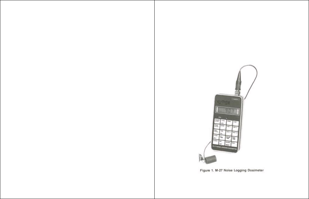
The QUEST M-27 Noise Logging Dosimeter is a microcomputer-based sound analyzing instrument for accumulating, displaying, and sending data to serial or parallel printers or computers. The M-27 functions as a personal noise dosimeter, an area monitor or as a survey events monitor (see Figure 1).
Personal Noise Dosimeter:
Accumulates noise data for OSHA hearing conservation, OSHA
engineering controls, and equal energy noise dosimetry. Accumulates peak and maximum levels. Accumulates 1-minute histograms and 1 dB statistical distributions. Is housed in a secure dustproof case. May be clipped on belt or shirt pocket.
Area Monitor:
Accumulates 40 hours of 1-minute histograms and statistical distributions. May be tripod-mounted.

Events Monitor:
Accumulates the following data for up to 16 separate events: 3 separate integrated sound levels. 3 separate noise doses.
2 time weighted averages and a sound exposure level. Peak level, maximum level, start time, and run time.
The M-27 as an overall unit accumulates data for: 3 separate dosimeters.
3 separate 1 minute time histograms.
2 separate percent time statistical distributions.
2 separate percent dose distributions.
16 separate events.
Sound levels, peaks and maximum levels.
Run time, pause time, and elapsed or real time.
The unit displays:
Sound level, peak level, maximum level.
2 integrated average levels. An equivalent sound level.
3 percent doses.
2 time weighted averages. A sound exposure level. 16 separate events. Run time, pause time, and upper limit time (the time greater than preset level).
Elapsed or real time clock (12 or 24 hour). Calibration level. Code of 24 internal switch settings. The unit prints out:
A heading.
Summary of accumulated data and setup parameters. Up to 16 separate events.
3 separate 1-, 3-, 5-, or 10-minute time histograms. 2 percent time statistical distributions. 2 percent dose statistical distributions.
Raw data for computer storage and manipulations.
Includes editing capability to print out only required data.
The M-27 internal switches select:
Exchange rates of 3, 4, 5, or 6 dB.
Criterion levels of 80, 84, 85, or 90 dB.
2 thresholds of none, 70, 75, 80, 85, or 90 dB. 2 ranges of 35-126 or 50-146 dB.
"A" or "C" frequency weighting.
Fast or slow time constant.
Upper limits of 90, 115, or 140 dB. 12 or 24 hour clocks.
8 different unit numbers. Text, graph, or both printouts. Serial or parallel printers.
Baud rates of 300, 600, 1200, or 2400.
Line feed, carriage return, or both.
The above features, packaged in a compact, rugged, hand-size, easy-to-use instrument, make the QUEST M-27 Noise Logging Dosimeter the "Ultimate" dosimeter.
M-27 SIMPLIFIED OPERATING INSTRUCTIONS
When using the unit gently press key until light click is felt. Hold down until unit responds. Generally this will be immediately, unless the unit is calculating data such as sound level, in which case it may take up to a second.
Control Keys
RUN
PAUSE
RESET
ON
OFF
Starts or continues accumulating data. Display shows run time. Also used to start Events.
Stops accumulation of data. Display counts down from
P-5 to P-l. If key is not released in 5 seconds, unit will
reset, and old data will be lost. Key is also used to reset Clock, Calibrator, Events, and pause the Printout.
If OFF, press to turn on. If ON, hold key down; display counts down from 0-5 to 0-1 and then blank. When
off, data is retained. Key also turns off Print and Events.
NOTE
Data is not lost when the unit is off. Data will be retained for the life of the battery. The only ways to erase data are to hold down PAUSE/RESET for 5 seconds or to remove the battery.
CODE |
Cycles through 7 steps. Press the key for each step. |
HL3 |
Allows the M-27 to display and print data 7 ways. Also |
|
displays a code of internal switch settings. |
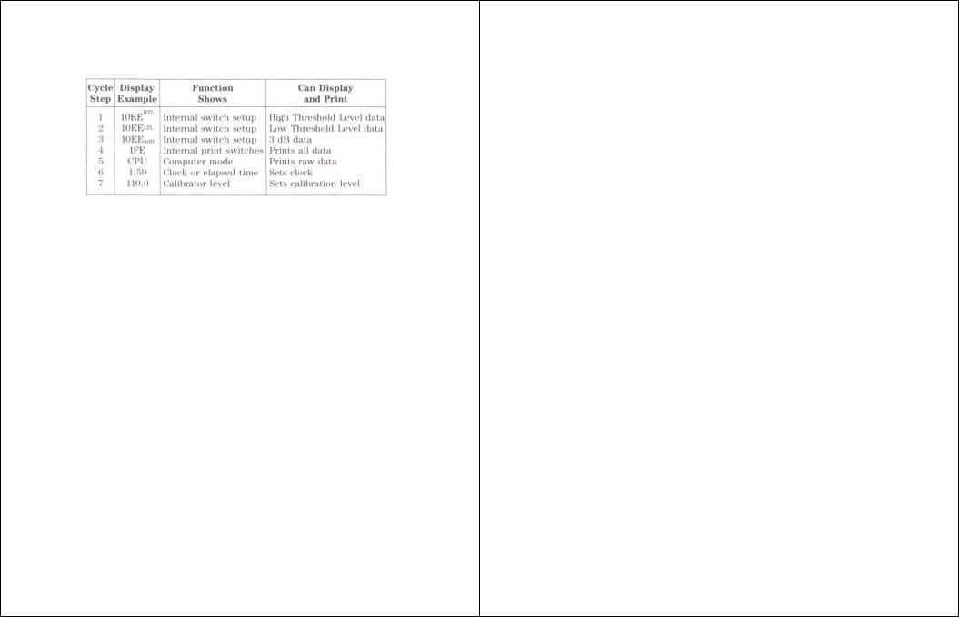
|
In steps 1 to 3 only data for the HTL (High Threshold Level), LTL (Low Threshold |
|
Level), or 3 dB (No Thresh-old) will he displayed or printed. In step 4 data for HTL, |
|
LTL, and 3 dB will be printed. Step 5 dumps raw data to the Computer. Step 6 reads or |
|
resets the Clock. Step 7 reads or stores the Calibrator level. |
Sound Level Meter Keys |
|
SOUND |
Sound Level in decibels. Will repeat each second until |
LEVEL |
another key is pressed. To conserve power, press RUN, |
|
PAUSE or any other key to exit sound level when it is |
|
not needed. |
PEAK |
The highest unweighted Peak Level in decibels during |
LEVEL |
Run Time or an Event. In 30 dB range lowest peak |
|
measurable is 78 dB; in 50 dB range the lowest measurable is 98 dB. |
MAX |
The Maximum Level in decibels after the filter and Slow |
LEVEL |
or Fast time constant circuit. |
Dosimeter Keys |
|
L-AVG |
The average integrated sound level in decibels for the |
LEQ |
HTL (High Threshold Level), LTL (Low Threshold Level), or the equivalent level for 3 |
|
dB. It is the accumulated sound averaged during the Run Time. |
DOSE |
The accumulated Dose in percent for HTL, LTL, or 3 dB. |
TWA |
Time Weighted Average in decibels for HTL and LTL. |
SEL |
It is the accumulated sound averaged over 8 hours. For |
|
3 dB it is the Sound Exposure Level of the accumulated |
|
sound averaged over 1 second. |
Time Keys |
|
RUN |
The total time the unit was running and accumulating |
TIME |
data. If the total time is less than 30 minutes, the co- |
|
lon will blink if the key is held down and the time shown is in minutes and seconds. If the |
|
colon stays on, the time shown is in hours and minutes. |
PAUSE |
The time the unit was on but not accumulating data. |
TIME |
The colon blinks as in Run Time |
. |
|
U.L. |
The time exposure was above the Upper Limit. The |
TIME |
colon blinks as in Run Time. |
Event Keys |
|
|
The event feature accumulates Lavg/Leq, Dose, TWA/SEL for 3 dosimeters, Peak Level, Max |
Level, Run Time, and Start Time for up to 15 different events. Each time a key is pressed in the Event |
|
mode, the display will show the event number and the data. |
|
EVENT |
Enters Events and cycles through the Events with |
|
data. The display shows the event number, a "CE" if it is the Current Event or else a "-E" |
|
for a previous Event. |
|
As an example: 12CE means 12 is the Current Event, 3-E means 3 was a previous Event. |
|
Only previous events with data will be displayed. |
RUN |
Starts accumulating data for the Current Event. |
PAUSE |
Stops accumulating data and cycles to the next Event. |
RESET |
|
ON/OFF |
Exits the Event mode. |
Procedure to Accumulate Event Data |
|
|
To enter the Event mode, press EVENT. To accumulate data, press RUN. To stop, press |
PAUSE/RESET. Press RUN and PAUSE/RESET again to accumulate another event. Press ON/OFF to exit |
|
events. |
|
The following keys can be used to read data in the current event or in any previous event. |
|
CODE |
Cycles through HTL, LTL, and 3 dB. Displays the cur- |
HL3 |
rent time or elapsed time for the current event and |
|
the start time for any previous event. |

L-AVG |
The average or equivalent level for the HTL, LTL, or |
LEQ |
3 dB for the event. |
DOSE |
The percent Dose for the HTL, LTL, or 3 dB for the |
|
event. |
TWA |
The Time Weighted Average for HTL or LTL or the |
SEL |
Sound Exposure Level for the event. |
PEAK |
The Peak Level for the event. |
LEVEL |
|
MAX |
The Maximum Level for the event. |
LEVEL |
|
RUN |
The Run Time of the event. |
TIME |
|
Setting the Clock |
|
|
If the clock is not set, it functions as an elapsed time clock from the time the unit is reset. |
|
The clock can be either a 12or 24-hour clock depending on an internal switch. |
|
When the clock is set to the current time, it will record the actual time for Events and Histograms. |
CODE |
Press until the display includes a colon. The display |
HL3 |
is in hours and minutes. To set clock, press 0 and num- |
|
bers for the current time. The time will move in from the right. The clock is not set until |
|
PAUSE/RESET is pressed. |
PAUSE |
Resets the current time to the number in the display. |
RESET |
The display then shows CLo. |
Recording the Calibration Level |
|
|
The procedure does not calibrate the unit. It stores the CAL level to assure the unit was calibrated. |
CODE |
Press the key until CAL and the current calibration |
HL3 |
level is displayed. To recalibrate the unit, press SOUND |
|
LEVEL with the microphone inserted in a calibrator. |
SOUND |
The display will show SPL (the calibrator level). Wait |
LEVEL |
until the level is steady and press PAUSE/RESET. |
|
If the unit is slightly out of calibration, gently adjust |
|
the CAL screw. If the unit is more than a few decibels out of calibration, it should be |
|
rechecked. |
PAUSE |
Resets the calibration level. Hold key down until the |
RESET |
display shows CAL. |
Using a Printer |
|
|
The printout (Figure 2) can include a heading, a summary of the data, event data, 1 to 3 |
histograms, 1 or 2 percent time statistical distributions, and 1 or 2 percent dose statistical distributions. The |
|
histograms can be of 1, 3, 5, or 10-minute duration. The histograms and statistical distributions can be text, |
|
graphical or both. The printout can be changed and edited before or during printing to print only desired |
|
data. Data is not lost during a printout. |
|
CODE |
To print only HTL, LTL, or 3 dB histograms and statis- |
HL3 |
tical distributions, hold key down until the one desired |
|
is displayed. To print all 3, hold key down until all 3 |
|
are displayed. |
Prints heading, summary, events, and desired histo- |
|
|
grams and distributions. |
HIST 1 |
Prints 1-minute Histograms or 5 minutes per line. If |
|
HTL, LTL, and 3 dB are displayed all 3 will be printed. |
HIST 3 |
Prints 3-minute Histograms or 15 minutes per line. |
HIST 5 |
Prints 5-minute Histograms or 30 minutes per line. |
HIST 10 |
Prints 10-minute Histograms or 1 hour per line. |
|
If HIST 1,3,5, or 10 is pressed during a printout, the next line will print with the new time base for |
a clearer report. |
|
STAT |
Prints a % Time and a % Dose statistical distribution. |
PAUSE |
Pauses the printer to edit printout or adjust printer. |
RESET |
The display shows PSE. To continue printing, press |
|
PAUSE again. Other print keys will alter the printout. |
|
To conserve power do not leave PSE on the display. |
|
ON/OFF will also exit print mode. |
ON |
Stops the printout. If the printer buffer contains data |
OFF |
the printer may run for several seconds after O-5 is |
|
displayed; however, the printout has stopped. |

Dumping Raw Data
|
The data stored in the unit may be transferred to a computer or printer for reprocessing. This data |
is useful only with additional computer programs. Consult Quest for programs. |
|
CODE |
Press key until CPU is displayed. |
HL3 |
|
Prints raw data to computer. |
|
ON |
Stops printout. |
OFF |
|
Changing Printer Parameters |
|
|
Internal switch 3 contains the printer parameters. This switch may be changed without erasing |
stored data. This allows switching printers or computers without destroying data (See Printer Setup, page |
|
32). |
NOTE |
|
|
|
Internal switches 1 and 2 are read only when the unit is RESET. |
SPECIFICATIONS
Standards: |
ANSI S1.4-1983 type 2 |
|
ANSI S1.25-1978 |
|
IEC 651 type 2 |
UL Intrinsic Safety: |
|
|
Class I Group C, D |
|
Class II Group E, F |
|
Class III |
Detector: |
True RMS; 63 dB pulse range |
Display: |
Liquid crystal display |
|
Range: .01 to 2999 |
|
Annunciators: HTL, LTL, 3 dB, LOBAT, RUN, and PAUSE |
Printout: |
RS-232 serial at 300, 600, 1200, or 2400 baud |
|
or Centronics parallel Connector: 20 pin shrouded header |
Microphone: |
8 mm PZT ceramic, 36-inch cable, field replaceable |
Battery: |
Single 9-volt alkaline, 80-hour battery life |
Battery Indicator: 8-hour battery life, 1 week data retention
Calibrator: |
External calibrator |
Temperature: |
-15° to 50°C operating; -40° to 60°C storage (battery removed). |
Humidity: |
0 to 95% non-condensing |
Magnetic Field Effects: |
|
|
Negligible below 50 Oersteds at 50 to 60 Hz |
Size: |
5 ½ x 2 ¾ x 1 3/8 inches |
|
(140 x 70 x 40 mm) |
Weight: |
14 ounces (400 grams) |
Construction: |
Cast aluminum housing with tamper-, water-, and dust-resistant security cover. |
GENERAL DESCRIPTION
The microprocessor based M-27 Noise Logging Dosimeter can be used as a personal noise dosimeter, an area monitor, and as a noise survey instrument. It can be used to check compliance with the requirement of the Occupational Safety and Health Administration (OSHA), or as a community or Department of Defense noise logging dosimeter.
The M-27 simultaneously monitors multiple noise functions for 3 separate dosimeters as well as sound, peak, and maximum levels, and run, pause, upper limit, and real or elapsed times. It also stores, displays, and prints out data for 16 different events.
The readings can be taken at any time without destroying or resetting the data. Even turning the unit off will not destroy the internal memory.
A waterand dust-resistant cover protects the unit from the elements and against tampering.
The unit is small enough to be placed in a shirt pocket or on a belt with the microphone clipped to the shirt collar or on the shoulder. The microphone can be attached to a bracket for use as a sound level meter. Or the unit can be mounted on a tripod for area surveys.
The M-27 is powered by a single 9-volt transistor battery with an 80-hour battery life. A low battery indication is displayed 8 hours before the end of life of an alkaline battery.
PRINCIPLES OF OPERATION General
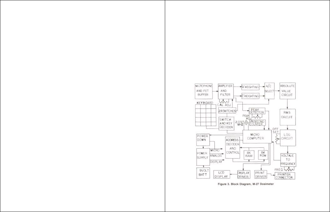
The M-27 Noise Logging Dosimeter uses an 8 mm omnidirectional ceramic microphone buffered by a high impedance FET input stage.
The electronics utilizes low power circuitry for long battery life, maximum stability, and high reliability over a wide range of environmental conditions. A block diagram of the M-27 is shown in Figure 3.
Weighting Characteristics
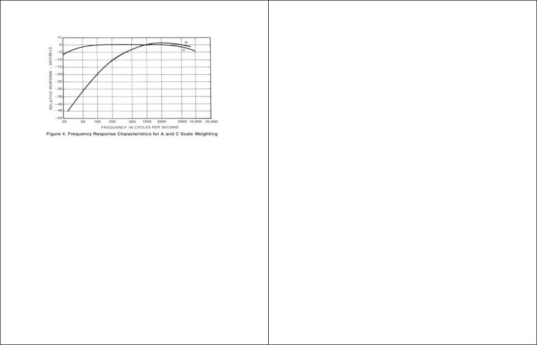
The M-27 has both "A" and "C" weighting characteristics as shown in Figure 4. For OSHA and most noise measurement requirements, the "A" weighting should be used. The "A" weighting has a response similar to the human ear. The "C" weighting is used for measuring noise reduction in hearing protectors and for other scientific purposes.
It also has a 1 second Slow and a.125 second Fast time constant circuit. Present OSHA requirements specify Slow.
Microcomputer Modes
The M-27 is controlled by a MC146805 CMOS Microcomputer. The system has 8192 bytes of RAM, 6144 bytes of ROM, a 33-segment LCD, 24 programming switches, serial and parallel printer outputs, a V/F converter for continuous dose integration, and power down circuits to retain data when off.
The M-27 operates in one of the following 6 modes.
Reset Mode
The M-27 enters the reset mode when the unit is reset or a battery is installed. In this mode power is applied to the unit, all previous data is cleared, the internal switches are read, the counter is cleared, the pause register is set, three dashes are placed on the display, and the unit enters the wait mode.
Wait Mode
The microcomputer waits for an interrupt to occur. During the wait mode it continues to gather data from the voltage to frequency converter. Otherwise the microcomputer is in a low power state. When the 1/16 second interrupt occurs the unit enters the pause or run mode.
Pause Mode
In this mode, the Slow or Fast time constant sound level is computed and pause time and the elapsed or real time clocks are incremented. At every interrupt the keyboard is checked to see if any key is pressed - unless it is doing a previous calculation such as sound level when it may delay for up to 1 second. If a key is pressed the computer enters the compute mode. Otherwise it returns to the wait mode.
Run Mode
The same as the pause mode except the data necessary to compute Lavg, Leq, Dose, TWA, SEL, Peak, Max, Run Time, Upper Limit, as well as Event data is accumulated.
Compute Mode
If a key has been pressed in the pause or run modes, the M-27 will compute and display the desired function. If the key is held down it will recompute it one second later using the data accumulated during that second. If the data will not compute (as an example, Lavg will not compute if the sound level never exceeds the threshold level) the display will either show three dashes or display LO.
If the print key has been pressed, the processor will compute one line of print and send the data to the printer output. The printer output may be terminated by pressing the ON/OFF key until 0-5 is displayed. Pressing PAUSE will cause the printer to stop. Press PAUSE to continue. When PSE is displayed, the unit draws extra current and should not be left in this state. ON/OFF will exit PSE. The computer continues to accumulate data during a printout. For best results the computer should be placed in the pause mode during a printout.
When computing is completed, the processor returns to the wait mode.
Stop Mode
If the ON/OFF key has been depressed for 5 seconds, the M-27 enters the stop mode. In the stop mode the processor stops accumulating, but does not erase, data. Power is removed from the analog circuitry and the display circuitry. The oscillator is stopped. Only a few microamps of current are drawn from the battery to maintain the microcomputer's memory and to power the ON/OFF key.
When the ON/OFF key is then pressed the computer returns to where it was before it was turned off except it will be in the pause mode.
 Loading...