


MAGNA 121A
P. 1
- AUDIOL AB Magna 121A
MAGNA 121A
Self-powered subwoofer – 1 x 21”
USER MANUAL

P. 2
AUDIOLAB Magna 121A -
MAGNA 121A
Self-powered subwoofer – 1 x 21”
Magna 121A is a 21" self-powered subwoofer with
a 4" voice coil that delivers 1000W continuous.
Thanks to its D-type amplication, the equipment
achieves great power with a very good sound
quality and a very low weight design. Magna 121A
has a frequency response ranging from 40Hz
to 120Hz and has a control panel that allows
inverting the phase and choosing the crossover
frequency for the tops between 60Hz, 80Hz and
100Hz. Ideal for medium-scale mobile applications
thanks to its rugged construction, its amplication
also features a highly ecient protection circuit.
Specications
Components
• LF: 1 x 21" Woofer with 4" voice coil
Features
• Self-powered 21" Subwoofer
• Crossover frequency: DSP Processing
60Hz/80Hz/100Hz
• Frequency response (-6dB): 40Hz-120Hz
• Max SPL: 130 dB @ 1M
• Cooling: Temperature-controlled fan
• Enclosure design: Plywood cabinet, resistant
black paint, metal grille with foam & rubber feet
• Mounting: One metal standard pole-mount
Amplier & Control
• Power output: 1000W RMS
• Amplier type: Class D
• Protections: Thermal / Convection-Fan / Over-
load / Digital Compressor / Limit
• Controls: Volume Control / Phase switch /
Crossover frequency switch / Ground Lift
Connectors
• Inputs:
• 1 XLR-3/Plug combo
• 1 XLR-3
• Output: 2 XLR-3
• Link: 2 XLR-3
• Power supply: 2 PowerCon (Input/Link)
Physical
• Dimensions: 745x625x578 mm. /
29.3x24.6x22.8 in
• Weight 48 Kg. / 105.8 Lbs.
1. OVERVIEW
English version
P. 3
- AUDIOL AB Magna 121A
English version
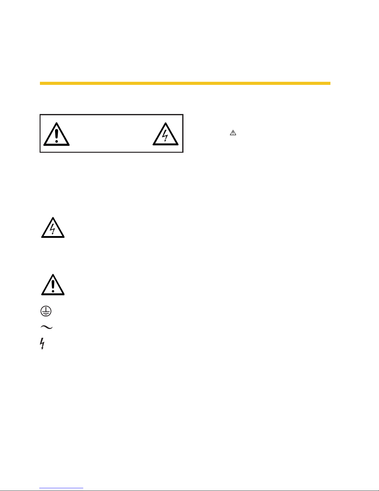
2. SAFETY RELATED SYMBOLS
To reduce the risk of electric shock please do
not remove the cover or the back panel of this
equipment.
There are no parts needed by user inside the
equipment. For service, please contact qualied service centers.
This symbol, wherever used, alerts you
to the presence of un-insulated and
dangerous voltages within the product
enclosure. These are voltages that may be suf-
ecient to constitute the risk of electric shock or
death.
This symbol, wherever used, alerts you
to important operating and maintenance instructions.
Protective Ground Terminal.
AC mains (Alternating Current)
Hazardous Live Terminal
ON: Denotes the product is turned on.
OFF: Denotes the product is turned o.
Caution
Describes precautions that should be observed to
prevent damage to the product.
1. Read this Manual carefully before operation.
2. Keep this Manual.
3. Be aware of all wamings reported with this
symbol.
4. Keep this Equipment away from water and
moisture.
5. Clean it only whith dry doth. Do not use solvent or other chemicals.
6. Do not damp or cover any cooling opening.
Install the equipment only in accordance
with the Manufacturer's instructions.
7. Power Cords are designed for your safety.
Do not remove Ground connections! If the
plug does not t your AC outlet, seek advice
from a qualied electrician. Protect the pow-
er cord and plug from any physical stress
to avoid risk of electric shock. Do not place
heavy objects on the power. This could cause
electric shock or re.
8. Unplug this equipment when unused for
long periods of time or during a storm.
9. Refer all service to qualied service person-
nel only. Do not perform any servicing other
than those instructions contained whithin
the User's Manual.
10. To prevent re and damage to the product,
use only the recommended fuse type as
indicated in this manual. Do not short-circuit
the fuse holder.
Warning
To reduce the risk of electric shock and re, do
not expose this equipment to moisture or rain.
Dispose of this product should not be placed
in municipal waste and should be separate
collection.
Before replacing the fuse, make sure that the
product is OFF and disconnected from AC outlet.
RISK OF ELECTRIC SHOCK
DO NOT OPEN.
CAUTION!

P. 4
AUDIOLAB Magna 121A -
English version
11. Move this Equipment only with
a cart, stand, tripod, or bracket, specied by the manufacturer, or sold with the Equipment. When a cart is used, use
caution when mobing the cart/
equipment combination to avoid possible
injury from tip-over.
12. Permanent hearing loss may be caused by
exposure to extremely high noise levels. The
US Government's Occupational Safety and
Health Administration (OSHA) has specied
the permissible exposure to noise level.
These are shown in the following chart:
According to OSHA, an exposure to high SPL in
excess of these limits may result in the loss of heat.
To avoid the potential damage of heat, it is recommended that Personnel exposed to equipment
capable of generating high SPL use hearing protection while such equipment is under operation.
The apparatus shall be connected to a mains socket outlet with a protective earthing connection.
The mains plug or an appliance coupler is used as
the disconnect device, the disconnect device shall
remain readily operable.
Hours x day SPL Example
8 90 Small gig
6 92 Train
4 95 Subway train
3 97 High level desktop monitors
2 100 Classic music concert
1.5 102
1 105
0.5 110
0.25 or less 115 Rock Concert
P. 5
- AUDIOL AB Magna 121A
English version
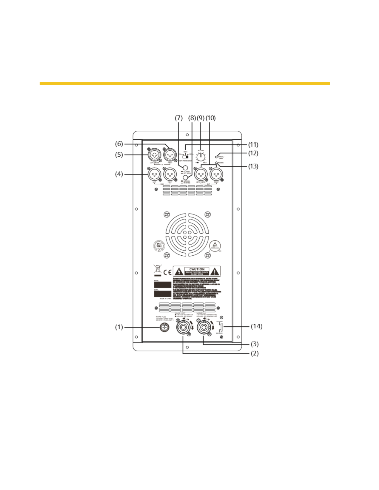
3. BACK PANEL DESCRIPTION
9. Volume main power control
10. Left-Right Line Output XLR connector
11. Crossover 60Hz/80Hz/100Hz
12. Limit and signal presence red LED
13. Power and activity indicator green LED
14. Voltage selector
1. Mains Fuse
2. Mains Input
3. Mains Link
4. Left-Right Link XLR connector
5. Left line mono input Combo connector
6. Right line input XLR connector
7. High pass lter or bypass selector
8. Normal/Reverse phase switch (Polarity)

P. 6
AUDIOLAB Magna 121A -
4. CONNECTION PLATE
Make your initial connections with all the equipment powered o, and ensure that all the main
volume controls are turned completely down.
Two Active Subwoofers & Two Active Satellite
Speakers
1. Connect one side of the signal cable at your
mixer into the output Left/Right and the other
side of the cable into the Line Input of your
active subwoofers.
2. Connect one side of another signal cable at
your active subwoofers into Link Left/Right or
Out Left/Right, and the other side of the cable
into the Line Input Left/Right of your active
satellite speakers. *If you connect into Out
Left/Right and press Bypass switch, the 80Hz
HPF will be activated.
3. Connect the power cord to main.
4. Turn ON your mixer rst, the the active
speaker cabinets.
5. Turn up the volume control of the active
speaker cabinets.
6. Use PFL function to get the proper input level
for the mixer, and adjust the Main Mix Level
control to reach the desired output level.
7. After use, turn o your active speaker cabi-
nets, then the mixer.
Line
Input
Line
Input
Mixer
Line in
Left/Mono
Line in
Right/Mono
Main Out Left
Main Out Right
Pole Pole
English version
 Loading...