

Page 1

User's Manual
AudioCodes CPE & Access Gateway Products
MP-20x Telephone Adapter
Version 4.5.0
Page 2

Page 3

Version 4.5.0 3 MP-20x Telephone Adapter
User's Manual Contents
Table of Contents
1 Introduction ....................................................................................................... 11
2 Cabling the MP-20x Telephone Adapter .......................................................... 13
3 Setting up a Network Connection .................................................................... 15
3.1 Defining Your PC's Network Connection .............................................................. 15
3.1.1 Configuring your PC Running Windows 10 .............................................................16
3.1.2 Configuring your PC Running Linux ........................................................................18
3.2 Configuring the MP-20x's Network Connection ..................................................... 18
3.2.1 Logging in to MP-20x Web Interface .......................................................................18
3.2.2 Configuring 'Quick Setup' Screen Parameters ........................................................19
3.2.2.1 Configuring Your Internet Connection ......................................................19
3.2.3 Configuring 3G/LTE USB Modem ...........................................................................24
4 Device Quick Setup ........................................................................................... 27
4.1 Preparing Initial Configuration .............................................................................. 27
4.2 Configuring SIP Signaling Protocol ....................................................................... 28
5 Getting Started with the Web Interface ........................................................... 31
5.1 Logging into the Web Interface ............................................................................. 31
5.2 Menu Bar Description ........................................................................................... 32
5.3 Managing Tables .................................................................................................. 35
5.4 Configuring Users ................................................................................................. 36
5.4.1 Web User Permissions ............................................................................................39
5.4.1.1 Print Commands .......................................................................................39
5.5 Set Commands ..................................................................................................... 48
5.6 Associated Elements ............................................................................................ 49
5.6.1 Configuring Scheduler Rules ...................................................................................49
5.6.2 Configuring Network Objects ...................................................................................51
5.6.3 Configuring Protocols ..............................................................................................53
5.7 Logging out the Web Interface .............................................................................. 54
6 Viewing a Graphical Display of the Device's Network ................................... 55
7 Configuring Computers for Connecting to Device's Network ....................... 57
7.1 Wired Computers ................................................................................................. 57
7.1.1 Configuring Computers Running on Windows 7 .....................................................57
7.1.2 Configuring Computers Running on Linux...............................................................58
8 Setting up your Device ..................................................................................... 59
8.1 Setting up an Internet Connection using the Web Interface .................................. 59
8.1.1 WAN Ethernet ..........................................................................................................60
8.1.1.1 Manual IP Address Ethernet Connection .................................................60
8.1.1.2 Automatic IP Address Ethernet Connection .............................................61
8.1.1.3 PPPoE ......................................................................................................61
8.1.1.4 PPTP ........................................................................................................62
8.2 Using the Automatic Dialer for Internet Connection .............................................. 63
8.2.1 Recommended Configuration ..................................................................................63
8.2.2 Setting up and Starting the Automatic Dialer...........................................................64
8.2.3 Quitting Automatic Dialer for Manual Configuration ................................................64
Page 4

User's Manual 4 Document #: LTRT-50619
MP-20x Telephone Adapter
9 Configuring VoIP Parameters .......................................................................... 65
9.1 Configuring the SIP Signaling Protocol ................................................................. 66
9.1.1 Configuring Proxy Redundancy ...............................................................................71
9.1.2 Support for DNS Failover Mechanism .....................................................................73
9.2 Support for Common Name/SubjectAltName Verification for SIP ......................... 74
9.3 Support for Advanced Alerting with Ring Splash ................................................... 74
9.4 Configuring Dialing Parameters ............................................................................ 74
9.4.1 Syntax for Digit Maps and Dial Plans ......................................................................79
9.5 Configuring Media Streaming ................................................................ ............... 81
9.5.1 SRTP .......................................................................................................................83
9.5.1.1 Support for Dynamic SRTP Policy ...........................................................83
9.5.1.2 Changing Default Cipher Suites for SIP Over TLS ..................................84
9.5.1.3 Support for RFC 3329 & MediaSec Extensions .......................................84
9.5.1.4 Configuring Codecs ..................................................................................84
9.5.2 Supported Codecs ...................................................................................................84
9.5.2.1 Packetization Time ...................................................................................84
9.6 Configuring Voice and Fax ................................................................................... 85
9.7 Configuring Supplementary Services .................................................................... 90
9.7.1 Network-based Conferencing (RFC 4240) ..............................................................93
9.8 Voice Menu Guidance .......................................................................................... 94
9.8.1 Configuring Voice Menu ..........................................................................................94
9.8.1.1 Voice Menu Configuration Parameters ....................................................94
9.9 Configuring Micro PBX Line Settings .................................................................... 96
9.10 Configuring Line Extensions ................................................................................. 99
9.11 Configuring Speed Dialing .................................................................................. 101
9.12 Enabling Polarity Reversal .................................................................................. 103
10 Making VoIP Calls with your Analog Telephones ........................................ 105
10.1 Making a Call ...................................................................................................... 105
10.2 Answering a Waiting Call .................................................................................... 105
10.3 Putting a Call on Hold ......................................................................................... 106
10.4 Transferring a Call .............................................................................................. 106
10.5 Forwarding Calls to another Phone .................................................................... 107
10.6 Establishing a 3-Way Conference Call................................................................ 108
11 Quality of Service ............................................................................................ 109
11.1 QoS Wizard ........................................................................................................ 110
11.2 Configuring Traffic Shaping ................................................................................ 111
11.2.1 Configuring Traffic Shaping ...................................................................................112
11.2.2 Configuring Shaping Classes ................................................................................114
11.2.2.1 Class Rules ............................................................................................115
11.3 Configuring Traffic Priority .................................................................................. 117
11.4 Configuring DSCP Mapping ................................................................................ 121
11.5 Configuring 802.1p Mapping ............................................................................... 123
11.6 Configuring Class Statistics ................................................................................ 124
11.7 Configuring Basic VoIP QoS Example ................................................................ 125
12 Network Connections ..................................................................................... 127
12.1 Configuring a WAN Connection .......................................................................... 127
12.1.1 WAN Ethernet Connections ...................................................................................129
Page 5

Version 4.5.0 5 MP-20x Telephone Adapter
User's Manual Contents
12.1.1.1 External DSL Modem using PPPoE .......................................................129
12.1.1.2 External Cable Modem/Fiber Transceiver without Authentication .........131
12.1.1.3 DHCP .....................................................................................................133
12.1.1.4 Manual IP Address .................................................................................134
12.2 LAN Connection ................................................................................................. 137
12.2.1 LAN Ethernet .........................................................................................................137
12.2.1.1 General Tab ...........................................................................................138
12.2.1.2 Settings Tab ...........................................................................................138
12.2.1.3 Routing Tab ............................................................................................139
12.2.1.4 Advanced Tab ........................................................................................139
12.3 WAN Connection ................................................................................................ 141
12.3.1 General Tab ...........................................................................................................141
12.3.2 Settings Tab ...........................................................................................................142
12.3.2.1 Internet Protocol Settings .......................................................................143
12.3.3 Routing Tab ...........................................................................................................146
12.3.4 PPP Tab ................................................................................................................148
12.3.5 PPTP Tab ..............................................................................................................150
12.3.6 Advanced Tab ........................................................................................................151
12.4 VLAN Settings .................................................................................................... 152
12.4.1 Settings Tab ...........................................................................................................155
12.4.1.1 IP Address Distribution ...........................................................................156
12.4.2 Routing Tab ...........................................................................................................158
12.4.3 Advanced Tab ........................................................................................................159
12.5 LAN-WAN Bridge Settings .................................................................................. 160
12.5.1 Editing LAN-WAN Bridging ....................................................................................162
13 IPv6 ................................................................................................................... 165
13.1 IPv6 Features ..................................................................................................... 165
13.2 Configuring IPv6 ................................................................................................. 166
13.2.1 Configuring IPv6 using CLI ....................................................................................166
13.2.2 Configuring IPv6 using Web ..................................................................................166
13.3 Configuring Connections on IPv6 ....................................................................... 167
13.3.1 Configuring SLACC ...............................................................................................167
13.3.1.1 Configuring Stateless IP Address using CLI ..........................................167
13.3.1.2 Configuring Stateless IP Address using Web ........................................167
13.3.2 Obtaining IPv6 DNS Server by DHCPv6 with 'O' Flag ..........................................168
13.3.3 Obtaining IPv6 NTP Server by DHCPv6 with 'O' Flag ...........................................169
13.4 Supported IPv6 Features .................................................................................... 172
13.4.1 ICMPv6 ..................................................................................................................172
13.4.1.1 Ping ICMPv6 using CLI ..........................................................................172
13.4.1.2 Ping Using Web Interface.......................................................................172
13.4.2 NTP Server IPv6 ....................................................................................................172
13.4.3 Management over IPv6..........................................................................................172
13.4.4 Allow Incoming WAN ICMP Echo Request over IPv6 ...........................................173
13.4.5 Provisioning over IPv6 (Configuration / Firmware) ................................................173
13.4.6 VoIP .......................................................................................................................173
13.4.6.1 Configuring SIP Proxy for IPv6 ..............................................................173
13.4.6.2 Configuring Speed Dial for IPv6 .............................................................173
13.4.6.3 Configuring Outbound Proxy as IPv6 .....................................................174
13.4.6.4 Configuring Redundancy Proxy as IPv6 ................................................175
14 Add-on Servers and Disk Management ......................................................... 177
14.1 External File Server ............................................................................................ 177
14.1.1 Automatic File Sharing ...........................................................................................178
Page 6

User's Manual 6 Document #: LTRT-50619
MP-20x Telephone Adapter
14.2 Print Server ........................................................................................................ 180
14.2.1 Connecting and Setting up a Printer on Windows .................................................181
14.2.2 Print Protocols .......................................................................................................182
14.2.2.1 Internet Printing Protocol ........................................................................183
14.2.2.2 Microsoft Shared Printing (Samba) ........................................................191
14.2.2.3 Line Printer Daemon (LPD) ....................................................................194
14.2.3 Storing and Using Printer Drivers ..........................................................................202
15 Remote Device Management .......................................................................... 203
15.1 Overview ............................................................................................................ 203
15.1.1 Remote Configuration ............................................................................................203
15.1.2 Remote Management ............................................................................................205
15.1.2.1 Firmware Upgrade ..................................................................................205
15.1.2.2 Status and Performance Monitoring .......................................................206
15.1.2.3 Alarms, Notifications and Logging ..........................................................207
15.2 Enabling Remote Management .......................................................................... 208
15.2.1 Enabling Local or Remote Management using the SSH Protocol .........................211
15.3 Securing Remote Management with Certificates ................................................ 212
15.4 Remote Configuration and Management Interfaces ............................................ 216
15.4.1 Embedded Web Server .........................................................................................216
15.4.2 TR-069 and TR-104 CPE WAN Management Protocol ........................................217
15.4.2.1 Configuring the Device via TR-069 and TR-104 ....................................218
15.4.2.2 Monitoring the Device Status via TR-069 and TR-104 ..........................226
15.4.2.3 Security Concerns and Measures ..........................................................230
15.4.3 SNMP.....................................................................................................................230
15.4.3.1 Enabling SNMP in the Web Interface .....................................................231
15.4.3.2 Configuring the Device via SNMP ..........................................................232
15.4.3.3 Status Monitoring of System and Network Interfaces via SNMP ...........232
15.4.3.4 Security Concerns and Measures ..........................................................233
15.4.4 Syslog ....................................................................................................................234
15.4.5 Automatic File Download .......................................................................................234
15.4.5.1 Firmware File Download .........................................................................234
15.4.5.2 Configuration File Download ..................................................................234
15.4.5.3 Security Concerns and Measures ..........................................................235
15.4.6 Telnet CLI ..............................................................................................................235
15.4.7 Redirect Server ......................................................................................................235
15.4.8 BroadSoft BroadWorks DMS Provisioning ............................................................237
15.4.9 Provisioning using DHCP Options 66/67 and TFTP ..............................................237
15.4.9.1 Default Behavior .....................................................................................237
15.4.9.2 Disabling DHCP Options 66 and 67 .......................................................238
15.4.10 Setting Provisioning Time of Day (TOD) ...............................................................238
15.4.10.1 Random TOD .........................................................................................238
15.4.10.2 Fixed TOD ..............................................................................................239
15.4.10.3 No TOD Configured – Default Behavior .................................................239
15.4.10.4 Changing Default Cipher Suits for Provisioning .....................................239
16 Security ............................................................................................................ 241
16.1 General Security Level Settings.......................................................................... 242
16.2 Configuring Access Control ................................................................................ 244
16.3 Configuring Port Forwarding ............................................................................... 246
16.4 Configuring a DMZ Host ..................................................................................... 249
16.5 Configuring Port Triggering ................................................................................. 250
16.6 Configuring Website Restrictions ........................................................................ 253
16.7 Configuring NAT ................................................................................................. 256
16.8 Viewing Current Connections ................................................................ ............. 259
Page 7

Version 4.5.0 7 MP-20x Telephone Adapter
User's Manual Contents
16.9 Configuring Advanced Filtering ........................................................................... 260
16.10 Viewing the Security Log .................................................................................... 264
17 Advanced Networking Features ..................................................................... 267
17.1 IP Address Distribution ....................................................................................... 267
17.1.1 Configuring the DHCP Server ...............................................................................269
17.1.2 Configuring DHCP Relay .......................................................................................270
17.1.3 Viewing DHCP Clients ...........................................................................................271
17.1.4 Configuring Static DHCP Clients ...........................................................................272
17.2 Configuring a DNS Server .................................................................................. 273
17.3 Configuring Dynamic DNS ................................................................ .................. 275
17.4 Configuring Routing Rules .................................................................................. 278
17.4.1 Managing Routing Table Rules .............................................................................279
17.4.2 Configuring Routing Protocols ...............................................................................280
17.5 Enabling PPPoE Relay ....................................................................................... 281
17.6 Selecting Regional Settings for Analog Lines ..................................................... 282
17.7 Installation Wizard .............................................................................................. 283
18 Home Media ..................................................................................................... 285
18.1 Universal Plug and Play ..................................................................................... 285
18.1.1 Enabling Universal Plug and Play on the Device ..................................................285
18.1.2 Adding UPnP-enabled PC to Home Network ........................................................286
18.1.3 Monitoring Connection Between the Device and Internet .....................................287
18.1.4 Making Local Services available to PCs on Internet .............................................288
19 Configuring the Device for PacketSmart ....................................................... 291
19.1 Configuring PacketSmart through the Web Interface .......................................... 291
19.2 Configuring PacketSmart through the CLI .......................................................... 294
19.3 Upgrading PacketSmart on the Fly ..................................................................... 295
19.4 Accessing the PacketSmart Web Portal ............................................................. 296
20 Media Sharing ................................ ................................ ................................ .. 299
20.1 Share Music, Pictures and Video on My Local Network ...................................... 299
20.2 Automatically Share Media in All Folders ............................................................ 300
21 Maintenance .................................................................................................... 303
21.1 Enabling the Feature Key ................................................................................... 303
21.2 Viewing the Device Software Version ................................................................. 305
21.3 Configuring Date and Time ................................................................................. 306
21.4 Configuration File ............................................................................................... 309
21.4.1 Uploading Configuration File from PC on the Network ..........................................311
21.4.2 Uploading Configuration File from a Remote Server .............................................313
21.4.3 Remote Configuration Provisioning Based on MD5 Checksum Comparison .......316
21.4.4 Encrypting the Configuration File using CLI ..........................................................317
21.4.5 Automatic Upload using SIP NOTIFY Message ....................................................318
21.5 Firmware Upgrade .............................................................................................. 319
21.5.1 Upgrading the Device from a Computer on the Network .......................................320
21.5.2 Upgrading the Device from the Internet .................................................................323
21.6 Configuring System Settings .............................................................................. 325
21.7 Rebooting the Device ......................................................................................... 328
21.8 Restoring Factory Settings ................................................................................. 329
Page 8

User's Manual 8 Document #: LTRT-50619
MP-20x Telephone Adapter
22 Diagnostics and Performance Monitoring .................................................... 331
22.1 Running Diagnostics ........................................................................................... 331
22.1.1 Running the Ping Test ...........................................................................................332
22.1.2 Running the ARP Test ...........................................................................................332
22.1.3 Running a Traceroute ............................................................................................333
22.2 Running Debug .................................................................................................. 334
22.2.1 Running Packet Recording ....................................................................................335
22.2.2 Running SIP Debug Log ........................................................................................336
22.2.3 Running TCPDump ................................................................................................337
22.2.3.1 Updating Wireshark ................................................................................337
22.2.3.2 Running TCPDump with Destination Port 7555 .....................................337
22.2.3.3 Defining a Different Destination Port (other than Port 7555) .................338
22.2.4 Running Generic Commands ................................................................................339
22.2.5 Commands Output and Report ..............................................................................340
22.3 System Monitoring .............................................................................................. 343
22.3.1 Viewing Network Connections Status ....................................................................343
22.3.2 Viewing the System Log ........................................................................................344
22.3.3 Viewing CPU Statistics ..........................................................................................345
22.3.4 Viewing VoIP Traffic Statistics ...............................................................................346
22.3.5 Viewing Internet Connection Utilization .................................................................347
22.3.6 Using Debugging Tools .........................................................................................348
22.4 Call Detail Records ............................................................................................. 349
22.4.1 CDR Field Descriptions .........................................................................................349
22.4.2 Release Reasons in CDR ......................................................................................351
22.4.3 Configuring CDR Reporting ...................................................................................351
22.4.4 CDR Log Local Storage .........................................................................................352
A Technical Specifications ................................................................................ 353
A.1 Device Gateway Specifications .......................................................................... 353
Page 9
User's Manual Notices
Version 4.5.0 9 MP-20x Telephone Adapter
Notice
Information contained in this document is believed to be accurate and reliable at the time of
printing. However, due to ongoing product improvements and revisions, AudioCodes cannot
guarantee accuracy of printed material after the Date Published nor can it accept responsibility
for errors or omissions. Updates to this document can be downloaded from
https://www.audiocodes.com/library/technical-documents.
This document is subject to change without notice.
Date Published: March-18-2021
WEEE EU Directive
Pursuant to the WEEE EU Directive, electronic and electrical waste must not be disposed of
with unsorted waste. Please contact your local recycling authority for disposal of this product.
Customer Support
Customer technical support and services are provided by AudioCodes or by an authorized
AudioCodes Service Partner. For more information on how to buy technical support for
AudioCodes products and for contact information, please visit our website at
https://www.audiocodes.com/services-support/maintenance-and-support.
Stay in the Loop with AudioCodes
Abbreviations and Terminology
Each abbreviation, unless widely used, is spelled out in full when first used.
General Notes, Warnings, and Safety Information
Note: OPEN SOURCE SOFTWARE. Portions of the software may be open source
software and may be governed by and distributed under open source licenses, such
as the terms of the GNU General Public License (GPL), the terms of the Lesser
General Public License (LGPL), BSD and LDAP, which terms are located at
https://www.audiocodes.com/services-support/open-source/ and all are incorporated
herein by reference. If any open source software is provided in object code, and its
accompanying license requires that it be provided in source code as well, Buyer may
receive such source code by contacting AudioCodes, by following the instructions
available on AudioCodes website.
Page 10

User's Manual 10 Document #: LTRT-50619
MP-20x Telephone Adapter
Document Revision Record
LTRT
Description
50610
Initial document release.
50611
Provisioning using DHCP Options 66 & 67 and TFTP Server sections were added.
50612
MP-204B features were added.
50613
The Remote Configuration and Management Interfaces section was updated.
50614
The PacketSmart Configuration section was updated.
50615
Introduction section was updated. Network Parameters section was removed. Support
for CN/SANS and SRTP sections were added. T.38 Version and 3-Way Conference
Mode parameters were added. The Max Rate parameter was updated. Screenshots
were updated.
50616
New note in Introduction; Replaced Windows XP instructions with Windows 10
instructions, Restoring factory settings, Support for DNS Failover Mechanism; Support
for Advanced Alerting with Ring Splash; Support for Dynamic SRTP Policy;
Network-based Conferencing (RFC 4240); Configuring Date and Time;
Automatic Upload using SIP NOTIFY Message; Restoring Factory Settings; Using
Debugging Tools
Deleted L2TP connection; External Cable Modem/Fiber Transceiver with L2TP; using
the Internet Dialer for Automatic Connections.
50617
Added Call Detail Records.
50618
Added Changing Default Cipher Suites for SIP over TLS; Setting Provisioning Time of
Day (and sub-sections)
50619
Added IPv6 section.
Documentation Feedback
AudioCodes continually strives to produce high quality documentation. If you have any
comments (suggestions or errors) regarding this document, please fill out the
Documentation Feedback form on our Web site at
http://online.audiocodes.com/documentation-feedback.
Page 11
User's Manual 1. Introduction
Version 4.5.0 11 MP-20x Telephone Adapter
1 Introduction
AudioCodes MP-20x series of analog Telephone Adapters are cost-effective, feature-rich
gateways, allowing the connection of ordinary POTS analog telephones or fax machines to
a Voice-over-Broadband (VoBB) service provider.
The MP-20x series is designed for the rapidly growing residential and Small Office/Home
Office (SOHO) voice-over-IP (VoIP) market. The MP-20x series typically connects to an
existing Broadband Internet device (Cable and ADSL modem, - depending on model), and
establishes a communications path with the service provider network through its IP uplink
connection. Supporting a rich set of subscriber calling features such as caller ID, call
forwarding, and call waiting, the MP-20x series maintains a uniform user experience when
migrating to VoIP services. In addition, the MP-20x series serves as a router with capabilities
such as DHCP, NAT, Firewall, PPPoE and PPTP, supporting connectivity of home PC
networks.
The MP-20x VoIP Gateway is an all-in-one unit featuring (depending on model) a VoIP
adapter, FXS lines, Ethernet LAN interfaces (with an internal Layer-2 switch), and Ethernet
WAN interface.
Utilizing AudioCodes' VoIPerfect™ core architecture, and gaining from its accumulated
experience in providing IP telephony solutions, the MP-20x series combines superior voice
quality and cutting-edge features for end users, such as T.38 Fax Relay and G.168-2004
compliant Echo Cancellation. Low bit rate vocoders (voice coders) can be used
simultaneously on all the telephony ports to save valuable bandwidth.
The MP-20x is available in the following models:
Table 1-1: MP-20x Models
Model
FXS
WAN
LAN
USB 2.0
Ethernet Relay
MP-202B/2S/SIP
2 1 1 - -
MP-204B/4S/SIP
4 1 1 1 -
MP-202R/2S/SIP/CER/R
2 1 1
1
✓
MP-204R/4S/SIP/CER/R
4 1 1
1
✓
Note: MP-202R/MP-204R (128M RAM + Ethernet Relay Control) is now supported. The
RAM memory has been increased and Ethernet Relay controlled by software now
ensures minimal downtime if power is lost.
Page 12
User's Manual 12 Document #: LTRT-50619
MP-20x Telephone Adapter
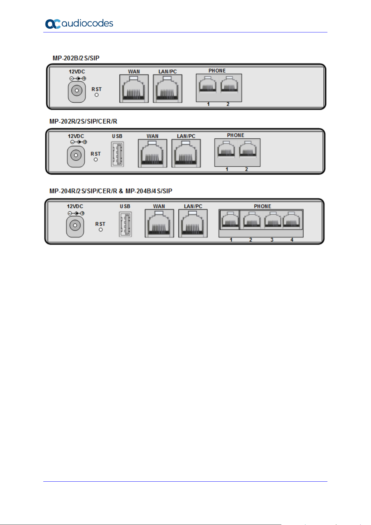
Figure 1-1: Rear Panel MP-20xB Models
Page 13
User's Manual 2. Cabling the MP-20x Telephone Adapter
Version 4.5.0 13 MP-20x Telephone Adapter
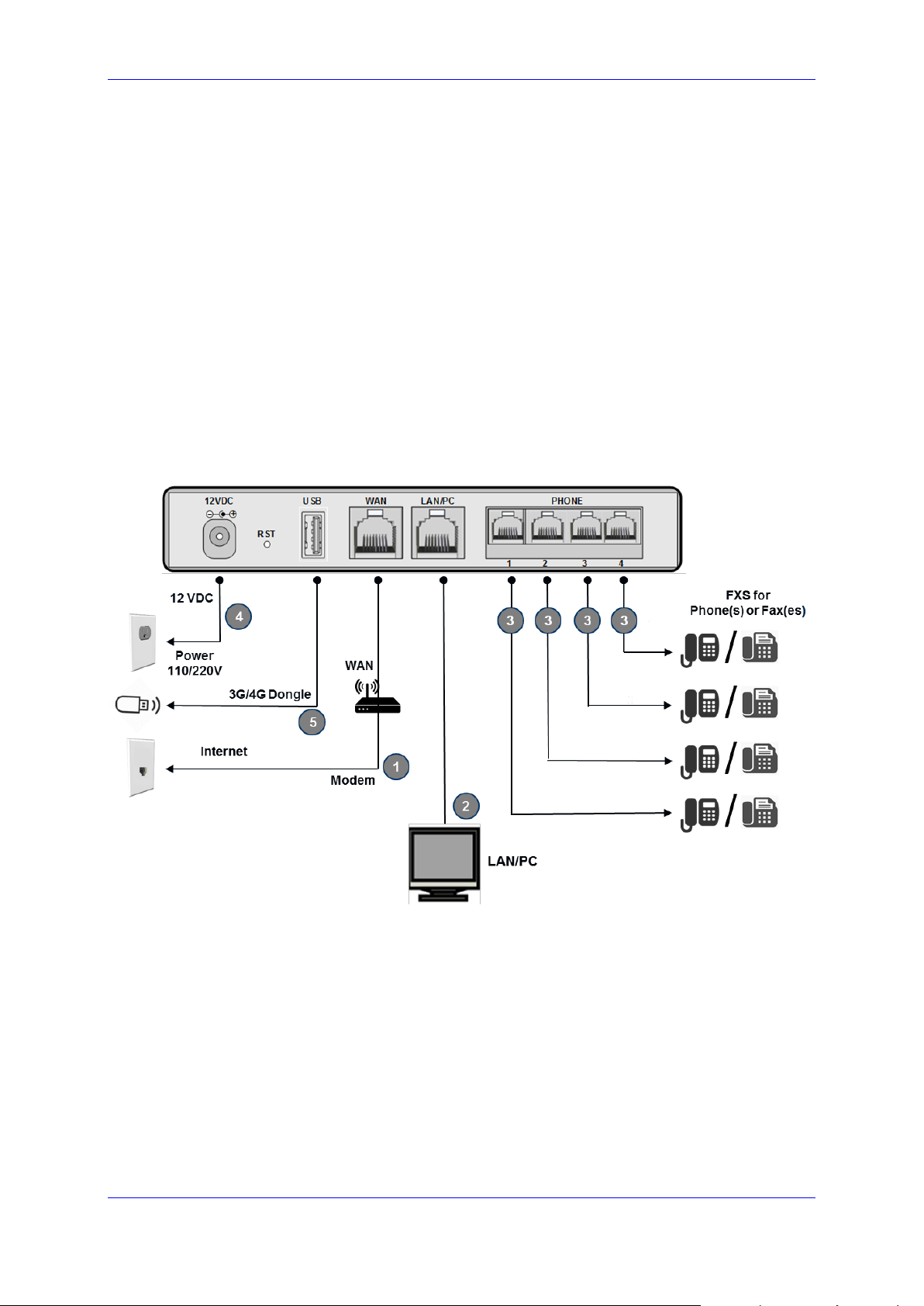
2 Cabling the MP-20x Telephone Adapter
The procedure below describes how to cable the MP-20x.
➢ To cable the MP-20x:
1. Connect the MP-20x’s Ethernet connector labeled WAN to your cable or DSL modem,
using the Ethernet cable.
2. Connect the MP-20x’s Ethernet connector labeled LAN/PC to your PC, using the
second Ethernet cable.
3. Connect the MP-20x’s telephone ports labeled PHONE to analog telephones/faxes,
using the RJ-11 telephone cables. (The number of telephone ports depends on your
MP-20x model.)
4. Connect MP-20x to a standard 110/220 VAC electrical wall outlet, using the AC/DC
power adapter; the POWER LED is lit (green) and when initialization completes
(~ 1 minute), the STATUS LED changes from red to green.
5. The USB port can be used as a secondary WAN (with 3G/4G dongles) or to connect a
disk-on-key, external hard disk drive or printer.
Figure 2-1: Cabling the Device (Example using MP-204R)
Page 14
User's Manual 14 Document #: LTRT-50619
MP-20x Telephone Adapter
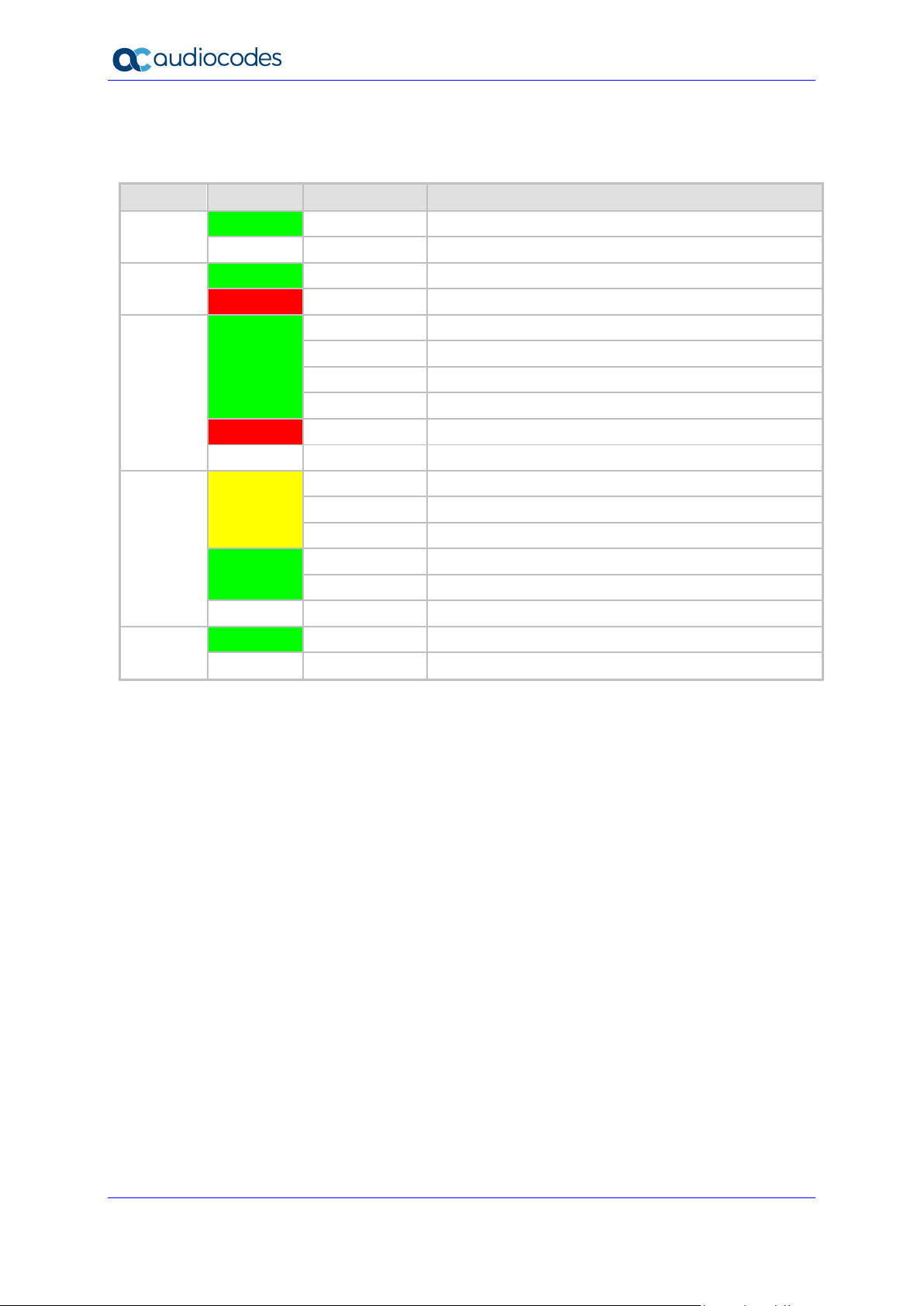
MP-20x provides LEDs on the front panel for indicating various operating status, as described in the
table below:
Table 2-1: MP-204B LEDs Description
LED
Color
State
Description
POWER
Green
On
Power received by MP-20x
-
Off
MP-20x has been powered off
STATUS
Green
On
System start-up successful
Red
On
Reboot (automatic, by default)
PHONE
1- 4
Green
Type 1 Blinking
Idle Proxy register ok
On
Off-hook
Type 2 Blinking
Phone ringing
Type 3 Blinking
Upgrade in process (all LEDs including STATUS LED)
Red
On
Idle Proxy register failed
-
Off
On-hook and not ringing, not using Proxy
LAN /
WAN
Yellow
Steady On
Connected at 10 Mbps
Steady On
Connected at 100 Mbps
Blinking
Activity - there is traffic on 10/100 Mbps
Green
Steady On
Connected at 1000 Mbps
Blinking
Activity - there is traffic on 1000 Mbps
-
Off
Disconnected
USB
Green
On
USB device is connected
-
Off
No USB device is connected
Page 15

User's Manual 3. Setting up a Network Connection
Version 4.5.0 15 MP-20x Telephone Adapter
3 Setting up a Network Connection
The procedure below describes how to set up a network connection.
➢ To set up a network connection:
1. Define your PC's network connection (refer to 'Defining Your PC's Network
Connection' on page 57).
2. Configure MP-20x's network connection (refer to 'Configuring the MP-20x's Network
Connection' on page 59).
3.1 Defining Your PC's Network Connection
Refer to MP-20x Telephone Adapter Quick Installation Guide for instructions relating to
installation on a Windows™ operating system.
Each network interface on the PC should either be configured with a statically defined IP
address and DNS address, or should be instructed to automatically obtain an IP address
using the Network DHCP server. MP-20x provides a DHCP server on its LAN and it is
recommended to configure your PC to obtain its IP and DNS server IPs automatically. This
configuration principle is identical but performed differently on each operating system.
◼ Refer to 'Configuring Computers Running on Windows 7' on page 57.
◼ Refer to 'Configuring Computers Running on Linux' on page 58.
Note: The setup procedure is in most cases unnecessary due to Windows' default
network settings. For example, the default DHCP setting in Windows 10 is 'client',
requiring no further modification. It is advisable however to follow the setup procedure
to verify that all communication parameters are valid and that the physical cable
connections are correct.
Page 16
User's Manual 16 Document #: LTRT-50619
MP-20x Telephone Adapter
Figure 3-1: IP and DNS Configuration
3.1.1 Configuring your PC Running Windows 10
➢ To configure your PC running Windows 10 for dynamic IP addressing:
1. Access 'Network Connections' from the Control Panel.
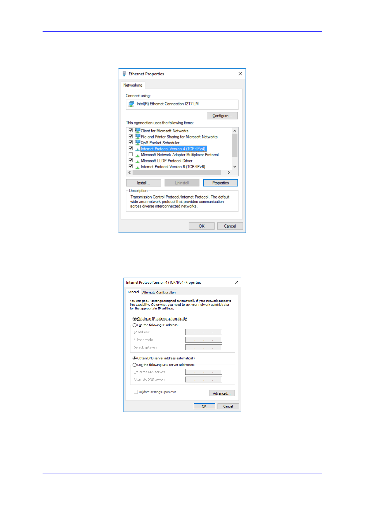
Figure 3-2: Ethernet Properties
Page 17
User's Manual 3. Setting up a Network Connection
Version 4.5.0 17 MP-20x Telephone Adapter
2. Right-click the Ethernet connection icon, and then select 'Properties'.
Figure 3-3: IPv4 Properties
3. Under the General tab, select the 'Internet Protocol (TCP/IP)' component, and click
the Properties button.
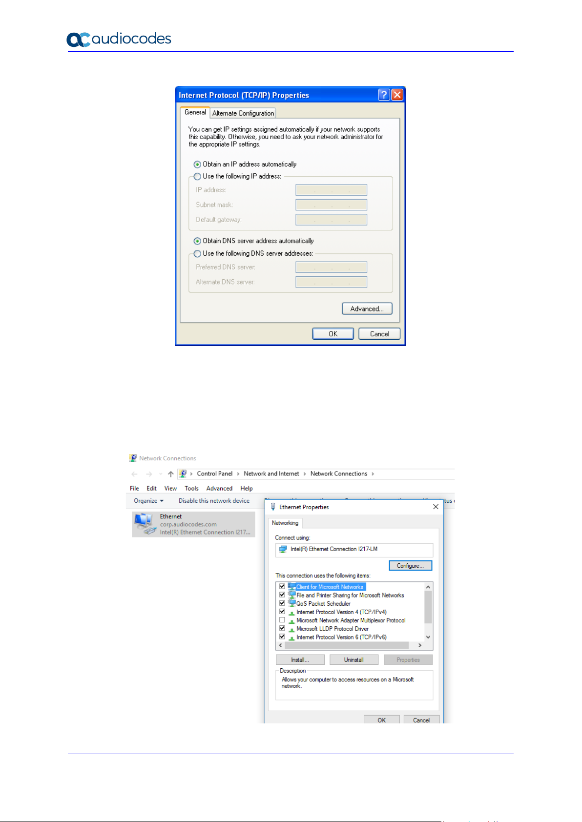
Figure 3-4: Obtain an IP Address Automatically
The 'Internet Protocol (TCP/IP)' properties window is displayed.
4. Select the 'Obtain an IP address automatically' radio button.
5. Select the 'Obtain DNS server address automatically' radio button.
6. Click OK to save the settings.
Page 18
User's Manual 18 Document #: LTRT-50619
MP-20x Telephone Adapter
3.1.2 Configuring your PC Running Linux
➢ To configure your PC running Linux for dynamic IP addressing:
1. Log in into the system as a super-user, by entering `su' at the prompt.
2. Type 'ifconfig' to display the network devices and allocated IP's.
3. Type 'pump -i <dev>', where <dev> is the network device name.
4. Type 'ifconfig' again to view the new allocated IP address.
5. Make sure no firewall is active on device <dev>.
3.2 Configuring the MP-20x's Network Connection
The Web-based management interface of MP-20x allows you to control the device's system
parameters. The interface is accessed through a Web browser. For detailed information on
MP-20x's Web-management interface, refer to 'Using the MP-20x's Web Interface' on page
64.
3.2.1 Logging in to MP-20x Web Interface
The procedure below describes how to login to MP-20x’s embedded Web interface.
➢ To log in:
1. Launch a Web browser on your PC.
2. With your PC connected directly to MP-20x, use URL http://mp20x.home to access the
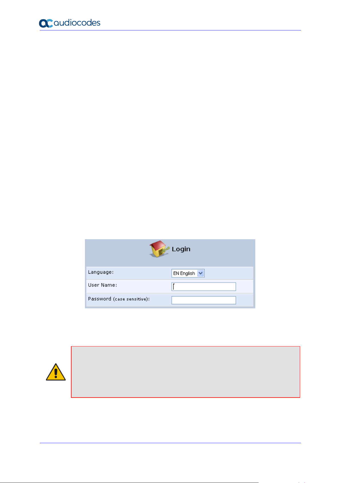
Web-based management interface; the ‘Login’ screen appears.
Figure 3-5: Logging In
3. In the 'User Name' field, enter your user name.
4. In the 'Password' field, enter your case-sensitive password.
5. Click OK; the 'Quick Setup' screen opens.
Notes:
• The default user name and password is "admin" (case-sensitive). However, it is
recommended to define a new password after your first login session (refer to
'Configuring Users' on page 327).
• If there’s inactivity after logging in, a new login becomes necessary after a lapse of
15 minutes.
Page 19
User's Manual 3. Setting up a Network Connection
Version 4.5.0 19 MP-20x Telephone Adapter
3.2.2 Configuring 'Quick Setup' Screen Parameters
The 'Quick Setup' screen enables the speedy, precise, and accurate configuration of your
Internet connection and other important parameters.
➢ To access the 'Quick Setup' screen:
1. From the sidebar menu, click the Quick Setup menu; the 'Quick Setup' screen
appear.
Figure 3-6: Quick Setup Screen
Note: End users are advised not to modify the section 'Administrator'. The screen
section applies to telephony carrier technicians.
2. In the 'Administrator' section of the 'Quick Setup' screen, specify the administrator's e-
mail in the 'E-mail Address' field. System alerts and notifications are sent to this
address.
3.2.2.1 Configuring Your Internet Connection
When subscribing to a broadband service, you should be aware of the method by which you
are connected to the Internet. Technical information regarding the properties of your Internet
connection should be provided by your Internet Service Provider (ISP). For example, your
ISP should inform you whether you are connected to the Internet using a static or dynamic
IP address, or what protocols, such as PPTP or PPPoE, you will be using to communicate
over the Internet.
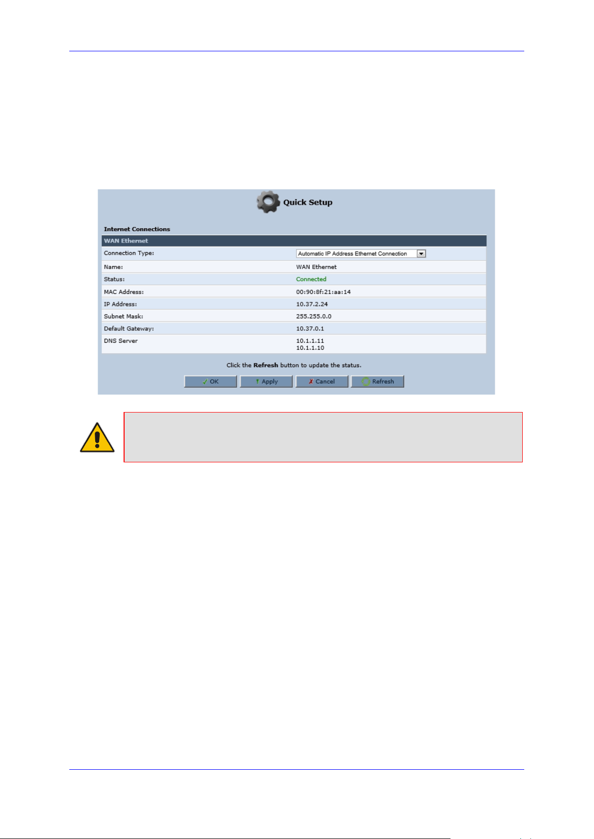
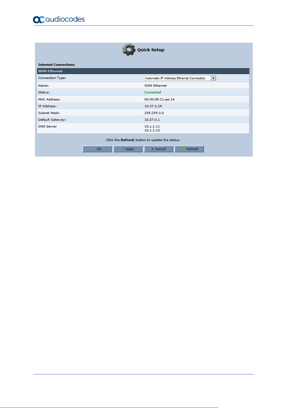
3.2.2.1.1 Automatic IP Address Ethernet Connection
'Automatic IP Address Ethernet Connection' is the default connection type in the 'Connection
Type' drop-down list.
Page 20
User's Manual 20 Document #: LTRT-50619
MP-20x Telephone Adapter
Figure 3-7: Internet Connection - Automatic IP Address Ethernet Connection
If left at the default, MP-20x obtains the WAN IP and DNS IP addresses from a DHCP server
on the WAN.
Page 21
User's Manual 3. Setting up a Network Connection
Version 4.5.0 21 MP-20x Telephone Adapter
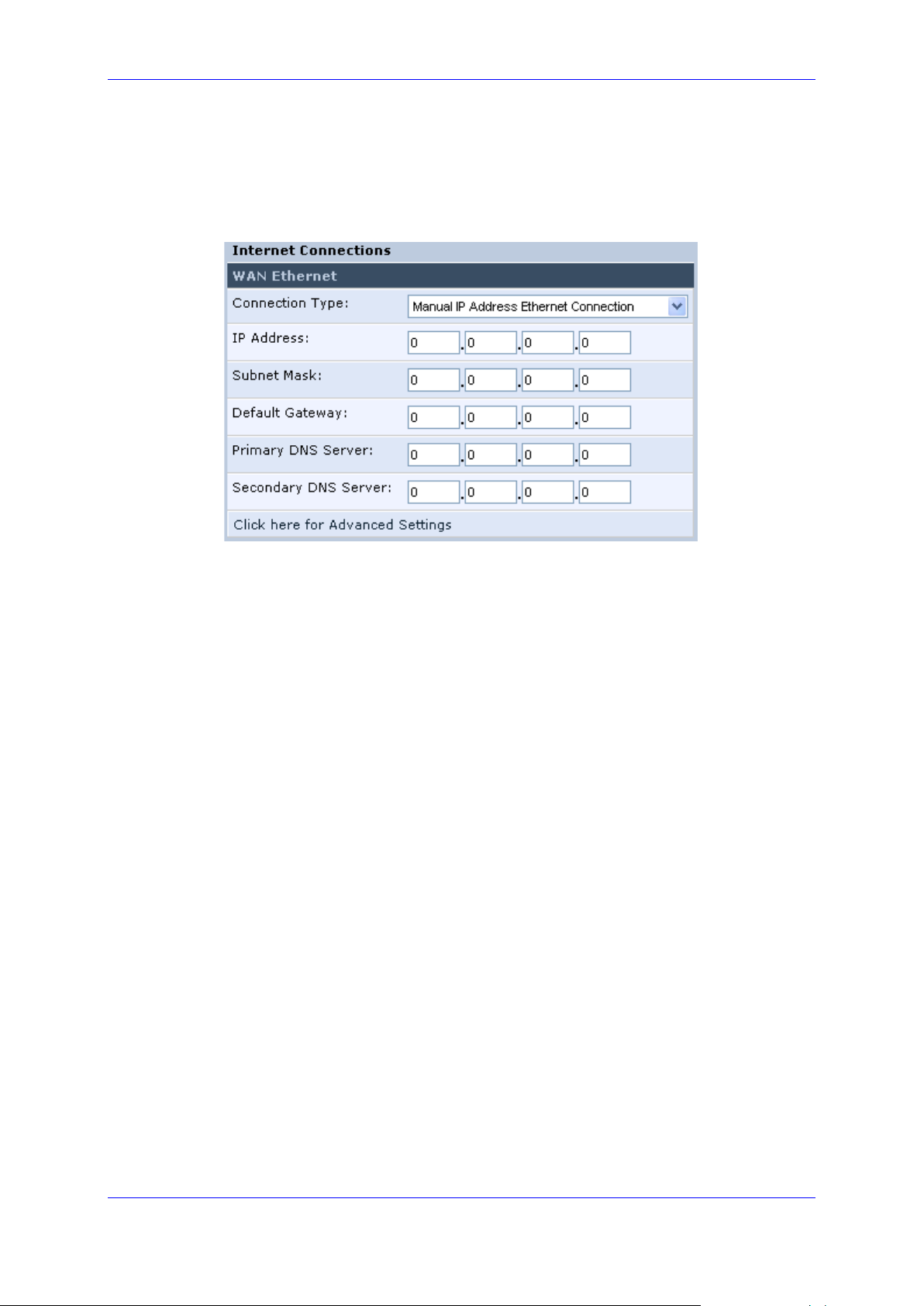
3.2.2.1.2 Manual IP Address Ethernet Connection
➢ To configure manual IP address connection:
1. From the 'Connection Type' drop-down list, select 'Manual IP Address Ethernet
Connection'.
Figure 3-8: Internet Connection - Manual IP Address Ethernet Connection
2. According to your ISP's instructions, specify the following parameters:
• IP address
• Subnet mask
• Default device
• Primary DNS server
• Secondary DNS server
Page 22
User's Manual 22 Document #: LTRT-50619
MP-20x Telephone Adapter
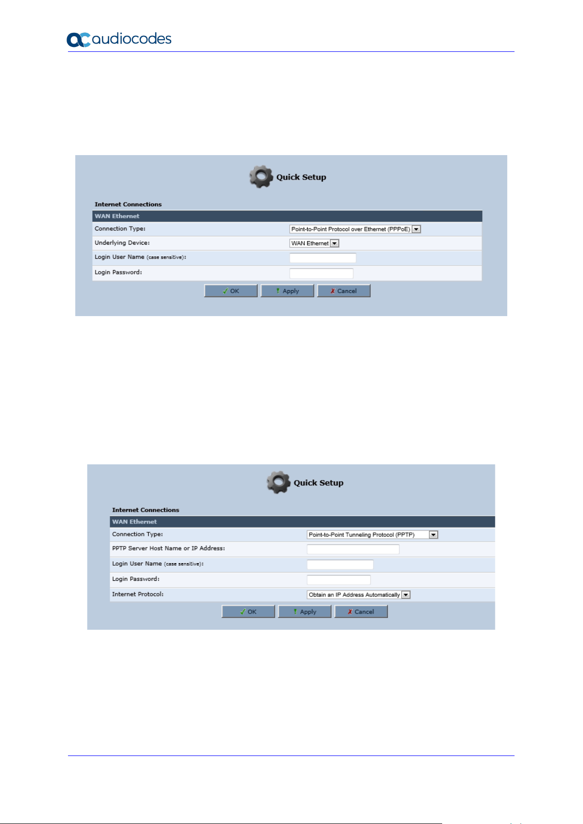
3.2.2.1.3 Point-to-Point Protocol over Ethernet (PPPoE)
➢ To configure PPPoE connection:
1. From the 'Connection Type' drop-down list, select 'Point-to-point protocol over
Ethernet (PPPoE)'.
Figure 3-9: Internet Connection - PPPoE
2. Your ISP should provide you with the following information:
• Login user name
• Login password
3.2.2.1.4 Point-to-Point Tunneling Protocol (PPTP)
➢ To configure PPTP connection:
1. From the 'Connection Type' drop-down list, select 'Point-to-Point Tunneling Protocol
(PPTP)'.
Figure 3-10: Internet Connection - Point-to-Point Tunneling Protocol
2. Your ISP should provide you with the following information:
• PPTP Server Host Name or IP Address
• Login user name
• Login password
Page 23
User's Manual 3. Setting up a Network Connection
Version 4.5.0 23 MP-20x Telephone Adapter
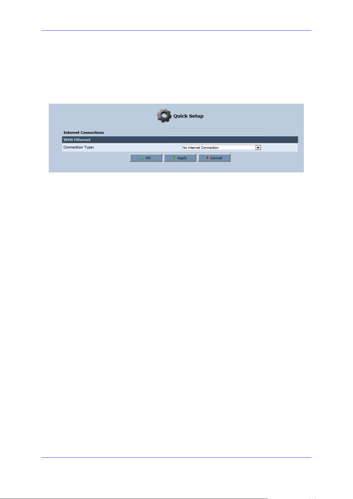
3.2.2.1.5 No Internet Connection
This option is if you do not have an Internet connection, or if you want to disable all existing
connections.
➢ To configure no Internet connection:
◼ From the 'Connection Type' drop-down list, select 'No Internet Connection'.
Figure 3-11: Internet Connection - No Internet Connection
Page 24
User's Manual 24 Document #: LTRT-50619
MP-20x Telephone Adapter
3.2.3 Configuring 3G/LTE USB Modem
Note: This sub-section is only applicable MP-204B.
The procedure below describes how to configure a WAN connection using a 3G/LTE cellular
modem. The 3G/LTE cellular modem is connected to the device’s physical port.
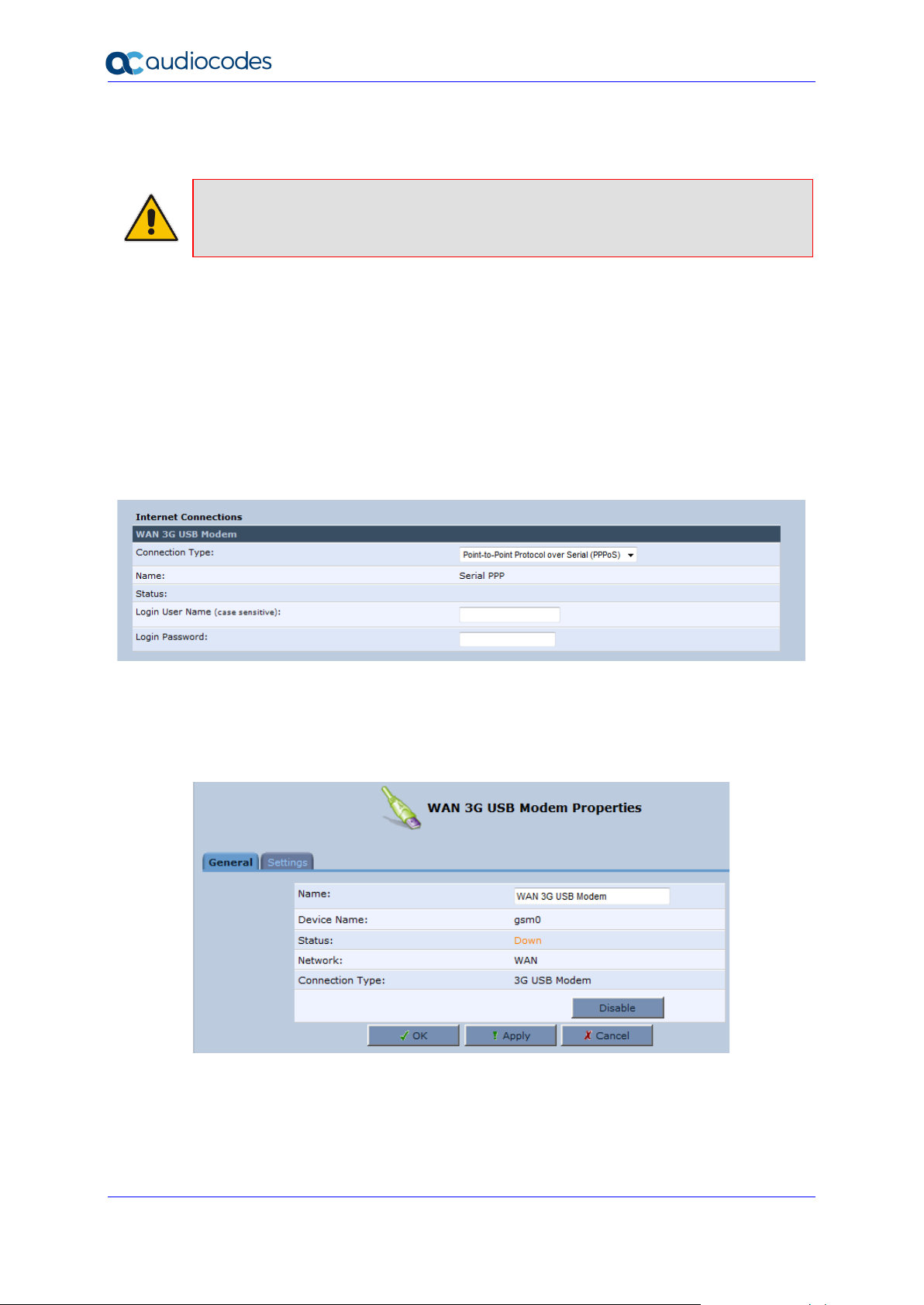
➢ To configure a WAN connection using a 3G/LTE cellular modem:
1. On the Quick Setup page under the WAN 3G USB Modem group, from the
'Connection Type' drop-down list, select the required connection type. The device
supports the following WAN 3G USB Modem connection types:
• Point-to-Point Protocol over Serial (PPPoS)
• Automatic IP Address over Serial
Figure 3-12: WAN 3G USB Modem
2. Enter your login user name and password.
3. Click OK.
4. On the 'Network Connections' screen, click the WAN 3G USB Modem hyperlink; the
'WAN 3G USB Modem Properties' screen appears.
Figure 3-13: WAN 3G USB Modem Properties
5. On the General tab, update the appropriate fields, and then click Apply.
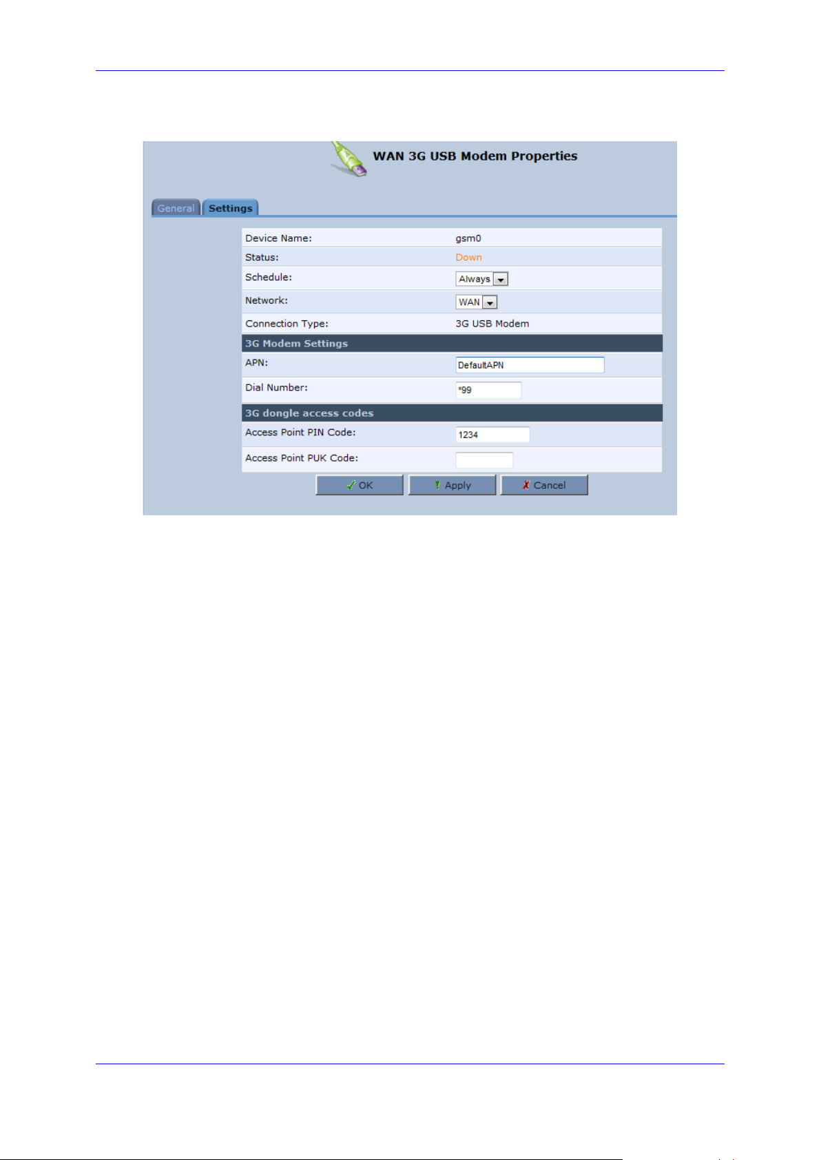
6. Click the Settings tab; the following screen appears.
Page 25
User's Manual 3. Setting up a Network Connection
Version 4.5.0 25 MP-20x Telephone Adapter
Figure 3-14: WAN 3G USB Modem Properties - Settings
7. Configure the appropriate fields as necessary.
8. In the ‘Access Point PIN Code’ field, enter the modem's personal identification number
(PIN), obtained from your Internet Service Provider.
9. In the 'Access Point PUK Code' field, enter the SIM’s PIN Unlock Key obtained from
your Internet Service Provider.
10. Click OK.
Page 26

User's Manual 26 Document #: LTRT-50619
MP-20x Telephone Adapter
This page is intentionally left blank.
Page 27
User's Manual 4. Device Quick Setup
Version 4.5.0 27 MP-20x Telephone Adapter
4 Device Quick Setup
The procedure below describes how to quickly configure your device for connecting it to the
Internet (WAN).
4.1 Preparing Initial Configuration
The procedure below describes how to prepare the initial configuration.
➢ To initially prepare for configuration:
1. Connect the cables as shown in Section 2 on page 13.
2. Power on the device.
3. From your browser, enter the device's default IP address (192.168.2.1).
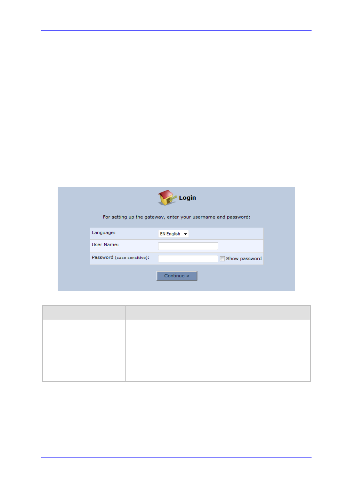
4. From the ‘Language’ drop-down list, select the desired language for the Web graphical
user interface (GUI) display.
5. In the 'User Name' and 'Password' fields, define a login username and password,
respectively and then click Continue.
Figure 4-1: Login Screen
Table 4-1: Login Parameters Description
Parameter
Description
User Name
Defines the username.
The valid value is a string of up to 64 lower case characters.
Note: The Web interface accepts upper case letters, but saves them
in lower case.
Password
Defines the user's password.
The valid value is a string of up to 64 characters. The Web interface
accepts all characters.
Page 28
User's Manual 28 Document #: LTRT-50619
MP-20x Telephone Adapter
4.2 Configuring SIP Signaling Protocol
The procedure below describes how to configure the SIP Signaling Protocol.
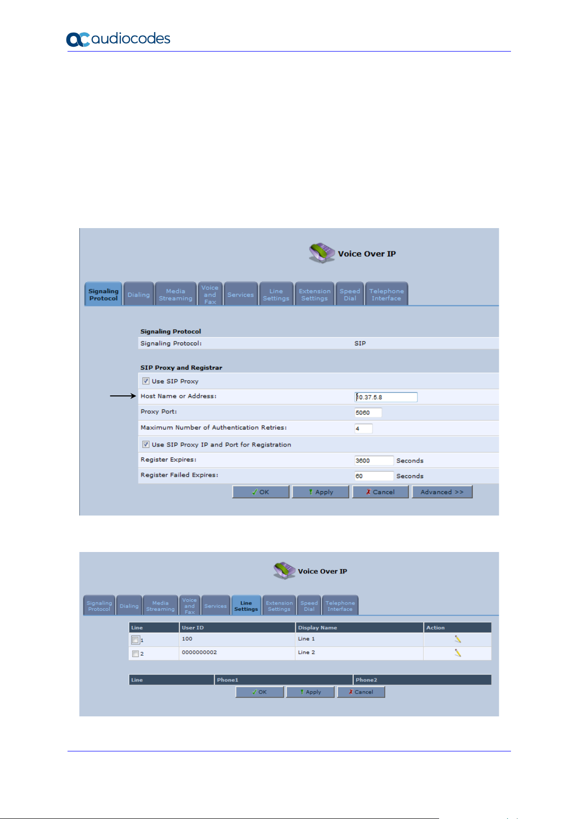
➢ To configure the SIP Signaling Protocol:
1. Click the ‘Voice Over IP’ menu in the side menu bar; the ‘Voice Over IP’ screen
appears.
2. On the ‘Signaling Protocol’ page, enter the Host Name or Address.
3. Under the SIP Proxy and Registrar group, select the 'Use SIP Proxy IP and Port for
Registration' check box.
4. Enter the Host Name as shown in the following screen:
Figure 4-2: Signaling Protocol
5. Click the Line Settings tab; the following screen appears.
Figure 4-3: Line Settings
Page 29
User's Manual 4. Device Quick Setup
Version 4.5.0 29 MP-20x Telephone Adapter
6. Select the One Line Configuration; the table lists the lines according to the selected
line configuration mode.
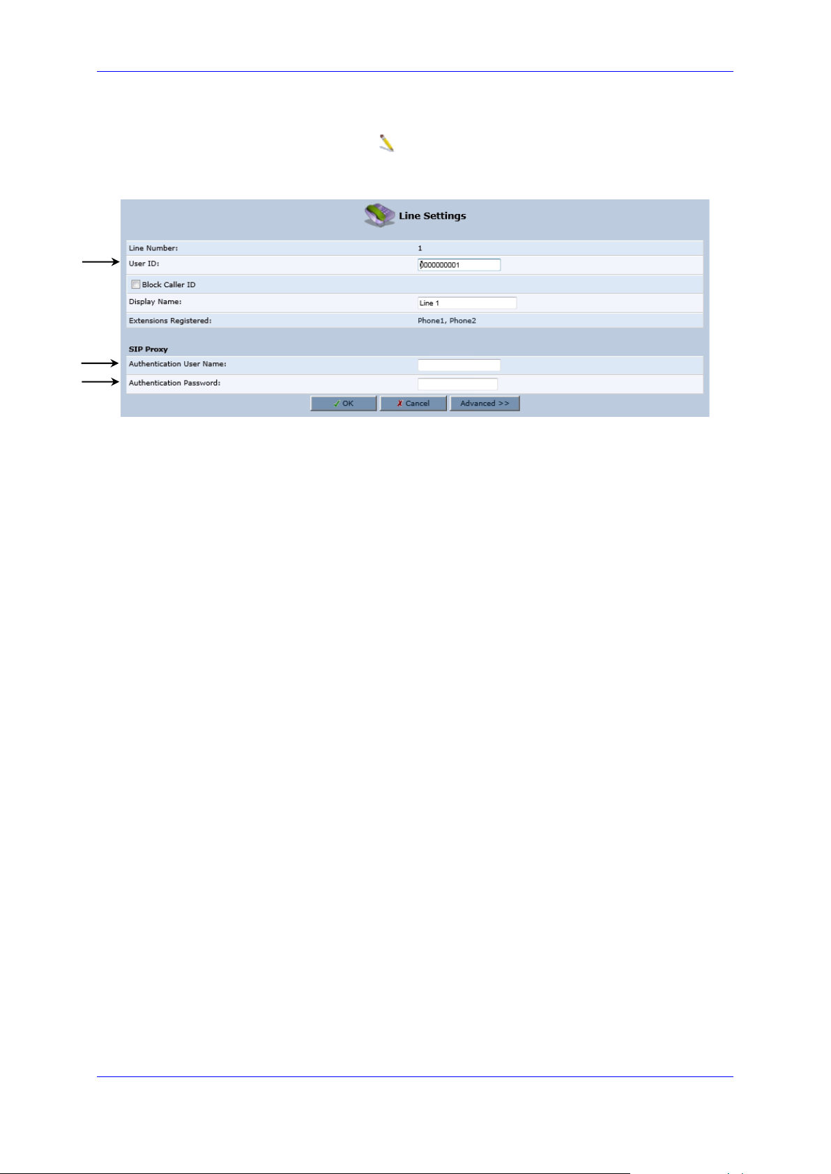
7. Click the corresponding Edit icon to configure the line; the following screen
appears:
Figure 4-4: Line Settings
8. In the ‘User ID’ field, enter the phone's VoIP user ID used for identification to initiate
and accept calls.
9. In the ‘Authentication User Name’ field, enter the user name received from your VoIP
service provider.
10. In the ‘Authentication Password’ field, enter the password received from your VoIP
service provider.
11. Click OK.
Page 30

User's Manual 30 Document #: LTRT-50619
MP-20x Telephone Adapter
This page is intentionally left blank.
Page 31

User's Manual 5. Getting Started with the Web Interface
Version 4.5.0 31 MP-20x Telephone Adapter
5 Getting Started with the Web Interface
The device's embedded Web server (Web interface) provides a user-friendly Web-based
management tool that allows you to configure and monitor the device. The procedures below
describe how to access, navigate in, and configure parameters with the Web interface.
5.1 Logging into the Web Interface
The procedure below describes how to log in to the device's Web interface.
➢ To log in to the device's Web interface:
1. Connect a PC directly to the LAN port (labeled LAN 1) of the device.
2. On your PC, open a Web browser (e.g., Internet Explorer) and in the URL field, enter
http://mp202.home (or 192.168.2.1). If your device is already connected to the
network and you know its IP address, then enter its IP address instead. The ‘Login’
screen appears:
Figure 5-1: Login Screen
3. From the ‘Language’ drop-down list, select the desired language for the Web graphical
user interface (GUI) display.
4. In the 'User Name' and 'Password' fields, define a login username and password,
respectively. This is applicable only if this is your first time that you are logging in to
the Web interface. If you have logged in before, then enter the username and
password that you defined previously.
5. Click Continue; the ‘Quick Setup’ screen appears, allowing you to quickly set up an
Internet connection (as described in Chapter 6 on page 55).
Notes:
• The default username and password is "admin" (case-sensitive).
• If you wish to view the entered password (instead of asterisks), then select the
‘Show password’ check box.
• You can later change the username and password as described in Section 5.4 on
page 327.
• If the Web interface is inactive for 15 minutes after logging in, the ‘Login’ screen
appears again, prompting you to re-login.
Page 32

User's Manual 32 Document #: LTRT-50619
MP-20x Telephone Adapter
5.2 Menu Bar Description
The Web interface screens are conveniently grouped into related themes under specific
menus. These menus are in the menu bar. The table below describes these menus.
Table 5-1: Menu Description
Menu
Description
Home
Displays the Map View (refer to Chapter 6 on page 55).
Quick Setup
Displays the 'Quick Setup' screen for quickly setting up an Internet connection
with the device (see Section 8.1 on page 59).
Network
Connections
Displays the 'Network Connections' screen for configuring network connections:
▪ LAN (see Section 12.2 on page 137)
▪ WAN (see Chapter 12 on page 127)
▪ VLANs (see Section 12.4 on page 152)
▪ LAN-WAN bridging (see Section 12.5 on page 160)
Security
Displays the 'Security' screen for configuring security-related features such as
Website restrictions (see Chapter 16 on page 241).
Voice Over IP
Displays the 'Voice Over IP' screen for configuring the VoIP parameters to use the
device's VoIP functionality to place and receive calls over the Internet using a
standard telephone set.
QoS
Displays the 'Quality of Service' screen for configuring Quality of Service (QoS)
for the device (see Chapter 11 on page 109).
Advanced
Displays the 'Advanced' screen for configuring system parameters (e.g., DHCP
server and DNS) and for administrative functions (e.g., changing password,
setting date and time, and upgrading the system).
Icon
Name
Description
3G USB
Displays 3G dongle status and 3G dongle
access codes (see Section 3.2.3 page 24).
About MP20x
Displays technical information about the
device, including version number (see
Section 21.2 on page 305).
Certificates
Manages digital certificates (see Section
15.3 on page 212).
Configuration
File
Loads the Configuration File to the device
(see Section 21.4 on page 309).
Note: You can hide the Configuration File
icon, by running the following CLI
command in a Telnet session with the
device:
conf_set
rmt_config/hide_config_file_page
1. This is useful, for example, in scenarios
where you want to prevent a user
accessing the Web interface to change the
configuration file.
Page 33

User's Manual 5. Getting Started with the Web Interface
Version 4.5.0 33 MP-20x Telephone Adapter
Menu
Description
DNS Server
Alias a dynamic IP address to a static
hostname (see Section 17.2 on page 273).
Diagnostics
Performs networking diagnostics (see
Section 22.1 on page 331).
Feature Key
Enables new features on the Feature Key
(see Section 21.1 on page 303).
File Server
Creates a file server on the device (see
Section 14.1 on page 177).
Firmware
Upgrade
Upgrades the device's firmware (see
Section 21.5 on page 319).
IP Address
Distribution
Modifies the DHCP server for each LAN
device and displays a list of DHCP clients
in the local network (see Section 17.1 on
page 267).
Installation
Wizard
Guides you through your Internet
connection, to help you subscribe for
services that are available to you as an
MP-202B user (see Section 17.7 on page
283).
Media Sharing
Enables media sharing on local networks
and in all folders (see Section 20 on page
299).
Network
Objects
Defines groups of LAN devices for system
rules (see Section 5.6.2 on page 51).
PPPoE Relay
Enables PPPoE relay on the device (see
Section 17.5 on page 281).
PacketSmart
Configuration
Enables PacketSmart Configuration (see
Section 19 on page 291).
Personal
Domain Name
(Dynamic
DNS)
Displays and modifies the DNS hosts table
(see Section 17.2 on page 273).
Print Server
Shares a LAN printer (see Section 14.2 on
page 180).
Protocols
Manages protocols (see Section 5.6.3 on
page 53).
Page 34

User's Manual 34 Document #: LTRT-50619
MP-20x Telephone Adapter
Menu
Description
Reboot
Restarts MP-20x (see Section 21.7 on
page 328).
Regional
Settings
Modifies the regional settings (see Section
17.6 on page 282).
Remote
Administration
Configures remote administration
privileges (see Section 15.2 on page 208).
Restore
Factory
Settings
Restores default factory settings (see
Section 21.8 on page 329).
Routing
Manages routing policies (see Section 17.4
on page 278).
Scheduler
Defines time segments for system rules
(see Section 5.6.1 on page 49).
Simple
Network
Management
Protocol
(SNMP)
Configures the device's SNMP agent (see
Section 15.2 on page 208).
System
Settings
Modifies administrator settings, including
the device's host name (see Section 17.5
on page 281).
Time Settings
Configures the local date and time (see
Section 21.3 on page 306).
Universal Plug
and Play
Configures Universal Plug-and-Play
(UPnP) parameters (see Section 18.1 on
page 285).
Users
Configures Users (see Section 5.4 on page
36).
System
Monitoring
Displays the 'System Monitoring' screen for viewing various statuses such as
network and traffic statistics (see Section 22.3 on page 343 ).
Logout
Logs off the device's Web interface.
Page 35

User's Manual 5. Getting Started with the Web Interface
Version 4.5.0 35 MP-20x Telephone Adapter
5.3 Managing Tables
Tables appear throughout the Web interface for configuring the device. This section
describes the how to use these tables to configure the device.
The figure below displays a typical table in the Web interface:
Figure 5-2: Typical Table Structure
Each table row denotes an entry in the table. The table also provides 'Action' icons for
performing various tasks. These icons are described in the table below.
Table 5-2: Table Action Icons Description
Action Icon
Name
Description
New
Adds a new row to the table or opens another screen for
adding an entry.
Edit
Modifies a row entry in the table.
Remove
Deletes a row entry in the table.
Download
Downloads a file to a folder on your computer.
Page 36

User's Manual 36 Document #: LTRT-50619
MP-20x Telephone Adapter
5.4 Configuring Users
The 'Users' screen allows you to add new users and assign login usernames and passwords.
You may also group users according to your preferences. The default user is "Administrator"
with "admin" (case-sensitive) as the username and password.
➢ To configure users:
1. On the 'Advanced' screen, click the Users icon; the 'Users' screen appears.
Figure 5-3: Users Screen
2. In the Users table, click the New User icon; the 'Users Settings' screen appears.
Page 37

User's Manual 5. Getting Started with the Web Interface
Version 4.5.0 37 MP-20x Telephone Adapter
Figure 5-4: Users Settings Screen
3. Add a new user by configuring the following fields:
a. Full Name: Enter a remote user's full name.
b. User Name: Enter a user name to access your home network.
c. New Password: Enter a new password for the remote user. If you do not want to
change the remote user's password leave this field empty.
d. Retype New Password: If a new password was assigned, enter it again to verify
correctness.
e. Role: User’s role indicating privilege level, where “admin” possesses all
privileges.
f. Access Level – Read Only: Select this check box if you want this user to have
read-only privileges.
g. Disk Management: By default, this option is selected. When activated, it creates
a directory for the user in the 'Home' directory of the system storage area. This
directory is necessary when using various applications such as the mail server.
Page 38

User's Manual 38 Document #: LTRT-50619
MP-20x Telephone Adapter
h. Email Notification: You can use email notification to receive indications of
system events for a predefined severity classification. The available types of
events are 'System' or 'Security' events. The available severity of events is 'Error',
'Warning' and 'Information. If the 'Information' level is selected, the user receives
notification of the 'Information', 'Warning' and 'Error' events. If the 'Warning' level
is selected, the user receives notification of the 'Warning' and 'Error' events etc.
Click here to configure notification mail server: This opens the ‘System
Settings’ screen (see Section 17.5 on page 281) where you can define an
outgoing mail server.
Notification Address: user’s email address.
System Notify Level: By default, the 'None' option is selected, which means
that the device does not send notifications to a remote host. To activate the
feature, select one of the following notification types:
✓ Error
✓ Warning
✓ Information
Security Notify Level: The remote security notification level can be one of
the following:
✓ None
✓ Error
✓ Warning
✓ Information
4. Click OK.
The following is an example of the relevant Telnet parameters:
rg_conf/admin/user/0/enabled=1
rg_conf/admin/user/0/username=admin
rg_conf/admin/user/0/full_name=Administrator
rg_conf/admin/user/0/email=NULL
rg_conf/admin/user/0/notify_level/0=none
rg_conf/admin/user/0/notify_level/1=none
rg_conf/admin/user/0/directory=1
rg_conf/admin/user/0/role=admin
rg_conf/admin/user/1/enabled=1
rg_conf/admin/user/1/username=home
rg_conf/admin/user/1/password=&be;c&5c;&b5;
rg_conf/admin/user/1/full_name=Home user
rg_conf/admin/user/1/email=NULL
rg_conf/admin/user/1/notify_level/0=none
rg_conf/admin/user/1/notify_level/1=none
rg_conf/admin/user/1/directory=1
rg_conf/admin/user/1/role=home
Page 39

User's Manual 5. Getting Started with the Web Interface
Version 4.5.0 39 MP-20x Telephone Adapter
➢ To configure user groups:
1. On the 'Users' screen, under the Groups group, click New Group icon; the 'Group
Settings' screen appears.
Figure 5-5: Group Settings Screen
2. In the 'Name' field enter a name for the group.
3. In the 'Description' field, enter a brief description of this group.
4. In the 'Group Members' list, select the users that you want to assign to this group.
5. Click OK.
The following is an example of the relevant Telnet parameter:
rg_conf/admin/group/0/name=Users
5.4.1 Web User Permissions
This sub-section describes the following commands for viewing and changing user
permissions via Telnet:
◼ Print commands
◼ Set commands
5.4.1.1 Print Commands
This section describes the Print commands used for viewing and changing user’s
permissions.
5.4.1.1.1 Current User Roles
The example below shows the Print command for viewing current users. Note that each
user’s role is bolded.
MP264> conf
conf> print admin/user
(user
(0
(enabled(1))
(username(admin))
(full_name(Administrator))
Page 40

User's Manual 40 Document #: LTRT-50619
MP-20x Telephone Adapter
(email())
(notify_level
(0(none))
(1(none))
)
(directory(1))
(role(admin))
(password(&b7;X&5c;&b9;&a2;))
)
(1
(enabled(1))
(username(home))
(password(&be;c&5c;&b5;))
(full_name(Home user))
(email())
(notify_level
(0(none))
(1(none))
)
(directory(1))
(role(home))
)
)
5.4.1.1.2 Role and Permissions
The example below shows the Print command for viewing existing permissions per role.
Note that each role has default privileges.
MP264> conf
conf> print admin/role
(role
(0
(name(anonymous))
(permission(00000000c000000000000000000000000000000000000000))
)
(1
(name(guest))
(permission(00000000c000000000000000000000000000000000000000))
)
(2
(name(home))
(permission(c3ff3ccffc0f0f003000f303300cc30c3ffffffc3fc00000))
(create_role
(guest(1))
(home(1))
)
)
(3
(name(admin))
(permission(fffffffffffffffffcffffffffcfcfccfffffffc3fffff00))
(create_role
(admin(1))
Page 41

User's Manual 5. Getting Started with the Web Interface
Version 4.5.0 41 MP-20x Telephone Adapter
(basic(1))
(advanced(1))
)
)
(4
(name(super))
(permission(ffffffffffffffffffffffffffffffffffffffffffffff00))
(create_role
(guest(1))
(home(1))
(admin(1))
(super(1))
(basic(1))
(advanced(1))
)
)
(5
(name(basic))
(permission(c0000003c000000000000000000000000000000000000000))
)
(6
(name(advanced))
(permission(c0000003c0000000000c0000000000000000000000000000))
)
)
Returned 0
conf>
5.4.1.1.3 Permission Attributes per Role
The example below shows the Print command for viewing the permission attributes. In this
example, the permission attributes for the Advanced role are displayed.
conf> print_permission admin/role/3/permission
(admin/role/3/permission
(access_wbm(rw))
(access_serial_cli(rw))
(access_telnet(rw))
(access_fs(rw))
(access_ftp(rw))
(access_mail(rw))
(access_wlan(rw))
(access_ssl_vpn(rw))
(access_ssh(rw))
(access_vpn(rw))
(access_printer(rw))
(access_rmt_mng(rw))
(access_http_auth(rw))
(access_ppp(rw))
(access_rmt_upd_tftp(rw))
(default(rw))
(all(rw))
Page 42

User's Manual 42 Document #: LTRT-50619
MP-20x Telephone Adapter
(reboot(rw))
(restore_factory(rw))
(firmware_upgrade(rw))
(upload_conf(rw))
(dump_conf(rw))
(ddns(rw))
(firewall_basic(rw))
(firewall_advanced(rw))
(firewall_nat(rw))
(date_time(rw))
(qos(rw))
(qos_advanced(rw))
(docsis_advanced(rw))
(system_monitor(rw))
(system_settings(rw))
(objects_rules(rw))
(remote_admin(rw))
(diagnostics(rw))
(mac_clone(--))
(radius_client(rw))
(radius_server(rw))
(internet_connection(rw))
(network_connections(rw))
(disk_mng(rw))
(file_server(rw))
(print_server(rw))
(ssl_vpn(rw))
(backup(rw))
(ssh(rw))
(routing(rw))
(voice_basic(rw))
(voice_admin(rw))
(groups(rw))
(page_about(rw))
(page_advanced(rw))
(advanced_sys_overview(rw))
(remote_admin_jrmp(--))
(virtual_ap(rw))
(dns(rw))
(new_connection(rw))
(block_ip_fragments(--))
(tab_local_network(rw))
(wbm_add_user(rw))
(website_restrictions(rw))
(entfy(--))
(clock_set(rw))
(wlan_inter_client(--))
(qos_stats(rw))
(conn_troubleshoot(rw))
(dhcps(rw))
(dlm(rw))
Page 43

User's Manual 5. Getting Started with the Web Interface
Version 4.5.0 43 MP-20x Telephone Adapter
(nation_zone(rw))
(dhcp(rw))
(port_forwarding(rw))
(users(rw))
(upnp(rw))
(certificates(rw))
(page_map(rw))
(page_quick_setup_advanced(rw))
(dmz_host(rw))
(wireless_basic(rw))
(wireless_admin(rw))
(wireless_advanced(--))
(change_password(--))
(network_connections_common(rw))
(port_forwarding_advanced(rw))
(primus_advanced(rw))
(packetsmart(rw))
(ipsec(rw))
(installation_wizard(rw))
(media_sharing(rw))
(pptp_server(rw))
(parental_control(rw))
(watchdog(rw))
)
Returned 0
conf>
- Set Commands
conf> print_permission admin/role/3/permission
(admin/role/3/permission
(access_wbm(rw))
(access_serial_cli(rw))
(access_telnet(rw))
(access_fs(rw))
(access_ftp(rw))
(access_mail(rw))
(access_wlan(rw))
(access_ssl_vpn(rw))
(access_ssh(rw))
(access_vpn(rw))
(access_printer(rw))
(access_rmt_mng(rw))
(access_http_auth(rw))
(access_ppp(rw))
(access_rmt_upd_tftp(rw))
(default(rw))
(all(rw))
(reboot(rw))
Page 44

User's Manual 44 Document #: LTRT-50619
MP-20x Telephone Adapter
(restore_factory(rw))
(firmware_upgrade(rw))
(upload_conf(rw))
(dump_conf(rw))
(ddns(rw))
(firewall_basic(rw))
(firewall_advanced(rw))
(firewall_nat(rw))
(date_time(rw))
(qos(rw))
(qos_advanced(rw))
(docsis_advanced(rw))
(system_monitor(rw))
(system_settings(rw))
(objects_rules(rw))
(remote_admin(rw))
(diagnostics(rw))
(mac_clone(--))
(radius_client(rw))
(radius_server(rw))
(internet_connection(rw))
(network_connections(rw))
(disk_mng(rw))
(file_server(rw))
(print_server(rw))
(ssl_vpn(rw))
(backup(rw))
(ssh(rw))
(routing(rw))
(voice_basic(rw))
(voice_admin(rw))
(groups(rw))
(page_about(rw))
(page_advanced(rw))
(advanced_sys_overview(rw))
(remote_admin_jrmp(--))
(virtual_ap(rw))
(dns(rw))
(new_connection(rw))
(block_ip_fragments(--))
(tab_local_network(rw))
(wbm_add_user(rw))
(website_restrictions(rw))
(entfy(--))
(clock_set(rw))
(wlan_inter_client(--))
(qos_stats(rw))
(conn_troubleshoot(rw))
(dhcps(rw))
(dlm(rw))
(nation_zone(rw))
Page 45

User's Manual 5. Getting Started with the Web Interface
Version 4.5.0 45 MP-20x Telephone Adapter
(dhcp(rw))
(port_forwarding(rw))
(users(rw))
(upnp(rw))
(certificates(rw))
(page_map(rw))
(page_quick_setup_advanced(rw))
(dmz_host(rw))
(wireless_basic(rw))
(wireless_admin(rw))
(wireless_advanced(--))
(change_password(--))
(network_connections_common(rw))
(port_forwarding_advanced(rw))
(primus_advanced(rw))
(packetsmart(rw))
(ipsec(rw))
(installation_wizard(rw))
(media_sharing(rw))
(pptp_server(rw))
(parental_control(rw))
(watchdog(rw))
)
Returned 0
conf>
conf>
conf>
conf>
conf>
conf>
conf>
conf>
conf>
conf> set_permission admin/role/3/permission page_map --
Returned 0
conf> reconf 1
Returned 0
conf> print_permission admin/role/3/permission
(admin/role/3/permission
(access_wbm(rw))
(access_serial_cli(rw))
(access_telnet(rw))
(access_fs(rw))
(access_ftp(rw))
(access_mail(rw))
(access_wlan(rw))
(access_ssl_vpn(rw))
(access_ssh(rw))
Page 46

User's Manual 46 Document #: LTRT-50619
MP-20x Telephone Adapter
(access_vpn(rw))
(access_printer(rw))
(access_rmt_mng(rw))
(access_http_auth(rw))
(access_ppp(rw))
(access_rmt_upd_tftp(rw))
(default(rw))
(all(rw))
(reboot(rw))
(restore_factory(rw))
(firmware_upgrade(rw))
(upload_conf(rw))
(dump_conf(rw))
(ddns(rw))
(firewall_basic(rw))
(firewall_advanced(rw))
(firewall_nat(rw))
(date_time(rw))
(qos(rw))
(qos_advanced(rw))
(docsis_advanced(rw))
(system_monitor(rw))
(system_settings(rw))
(objects_rules(rw))
(remote_admin(rw))
(diagnostics(rw))
(mac_clone(--))
(radius_client(rw))
(radius_server(rw))
(internet_connection(rw))
(network_connections(rw))
(disk_mng(rw))
(file_server(rw))
(print_server(rw))
(ssl_vpn(rw))
(backup(rw))
(ssh(rw))
(routing(rw))
(voice_basic(rw))
(voice_admin(rw))
(groups(rw))
(page_about(rw))
(page_advanced(rw))
(advanced_sys_overview(rw))
(remote_admin_jrmp(--))
(virtual_ap(rw))
(dns(rw))
(new_connection(rw))
(block_ip_fragments(--))
(tab_local_network(rw))
(wbm_add_user(rw))
Page 47

User's Manual 5. Getting Started with the Web Interface
Version 4.5.0 47 MP-20x Telephone Adapter
(website_restrictions(rw))
(entfy(--))
(clock_set(rw))
(wlan_inter_client(--))
(qos_stats(rw))
(conn_troubleshoot(rw))
(dhcps(rw))
(dlm(rw))
(nation_zone(rw))
(dhcp(rw))
(port_forwarding(rw))
(users(rw))
(upnp(rw))
(certificates(rw))
(page_map(--))
(page_quick_setup_advanced(rw))
(dmz_host(rw))
(wireless_basic(rw))
(wireless_admin(rw))
(wireless_advanced(--))
(change_password(--))
(network_connections_common(rw))
(port_forwarding_advanced(rw))
(primus_advanced(rw))
(packetsmart(rw))
(ipsec(rw))
(installation_wizard(rw))
(media_sharing(rw))
(pptp_server(rw))
(parental_control(rw))
(watchdog(rw))
)
Returned 0
conf>
Page 48

User's Manual 48 Document #: LTRT-50619
MP-20x Telephone Adapter
5.5 Set Commands
This section describes the Set commands used for viewing and changing the user’s
permissions. The example below shows how to enable the 'Advanced' menu page and then
to enable the Reboot option under the 'Advanced' page.
conf> set_permission admin/role/6/permission page_advanced 1
Returned 0
conf> reconf 1
Returned 0
conf> set_permission admin/role/6/permission reboot 1
Returned 0
conf> reconf 1
Returned 0
conf>
Note: In some cases, you need to enable specific pages prior to others. For
example, enabling “reboot” will not be displayed, before “page_advanced” is
enabled.
Page 49

User's Manual 5. Getting Started with the Web Interface
Version 4.5.0 49 MP-20x Telephone Adapter
5.6 Associated Elements
You can define certain elements and then use them later when configuring various features
throughout the Web interface. This is very convenient in that it eliminates the need to reconfigure the same element, especially if used in multiple configuration areas. These
elements include the following:
◼ Scheduler Rules – see Section 5.6.1 on page 49
◼ Network Objects – see Section 5.6.2 on page 51
◼ Protocols – see Section 5.6.3 on page 53
5.6.1 Configuring Scheduler Rules
Scheduler rules are used for limiting the activation of firewall rules to specific time periods,
specified in days of the week, and hours.
➢ To define a Rule:
1. On the 'Advanced' screen, click the Scheduler icon; the 'Scheduler Rules'
screen appears.
Figure 5-6: Scheduler Rules Screen
2. Click the New icon; the 'Edit Scheduler Rule' screen appears.
Figure 5-7: Edit Scheduler Rule Screen
3. In the 'Name' field, specify a name for the scheduler rule.
4. Under the Rule Activity Settings group, specify if the rule is active or inactive during
the designated time period, by selecting the appropriate check box.
5. Click the New icon to define the time segment to which the rule applies; the 'Edit
Time Segment' screen appears.
Page 50

User's Manual 50 Document #: LTRT-50619
MP-20x Telephone Adapter
Figure 5-8: Edit Time Segment Screen
a. Under the Days of Week group, select the days of the week for which you want
the rule to be active.
b. In the Hours Range table, click the New icon to define an active or inactive
hourly range; the ‘Edit Hour Range’ screen appears.
Figure 5-9: Edit Hour Range Screen
c. In the ‘Start Time’ and ‘End Time’ field, enter the time interval in which the
scheduler rule is active or inactive.
6. Click OK to save the settings.
Page 51

User's Manual 5. Getting Started with the Web Interface
Version 4.5.0 51 MP-20x Telephone Adapter
5.6.2 Configuring Network Objects
Defining network objects is a method used to logically define a set of LAN hosts, according
to one or more MAC address, IP address, and host name. Defining such a group can assist
when configuring other system rules. For example, you can use network objects to apply
security rules based on host names instead of IP addresses. This may be useful, since IP
addresses change from time to time. Moreover, it is possible to define network objects
according to MAC addresses, making rule application more persistent against network
configuration settings.
➢ To define a network object:
1. On the 'Advanced' screen, click the Network Objects icon; the 'Network
Objects' screen appears.
Figure 5-10: Network Objects Screen
2. Click the New icon; the 'Edit Network Object' screen appears.
Figure 5-11: Edit Network Objects Screen
3. In the 'Description' field, enter a name for the network object, and then click the New
icon; the 'Edit Item' screen appears.
Figure 5-12: Edit Item Screen
Page 52

User's Manual 52 Document #: LTRT-50619
MP-20x Telephone Adapter
4. From the 'Network Object Type' drop-down lists, select a source address type:
• IP Address
• IP Subnet
• IP Range
• MAC Address
• Host Name
• DHCP Option (supporting options 60, 61, and 77)
• All Private IP Addresses
When selecting a method from the drop-down list, the screen refreshes, presenting
the respective fields by which to enter the relevant information.
5. Click OK to save the settings.
Page 53

User's Manual 5. Getting Started with the Web Interface
Version 4.5.0 53 MP-20x Telephone Adapter
5.6.3 Configuring Protocols
The Protocols feature incorporates a list of preset and user-defined applications and
common port settings. You can use protocols in various security features such as Access
Control and Port Forwarding. You may add new protocols to support new applications or edit
existing ones according to your needs.
➢ To define a protocol:
1. On the 'Advanced' screen, click the Protocols icon; the 'Protocols' screen
appears.
Figure 5-13: Advanced - Protocols
2. Click the New icon; the 'Edit Service' screen appears.
Page 54

User's Manual 54 Document #: LTRT-50619
MP-20x Telephone Adapter
Figure 5-14: Advanced - Protocols - Edit Service
3. In the 'Service Name' field, enter the name of the service, and then click the New
icon; the 'Edit Service Server Ports' screen appears.
Figure 5-15: Advanced - Protocols - Edit Service - Server Ports
4. You may choose any of the protocols available in the drop-down list, or add a new one
by selecting 'Other'. When selecting a protocol from the drop-down list, the screen
refreshes, presenting the respective fields by which to enter the relevant information.
5. Select a protocol and enter the relevant information.
6. Click OK to save the settings.
5.7 Logging out the Web Interface
To log out of the device's Web interface, click the Logout menu in the menu bar. When you
have logged out, the ‘Login’ screen is displayed, allowing you to re-login, if desired.
Page 55

User's Manual 6. Viewing a Graphical Display of the Device's Network
Version 4.5.0 55 MP-20x Telephone Adapter
6 Viewing a Graphical Display of the
Device's Network
The Web interface allows you to view a graphical display of the network elements connected
to the device. This is displayed in the ‘Map View’ screen, accessed by clicking the Home
menu in the menu bar.
You can click a displayed network element icon to access the relevant screen for configuring
the element.
The figure below displays an example of a network map for a deployed device:
Figure 6-1: Map View Screen
Page 56

User's Manual 56 Document #: LTRT-50619
MP-20x Telephone Adapter
The table below describes the possible icons that can be displayed in the ‘Map View’ screen:
Table 6-1: Map View Icon Description
Icon
Description
Depicts the Internet connection (e.g., WAN Ethernet).
Click this icon to open the 'Quick Setup' screen (see Section 8.1 on page
59).
Depicts the firewall. The height of the wall (yellow "bricks") corresponds to
the security level (Minimum, Typical or Maximum).
Click this icon to open the ‘General Tab’ screen (see Section 16.1 on page
242).
Depicts the device and displays the currently software version.
Click this icon to open the 'Quick Setup' screen (see Section 8.1 on page
59).
Depicts an analog telephone connected to the device.
Click this icon to open the ‘Extension Settings’ screen (see Section 9.10 on
page 99).
Depicts a file server (hard drive) that is connected to the device (typically
through the USB port). Click this icon to view the file server configuration.
Depicts a computer (host) in the device's network. Each computer
connected to the network appears below the network symbol of the
network through which it is connected. This host is either a DHCP client
that has received an IP lease from the device, or a host with a static IP
address, auto-detected by the device.
Click this icon to open the ‘Host Information’ screen, displaying network
information of the host.
Note: The device recognizes a physically connected host and displays it in
the Network Map only after network activity from that host has been
detected (e.g., trying to browse to the Web management or to surf the
Internet).
Depicts a disconnected device.
Page 57

User's Manual 7. Configuring Computers for Connecting to Device's Network
Version 4.5.0 57 MP-20x Telephone Adapter
7 Configuring Computers for Connecting to
Device's Network
The procedure below describes how to configure computers to connect to the device's
network,
7.1 Wired Computers
This section describes how to configure computers that connect to the device's network
through a LAN cable (i.e., wired).
You can configure the network interface of the computer using one of the following methods:
◼ Statically define an IP address and DNS address
◼ Automatically obtain an IP address using the device embedded DHCP server
This section describes how to configure the computers network for the following operating
systems (OS):
◼ Windows 7 – see Section 7.1.1 on page 57
◼ Linux – see Section 7.1.2 on page 58
Note: It is recommended to set the computers to automatically obtain their IP
addresses (from a DHCP server).
7.1.1 Configuring Computers Running on Windows 7
The procedure below describes how to configure a computer running on Windows 7 OS to
automatically obtain its IP address (from a DHCP server, for example, MP-20x).
Note: For computers running Windows, the setup procedure is generally unnecessary
as Windows' default network settings are to obtain an IP address automatically.
However, it is recommended to follow the setup procedure to verify that all
communication parameters are valid and that the physical cable connections are
correct.
➢ To configure a computer running Windows 7 for dynamic IP addressing:
1. Click on your Start menu and select Control Panel.
2. Click Network and Internet.
3. Click Network and Sharing Center.
4. Click Change adapter settings, located on the left-side menu.
5. Right-click on the Local Area Connection icon and select Properties; the 'Internet
Protocol (TCP/IP) Properties’ dialog box is displayed.
6. Double-click on the appropriate Internet Protocol version.
Page 58

User's Manual 58 Document #: LTRT-50619
MP-20x Telephone Adapter
Figure 7-1: Internet Protocol (TCP/IP) Properties Dialog Box
7. Select the Obtain an IP address automatically option.
8. Select the Obtain DNS server address automatically option.
9. Click OK to save the settings.
7.1.2 Configuring Computers Running on Linux
The procedure below describes how to configure a computer running on Linux operating
system to automatically obtain its IP address from a DHCP server. The DHCP server can be
the device's embedded DHCP server.
➢ To configure a computer running Linux for dynamic IP addressing:
1. Log in to the Linux computer as a super-user, by entering the following command:
su
2. View the network devices and allocated IP addresses, by typing the following
command:
ifconfig
3. At the prompt, type the following command:
pump -i <dev>
Where <dev> is the network device name.
4. View the new allocated IP address, by typing the following command:
ifconfig
5. Make sure that no firewall is active on the device (<dev>).
Page 59

User's Manual 8. Setting up your Device
Version 4.5.0 59 MP-20x Telephone Adapter
8 Setting up your Device
The procedure below describes how to configure the device for connecting it to the Internet
(WAN). You can connect the device to the Internet using one of the following methods:
◼ Configuring the device through the Web interface – see Section 8.1 on page 59
◼ Using the device's Automatic Internet Dialer Detection feature – see Section 8.1.1 on
page 60
Note: If the Automatic Dialer feature is shipped preconfigured (i.e., enabled), then the
device automatically detects the Internet dialer type and therefore, Internet connection
configuration is unnecessary. However, it is recommended to manually configure the
Internet connection after the Automatic Dialer process has completed (successfully or
not). For more information on the Automatic Dialer feature, see Section 8.1.1 on page
60.
8.1 Setting up an Internet Connection using the Web Interface
You can quickly and easily set up a basic Internet connection using the Web interface’s
'Quick Setup' screen (as shown in Figure 8-1). This screen is displayed when you log in to
the Web interface (or you can click the Quick Setup menu from the menu bar).
Notes:
• Before configuring the device's Internet connection, ensure that you have obtained
relevant technical information on the Internet connection type from your Internet
Telephony Service Provider (ITSP). For example, whether you are connected to
the Internet using a static or dynamic IP address, or PPPoE are used to
communicate over the Internet.
• For advanced configuration of the WAN network, use the Network Connections
menu, as described in Section 12.1 on page 127.
Figure 8-1: Internet Connection
Page 60

User's Manual 60 Document #: LTRT-50619
MP-20x Telephone Adapter
8.1.1 WAN Ethernet
The device supports the following WAN Ethernet connection types:
◼ Manual IP Address Ethernet Connection
◼ Automatic IP address
◼ Point-to-Point Protocol over Ethernet (PPPoE)
◼ Point-to-Point Tunneling Protocol (PPTP)
Notes:
• Automatic IP address is the default connection type.
• If you do not need an Internet (WAN Ethernet) connection, then in the ‘Quick
Setup’ screen, from the ‘Connection Type’ drop-down list, select ‘No Internet
Connection’.
8.1.1.1 Manual IP Address Ethernet Connection
The procedure below describes how to connect to the Internet using a manually defined
IP address.
➢ To configure a manual IP address connection:
1. From the 'Connection Type' drop-down list, select 'Manual IP Address Ethernet
Connection'.
Figure 8-2: WAN Ethernet - Manual IP Address Ethernet Connection
2. According to your ISP's instructions, specify the following parameters:
• IP address
• Subnet mask
• Default Gateway
• Primary DNS server
• Secondary DNS server
Page 61

User's Manual 8. Setting up your Device
Version 4.5.0 61 MP-20x Telephone Adapter
8.1.1.2 Automatic IP Address Ethernet Connection
The procedure below describes how to connect to the Internet by automatically obtaining a
WAN IP address and DNS IP address from a DHCP server on the WAN. This method is the
default connection type.
➢ To configure automatic IP address connection:
◼ From the 'Connection Type' drop-down list, select ‘Automatic IP Address Ethernet
Connection'.
Figure 8-3: Automatic IP Address WAN Ethernet Connection
8.1.1.3 PPPoE
The procedure below describes how to connect to the Internet by PPPoE
➢ To configure PPPoE connection:
1. Under the WAN Ethernet group, from the 'Connection Type' drop-down list, select
'Point-to-Point Protocol over Ethernet (PPPoE)'.
Figure 8-4: PPPoE WAN Ethernet Connection
2. Configure the PPPoE login username and password (provided by your ITSP).
Page 62

User's Manual 62 Document #: LTRT-50619
MP-20x Telephone Adapter
8.1.1.4 PPTP
The procedure below describes how to connect to the Internet by PPTP.
➢ To configure PPTP connection:
1. Under the WAN Ethernet group, from the 'Connection Type' drop-down list, select
'Point-to-Point Tunneling Protocol (PPTP)'.
Figure 8-5: PPTP WAN Ethernet Connection
2. Configure the following (provided by your ITSP):
• PPTP Server Host Name or IP Address
• Login user name
• Login password
3. From the ‘Internet Protocol’ drop-down lists, select the method for assigning an IP
address (provided by your ITSP).
Page 63

User's Manual 8. Setting up your Device
Version 4.5.0 63 MP-20x Telephone Adapter
8.2 Using the Automatic Dialer for Internet Connection
The Automatic Dialer feature allows the service provider to use one type of pre-configured
devices for WAN Ethernet (DHCP, LT2P or PPPoE).
In the Private Labeling process, the factory setting is burned with the parameters of the
different dialers.
This section describes the recommended process for using the Automatic Dialer.
8.2.1 Recommended Configuration
The recommended factory settings for the Automatic Dialer feature are shown below:
(auto_dialer_detect
(enabled(1))
(done(0))
(connection_type
(0
(type(DHCP))
(enabled(1))
(max_dialer_conn_time(20))
)
(1
(type(PPTP))
(enabled(1))
(server_ip(<Server Name or IP>))
(username(<User Name>))
(password(<Password>))
(max_dialer_conn_time(120))
)
(2
(type(PPPOE))
(enabled(1))
(username(<User Name>))
(password(<Password>))
(max_dialer_conn_time(120))
)
)
(auto_detect_retries(15))
(ping_retries(4))
(ping_retries_timeout(2))
)
(system
(network
Page 64

User's Manual 64 Document #: LTRT-50619
MP-20x Telephone Adapter
(internet_url(<Address or Domain Name for Ping Test>))
)
)
8.2.2 Setting up and Starting the Automatic Dialer
The procedure below describes how to setup and start the Automatic Dialer feature.
➢ To setup and start Automatic Dialer:
1. Power off the device.
2. Connect the Ethernet cables.
3. Power on the device; the Automatic Dialer begins its operation and you can view the
progress status by checking the device's LEDs.
Note: The connection is WAN Ethernet:
• For DHCP, the connection is fast.
• For PPPoE, the connection can take up to ~4 minutes.
8.2.3 Quitting Automatic Dialer for Manual Configuration
If, for any reason, you need to manually configure the Internet connection, you first need to
stop the Automatic Dialer feature and then manually configure the connection, as described
below,
➢ To quit Automatic Dialer and manually configure the Internet connection:
1. Power off the device.
2. Disconnect the Ethernet cable.
3. Power on the device.
4. Wait for the Automatic Dialer process to end (i.e., the Broadband LED stops blinking).
5. Log in to the device's Web interface.
6. Manually configure the Internet connection using the 'Quick Setup' screen (see
Section 8.1 on page 59). This ensures that the Automatic Dialer feature does not reactivate itself after the device resets.
Once the device successfully connects to the Internet, it downloads its configuration file from
the user-defined server on which the file is located.
Note: The configuration file must include the following parameter to indicate that
Automatic Dialer is no longer needed: auto_dialer_detect/done = 1.
Page 65

User's Manual 9. Configuring VoIP Parameters
Version 4.5.0 65 MP-20x Telephone Adapter
9 Configuring VoIP Parameters
The VoIP parameters are mainly configured in the 'Voice over IP' screen. This screen is
accessed by clicking the Voice over IP menu in the side menu bar. The ‘Voice over IP'
screen provides tabs for configuring the following:
◼ Signaling protocol (i.e., Session Initiation Protocol / SIP) – see Section 9.1 on page 65
◼ Dialing – see Section 9.3 on page 72
◼ Media streaming – see Section 9.5 on page 81
◼ Voice and fax – see Section 9.6 on page 85
◼ Supplementary services – see Section 9.7 on page 90
◼ Line settings – see Section 9.8 on page 93
◼ Line extensions – see Section 9.10 on page 99
◼ Speed dials – see Section 9.11 on page 101
◼ Telephone interfaces – see Section 9.12 on page 103
Notes:
• By default, the ‘Voice over IP’ screens initially display only basic parameters. To
view all the parameters, click the Advanced button in the required screen.
• Once you have configured the VoIP parameters, you can start using your analog
telephones, as described in Chapter 10 on page 105.
Page 66

User's Manual 66 Document #: LTRT-50619
MP-20x Telephone Adapter
9.1 Configuring the SIP Signaling Protocol
The procedure below describes how to configure the SIP parameters.
➢ To configure SIP parameters:
1. From the menu bar, click the Voice Over IP menu; the following screen appears:
Figure 9-1: Signaling Protocol Tab Screen
2. Configure the parameters, as required. For a description of the parameters displayed
on this screen, see Table 9-1.
3. Click OK to save your settings.
Table 9-1: Signaling Protocol Tab Parameters Description
Parameter
Description
Signaling Protocol Group
Signaling Protocol
protocol
(Read-only field.) Displays the signaling protocol running on
the device.
Note: Currently, only SIP is supported.
SIP Transport Protocol
transport_protocol
Defines the SIP transport type - UDP (default), TCP, or
TLS.
Note: This parameter appears only in 'Advanced' mode.
Local SIP Port
port
Defines the UDP / TCP port on which the SIP stack listens.
The default port is 5060.
Note: This parameter appears only in 'Advanced' mode.
Local SIP TLS Port
tls_port
Defines the TLS port on which the SIP stack listens. The
default port is 5060.
Note: This parameter appears only if you select ‘TLS’ as
the SIP transport protocol.
Page 67

User's Manual 9. Configuring VoIP Parameters
Version 4.5.0 67 MP-20x Telephone Adapter
Parameter
Description
Gateway Name - User Domain
proxy_gateway
Defines the device's domain name which is sent in the SIP
From header of outgoing INVITE messages.
Note: This parameter appears only in 'Advanced' mode.
user_agent
Defines the user agent parameter that is used in SIP packet
headers.
configured_user_agent
Replaces the default user_agent with the following format:
AudioCodes MP202B; <MAC>
Enable PRACK
prack/enabled
When enabled, the device replies with a PRACK message
upon receipt of a reliable provisional response. The device
does not initiate reliable provisional responses.
Note: This parameter appears only in 'Advanced' mode.
Include ptime in SDP
sdp_include_ptime
When enabled, the device adds the ptime field to the SDP
message body.
Note: This parameter appears only in 'Advanced' mode.
advanced_dns
This parameter is automatically configured to:
▪ [DNS SRV] - If the SIP Proxy/Outbound Proxy port is
configured to "65535"
▪ [NAPTR] – If the SIP Protocol is set to "UNDEFINED"
Note: The default value is "Disabled".
Enable rport
rport/enabled
When enabled, the device adds the rport parameter to the
relevant SIP message fields.
Note: This parameter appears only in 'Advanced' mode.
Connect media on 180
connectMediaOn180
When enabled, media is connected upon receipt of SIP
180, 183, or 200 messages. When this parameter is
disabled, media is connected upon receipt of 183 and 200
messages only.
Note: This parameter appears only in 'Advanced' mode.
Enable Keep Alive
ka_options/enabled
When enabled, a keep-alive notification is sent every userdefined interval to the SIP registrar server.
Note: This parameter appears only in 'Advanced' mode.
Keep-Alive Type
ka_options/ka_type
The type of keep-alive mechanism sent to the SIP registrar:
• Using SIP OPTIONS: sends SIP OPTIONS messages
• Using an Empty UDP packet: sends empty UDP
packets
Note: This parameter is available only if the ‘Enable Keep
Alive’ check box is selected.
Keep-Alive Period
ka_options/timeout
Defines the periodic interval for keep-alive messages.
Note: This parameter is available only if the ‘Enable Keep
Alive’ check box is selected.
SIP Proxy and Registrar
Use SIP Proxy
use_proxy
When checked, outgoing calls are routed to the configured
SIP proxy. If the 'Use SIP Proxy IP and Port for
Registration' check box is also selected, the configured SIP
proxy is also used as the registrar, allowing incoming calls.
Page 68

User's Manual 68 Document #: LTRT-50619
MP-20x Telephone Adapter
Parameter
Description
Host Name or Address
proxy_address
Defines the IP address or host name of the SIP proxy.
Note: This parameter is available only if the ‘Use SIP
Proxy’ check box is selected.
Proxy Port
proxy_port
Defines the port (UDP, TCP, or TLS) of the SIP proxy.
Note: This parameter is available only if the ‘Use SIP
Proxy’ check box is selected.
Maximum Number of Authentication
Retries
auth_retries
Defines how many times authenticated register messages
are re-sent if SIP 401 or 407 responses with a different
“nonce” are received.
Note: This parameter is available only if the ‘Use SIP
Proxy’ check box is selected.
Use SIP Proxy IP and Port for
Registration
use_proxy_ip_port_for_registrar
When selected (default), the SIP proxy’s IP address and
port is also used for registration. When selected, there is no
need to configure the address / port of the registrar (only
the ‘Register Expires’ and ‘Register Expires Failed’
parameters – described later).
Note: This parameter is available only if the ‘Use SIP
Proxy’ check box is selected.
SIP Security
signalling/sip/proxy_only
The device's firewall can be configured to block incoming
packets that have the SIP signaling port as their
destination. You can configure up to two SIP entities (for
example, the SIP Proxy or an SBC), which are not blocked
by the firewall.
The default value is ‘Allow all SIP traffic’ [0].
[0] – ‘Allow all SIP traffic’
[1] – ‘Allow SIP traffic from Proxy only’
[2] – ‘Allow SIP traffic from Proxy and additional SIP entity’
Note: This parameter is available only if the ‘Use SIP
Proxy’ check box is selected.
Address Type
sip_entity_accept_in_type
Selects the address type of the additional SIP entity - IP
address or host name.
Note: This parameter is available only if the 'Sip Security'
field is set to ‘Allow SIP traffic from Proxy and Additional
SIP Entity’.
SIP Entity Address
sip_entity_accept_in
Defines the address or host name (depending on the
settings of the ‘Address Type’ field) of the additional SIP
entity.
Note: This parameter is available only if the 'Sip Security'
field is set to ‘Allow SIP traffic from Proxy and Additional
SIP Entity’.
Use Redundant Proxy
redundancy_mode/mode=Redundant
Proxy Mode
Enables the use of a redundant proxy.
Redundant Proxy Address
redundant_proxy/addr
Defines the IP address of the redundant proxy.
Note: This parameter is available only if the 'Use
Redundant Proxy’ check box is selected.
Page 69

User's Manual 9. Configuring VoIP Parameters
Version 4.5.0 69 MP-20x Telephone Adapter
Parameter
Description
Redundant Proxy Port
redundant_proxy/port
Defines the port of the redundant proxy.
Note: This parameter is available only if the 'Use
Redundant Proxy’ check box is selected.
Redundant Proxy Keep Alive Period
ka_options/period
Defines the interval between keep-alive packets (SIP
OPTIONS) which are used by the proxy redundancy
mechanism to check the connection status.
Note: This parameter is available only if the 'Use
Redundant Proxy’ check box is selected.
Redundancy Mode
redundancy_mode/mode
Defines a backup SIP proxy server. Enable this parameter
if you want to operate with a Proxy server that serves as a
backup.
Failback Period
redundancy_mode/failback/period
Defines the time (in seconds) that must lapse before
failback is performed. This applies only if you're operating
with the DNS mode of failover, i.e., with DNS_SRV.
outgoing_request_no_response_timeout
Defines the timeout, in milliseconds, that lapses until the
phone failovers to the secondary proxy.
Switch back to Primary SIP proxy
when available
When selected, the device switches back to the primary
proxy server when communication with it returns.
Use SIP Registrar
sip_registrar/enabled
When selected, enables the use of a separate SIP registrar
server.
Registrar Address
sip_registrar/addr
Defines the IP address or host name of the registrar server.
Note: This parameter is available only if the 'Use SIP
Registrar’ check box is selected.
Registrar Port
sip_registrar/port
Defines the port (UDP or TCP) of the registrar server.
Note: This parameter is available only if the 'Use SIP
Registrar’ check box is selected.
Register Expires
proxy_timeout
Defines the registration timeout, in seconds.
Note: This parameter is available only if the 'Use SIP
Registrar’ or ‘Use SIP Proxy IP and Port for Registration’
check box is selected.
Register Failed Expires
registration_failed_timeout
Defines the timeout between registration attempts in case
of a registration failure (e.g. due to a network problem).
Note: This parameter is available only if the 'Use SIP
Registrar’ or ‘Use SIP Proxy IP and Port for Registration’
check box is selected.
Use SIP Outbound Proxy
sip_outbound_proxy/enabled
When selected (default), an outbound SIP proxy is used (all
SIP messages are sent to this server as the first hop).
Note: This parameter appears only in 'Advanced' mode.
Outbound Proxy IP
sip_outbound_proxy/addr
Defines the IP address of the outbound Proxy. If this
parameter is set, all outgoing messages (including
registration messages) are sent to this Proxy according to
the Stack behavior.
Note: This parameter is available only if 'Use SIP Outbound
Proxy' is selected.
Page 70

User's Manual 70 Document #: LTRT-50619
MP-20x Telephone Adapter
Parameter
Description
Outbound Proxy Port
sip_outbound_proxy/port
Defines the port on which the outbound Proxy listens.
Note: This parameter is available only if 'Use SIP Outbound
Proxy' is selected.
SIP Timers
Note: This group appears only in 'Advanced' mode.
Retransmission Timer T1
sip_t1
Defines the SIP T1 retransmission timer according to
RFC 3261.
Retransmission Timer T2
sip_t2
Defines the SIP T2 retransmission timer according to
RFC 3261.
Retransmission Timer T4 sip_t4
Defines the SIP T4 retransmission timer according to
RFC 3261.
INVITE Timer
sip_invite_timer
Defines the SIP INVITE timer according to RFC 3261.
NAT Traversal
Enable STUN
stun/enabled
When selected, the SIP STUN Manager is enabled. The
SIP STUN Manager resolves private addresses to public
addresses.
Note: This parameter appears only in 'Advanced' mode.
STUN Server Address
stun/stun_server_ip
Defines the IP address of the STUN server used to resolve
private addresses.
Note: This parameter is available only if 'Enable STUN' is
selected.
STUN Server Port
stun/stun_server_por
Defines the port of the STUN server.
Note: This parameter is available only if 'Enable STUN' is
selected.
Subnet Mask
stun/stun_need_mask
Defines the subnet mask address of the STUN server used
to resolve private addresses.
Note: This parameter is available only if 'Enable STUN' is
selected.
◼ Transport Type and Port values in the ‘Request-URI’ SIP header can now be
hidden.
It may be required to hide the values listed below in the Nokia-Siemens IMS
environment.
This can be done by running the following:
rg_conf/voip/signalling/sip/hide_uri_port={0 | 1}
rg_conf/voip/signalling/sip/hide_uri_transport={0 | 1}
Possible values:
0 = Transport Type and Port values appear in the Request-URI (default behavior for
both values)
1 = Transport Type and Port values will not appear in the Request-URI
Page 71

User's Manual 9. Configuring VoIP Parameters
Version 4.5.0 71 MP-20x Telephone Adapter
9.1.1 Configuring Proxy Redundancy
The Redundant Proxy feature allows the configuration of a backup SIP proxy server to
increase Quality of Service (QoS). Once this feature is enabled, the device identifies cases
where the primary proxy does not respond to SIP signaling messages. In these cases, the
device registers to the redundant proxy and seamlessly continues normal functionality,
without any noticeable connectivity failure or malfunction with the primary proxy.
The Redundant Proxy feature includes two operational modes:
◼ Asymmetric mode: This mode assigns the primary proxy a higher priority for
registration over the redundant proxy. Once the device is registered to the primary
proxy, it sends keep-alive messages (using SIP OPTIONS messages) to the primary
proxy. If the primary proxy does not respond, the device registers to the redundant
proxy, but continues sending keep-alive messages to the primary proxy. If the primary
proxy responds to these keep-alive messages, the device re-registers to the primary
proxy.
◼ Symmetric mode: In this mode, both proxies are assigned the same priority for
registration. Once the device is registered to a proxy (primary or redundant), it sends
keep-alive messages to this proxy. The device switches proxies only once the proxy to
which it has registered, does not respond.
In both modes, the following applies:
◼ If the device is not registered (i.e., if the proxy server - redundant or primary - to which
the device currently tries to register does not respond), the device attempts to register
to an alternative proxy. These attempts continue until the device successfully
registers.
◼ If this feature is enabled and you reboot the device, it registers to the last proxy to
which it was trying to register (not necessarily to the primary proxy).
➢ To configure proxy redundancy:
1. From the menu bar, click the Voice Over IP menu; the Signaling Protocol tab screen
appears.
2. Define a primary proxy server (under the SIP Proxy and Registrar group):
a. Select the ‘Use SIP Proxy’ check box.
b. In the 'Host Name or Address' field, enter the primary proxy's IP address.
c. In the 'Proxy Port' field, enter the primary proxy's port number.
3. Define a redundancy proxy server (under the SIP Proxy and Registrar group):
a. Select one of the following check boxes: 'Use SIP Registrar' or 'Use SIP Proxy IP
and Port for Registration'.
b. Select the 'Use Redundant Proxy' check box.
c. In the 'Redundant Proxy Address' field, enter the redundant proxy's IP address or
DNS name.
d. In the 'Redundant Proxy Port' field, enter the redundant proxy's port number.
e. In the 'Redundant Proxy Keep Alive Period' field, enter the rate (in seconds) of
the keep-alive messages for sending to the proxy. The valid range is 10 to 86,400
seconds (i.e., 24 hours). The default value is 60 sec.
f. To toggle between Symmetric and Asymmetric modes, use the 'Switch back to
Primary SIP proxy when available' check box.
Asymmetric mode - select the check box (i.e., mark it)
Symmetric mode - clear the check box
Page 72

User's Manual 72 Document #: LTRT-50619
MP-20x Telephone Adapter
Figure 9-2: Configuring Proxy Redundancy
4. Click OK to save your settings.
The following is an example of the relevant Telnet parameters:
rg_conf/voip/signalling/sip/sdp_include_ptime=1
rg_conf/voip/signalling/sip/transport_protocol=udp
rg_conf/voip/signalling/sip/port=5060
rg_conf/voip/signalling/sip/tls_port=5061
rg_conf/voip/signalling/sip/advanced_dns=DNS SRV
rg_conf/voip/signalling/sip/proxy_address=voip.proxy.com
rg_conf/voip/signalling/sip/proxy_port=5070
rg_conf/voip/signalling/sip/auth_retries=4
rg_conf/voip/signalling/sip/proxy_timeout=3600
rg_conf/voip/signalling/sip/registration_failed_timeout=60
rg_conf/voip/signalling/sip/intermediate_registrars_period=0
rg_conf/voip/signalling/sip/sip_registrar/enabled=0
rg_conf/voip/signalling/sip/sip_registrar/port=5060
rg_conf/voip/signalling/sip/sip_registrar/addr=0.0.0.0
rg_conf/voip/signalling/sip/redundancy_mode/mode=Failback Mode
rg_conf/voip/signalling/sip/redundancy_mode/ka_options/enabled=0
rg_conf/voip/signalling/sip/redundancy_mode/ka_options/ka_type=Usi
ng OPTIONS
rg_conf/voip/signalling/sip/redundancy_mode/ka_options/timeout=300
rg_conf/voip/signalling/sip/redundancy_mode/redundant_proxy/port=5
060
rg_conf/voip/signalling/sip/redundancy_mode/redundant_proxy/addr=0
.0.0.0
2-a
3-a
2-b
2-c
3-a
3-b
3-c
3-d
3-e
Page 73

User's Manual 9. Configuring VoIP Parameters
Version 4.5.0 73 MP-20x Telephone Adapter
rg_conf/voip/signalling/sip/redundancy_mode/redundant_proxy/is_sym
metric=0
rg_conf/voip/signalling/sip/redundancy_mode/failback/period=120
rg_conf/voip/signalling/sip/sip_outbound_proxy/enabled=1
rg_conf/voip/signalling/sip/sip_outbound_proxy/port=65535
rg_conf/voip/signalling/sip/sip_outbound_proxy/addr=voip.outbandpr
oxy.com
rg_conf/voip/signalling/sip/sip_t1=500
rg_conf/voip/signalling/sip/sip_t2=4000
rg_conf/voip/signalling/sip/sip_t4=5000
rg_conf/voip/signalling/sip/sip_invite_timer=32000
rg_conf/voip/signalling/sip/proxy_gateway= voip.proxy.com
rg_conf/voip/signalling/sip/digit_map=NULL
rg_conf/voip/signalling/sip/number_rules=NULL
rg_conf/voip/signalling/sip/use_proxy_ip_port_for_registrar=1
rg_conf/voip/signalling/sip/proxy_only=0
rg_conf/voip/signalling/sip/prack/enabled=1
rg_conf/voip/signalling/sip/rport/enabled=1
rg_conf/voip/signalling/sip/connectMediaOn180=0
rg_conf/voip/signalling/sip/stun/enabled=0
rg_conf/voip/signalling/sip/stun/stun_server_ip=0.0.0.0
rg_conf/voip/signalling/sip/stun/stun_need_mask=0.0.0.0
rg_conf/voip/signalling/sip/stun/stun_server_port=3478
rg_conf/voip/signalling/sip/stun/stun_client_port=0
rg_conf/voip/signalling/sip/session_timer=0
rg_conf/voip/signalling/sip/min_session_interval=0
rg_conf/voip/signalling/sip/use_proxy=1
rg_conf/voip/signalling/sip/outgoing_request_no_response_timeout=1
1500
rg_conf/voip/signalling/protocol=sip
9.1.2 Support for DNS Failover Mechanism
AudioCodes now offers support for the DNS failover mechanism using TCP for truncated
responses. MP-20x now sends a DNS query over TCP upon receiving a truncated DNS
response in the UDP.
The following is an example of the DNS response with the ‘TC’ flag:
Page 74

User's Manual 74 Document #: LTRT-50619
MP-20x Telephone Adapter
9.2 Support for Common Name/SubjectAltName Verification for SIP
If this feature is enabled, it checks that the Common Name/SubjectAltName
(CN/SANS) fields from the certificate provided by the SIP server, are identical to the
Outbound SIP Proxy / SIP Proxy FQDN.
If the certificate validation fails, then the TLS handshake is aborted and no SIP
registration is performed.
To enable this functionality, the following parameters must be set:
rg_conf/voip/signalling/sip/check_tls_cert_san_and_cn=1
9.3 Support for Advanced Alerting with Ring Splash
1. AudioCodes now offers support for Advanced Alerting with Ring Splash for DND, CFA,
CFS
2. This is a standard ring pattern that occurs only once (i.e., no recurring cadence) with a
nominal duration of 500ms. The minimum on time should be 450ms with a maximum
on time of 550ms (for BroadSoft).
9.4 Configuring Dialing Parameters
The procedure below describes how to configure the dialing parameters.
➢ To configure dialing parameters:
1. On the 'Voice Over IP' screen, click the Dialing tab; the following screen appears.
Figure 9-3: Dialing Tab Screen
2. Configure the parameters, as required. For a description of the parameters displayed
on this screen, see Table 9-2.
3. Click OK to save your settings.
Page 75

User's Manual 9. Configuring VoIP Parameters
Version 4.5.0 75 MP-20x Telephone Adapter
Table 9-2: Dialing Tab Parameters Description
Parameter
Description
Dialing Parameters
Dialing Timeout
dial_timeout
Defines the duration (in seconds) of allowed inactivity between
dialed digits. When you work with a proxy, the number you have
dialed before the dialing process has timed out is sent to the
proxy as the user ID to be called. This is useful for calling
remote parties without creating a speed dial entry (assuming the
remote party is registered with the proxy).
Interdigit Short Timeout
voip/interdigit_short_timer
Defines an additional timer can be used when configuring a dial
plan or digit map rules.
Phone Number Size
phone_number_max_size
Defines the maximum length of shortcut numbers that you can
enter and the maximum number of digits that you can dial.
Enabled dialing complete key
dial_complete_key/enabled
When selected (default), you can define a key that when
pressed forces the device to make a call to the dialed digits
even if there is no match in the dial plan or digit map. The key is
defined in the ‘Complete dialing key’ field, which appears when
this parameter is selected.
Note: This parameter appears only in 'Advanced' mode.
Complete dialing key
dial_complete_key/key
Defines the key that when pressed forces the device to make a
call to the dialed digits even if there is no match in the dial plan
or digit map. The default value is the pound (#) key.
Note: This parameter is available only if the ‘Enabled dialing
complete key’ is selected.
Dial Tone Timeout
offhook_tone_timeout
Defines the duration of the dial tone (in seconds). If the limit is
exceeded, the dial tone stops and you a reorder tone is played.
Reorder Tone Timeout
warning_tone_timeout
Defines the duration (in seconds) of the reorder tone. The
reorder tone is played, for example, when the device receives a
SIP 486 response. If the limit is exceeded, the reorder tone
stops and a howler tone is played.
Note: This parameter appears only in 'Advanced' mode.
Unanswered call timeout
unanswered_call_timeout
Defines the timeout before the device automatically sends a SIP
CANCEL message. When the device makes a call and the other
side doesn’t answer, the device sends a CANCEL message
after this timeout.
Note: This parameter appears only in 'Advanced' mode.
Howler Tone Timeout
warning_tone_timeout
Defines the duration (in seconds) of the howler tone. If the limit
is exceeded, the howler tone stops playing. The howler tone
informs a user that the user's phone has been left in an off-hook
state.
Note: This parameter appears only in 'Advanced' mode.
Flash min
flash_min
Defines the duration (in ms) after which you can begin to
perform a flash hook.
Flash max
flash_max
Defines the maximum duration (in ms) that the flash hook button
can be pressed, after which the call is disconnected.
Page 76

User's Manual 76 Document #: LTRT-50619
MP-20x Telephone Adapter
Parameter
Description
Enable Re-Answer Timeout
offhook_tone_timeout
When selected, the ‘Re-Answer Timeout’ field appears, allowing
you to define the timeout after on-hooking an active call and
then off-hooking it again. Once this time expires and the phone
has not been off-hooked again, the call is disconnected.
Send DTMF Out-Of- Band
out_of_band_dtmf
Defines how the DTMF tones are sent (‘Inband’, ‘RFC2833’, or
‘Via SIP’). DTMFs are the tones generated by your telephone's
keypad.
Note: This parameter appears only in 'Advanced' mode.
Digit Map
digit_map
Defines formats (or patterns) for the dialed number. A match to
one of the defined patterns terminates the dialed number. For
an explanation on digit map syntax, see Section 9.4.1 on page
79.
Note: This parameter appears only in 'Advanced' mode.
Dial Plan
number_rules
Defines patterns to translate to specific SIP destination
addresses. For dial plan syntax rules for patterns entered to the
left of the '=' sign, see Section 9.4.1 on page 79.
Note: This parameter appears only in 'Advanced' mode.
Key Sequence
Page 77

User's Manual 9. Configuring VoIP Parameters
Version 4.5.0 77 MP-20x Telephone Adapter
Parameter
Description
Flash keys sequence style
key_sequence_style
Defines the key sequence with the flash button:
▪ ‘Flash only’ (default) = uses only the phone's Flash button.
There are three scenarios:
✓ During an existing call, if the user presses Flash, the call
is put on hold, a dial tone is heard and the user is able to
initiate a second call. Once the second call is
established, on-hooking transfers the first (held) call to
the second call.
✓ During an existing call, if the user presses Flash, the call
is put on hold and a dial tone is heard. The user can
initiate a second call and establish a 3-way conference
by again pressing Flash after the second call is initiated.
✓ During an existing call, if a call comes in (call waiting),
pressing Flash puts the active call on hold and answers
the waiting call; pressing Flash again toggles between
these two calls.
▪ ‘Flash + digits sequence’ = Flash button with a key
sequence:
This feature has been updated and now includes three
different types:
Type 1:
✓ Flash + 1 holds a call or toggles between two existing
calls
✓ Flash + 2 makes a call transfer
✓ Flash + 3 establishes a 3-way conference
Type 2:
✓ Flash – holds a call
✓ Flash + 2 toggles between two existing calls
✓ Flash + 3 establishes a 3-way conference
✓ Flash + 4 makes a call transfer
Type 3:
✓ Flash + 1 toggles between two existing calls
✓ Flash + 2 holds a call
✓ Flash + 4 establishes a 3-way conference
▪ 'Send Flash Hook Via SIP' = you can modify the SIP INFO
message that is sent upon Flash. You can change the
Content Type header field and Message Body field.
Note: This parameter appears only in 'Advanced' mode.
SIP INFO Header
sip_info_key_seq_header
When the key sequence is set to 'Send Flash Hook Via SIP',
you can modify the Content Type header field of the SIP INFO
message.
For example: "application/broadsoft; version = 1.0"
Note: This parameter appears only when the ‘Flash keys
sequence style’ field is set to 'Send Flash Hook Via SIP'.
Page 78

User's Manual 78 Document #: LTRT-50619
MP-20x Telephone Adapter
Parameter
Description
SIP INFO Body
sip_info_key_seq_body
When the key sequence is set to 'Send Flash Hook Via SIP',
you can modify the Message Body field of the SIP INFO
message.
For example: " event flashhook"
Note: This parameter appears only when the ‘Flash keys
sequence style’ field is set to 'Send Flash Hook Via SIP'.
The following is an example of the relevant Telnet parameters:
rg_conf/voip/dial_timeout=5
rg_conf/voip/phone_number_max_size=15
rg_conf/voip/warning_tone_timeout=40
rg_conf/voip/offhook_tone_timeout=120
rg_conf/voip/pstn_line_access_code=-1
rg_conf/voip/fxs/polarity_reversal/enabled=0
rg_conf/voip/unanswered_call_timeout=60
rg_conf/voip/dial_complete_key/enabled=1
rg_conf/voip/dial_complete_key/key=#
rg_conf/voip/replace_number_sign_with_escape_char=0
rg_conf/voip/regret_call_enabled=0
rg_conf/voip/regret_call_timeout=60
rg_conf/voip/out_of_band_dtmf=rfc2833
rg_conf/voip/key_sequence_style=Flash only
rg_conf/voip/sip_info_key_seq/sip_info_key_seq_header=text/plain
rg_conf/voip/sip_info_key_seq/sip_info_key_seq_body=FLASH
rg_conf/voip/dialtone_timeout=30
rg_conf/voip/flash_min=100
rg_conf/voip/flash_max=1000
rg_conf/voip/secondary_dial_tone/enabled=0
rg_conf/voip/secondary_dial_tone/key_sequence=9
Page 79

User's Manual 9. Configuring VoIP Parameters
Version 4.5.0 79 MP-20x Telephone Adapter
9.4.1 Syntax for Digit Maps and Dial Plans
Digit maps and dial plans are defined using special syntax rules, configured in the 'Dialing'
screen (refer to 'Configuring Dialing Parameters' on page 72).
◼ Digit Maps: A phone's digit map allows MP-20x to know when an entered (dialed)
telephone number is complete and therefore, when it should immediately initiate the
call. If the phone digit map is defined incorrectly, MP-20x might start to dial before the
telephone user has entered all the required digits. A digit map is defined either by a
(case insensitive) "string" or by a list of strings. Each string in the list is an alternative
numbering scheme, specified either as a set of digits or as an expression over which
MP-20x attempts to find a shortest possible match. The syntax that can be used in
each numbering scheme is described in the table below.
◼ Dial Plans: A dial plan translates specific patterns into specific SIP destination
addresses. For example, dial plan rule "4xxx=Line_\\\@10.1.2.3" sends a dialed
number consisting of the digit 4 followed by any three digits to IP address 10.1.2.3.
The syntax of the pattern on the left of the equal (=) sign is described in the table
below.
Table 9-3: Dial Plan (for Left of '=' Sign) and Digit Map Syntax
Type
Syntax
Digit
A digit from "0" to "9".
DTMF
A digit or one of the symbols "A", "B", "C", "D", "#", or "*".
Wildcard "x"
The symbol "x" denotes any digit from "0" through "9".
Range
Two digits separated by a hyphen ("-") and enclosed by square brackets. For
example, the digit pattern "[2-5]" denotes any dialed digit that matches 2, 3, 4, or 5.
Separation of
Patterns
The bar "|" symbol is used to separate multiple digit patterns in your digit map.
An example of a digit map is shown below and described in the subsequent table:
[2-9]11|0|100|101|1[2-9]xxxxxxxxx|*xx|4xxx
Page 80

User's Manual 80 Document #: LTRT-50619
MP-20x Telephone Adapter
Table 9-4: Digit Map Example
Digit Pattern
Description
Example
[2-9]11
Received dialed number that begins with any
digit from 2 through 9, and ends with digits 11.
211, 311, 411, 511, 611, 711,
811, 911
0
Received dialed number of 0
0
100
Received dialed number of 100
100
101
Received dialed number of 101
101
1[2-9]xxxxxxxxx
Received dialed number that begins with digit 1,
followed by any digit from 2 through 9, and then
followed by any nine digits.
19222244445
*xx
Received dialed number that begins with the
star * sign (star key), followed by any two digits
*44
4xxx
Received dialed number that begins with digit 4
followed by any three digits
4162
Note: Digit patterns that are not included in the digit map are still allowed and will be
dialed after the defined dialing timeout (5 seconds, by default). Therefore, this replaces
the need to use the symbol "T" in the digit map.
Page 81

User's Manual 9. Configuring VoIP Parameters
Version 4.5.0 81 MP-20x Telephone Adapter
9.5 Configuring Media Streaming
The procedure below describes how to configure the media streaming parameters.
➢ To configure media streaming parameters:
1. On the 'Voice Over IP' screen, click the Media Streaming tab; following screen
appears.
Figure 9-4: Media Streaming Tab Screen
2. Select the 'Enabled' check box under "Wide-Band Restrictions", to restrict Wide-band
codecs on FXS ports.
3. Configure the parameters, as required. For a description of the parameters displayed
on this screen, see Table 9-5.
4. Click OK to save your settings.
The following is an example of the relevant Telnet parameters:
rg_conf/voip/codec/0/enabled=1
rg_conf/voip/codec/0/name=PCMU
rg_conf/voip/codec/0/ptime=20
rg_conf/voip/codec/1/enabled=1
rg_conf/voip/codec/1/name=PCMA
rg_conf/voip/codec/1/ptime=20
rg_conf/voip/codec/2/enabled=1
rg_conf/voip/codec/2/name=G729
Page 82

User's Manual 82 Document #: LTRT-50619
MP-20x Telephone Adapter
rg_conf/voip/codec/2/ptime=20
rg_conf/voip/codec/3/enabled=1
rg_conf/voip/codec/3/name=g726-16
rg_conf/voip/codec/3/ptime=20
rg_conf/voip/codec/4/enabled=1
rg_conf/voip/codec/4/name=g726-32
rg_conf/voip/codec/4/ptime=20
rg_conf/voip/media_port=5004
rg_conf/voip/dtmf_payload=101
rg_conf/voip/g726_payload=98
rg_conf/voip/media_tos=0xb8
rg_conf/voip/srtp/enabled=0
rg_conf/voip/srtp/method=aes_cm_128_hmac_sha1_80
Table 9-5: Media Streaming Tab Parameters Description
Parameter
Description
Media Streaming Parameters
Local RTP Port Range
- Contiguous Series of
8 Ports Starting From:
media_port
Defines the port range for Real Time Protocol (RTP) voice transport.
DTMF Relay RFC 2833
Payload Type
dtmf_payload
Defines the RTP payload type used for RFC 2833 DTMF relay packets.
The range is 0-255. The default is 101.
G.726/16 Payload Type
g726_payload
Defines the RTP payload type used for 16 kbps G.726 packets. The range
is 0-255. The default is 98.
Quality of Service Parameters
Type of Service (Hex)
media_tos
This is a part of the IP header that defines the type of routing service to be
used to tag outgoing voice packets originated from the device. It is used to
inform routers along the way that this packet should get specific QoS.
Leave this value as 0xb8 (default) if you are unfamiliar with the
Differentiated Services IP protocol parameter.
Codecs
1st - 6th Codec
codec/<1-6>/
Defines the voice codec. For more information, see 9.5.1 on page 83.
Page 83

User's Manual 9. Configuring VoIP Parameters
Version 4.5.0 83 MP-20x Telephone Adapter
9.5.1 SRTP
Secure Real-time Transport Protocol (SRTP) is a protocol that allows encryption for RTP
data. Since the RTP encryption key is delivered using SIP, this feature is relevant only when
SIP transport is secured, so when using this feature, you also need to use SIP over TLS.
SRTP can be configured using the Web interface or configuration file.
To configure SRTP using the Web interface:
1. Access the Media Streaming page (Configuration tab > Voice Over IP menu >
Media Streaming).
Figure 9-5: SRTP Enabled
2. Configure the SRTP settings according to the parameters in the table below, and then
click Apply.
To configure SRTP using the configuration file:
Use the table below as reference.
Table 9-6: SRTP Parameters
▪ Parameter
▪ Description
Enabled
voip/srtp/enabled
Enables secured RTP (SRTP).
[0] Disable (default)
[1] Enable
Method
voip/srtp/method
The SRTP encryption method.
[AES_CM_128_HMAC_SHA1_32]
[AES_CM_128_HMAC_SHA1_80] (default)
[AES_CM_128_ALL_METHODS]
9.5.1.1 Support for Dynamic SRTP Policy
VoIP media protocol can be configured automatically based on DNS NAPTR response
for SIP Proxy / SIP outbound Proxy as follows:
▪ _sip._tcp = TCP for Signaling + RTP for Media
▪ _sips._tcp = TLS for Signaling + SRTP for Media
To enable the above functionality, the following parameters must be set:
rg_conf/voip/is_media_type_dynamic=1
Note: SIP Transport Protocol must be configured as – Undefined
Because DTAG allows access from both DTAG networks and from foreign networks
(outside of DTAG) to the VoSIP network, the media protocol should be implemented
dynamically based on the DNS NAPTR response as follows:
Page 84

User's Manual 84 Document #: LTRT-50619
MP-20x Telephone Adapter
▪ DTAG access = TCP
▪ Foreign access = TLS
To enable the above functionality the following parameters must be set:
rg_conf/voip/is_media_type_dynamic=1
9.5.1.2 Changing Default Cipher Suites for SIP Over TLS
It is possible to change the default cipher suites to be used (or removed) for SIP over TLS.
For example:
rg_conf/voip/cipher_list=
“EDH+CAMELLIA:EDH+aRSA:EECDH+aRSA+AESGCM:EECDH+aRSA+SHA384:EECDH+a
RSA+SHA256:EECDH:+CAMELLIA256:+AES256:+CAMELLIA128:+AES128:!SSLv3:
!aNULL:!eNULL:!LOW:!3DES:!MD5:!EXP:!PSK:!DSS:!RC4:!SEED:!ECDSA:CAM
ELLIA256-SHA:AES256-SHA:CAMELLIA128-SHA:AES128-SHA”
9.5.1.3 Support for RFC 3329 & MediaSec Extensions
Support an additional indication for secured media, used in combination with TLS/SRTP.
This may be required in IMS-based core networks.
The following is an example of the relevant Telnet parameters:
rg_conf/voip/media_security/enabled=1
rg_conf/conf set voip/media_security/mechanism/0/name=sdes-srtp
9.5.1.4 Configuring Codecs
Codecs define the method of relaying voice data. Different codecs have different
characteristics, such as data compression and voice quality. For example, G.723 is a codec
that uses compression, so it is good for use where bandwidth is limited but its voice quality
is not as good compared to other codecs such as the G.711.
9.5.2 Supported Codecs
To make a call, at least one codec must be enabled. Moreover, all codecs may be enabled
for best performance. When you start a call to a remote party, your available codecs are
compared against the remote party's to determine the codec used. The priority by which the
codecs are compared is according to their order of appearance in the table (descending
order). To change the priorities, rearrange the codecs in the required order.
If there is no codec that both parties have made available, the call attempt fails. Note that if
more than one codec is common to both parties, you cannot force which of the common
codecs that were found are used by the remote party's client. If you do wish to force the use
of a specific codec, leave only that codec checked.
9.5.2.1 Packetization Time
The Packetization Time is the length of the digital voice segment that each packet holds. The
default is 20 millisecond packets. Selecting 10 millisecond packets reduces the delay but
increases the bandwidth consumption.
Page 85

User's Manual 9. Configuring VoIP Parameters
Version 4.5.0 85 MP-20x Telephone Adapter
9.6 Configuring Voice and Fax
The procedure below describes how to configure the voice and fax parameters.
➢ To configure voice and fax parameters:
1. On the 'Voice Over IP' screen, click the Voice and Fax tab and then click Advanced;
the following screen appears.
Figure 9-6: Voice and Fax Tab Screen
2. Select the 'Enable Artificial Bandwidth Extension' check box to enable this setting.
3. Configure the parameters, as required. For a description of the parameters displayed
on this screen, see Table 9-7.
4. Click OK to save your settings.
Page 86

User's Manual 86 Document #: LTRT-50619
MP-20x Telephone Adapter
Table 9-7: Voice and Fax Tab Parameters Description
Parameter
Description
Gain Control
Enable Automatic Gain Control
auto_gain_enabled
Enables the Automatic Gain Control (AGC) mechanism. The
AGC mechanism adjusts the level of the received signal to
maintain a steady (configurable) volume level.
Automatic Gain Control Direction
auto_gain_location
Defines the AGC direction (local or remote user).
Note: This parameter appears only if the ‘Enable Automatic
Gain Control’ check box is selected.
Target Energy
auto_gain_target_energy
Defines the signal energy value (in dBm) that the AGC
attempts to attain. The range is 0 to -63 dBm. The default value
is -19 dBm.
Note: This parameter appears only if the ‘Enable Automatic
Gain Control’ check box is selected.
Jitter Buffer
Minimum Delay
min_delay
Defines the initial and minimal delay of the adaptive jitter buffer
mechanism, which compensates for network problems. The
value should be set according to the expected average jitter in
the network (in milliseconds). The default is 35 msec.
Optimization Factor
optimization_factor
Defines the adaptation rate of the jitter buffer mechanism.
Higher values cause the jitter buffer to respond faster to
increased network jitter. The default is 7.
Silence Compression
Enable Silence Compression
silence_compression_enable
Enables silence compression, which reduces the network
bandwidth consumption. The default is disabled.
Enable G.711/G.726 Comfort
Noise
g711_g726_comfort_noise_enable
Enables the Comfort Noise generation feature. When enabled
and silence is detected, the device transmits a series of
parameters called Silence Information Descriptor (SID), which
are used to reproduce the local background noise at the
remote (receiving) side.
Note: This parameter appears only if the ‘Enable Silence
Compression’ check box is selected.
Echo Cancellation
Enable Echo Cancellation
echo_cancellation/enabled
Enables (default) echo cancellation (disabling echo
cancellation should be done for testing purposes only).
Fax and Modem Settings
Fax Transport Mode
fax_transport_mode
Selects the way fax calls are handled:
✓ Transparent = Fax is transferred in-band (like a voice
call) - can be used if the codec is G.711
✓ T.38 Relay = Fax is relayed to the remote side
according to the T.38 standard
✓ Voice Band Data = Switch to G.711 via SIP messaging
✓ Bypass = An automatic switch to AudioCodes'
proprietary payload type (102, 103).
Page 87

User's Manual 9. Configuring VoIP Parameters
Version 4.5.0 87 MP-20x Telephone Adapter
Parameter
Description
T38 Version
t38_version
Defines the T38 version,
Versions: 0, 1, 2, 3
Note: Default is Ver.3 = V.34 (Super G3 Fax, max rate 33,600
Kbps).
Max Rate
max_rate
Defines the maximum fax rate.
2.4 Kbps, 4.8 Kbps, 7.2 Kbps, 9.6 Kbps, 12 Kbps or 14.4 Kbps,
33.6Kbps (default).
Note: This parameter appears only if 'Fax Transport Mode' is
set to ‘T.38 Relay’.
Max Buffer
max_buffer
Defines the maximum amount of T.38 data stored on the
devices. The valid range is 128 to 2048. The default is 1024.
Note: This parameter appears only if 'Fax Transport Mode' is
set to ‘T.38 Relay’.
Max Datagram
max_datagram
Defines the maximum total size of TCP/UDPTL packets that
can be received at the remote gateway. The valid range is 160
to 1020. The default is 320.
Note: This parameter appears only if 'Fax Transport Mode' is
set to ‘T.38 Relay’.
Image Data Redundancy Level
ImageDataRedundancyLevel
Defines the level for output Image Data (2400…14400 bps).
▪ 0 = No redundancy
▪ 1 to 3 = Redundancy level
Note: This parameter appears only if 'Fax Transport Mode' is
set to ‘T.38 Relay’.
T30 Control Data Redundancy
Level
T30ControlDataRedundancyLevel
Defines the redundancy level for output T.30 Control Data (300
bps).
▪ 0 = No redundancy
▪ 1 to 7 = Redundancy level
Note: This parameter appears only if 'Fax Transport Mode' is
set to ‘T.38 Relay’.
Fax Relay Jitter Buffer Delay
FaxModemJitter
Defines the Fax Relay Jitter Buffer.
▪ 0 = Adaptive Jitter Buffer. The device sets the Jitter Buffer
size automatically and then adapts it according to network
conditions.
▪ 1 to 511 = Fixed Jitter Buffer size (in msec).
Note: This parameter appears only if 'Fax Transport Mode' is
set to ‘T.38 Relay’.
Error Correction Mode
error_coerrection_enable
Enables (default) fax error correction mode (ECM).
Note: This parameter appears only if 'Fax Transport Mode' is
set to ‘T.38 Relay’.
Fax Bypass Payload Type
fax_bypass_payload
Defines the payload type for fax in Bypass mode.
Note: This parameter appears only if 'Fax Transport Mode' is
set to ‘Bypass’.
Page 88

User's Manual 88 Document #: LTRT-50619
MP-20x Telephone Adapter
Parameter
Description
Modem Transport Mode
fax_transport_mode
Selects the way modem calls are handled:
▪ Transparent = Data is transferred in-band (like a voice call).
This can be used if the codec is G.711.
▪ Voice Band Data = Switch to G.711 via SIP messaging.
▪ Bypass = An automatic switch to AudioCodes' proprietary
payload type (102, 103).
Note: If the Fax transport mode is Bypass or VBD, it must
match the Modem transport mode.
Modem Bypass Payload Type
data_bypass_payload
Defines the payload type for modems in Bypass mode.
Note: This parameter appears only if 'Modem Transport Mode'
is set ‘Bypass’.
Fax/Modem Bypass Codec
fax_bypass_payload
Defines the codec for the VBD and Bypass modes. PCMA
(default) or PCMU.
G.711 64 kbps A-Law
-ORG.711 64 kbps u-Law
CED Transfer Mode
ced_transfer_mode
▪ By Fax Relay: When the device is the receiver side, Switch
to Fax relay is enabled upon CED. This allows a high
reliable fax-over-IP call establishment at the beginning of
CED tone.
▪ In Voice Or PCM Bypass: When the device is the receiver
side, to avoid possible conflicts with low-speed modems, the
CED (ANS) relay by FoIP protocol may be disabled by
setting the CED transfer mode to ‘In Voice Or PCM Bypass’.
In this case, the device does not initiate the Fax Relay on
detecting CED tone in absence of CNG, but switches to
VBD or remains in voice mode (depends on the Modem
Transport Mode). the device switches to FoIP later when it
defines exactly that a monitored call is the fax call (CED and
CND or V.21 Preamble).
Enable CNG Detection
cng_detection_enabled
Enables detection of the fax CNG signal. When the local fax
machine connected to the device receives a fax, the device
switches to T.38 fax relay upon detection of the CED signal
from the local fax. If the local fax machine sends a fax, the
device switches to T.38 only after detecting the CNG signal
from the local side and the CED signal from the remote side. If
this check box is selected, the device switches to T.38 relay
immediately upon detection of the CNG signal from the local
side, without waiting for the CED signal from the remote side.
The default is disabled.
Switch to Fax only by the
Answering Side
update_fax_to_transparent_enable
When setting this parameter to "Enable", the device, as the fax
sender, will not send a T.38 Re-Invite and will wait for the
answering side to initiate the T.38 session.
The following is an example of the relevant Telnet parameters:
rg_conf/voip/audio/jitter_buffer/min_delay=35
rg_conf/voip/audio/jitter_buffer/optimization_factor=7
rg_conf/voip/audio/echo_cancellation/enabled=1
rg_conf/voip/audio/automatic_gain_control/auto_gain_enabled=0
Page 89

User's Manual 9. Configuring VoIP Parameters
Version 4.5.0 89 MP-20x Telephone Adapter
rg_conf/voip/audio/automatic_gain_control/auto_gain_location=F
or Remote User
rg_conf/voip/audio/automatic_gain_control/auto_gain_target_ene
rgy=-19
rg_conf/voip/audio/silence_compression_enable=0
rg_conf/voip/audio/g711_g726_comfort_noise_enable=1
rg_conf/voip/audio/fax/max_buffer=1024
rg_conf/voip/audio/fax/max_datagram=320
rg_conf/voip/audio/fax/ImageDataRedundancyLevel=0
rg_conf/voip/audio/fax/T30ControlDataRedundancyLevel=0
rg_conf/voip/audio/fax/FaxModemJitter=0
rg_conf/voip/audio/fax/bypass_coder=PCMA
rg_conf/voip/audio/fax/ced_transfer_mode=by_fax_relay
rg_conf/voip/audio/fax/cng_detection_enabled=1
rg_conf/voip/audio/fax/remote_side_reinvite=0
rg_conf/voip/audio/fax/max_rate=14.4 Kbps
rg_conf/voip/audio/fax/error_coerrection_enable=0
rg_conf/voip/audio/fax/fax_bypass_payload=102
rg_conf/voip/audio/fax/data_bypass_payload=103
rg_conf/voip/audio/fax/audio_startup_enabled=0
rg_conf/voip/audio/fax/fax_audio_start_payload=120
rg_conf/voip/audio/fax/fax_end_report=0
rg_conf/voip/audio/fax/fax_transport_mode=T.38Relay
rg_conf/voip/audio/fax/data_transport_mode=Bypass
rg_conf/voip/audio/fax/update_fax_to_transparent_enable=1
rg_conf/voip/audio/cng_tone_detection_frequency=1275
rg_conf/voip/audio/output_volume_upon_cng_detection=-16
rg_conf/voip/rtp_mute_on_hold=0
rg_conf/voip/comfort_noise_payload=13
Page 90

User's Manual 90 Document #: LTRT-50619
MP-20x Telephone Adapter
9.7 Configuring Supplementary Services
The procedure below describes how to configure the services parameters.
➢ To configure supplementary services:
1. On the 'Voice Over IP' screen, click the Services tab; the following screen appears.
Figure 9-7: Services Tab Screen
2. Configure the parameters, as required. For a description of the parameters displayed
on this screen, see Table 9-8.
3. Click OK to save your settings.
Page 91

User's Manual 9. Configuring VoIP Parameters
Version 4.5.0 91 MP-20x Telephone Adapter
Table 9-8: Services Tab Parameters Description
Parameter
Description
Call Waiting
Enabled
call_waiting/enabled
Enables the Call Waiting feature.
Call Waiting SIP Reply
call_waiting/sip_reply
Defines the SIP response (180 Ringing or 182 Queued default) sent when another call arrives while a call is in
progress.
Note: This parameter appears only if Call Waiting is enabled.
Enable Caller ID Type II
call_waiting/type2_enabled
Enables caller ID of a waiting call (Called Caller ID type 2).
Note: This parameter appears only if Call Waiting is enabled.
Call Forward
Enabled
call_forward/enabled
Enables call forwarding. The Call Forward feature permits a
user to redirect incoming calls addressed to another number.
The user’s ability to originate calls is unaffected by Call
Forward.
Note: The Call Forward feature is functional only when the
device is registered to a proxy.
Call Forward Type
call_forward/cfw_type
Defines the type of call forwarding:
▪ Unconditional: Incoming calls are forwarded independently
of the status of the endpoint.
▪ Busy: Incoming calls are forwarded only if the endpoint is
busy, i.e., if all lines
▪ are active.
▪ No Reply: Incoming calls are forwarded only if the endpoint
does not answer before a user-defined timeout (see ‘Time
for No Reply Forward’ parameter).
Note: This parameter appears only if Call Forward is enabled.
Time for No Reply Forward
call_forward/cfnr_timeout
Defines the timeout after which the call is forwarded if the
endpoint does not answer. If you specify 5 seconds, for
example, and 'No Reply' is selected for parameter 'Call Forward
Type' (see above), incoming calls are forwarded only after 5
seconds lapse.
Note: This parameter is available only when ‘No Reply’ is
selected for the parameter 'Call Forward Type'.
Key Sequence
call_forward/sequence
Defines the key sequence to activate call forwarding. The
default is *72 but users can modify to any sequence of up to 2
digits, i.e., *n or *nm.
Do Not Disturb
Enabled
do_not_disturb/enabled
Enables the Do Not Disturb (DND) feature. This feature allows
you to prevent incoming calls from ringing at your phone. When
enabled, callers receive a busy signal or an announcement.
The DND is activated using the phone keypad. The default is
disabled.
Key Sequence
do_not_disturb/sequence
Defines the key sequence to activate and deactivate the DND
feature.
Page 92

User's Manual 92 Document #: LTRT-50619
MP-20x Telephone Adapter
Parameter
Description
3 Way Conference
Enabled
conference/enabled
[0] - Disabled
[1] - Enabled {default}
3 Way Conference Mode
conference/conf_mode
Selects how three-way conference calls are handled:
▪ Local: locally by the device
▪ Remote: by a remote media server (RFC 4240)
Media Server Address
conference/conf_id
The address of the remote media server that handles
conference calls.
Note: This parameter is available only when ‘Remote’ is
selected for the parameter '3 Way Conference Mode'.
Message Waiting Indication
Enabled
msg_waiting_ind/enabled
If a user has an unheard voice mail message, a stutter dial tone
is heard when the user picks up the phone. In addition, the
device generates an FSK signal to the phone to indicate that a
message is waiting. If the telephone connected to the device
supports this feature, an MWI ‘envelope icon’ is displayed.
Subscribe to MWI
msg_waiting_ind/subscribe
Select this check box if you must register with a MWI subscriber
server. If so, configure the three parameters below.
MWI Server IP Address or Host
Name
msg_waiting_ind/subscribe_ip
Defines the IP address or host name of the MWI server.
Note: This parameter is available only when the check box
'Subscribe to MWI' is selected.
MWI Server Port
msg_waiting_ind/subscribe_port
Defines the port number of the MWI server.
Note: This parameter is available only when the check box
'Subscribe to MWI' is selected.
MWI Subscribe Expiration Time
msg_waiting_ind/expiraition_timeout
Defines the interval between registrations.
Note: This parameter is available only when the check box
'Subscribe to MWI' is selected.
Auto Attendant
Enabled
Enables/Disables the Auto Attendant feature.
Line
Enables line numbers as they appear in the Line Settings tab.
Input Timeout
Enables the time in seconds, from the beginning of the Auto
Attendant message, until the conversation disconnects, if the
user hasn’t received any input. This field should be set to the
length of the Auto Attendant message itself, plus a few seconds
to allow the user to press the required extension or to repeat
the message.
Greeting File
Defines the filename of the Auto Attendant message (.pcm).
General Parameters
Stutter Tone Duration
stutter_tone_dur
When you enable message waiting and an unheard message
exists, a stutter tone is played to the phone for the duration
configured by this parameter and/or when you activate the call
forwarding feature (see Section 10.5 on page 108).
Page 93

User's Manual 9. Configuring VoIP Parameters
Version 4.5.0 93 MP-20x Telephone Adapter
Parameter
Description
Out of Service Behavior
out_of_service_bahavior
Defines the tone which is played instead of a dial tone if the
user configured a registrar IP and the registration failed. When
the Reorder tone is selected, a Reorder tone is played instead
of a dial tone. If “No Tone” is selected, then no tone is played.
The following is an example of the relevant Telnet parameters:
rg_conf/voip/services/hold/enabled=1
rg_conf/voip/services/transfer/enabled=1
rg_conf/voip/services/call_waiting/enabled=1
rg_conf/voip/services/call_waiting/type2_enabled=1
rg_conf/voip/services/call_waiting/sip_reply=Queued
rg_conf/voip/services/conference/enabled=1
rg_conf/voip/services/conference/conf_mode=Local
rg_conf/voip/services/conference/conf_ms_addr=0.0.0.0
rg_conf/voip/services/call_forward/enabled=0
rg_conf/voip/services/call_forward/cfnr_timeout=5
rg_conf/voip/services/call_forward/cfw_type=Unconditional
rg_conf/voip/services/call_forward/sequence=72
rg_conf/voip/services/call_forward/cfw_notifier_enabled=0
rg_conf/voip/services/do_not_disturb/enabled=0
rg_conf/voip/services/do_not_disturb/sequence=68
rg_conf/voip/services/msg_waiting_ind/enabled=1
rg_conf/voip/services/msg_waiting_ind/subscribe=0
rg_conf/voip/services/msg_waiting_ind/subscribe_port=8933
rg_conf/voip/services/msg_waiting_ind/subscribe_ip=voipproxy5.adpt
-tech.com
rg_conf/voip/services/msg_waiting_ind/expiraition_timeout=30
rg_conf/voip/services/stutter_tone_dur=2500
rg_conf/voip/services/out_of_service_bahavior=Reorder Tone
rg_conf/voip/services/restore_defaults/sequence=3228679
rg_conf/voip/services/restore_defaults/enabled=0
rg_conf/voip/services/blind_transfer/enabled=0
rg_conf/voip/call_waiting_enabled=1
9.7.1 Network-based Conferencing (RFC 4240)
A SIP device establishes a dialog with a conference bridge. The device then
refers existing dialogs to the conference bridge, which then automatically mixes the parties
as they are added to the bridge
To enable this functionality, the following parameters must be set:
rg_conf/voip/services/conference/enabled=1
rg_conf/voip/services/conference/conf_mode=Remote
rg_conf/voip/services/conference/conf_ms_addr=<conf_ID@server_
addr>
Page 94

User's Manual 94 Document #: LTRT-50619
MP-20x Telephone Adapter
9.8 Voice Menu Guidance
The FXS voice menu can be used to query a current firmware version and query or modify
basic network configuration parameters, using a standard touch-tone telephone connected
to one of the FXS ports.
9.8.1 Configuring Voice Menu
The Voice menu can be configured using the Web interface or the CLI.
➢ To configure Voice menu using the Web Interface:
1. In the ‘Voice over IP’ screen, click the Services tab.
2. Under the ‘Voice Menu’ section, select the ‘Enabled’ option to enable the Voice Menu
feature.
3. Set Password allows you to modify the WAN Ethernet network settings using the
Voice Menu (Administrator level).
4. Click OK.
Figure 1-1: Voice Menu Configuration
➢ To configure Voice Menu using the CLI:
1. Open a Telnet connection to the MP-20x device (Default: telnet 192.168.2.1)
2. Log in with administrator privileges (Default: admin/admin)
3. Run the following commands under the MP20x> prompt:
conf set /voip/services/voice_menu/enabled 1
conf set_obscure voip/services/voice_menu/password <password>
conf reconf 1
9.8.1.1 Voice Menu Configuration Parameters
Table 1-1: Voice Menu Configuration Parameters
The table below lists the configuration parameters that can be viewed and modified using
the voice menu:
Item Number at
Menu Prompt
Description
1
WAN IP address
2
Subnet Mask
3
Default Gateway IP address
4
Current firmware version
9.8.1.1.1 Playing current WAN IP address/Subnet Mask/GW and firmware:
1. Connect a telephone to one of the FXS ports.
2. Lift the handset and dial ‘***’ (three stars).
Page 95

User's Manual 9. Configuring VoIP Parameters
Version 4.5.0 95 MP-20x Telephone Adapter
3. Wait for the 'Configuration Menu' voice prompt to be played.
➢ To play the IP address:
a. Press 1 followed by the pound key (#); the current IP address of the device is
played.
b. Press the # key to return to the main menu.
➢ To play the Subnet Mask:
a. Press 2 followed by the # key; the current subnet mask of the device is played.
b. Press the # key to return to the main menu.
➢ To play the Default Gateway:
a. Press 3 followed by the # key; the current default gateway of the device is played.
b. Press the # key to return to the main menu.
➢ To play the firmware version:
a. Press 4 followed by the # key; the current firmware version of the device is
played.
b. Press the # key to return to the main menu.
9.8.1.1.2 Modifying WAN Ethernet IP settings
1. Connect a telephone to one of the FXS ports.
2. Lift the handset and dial ‘***<password>#’ (three stars followed by admin password,
and pound key, #).
3. Wait for the 'Configuration Menu' voice prompt to be played.
➢ To change the IP address:
a. Press 1 followed by the pound key (#); the current IP address of the device is
played.
b. Press the pound key (#) to modify;
c. Dial the new IP address, using the star (*) key instead of periods (.), e.g.,
192*168*0*4, and then press # to finish.
d. Review the new IP address, and then press 1 to save.
➢ To change the Subnet Mask:
a. Press 2 followed by the # key; the current subnet mask of the device is played.
b. Press the pound key (#) to modify;
c. Dial the new subnet mask (e.g., 255*255*0*0), and then press # to finish.
d. Review the new subnet mask, and then press 1 to save.
➢ To change the Default Gateway:
a. Press 3 followed by the # key; the current default gateway of the device is played.
b. Press the pound key (#) to modify;
c. Dial the new default gateway (e.g., 192*168*1*1), and then press # to finish.
d. Review the new default gateway, and then press 1 to save.
e. Hang up (on-hook) the handset.
Page 96

User's Manual 96 Document #: LTRT-50619
MP-20x Telephone Adapter
9.9 Configuring Micro PBX Line Settings
Before you can make phone calls, you need to configure lines. Lines are logical SIP ID
numbers (i.e., telephone numbers) which are registered to a SIP proxy server and for which
you are charged for calls you make on it.
With a micro PBX line setting configuration, you can associate any phone extension to any
line.
◼ When you receive an incoming call, all the registered extensions on the line ring, and
you can answer from any one of them. When you do answer, the other extensions
stop ringing.
◼ If you receive another incoming call when you already have an established call on one
extension, all the idle extensions ring, and the busy extension hears a call waiting
tone.
◼ You can make outgoing calls from any of the extensions, using the first line of this
extension.
◼ You can make multiple concurrent calls (i.e., each extension makes a call to a
different destination and at the same time).
Notes:
• You can perform call hold, call transfer, and three-way conferencing between the
internal extensions.
• Each SIP account (proxy) supports up to four concurrent calls.
• The device supports up to two concurrent HD VoIP conversations when using the
G.722 or AMR-WB coders.
➢ To configure lines:
1. On the 'Voice Over IP' screen, click the Line Settings tab; the following screen
appears.
Figure 9-8: Line Settings Tab Screen
2. For each line, click the corresponding Edit icon to configure the line; the following
screen appears:
Page 97

User's Manual 9. Configuring VoIP Parameters
Version 4.5.0 97 MP-20x Telephone Adapter
Figure 9-9: Line Settings Screen for a New Line
The screen displays the following read-only information:
• Line Number: Line number
• Extensions Registered: Extensions registered to this line
3. In the ‘User ID’ field, enter phone's VoIP user ID used for identification to initiate and
accept calls.
4. To hide the phone’s ID from the remote party, select the ‘Block Caller ID’ check box.
5. In the ‘Display Name’ field, enter a name to intuitively identify the line. This is also
displayed to remote parties as your caller ID.
6. Under the SIP Proxy group, define the SIP proxy server:
a. In the ‘Authentication User Name’ field, enter the user name received from your
VoIP service provider. This is used when sending a response to Unauthorized or
Proxy Authentication Requested (401/407).
b. In the ‘Authentication Password’ field, enter the password received from your
VoIP service provider. This is used when sending a response to Unauthorized or
Proxy Authentication Requested (401/407).
7. In the ‘Line Voice Volume’ field, enter the voice volume of the line (i.e., the gain from
the network toward the local phone). The default is 0 dB.
8. To enable supplementary services on this line, select the ‘Enable Supplementary
Services’ check box.
9. To enable automatic dialing (which automatically dials a user-defined phone number
when the line is off-hooked longer than a user-defined time), do the following:
a. Select the ‘Enable Automatic Dialing’ check box.
b. In the ‘Automatic Dialing Timeout’ field, enter the time after which automatic
dialing is activated if the user has not started dialing before this timeout. When
set to 0, automatic dialing is performed immediately.
c. In the ‘Automatic Dialing Destination’ field, enter the destination that is
automatically dialed. This can be a phone number or a domain name (for
example, user@101.10.13.2 or user@domain name).
10. Click OK to save your settings.
Page 98

User's Manual 98 Document #: LTRT-50619
MP-20x Telephone Adapter
Table 9-8: Services Tab Parameters Description
Parameter
Description
Enabled
line/x/enabled
Enables the relevant line (x=0,1).
Line Number
id
Defines the Line number.
CID
snd_callerid
Sends the Caller ID (CID) to the remote side.
Line Name
description
Describes the line name in words.
Relating physical ext. to SIP user
line/0/extensions/ext_0
If Enabled, relates FXS1 to 1st SIP user
Relating physical ext. to SIP user
line/0/extensions/ext_1
If Enabled, relates FXS2 to 1st SIP user
Relating physical ext. to SIP user
line/1/extensions/ext_0
If Enabled, relates FXS1 to 2nd SIP user
Relating physical ext. to SIP user
line/1/extensions/ext_1
If Enabled, relates FXS2 to 2nd SIP user
SIP User
auth_name
Defines the SIP username.
SIP Password
auth_password
Defines the SIP password.
The following is an example of the relevant Telnet parameters:
rg_conf/voip/line/0/enabled=1
rg_conf/voip/line/0/id=0000000001
rg_conf/voip/line/0/snd_callerid=1
rg_conf/voip/line/0/description=Line 1
rg_conf/voip/line/0/extensions/ext_0=1
rg_conf/voip/line/0/extensions/ext_1=0
rg_conf/voip/line/0/auth_name=0000000001
rg_conf/voip/line/0/auth_password=&97;iS&81;d&ec;&1f
rg_conf/voip/line/1/enabled=1
rg_conf/voip/line/1/id=0000000002
rg_conf/voip/line/1/snd_callerid=1
rg_conf/voip/line/1/description=Line 2
rg_conf/voip/line/1/extensions/ext_0=0
rg_conf/voip/line/1/extensions/ext_1=1
rg_conf/voip/line/1/auth_name=0000000002
rg_conf/voip/line/1/auth_password=&97;iS&81;d&ec;&1f
Page 99

User's Manual 9. Configuring VoIP Parameters
Version 4.5.0 99 MP-20x Telephone Adapter
9.10 Configuring Line Extensions
Extensions are the physical telephony extensions on the device. These can be FXS ports
(for analog POTS telephones). Once you have defined these lines, you can do the following:
◼ Define an arbitrary name for each extension (to help you identify the extension).
◼ Activate registration of the lines with the proxy server
Notes:
To verify successful registration with a SIP proxy server, you can check the following
indications:
• The Phone LED is lit green
• On the Voice over IP tab screen (System Monitoring menu), the ‘SIP Registration’
field displays “Registered” for the configured lines (see Section 22.3.4 on page
346).
➢ To configure line extensions:
1. On the 'Voice Over IP' screen, click the Extension Settings tab; the following screen
appears.
Figure 9-10: Extension Settings Tab Screen
2. For each line extension, click the corresponding Edit icon to define a name for the
extension; the following screen appears:
Figure 9-11: Extension Settings Screen
3. Click OK to save your settings.
Page 100

User's Manual 100 Document #: LTRT-50619
MP-20x Telephone Adapter
The following is an example of the relevant Telnet parameters:
rg_conf/voip/extension/0/enabled=1
rg_conf/voip/extension/0/name=Phone1
rg_conf/voip/extension/0/type=FXS
rg_conf/voip/extension/0/supplementary_services=1
rg_conf/voip/extension/0/auto_dialing/enabled=0
rg_conf/voip/extension/0/auto_dialing/timeout=5
rg_conf/voip/extension/0/auto_dialing/destination=NULL
rg_conf/voip/extension/0/line_voice_volume=0
rg_conf/voip/extension/0/line_input_voice_volume=0
rg_conf/voip/extension/0/slic_gain/rx=0
rg_conf/voip/extension/0/slic_gain/tx=0
rg_conf/voip/extension/0/lines/line_0=1
rg_conf/voip/extension/0/lines/line_1=0
rg_conf/voip/extension/1/enabled=1
rg_conf/voip/extension/1/name=Phone2
rg_conf/voip/extension/1/type=FXS
rg_conf/voip/extension/1/supplementary_services=1
rg_conf/voip/extension/1/auto_dialing/enabled=0
rg_conf/voip/extension/1/auto_dialing/timeout=5
rg_conf/voip/extension/1/auto_dialing/destination=NULL
rg_conf/voip/extension/1/line_voice_volume=0
rg_conf/voip/extension/1/line_input_voice_volume=0
rg_conf/voip/extension/1/slic_gain/rx=0
rg_conf/voip/extension/1/slic_gain/tx=0
rg_conf/voip/extension/1/lines/line_0=0
rg_conf/voip/extension/1/lines/line_1=1
 Loading...