

Page 1
Mediant 500L MSBR
Quick Setup Guide
Welcome
Congratulations on purchasing your AudioCodes Mediant 500L Multi-Service Business Router (MSBR)
(hereafter, referred to as device)!
This document is only intended to provide basic setup instructions for initial access to the device and
connecting it to your network. For advanced configuration and cabling, refer to the device's Configuration
Notes and Hardware Manual respectively, which can be downloaded from AudioCodes Website at
https://www.audiocodes.com/library/technical-documents.
Before you begin, please read the Safety Precautions on page 6.
Pour consulter le guide rapide de l’équipement en français, consultez le site web AudioCodes suivant :
https://www.audiocodes.com/library/technicaldocuments?productFamilyGroup=1647&productGroup=1648&docTypeGroup=Quick+Guides.
Package Contents
Make sure that the following items (in addition to any separate-orderable items that you may have purchased)
are included with your shipped device:
4 x anti-slide bumpers for desktop mounting
2 x Wi-Fi antennas (if ordered with Wi-Fi functionality)
2 x cellular antennas (if ordered with cellular functionality)
1 x AC/DC power adapter
Regulatory Information document
This Quick Guide
1 | Page
Page 2
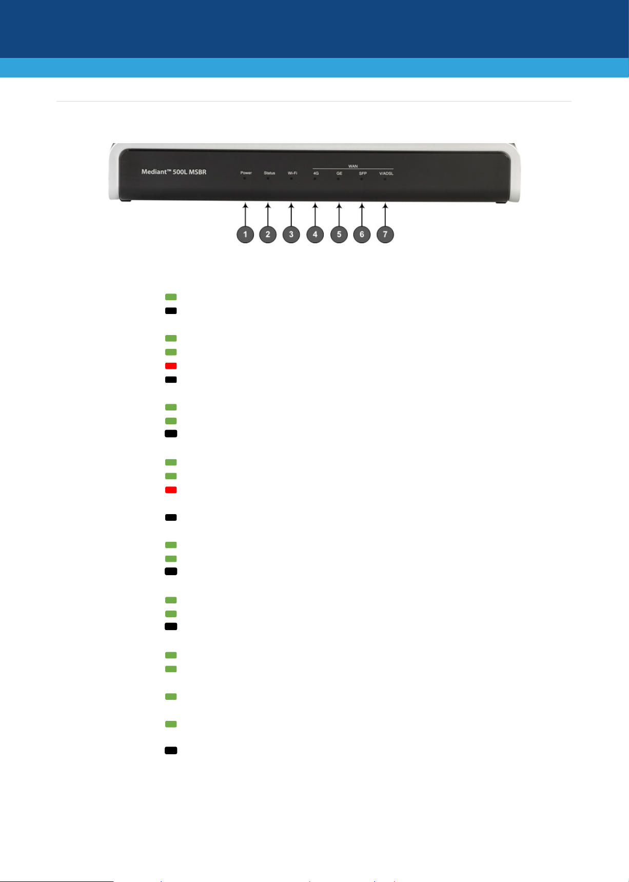
1
Power
LED indicating power status:
Green On
Power received by device
Off
No power
2
Status
LED indicating operating status:
Green On
Device is operational
Green Flashing
Initial rebooting stage or software upgrade in process
Red On
Boot failure
Off
Advanced rebooting stage
3
Wi-Fi
LED indicating Wi-Fi status:
Green On
Wi-Fi is activated.
Green Flashing
Traffic on the wireless LAN.
Off
Wi-Fi is not configured.
4
WAN 4G
LED indicating 4G cellular WAN status
Green On
Connected to cellular network.
Green Flashing
Connecting to cellular network.
Red On
No SIM card in SIM slot, or if there is a SIM card, the
device cannot connect to the cellular network
Off
Cellular interface is not configured (or not licensed)
5
WAN 4G
LED indicating Gigabit Ethernet copper WAN status
Green On
WAN GE link established.
Green Flashing
Data received or transmitted.
Off
No WAN GE link.
6
WAN SPF
LED indicating optical fiber WAN link status:
Green On
WAN fiber link established.
Green Flashing
Data received or transmitted.
Off
No WAN fiber link.
7
WAN A/VDSL
LED indicating DSL WAN link status:
Green On
DSL link connected (trained) with peer ("showtime").
Green Fast-Flashing
Training up (connection in progress) and negotiating with
peer.
Green Slow Flashing
DSL port administratively up, but idle (not connected and
no peer detected).
Green Two Fast-Flashes
and then Idle Sequences
DSL port initializing itself after being enabled or upon
mode change.
Off
DSL port administratively shutdown or not configured
Physical Description of Front Panel
[Note: Availability of certain LEDs depends on the ordered interface.]
2 | Page
Page 3

1
POWER
DC power plug entry for external AC/DC power adapter
2
ON / OFF
Power button to switch on (pressed in) and off (pressed out) the device.
3
CONSOLE
RS-232 serial interface port (RJ-45).
4 USB port, which can be used for storage on an external USB hard drive, or for 3G
cellular WAN modem for primary or backup WAN
5
//
Reset pinhole button for resetting the device or restoring it to factory defaults. To
and hold down the button for at least 12 seconds (but no more than 25 seconds).
6
S0 / WAN
WAN interface ports (e.g., copper, DSL or fiber optic), which depend on ordered
interfaces.
7
S1 / GE LAN
Up to four Gigabit Ethernet (10/100/1000Base-T) ports (RJ-45) for connecting IP
crossover cable detection.
Green On
Ethernet link established
Green Flashing
Data is received or transmitted
Off
No Ethernet link
8 Wi-Fi pinhole button for enabling or disabling Wi-Fi. Use a paper clip or any other
similar pointed object to press the button.
9
S2 / FXS,
FXO, BRI
Telephony interfaces (RJ-11 ports for FXS and FXO; RJ-45ports for ISDN BRI).
10
-
Cellular antennas for 4G LTE network.
11
SIM card slot for 4G LTE cellular.
12
-
Multiple-input and multiple-output (MIMO) 2Tx/2Rx antennas, operating in 2.4 GHz
frequency range for wireless LAN 802.11n/b/g (Wi-Fi) access point.
Physical Description of Rear Panel
[Note: The number and type of port interfaces depend on the ordered hardware configuration.]
restore to factory defaults: with a paper clip or any other similar pointed object, press
phones, computers, or switches. The ports support 1+1 Ethernet port redundancy
(active-standby), half- and full-duplex modes, auto-negotiation, and straight-through or
3 | Page
Page 4

Mounting the Device
You can mount the device in several ways:
Placing it on a desktop using the four anti-slide bumpers (supplied), which you need to stick on the
grooves located on the underside of the device.
Mounting it in a standard 19-inch rack by placing it on AudioCodes 1U 19-inch rack mount shelf
(separate orderable item). The procedure includes attaching the shelf to the rack's front posts, and
then placing the device on the shelf where it is securely held in position by the device's anti-slide
bumpers which fit into the shelf's four square-openings.
Mounting it on a wall, using the integral mounting keyholes located on its underside.
For detailed instructions on chassis mounting, refer to the Hardware Manual.
4 | Page
Page 5

Cabling the Device
Cabling depends on your ordered hardware interfaces, for example, the type of WAN interface.
1. (Only if ordered with LTE cellular) Insert the SIM card (supplied by your service provider) into the SIM
slot.
2. Connect the device's WAN port interface to the WAN.
3. Connect the yellow Gigabit Ethernet ports (labeled GE LAN) to your LAN, using an RJ-45 CAT-5 Ethernet
cable.
4. (Only If ordered with BRI interfaces) Connect the BRI ports (labeled BRI) to your ISDN BRI phones,
ISDN PBX, or ISDN network PBX, using an RJ-48 connector.
5. (Only if ordered with FXS interfaces) Connect the FXS ports (labeled FXS) to your analog telephones or
fax machines.
6. Insert the DC plug that is located at the end of the power cord of the supplied power adapter into the
device's power socket located on the rear panel and labeled POWER. Plug the power adapter directly
into a standard electrical wall outlet. Switch on the device by pressing-in the power button located on
the rear panel. When the device receives power, the Power LED turns on (green).
5 | Page
Page 6

International Headquarters
AudioCodes Inc.
Safety Precautions
This device is an indoor unit and therefore, must not be installed outdoors.
Ethernet cabling must be routed only indoors and must not exit the building.
The device must be installed and serviced only by qualified service personnel.
Do not open or dismantle the device.
Do not expose the device to water or moisture.
Make sure the device is installed in a well-ventilated location to avoid over heating of internal
components and subsequent damage.
Do not place any object on top of the device and make sure that sufficient clearance from the top and
sides are maintained to ensure proper airflow to avoid over heating of internal components.
Operate the device in an ambient temperature (Tma) that does not exceed 40°C (104°F).
The device must be installed only in restricted access locations.
Use only the supplied AC/DC power adapter for connection to the power source.
In case of a malfunction, do not attempt to fix the power adapter and do not use any other type of
power adapter. Contact AudioCodes for further assistance.
Operate the device only from the type of power source indicated on the chassis.
Installation of the device must be in accordance with national electrical codes and conform to local
regulations.
Use minimum 26-AWG wiring for FXO ports.
©2020 AudioCodes Ltd. All rights reserved. AudioCodes, AC, HD VoIP, HD VoIP Sounds Better, IPmedia, Mediant,
MediaPack, What’s Inside Matters, OSN, SmartTAP, User Management Pack, VMAS, VoIPerfect, VoIPerfectHD, Your
Gateway To VoIP, 3GX, VocaNom, AudioCodes One Voice, AudioCodes Meeting Insights, AudioCodes Room Experience
and CloudBond are trademarks or registered trademarks of AudioCodes Limited. All other products or trademarks are
property of their respective owners. Product specifications are subject to change without notice.
1 Hayarden Street,
Airport City
Lod 7019900, Israel
Tel: +972-3-976-4000
Fax: +972-3-976-4040
Contact us: https://www.audiocodes.com/corporate/offices-worldwide
Website: https://www.audiocodes.com/
200 Cottontail Lane,
Suite A101E,
Somerset, NJ 08873
Tel: +1-732-469-0880
Fax: +1-732-469-2298
Document #: LTRT-10509
Date Published: 11/08/2020
6 | Page
 Loading...