


QUALITY, RLIABILITY, & PURE BLISS
ACIS MATCHED COMPONENT SYSTEM
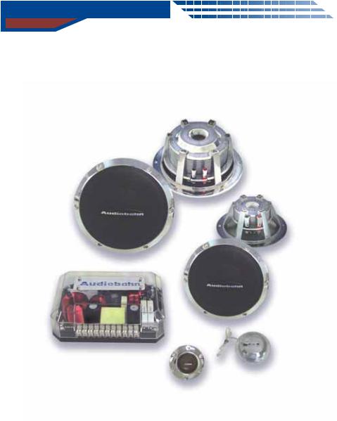
ACIS52 / ACIS62 / ACIS63
OPERATING INTSTRUCTIONS
PLEASE RETAIN MANUAL FOR FUTRE USE AND REFERENCE
Deprive yourself no further...
View our complete line of product at...
www .audiobahninc.com

Introduction
TABLE OF CONTENTS
1.Introduction..................................................................
2.Features and Specifications...........................................
3.Wiring and X-Over Design..............................................
4.Frequency Respanse.....................................................
5.Mounting and Installation...............................................
6.Choosing a Location......................................................
7.Trouble Shooting...........................................................
8.Warning/Disclaimer.......................................................
9.Warranty.......................................................................
Introduction
Thank you for purchasing an Audiobahn Matched Component Speaker System, specifically designed for the mobile environment. This manual contains important information about hook-up and set-up procedures and integrating this unit into your car stereo system. With propercare and Installation, this Matched Component Speaker System will provide you with many years of high performance listening enjoyment.
Before making any electrical connections, make sure that you disconnect the battery's ground cable to prevent the possibility ofshort circuits or damage to your electronic equipment.(if your stereo has an Anti-theft code DO NOT disconnect the battery.)
1

Features and specifications
FEATURES
WOOFER
Custo |
Tool Cast Alu |
inu Basket |
Chro |
e Plated Magnetic Plates |
|
High Grade Strontiu |
Ring Magnet |
|
Gray Polyurethane Half Roll Rubber Edge |
||
Gray |
oven Glass Fiber Cone |
|
2 Layer CCA 4 Oh |
Voice Coil |
|
High-Te p Coating Glass Fiber For er Copper Faraday Ring In Motor Design
MID-RANGE
Custo |
|
Tool Cast Alu |
inu Basket |
Chro |
e Plated Magnetic Plates |
||
High Te |
p Neody iu |
Ring Magnet |
|
Custo |
|
Gray Polyurathane/Foa Flat Edge |
|
Gray |
oven Glass Fiber Cone |
||
2 Layer CCA 4 Oh |
Voice Coil |
||
High-Te |
p Coating Glass Fiber For er |
||
Copper Faraday Cap In Motor Design
SPECIFICATIONS
POWER HANDLING
ACIS-52: 160 RMS
ACIS-62: 200 RMS
ACIS-63: 320 RMS
FREQUENCY
ACIS-52: 35Hz - 35kHz
ACIS-62: 30Hz - 35kHz
ACIS-63: 30Hz - 35kHz
TWEETER
Custo |
Tool Cast Alu |
inu |
Mounting Plate |
|
High Te |
p Neody iu |
Ring Magnet |
||
Ferro Fluid Used For Da pening Resonance |
||||
FEA Reverse Polyurethane Edge |
|
|||
Custo |
FEA 1" Concave Alu |
inu |
Do e |
|
2 Layer CCA 4 Oh |
Voice Coil |
|
||
High-Te |
p Coating Glass Fiber For |
er |
||
Copper Faraday Cap In Motor Design |
||||
CROSSOVER
Custo |
Tool Clear InjectionMolded Casing |
12V / Re |
ote Input Design For LED Illu ination |
Heavy Gauge Ter inalFor High Power Input |
|
EQ Circuit Design For Resonance Da pening
L-Pad CircuitDesign To AttenuateLoud Drivers Precise FilterDesign To Control Sound Overlap MultipleFuse Design To ProtectAll Co ponent Co plete iring and Mounting Hardware
SENSITIVITY
ACIS-52: 90dB +/-3dB
ACIS-62: 91dB +/-3dB
ACIS-63: 91dB +/-2dB
FILTER RESPONSE
ACIS-52: 2000Hz - 12dB Octave ACIS-62: 2000Hz - 12dB Octave ACIS-63: 350Hz & 4.5KHz - 12dB Octave
2
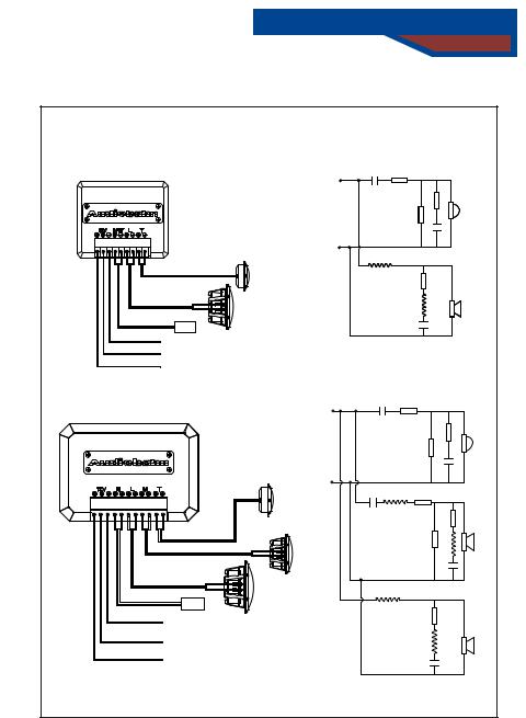
 Wiring and X-over Design
|
ASSEMBLY MANUAL |
|
|
|
|
|
ACIS-52 |
|
|
|
|
Crossover |
ACIS-62 |
C1 |
R1 |
|
|
|
|
|
|
R3 |
|
|
|
|
|
R2 |
|
|
|
|
|
C2 |
|
|
|
L1 |
|
|
|
|
Tweeter |
|
|
R4 |
|
|
|
|
|
|
|
|
Woofer |
|
|
L2 |
|
|
|
|
|
|
|
|
AMP |
|
|
C3 |
|
|
|
|
|
|
|
|
-12V |
|
|
|
|
|
Remote |
|
|
|
|
|
+12V |
|
|
|
|
|
ACIS-63 |
C1 |
|
R1 |
|
|
|
|
|
||
Crossover |
|
|
|
|
|
|
|
|
|
|
R3 |
|
|
|
|
R2 |
|
|
|
|
|
|
C2 |
|
Tweeter |
C3 |
L1 |
R4 |
|
|
|
|
|
|
|
|
|
|
|
|
R5 |
|
Mid-range |
|
|
|
|
|
|
|
|
R6 |
L2 |
|
|
|
|
|
C4 |
|
Woofer |
L3 |
|
|
|
|
|
|
|
|
|
|
AMP |
|
|
|
|
|
- 12V |
|
|
R4 |
|
|
|
|
|
|
|
|
Remote |
|
|
L4 |
|
|
+12V |
|
|
C5 |
|
|
|
|
|
|
 Loading...