

Page 1
AUDIO FUTURA
AUDIO FUTURA
AUDIO FUTURAAUDIO FUTURA
spa
Rossini CD Player
REV 2.0
Issue Date: June 2008
AUDIO FUTURA
Research & Development
E-Mail (support):
sblanda@audioanalogue.com
podesta@audioanalogue.com
saggini@audioanlogue.com
elia@audioanalogue.com
spa
Rossini CD Player REV 2.0 1 / 7
Page 2
AUDIO FUTURA
AUDIO FUTURA
AUDIO FUTURAAUDIO FUTURA
spa
Introduction
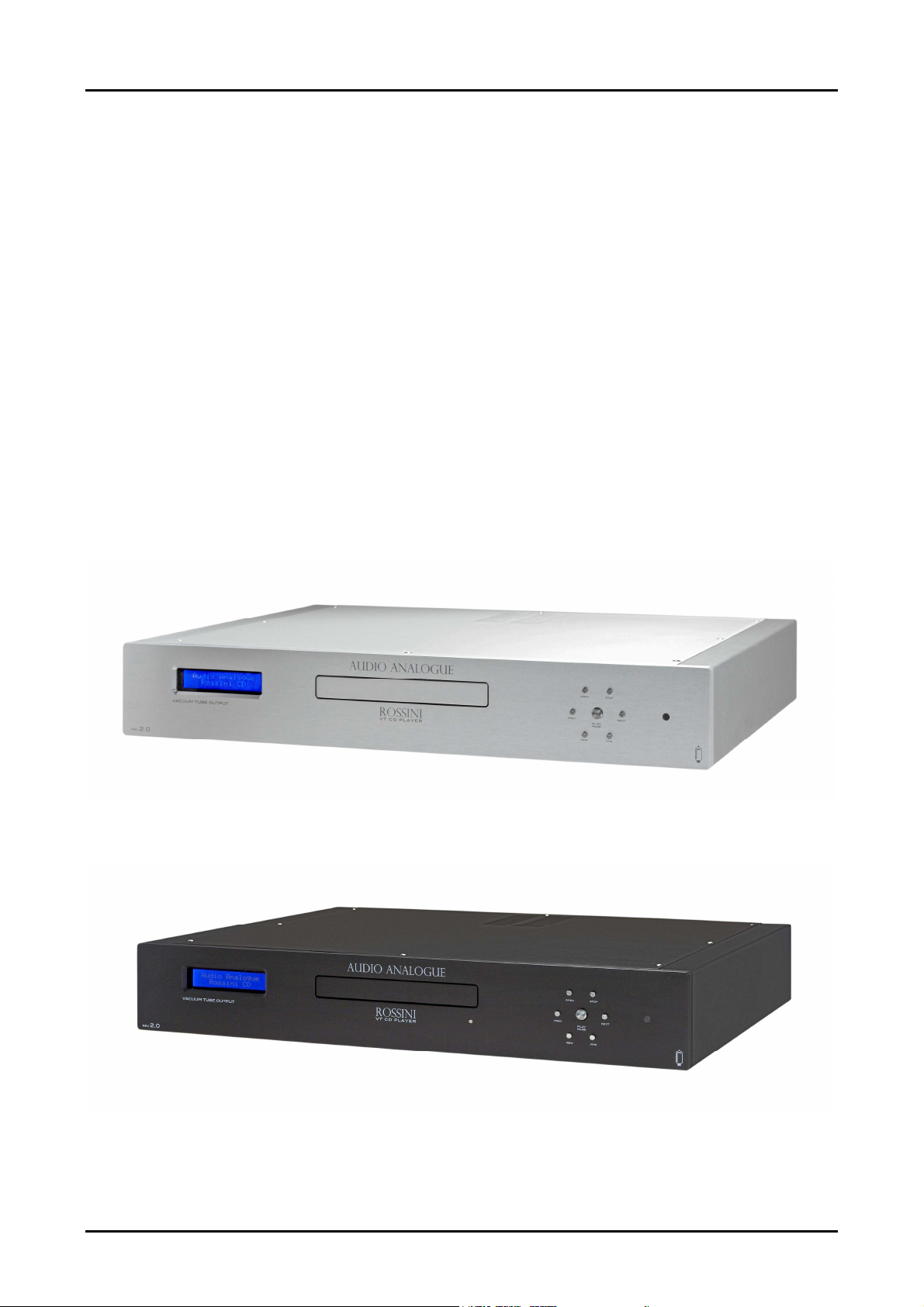
Even if the Rossini CD Player REV2.0 has the same look of the previous revision it is
completely different inside. With the REV2.0 we have created a unit where the
vacuum tube technologies and the best digital technologies could be perfectly mixed
together. The circuits we have used come from a long research expecially for the
original vacuum tube output stage that is the strong point of this CD Player. The
results we have had have been ever higher then the target we would reach. In
particular the listening sessions shows that the Rossini CD Player REV2.0 has a
“different “ and “original” sound compared to other CD Players.
The Rossini CD Player REV2.0 is a starting point because it demonstrates that the
vacuum tube and newest technologies union has to be developed. We must run new
streets, try new circuital solutions, go over the old configurations without falling in the
mistake of a “too much microelectronic” approach.
Rossini CD Player REV 2.0 2 / 7
Page 3
AUDIO FUTURA
AUDIO FUTURA
AUDIO FUTURAAUDIO FUTURA
spa
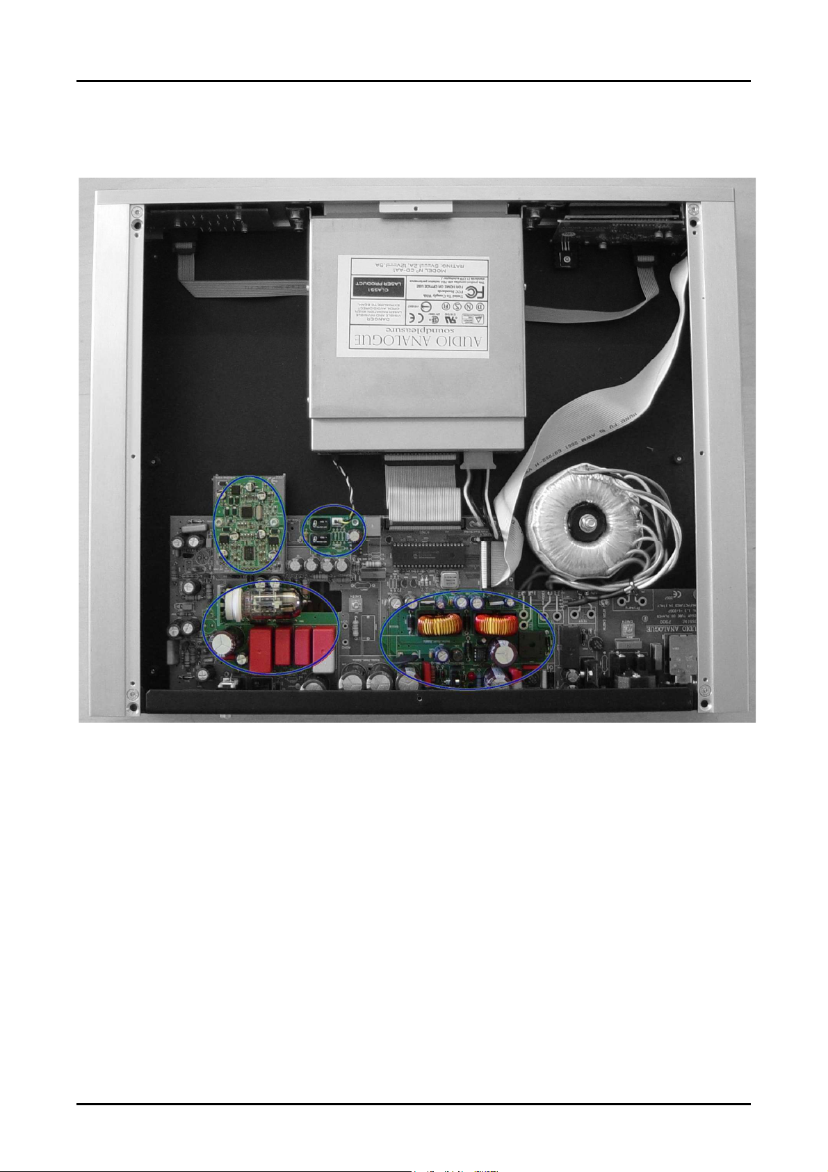
Unit description
2
2
2
3
3
3
1. Digital Input
2. Digital Analog Conversion Section
3. Output Stage
4. Anodic Power supply
1
1
1
4
4
4
Rossini CD Player REV 2.0 3 / 7
Page 4

AUDIO FUTURA
AUDIO FUTURA
AUDIO FUTURAAUDIO FUTURA
1. Digital Input
“Jitterless” and sturdy. To avoid any interference from ground returns we have
isolated the S/PDIF CD mechanism output from the main board by a transformer. The
SPDIF signal is then send to the DA conversion PCB.
2. Digital Analog Conversion Section
The circuits performing
the digital to analog
conversion are placed on
a board physically
separated from the main
board. That’s to avoid any
interference on the analog
signals due to the return
currents of the digital
parts of the DAC and
transceiver.
On the board there are:
the transceiver, the DAC
and all their frameworks
including their power
supply voltage regulators
and capacitors. The
voltage for the “DAC
board” is obtained by a
dedicated secondary of the transformer and a dedicated voltage regulator. The
regulated voltage is then filtered by a RC filter. Then that voltage is used to produce
the voltages for the transceiver and DAC by two voltage regulators. The components
on the “DAC board “ are predominantly SMD reducing the length of traces carrying
high frequency signals to avoid irradiation effects. From the “conversion board” the
voltage DAC output is sent to the main board.
Rossini CD Player REV 2.0 4 / 7
spa
The S/PDIF signal is taken
from the Cd Mechanism.
We have used a CD ROM
mechanism specifically
developed for the audio
application (We even
contributed to the design
for the firmware test part
and for the mechanical
stability tests). In fact the
maximum speed has been
reduced compared to the
standard CD ROM
mechanisms, and the
reading procedure has
been made more
Page 5

AUDIO FUTURA
AUDIO FUTURA
AUDIO FUTURAAUDIO FUTURA
3. Output Stage
but on the base of listening tests too. What we have tried to do is a balance of the
vacuum tube “coloring” and DAC “cleanliness”.
The output stage’s gain is such that we have 1.9Vrms output for a 0dBV track.
4. Anodic Power supply
The output stage used is
not based on a differential
input so the noise on the
anodic supply is not
reduced by the circuit.
That’s why we have
worked on the anodic
power supply to make it
as clean as possible. The
voltage for the anodic
power supply is obtained
by a high voltage
dedicated secondary and
then regulated with a
discrete components
voltage regulator. The
regulator output is then filtered by a RC filter with a very low time constant (less then
1.24).
All the components used are high quality and low tolerance. The Board that is often a
neglected “componet” has been designed in respect of all noise reduction techniques
expecially for the current return parts and power supply traces.
Rossini CD Player REV 2.0 5 / 7
spa
The output stage is an
original circuit designed
by the Audio Analogue
R&D office to emphisize
the sound propertyes of
the vacuum tube and to
take vantage of the solid
state technology. It is an
inedited DC coupled low
feedback three stage
structure where the
vacuum tube is the first
one. The amount of
feedback has been
choosen not only on the
base of measurements
Page 6

AUDIO FUTURA
AUDIO FUTURA
AUDIO FUTURAAUDIO FUTURA
spa
Measurements
As first I want to point out that the frequency axis scale in the following graphics is
logharitmic. In such way is possible to see the low frequency noise due to the power
supply. Often the related measurements have a linear frequency axis scale. In such
way the low frequency part of the spectrum is not visible. Perhaps this is expressly
done to not show low frequency noise. Anyway the 50Hz noise component due to the
AC Power supply and the 100Hz component due to the effect of the rectification of the
AC power supply are the cause of the loudspeaker “hum”. That’s why they must be
reduced in every audio devices.
Note: All the measurements performed with a Audio Precision System Two Cascade.
Misura dello spettro con apparecchio in stop.
Rossini CD Player REV 2.0 6 / 7
Page 7

AUDIO FUTURA
AUDIO FUTURA
AUDIO FUTURAAUDIO FUTURA
spa
Misura dello spettro per 1Khz 0dbv
Misura dello spettro per 1 KHz -10dbv.
Rossini CD Player REV 2.0 7 / 7
 Loading...