

Page 1
Protected by copyright. Copying for private or commercial purposes, in part or in whole, is not
permitted unless authorised by AUDI AG. AUDI AG does not guarantee or accept any liability
with respect to the correctness of information in this document. Copyright by AUDI AG.
Service
Workshop Manual
Audi 100 1991 ➤ , Audi 80 1992 ➤ ,
Audi A1 2011 ➤ , Audi A2 2001 ➤ ,
Audi A3 1997 ➤ , Audi A3 2004 ➤ ,
Audi A4 1995 ➤ , Audi A4 2001 ➤ ,
Audi A4 2008 ➤ ,
Audi A4 Cabriolet 2003 ➤ ,
Audi A5 Cabriolet 2009 ➤ ,
Audi A5 Coupé 2008 ➤ ,
Audi A5 Sportback 2010 ➤ ,
Audi A6 1995 ➤ , Audi A6 1998 ➤ ,
Audi A6 2005 ➤ ,
Audi A7 Sportback 2011 ➤ ,
Audi A8 1994 ➤ , Audi A8 2003 ➤ ,
Audi A8 2010 ➤ , Audi Cabriolet 1991 ➤ ,
Audi Q5 2008 ➤ , Audi Q7 2007 ➤ ,
Audi R8 2007 ➤ , Audi TT 1999 ➤ ,
Audi TT 2007 ➤
Air conditioner with refrigerant R134a
Edition 06.2010
Service Department. Technical Information
Page 2
Protected by copyright. Copying for private or commercial purposes, in part or in whole, is not
permitted unless authorised by AUDI AG. AUDI AG does not guarantee or accept any liability
with respect to the correctness of information in this document. Copyright by AUDI AG.
Service
List of Workshop Manual Repair GroupsList of Workshop Manual
Repair GroupsList of Workshop Manual Repair Groups
Re pa ir G ro up
87 - Air conditioning system
Technical information should always be available to the foremen and mechanics, because their
careful and constant adherence to the instructions is essential to ensure vehicle road-worthiness and
safety. In addition, the normal basic safety precautions for working on motor vehicles must, as a
matter of course, be observed.
All rights reserved.
No reproduction without prior agreement from publisher.
Copyright © 2010 Audi AG, Ingolstadt A0053300220
Page 3
Protected by copyright. Copying for private or commercial purposes, in part or in whole, is not
permitted unless authorised by AUDI AG. AUDI AG does not guarantee or accept any liability
with respect to the correctness of information in this document. Copyright by AUDI AG.
Audi 100 1991 ➤ , Audi 80 1992 ➤ , Audi A1 2011 ➤ , Audi A2 2001 ➤ , A ...
Air conditioner with refrigerant R134a - Edition 06.2010
Contents
87 - Air conditioning system . . . . . . . . . . . . . . . . . . . . . . . . . . . . . . . . . . . . . . . . . . . . 1
1 General information on air conditioning systems . . . . . . . . . . . . . . . . . . . . . . . . . . . . . . . . 1
1.1 Introduction . . . . . . . . . . . . . . . . . . . . . . . . . . . . . . . . . . . . . . . . . . . . . . . . . . . . . . . . . . . . . . 1
1.2 Other reference material . . . . . . . . . . . . . . . . . . . . . . . . . . . . . . . . . . . . . . . . . . . . . . . . . . 1
1.3 Principles of air conditioning systems . . . . . . . . . . . . . . . . . . . . . . . . . . . . . . . . . . . . . . . . 2
1.4 Refrigerant R134a . . . . . . . . . . . . . . . . . . . . . . . . . . . . . . . . . . . . . . . . . . . . . . . . . . . . . . . . 4
1.5 Properties of refrigerant R134a . . . . . . . . . . . . . . . . . . . . . . . . . . . . . . . . . . . . . . . . . . . . . . 5
1.6 Refrigerant oil . . . . . . . . . . . . . . . . . . . . . . . . . . . . . . . . . . . . . . . . . . . . . . . . . . . . . . . . . . . . 7
1.7 How air conditioning works . . . . . . . . . . . . . . . . . . . . . . . . . . . . . . . . . . . . . . . . . . . . . . . . . . 8
1.8 General work safety . . . . . . . . . . . . . . . . . . . . . . . . . . . . . . . . . . . . . . . . . . . . . . . . . . . . . . 10
1.9 Product properties . . . . . . . . . . . . . . . . . . . . . . . . . . . . . . . . . . . . . . . . . . . . . . . . . . . . . . . . 10
1.10 Handling refrigerant . . . . . . . . . . . . . . . . . . . . . . . . . . . . . . . . . . . . . . . . . . . . . . . . . . . . . . 10
1.11 Handling pressure vessels . . . . . . . . . . . . . . . . . . . . . . . . . . . . . . . . . . . . . . . . . . . . . . . . . . 11
1.12 Safety regulations for working with extraction and charging systems . . . . . . . . . . . . . . . . 12
1.13 Safety measures for working on vehicles with air conditioning system and for handling
refrigerant R134a . . . . . . . . . . . . . . . . . . . . . . . . . . . . . . . . . . . . . . . . . . . . . . . . . . . . . . . . 13
1.14 Basic rules for working on refrigerant circuit . . . . . . . . . . . . . . . . . . . . . . . . . . . . . . . . . . . . 14
1.15 Before using air conditioner after system has been re-charged . . . . . . . . . . . . . . . . . . . . . . 15
2 General information on refrigerant circuit . . . . . . . . . . . . . . . . . . . . . . . . . . . . . . . . . . . . . . 16
2.1 Components of refrigerant circuit . . . . . . . . . . . . . . . . . . . . . . . . . . . . . . . . . . . . . . . . . . . . 16
2.2 Arrangement of the refrigerant circuit components and their influence on the high and low-
pressure ends . . . . . . . . . . . . . . . . . . . . . . . . . . . . . . . . . . . . . . . . . . . . . . . . . . . . . . . . . . 16
2.3 Design of refrigerant circuit . . . . . . . . . . . . . . . . . . . . . . . . . . . . . . . . . . . . . . . . . . . . . . . . 25
2.4 Connections for quick-release coupling in refrigerant circuit . . . . . . . . . . . . . . . . . . . . . . . . 26
2.5 Switches and senders in refrigerant circuit and related connections . . . . . . . . . . . . . . . . 28
2.6 Electrical components not installed in refrigerant circuit . . . . . . . . . . . . . . . . . . . . . . . . . . 32
2.7 Pressures and temperatures in refrigerant circuit . . . . . . . . . . . . . . . . . . . . . . . . . . . . . . . . 33
2.8 Test and measurement operations which can be performed with a pressure gauge . . . . 37
2.9 Air conditioner service and recycling units . . . . . . . . . . . . . . . . . . . . . . . . . . . . . . . . . . . . . . 38
2.10 Repair notes for refrigerant circuit . . . . . . . . . . . . . . . . . . . . . . . . . . . . . . . . . . . . . . . . . . . . 39
3 Laws and regulations . . . . . . . . . . . . . . . . . . . . . . . . . . . . . . . . . . . . . . . . . . . . . . . . . . . . . . 40
3.1 Laws and regulations . . . . . . . . . . . . . . . . . . . . . . . . . . . . . . . . . . . . . . . . . . . . . . . . . . . . . . 40
4 Refrigerant circuit . . . . . . . . . . . . . . . . . . . . . . . . . . . . . . . . . . . . . . . . . . . . . . . . . . . . . . . . 45
4.1 Important repair notes for air conditioning systems . . . . . . . . . . . . . . . . . . . . . . . . . . . . . . 45
4.2 Converting refrigerant circuits from refrigerant R12 to refrigerant R134a . . . . . . . . . . . . . . 45
4.3 Working with the air conditioner service station . . . . . . . . . . . . . . . . . . . . . . . . . . . . . . . . . . 46
4.4 Blowing out refrigerant circuit with compressed air and nitrogen . . . . . . . . . . . . . . . . . . . . 55
4.5 Flushing (cleaning) refrigerant circuit with refrigerant R134a . . . . . . . . . . . . . . . . . . . . . . . . 59
4.6 Tracing leaks in refrigerant circuit . . . . . . . . . . . . . . . . . . . . . . . . . . . . . . . . . . . . . . . . . . . . 87
5 Problems with refrigerant circuit . . . . . . . . . . . . . . . . . . . . . . . . . . . . . . . . . . . . . . . . . . . . . . 97
5.1 Possible complaints about refrigerant circuit . . . . . . . . . . . . . . . . . . . . . . . . . . . . . . . . . . . . 97
6 Connecting air conditioner service station . . . . . . . . . . . . . . . . . . . . . . . . . . . . . . . . . . . . . . 99
6.1 Connecting air conditioner service station on vehicles with a connection on the low and high-
pressure end of the refrigerant circuit . . . . . . . . . . . . . . . . . . . . . . . . . . . . . . . . . . . . . . . . . . 99
6.2 Connecting air conditioner service station on vehicles with no connection on the low-pressure
end of the refrigerant circuit . . . . . . . . . . . . . . . . . . . . . . . . . . . . . . . . . . . . . . . . . . . . . . . . 99
7 Checking pressures . . . . . . . . . . . . . . . . . . . . . . . . . . . . . . . . . . . . . . . . . . . . . . . . . . . . . . 103
7.1 Checking pressures in refrigerant circuit with air conditioner service station (with ignition
switched off) . . . . . . . . . . . . . . . . . . . . . . . . . . . . . . . . . . . . . . . . . . . . . . . . . . . . . . . . . . . . 103
7.2 Checking pressures on vehicles with a restrictor and reservoir (with internally regulated air
conditioner compressor) . . . . . . . . . . . . . . . . . . . . . . . . . . . . . . . . . . . . . . . . . . . . . . . . . . 108
7.3 Checking pressures on vehicles with an expansion valve and receiver (with internally
regulated air conditioner compressor) . . . . . . . . . . . . . . . . . . . . . . . . . . . . . . . . . . . . . . . . 113
Contents i
Page 4
Protected by copyright. Copying for private or commercial purposes, in part or in whole, is not
permitted unless authorised by AUDI AG. AUDI AG does not guarantee or accept any liability
with respect to the correctness of information in this document. Copyright by AUDI AG.
Audi 100 1991 ➤ , Audi 80 1992 ➤ , Audi A1 2011 ➤ , Audi A2 2001 ➤ , A ...
Air conditioner with refrigerant R134a - Edition 06.2010
7.4 Checking pressures on vehicles with restrictor, reservoir and air conditioner compressor
regulating valve N280 (with externally regulated air conditioner compressor) . . . . . . . . . . 118
7.5 Checking pressures on vehicles with expansion valve, receiver and air conditioner
compressor regulating valve N280 (with externally regulated air conditioner compressor)
. . . . . . . . . . . . . . . . . . . . . . . . . . . . . . . . . . . . . . . . . . . . . . . . . . . . . . . . . . . . . . . . . . . . . . . . 126
8 Renewing components of refrigerant circuit . . . . . . . . . . . . . . . . . . . . . . . . . . . . . . . . . . . . 136
8.1 Renewing components . . . . . . . . . . . . . . . . . . . . . . . . . . . . . . . . . . . . . . . . . . . . . . . . . . . . 136
9 Capacities for refrigerant R134a, refrigerant oil and approved refrigerant oils . . . . . . . . . . 144
9.1 Capacities for refrigerant R134a . . . . . . . . . . . . . . . . . . . . . . . . . . . . . . . . . . . . . . . . . . . . 144
9.2 Approved refrigerant oils and refrigerant oil capacities . . . . . . . . . . . . . . . . . . . . . . . . . . . . 164
10 Test equipment and tools . . . . . . . . . . . . . . . . . . . . . . . . . . . . . . . . . . . . . . . . . . . . . . . . . . 189
10.1 List of testers, tools and materials . . . . . . . . . . . . . . . . . . . . . . . . . . . . . . . . . . . . . . . . . . . . 189
10.2 Tools and materials available from regional sales centre or importer . . . . . . . . . . . . . . . . 191
10.3 Commercially available tools and materials . . . . . . . . . . . . . . . . . . . . . . . . . . . . . . . . . . . . 194
10.4 Improvised tools . . . . . . . . . . . . . . . . . . . . . . . . . . . . . . . . . . . . . . . . . . . . . . . . . . . . . . . . . . 195
ii Contents
Page 5

Protected by copyright. Copying for private or commercial purposes, in part or in whole, is not
permitted unless authorised by AUDI AG. AUDI AG does not guarantee or accept any liability
with respect to the correctness of information in this document. Copyright by AUDI AG.
Audi 100 1991 ➤ , Audi 80 1992 ➤ , Audi A1 2011 ➤ , Audi A2 2001 ➤ , A ...
Air conditioner with refrigerant R134a - Edition 06.2010
87 – Air conditioning system
1 General information on air condition‐
ing systems
♦ Introduction ⇒ page 1
♦ Other reference material ⇒ page 1
♦ Principles of air conditioning systems ⇒ page 2
♦ Refrigerant R134a ⇒ page 4
♦ Properties of refrigerant R134a ⇒ page 5
♦ Refrigerant oil ⇒ page 7
♦ How air conditioning works ⇒ page 8
♦ General work safety ⇒ page 10
♦ Product properties ⇒ page 10
♦ Handling refrigerant ⇒ page 10
♦ Handling pressure vessels ⇒ page 11
♦ Safety regulations for working with extraction and charging
systems ⇒ page 12
♦ Safety measures for working on vehicles with air conditioning
system and for handling refrigerant R134a ⇒ page 13
♦ Basic rules for working on refrigerant circuit ⇒ page 14
♦ Before using air conditioner after system has been re-charged
⇒ page 15
1.1 Introduction
This manual is intended to provide foremen and mechanics with
the basic knowledge needed to ensure reliable and successful
repairs.
Note
This requires careful study of the manual, coupled with suitable
training on automotive air conditioning systems (with a qualifica‐
tion test if applicable) and the ability to apply the acquired exper‐
tise in practice.
This document is a compact reference work which should be kept
at the workplace. It should also be available for presentation to
the responsible supervisory agency on request.
1.2 Other reference material
♦ Workshop manual for model-specific servicing work ⇒ Heat‐
ing, air conditioning; Rep. gr. 87 or ⇒ Air conditioning; Rep.
gr. 87 (vehicle-specific workshop manual) and ⇒ Current flow
diagrams, Electrical fault finding and Fitting locations
♦ Technical Service Handbook (TPI) outlining action to be taken
to rectify current problems
♦ Self-study programmes, e.g. ⇒ Self-study programme No.
208 ; Air conditioning systems in motor vehicles
♦ Video training courses for dealerships
1. General information on air conditioning systems 1
Page 6
Protected by copyright. Copying for private or commercial purposes, in part or in whole, is not
permitted unless authorised by AUDI AG. AUDI AG does not guarantee or accept any liability
with respect to the correctness of information in this document. Copyright by AUDI AG.
Audi 100 1991 ➤ , Audi 80 1992 ➤ , Audi A1 2011 ➤ , Audi A2 2001 ➤ , A ...
Air conditioner with refrigerant R134a - Edition 06.2010
♦ List of special tools and workshop equipment required for
servicing air conditioning systems ⇒ Workshop equipment
catalogue
♦ Service Organisation Handbook, Vol. „1“ „Additional equip‐
ment“ ⇒ Audi ServiceNet, Handbooks
♦ Air conditioner with refrigerant R12 Workshop Manual (for ve‐
hicles manufactured up to model year 1993; this Workshop
Manual is available in hardcopy form only)
1.3 Principles of air conditioning systems
♦ Physical principles ⇒ page 2
♦ Pressure and boiling point ⇒ page 2
♦ Vapour pressure table for refrigerant R134a ⇒ page 3
♦ Properties of refrigerant R134a ⇒ page 5
1.3.1 Physical principles
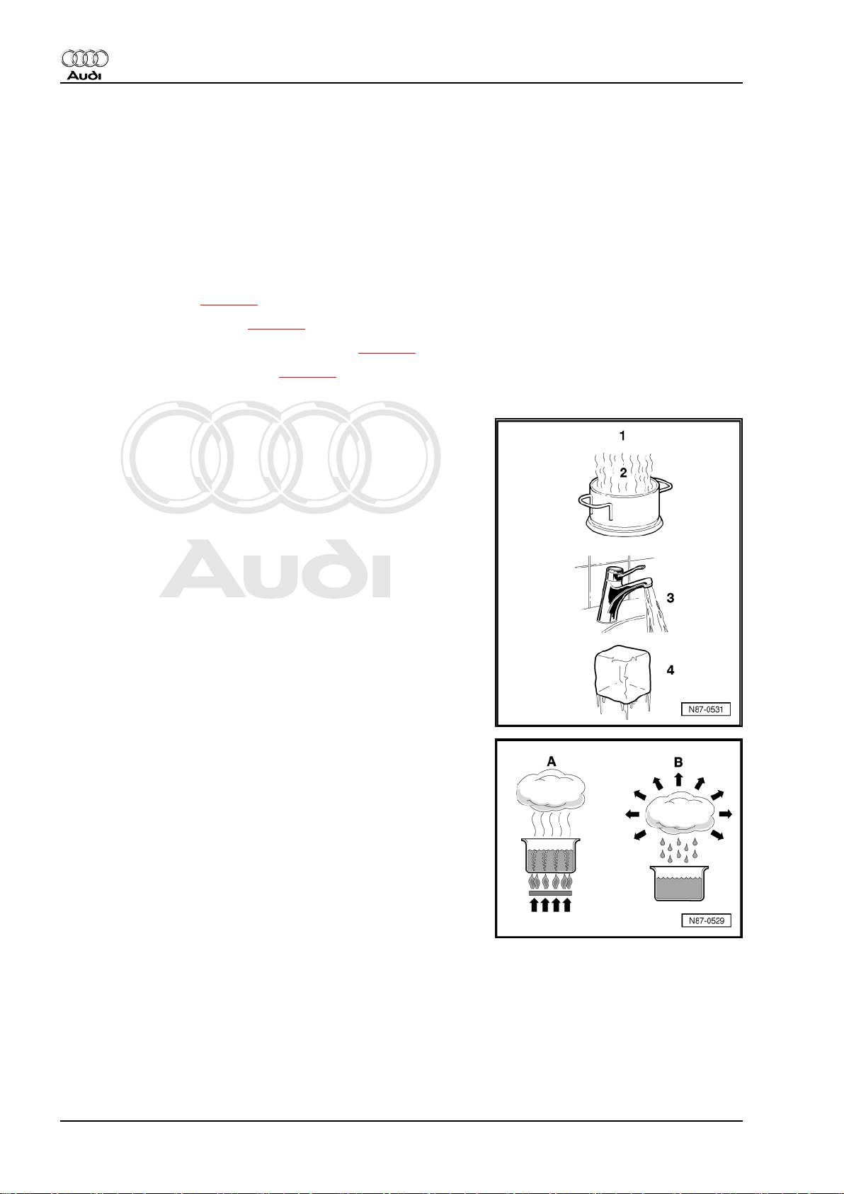
The four familiar states of water apply to air conditioning refriger‐
ants, too.
1 - Gas (invisible)
2 - Vapour
3 - Liquid
4 - Solid
When water is heated in a vessel (heat absorption), water vapour
can be seen to rise. If the vapour is further heated through heat
absorption, the visible vapour turns into invisible gas. The process
is reversible. If heat is extracted from gaseous water -A-, it
changes first to vapour -B-, then to water and finally to ice.
A - Heat absorption
B - Heat emission
Heat always flows from a warmer to a colder substance
Every substance consists of a mass of moving molecules. The
fast moving molecules of a warmer substance give off some of
their energy to the cooler and thus slower molecules. As a result,
the molecular motion of the warmer substance slows down and
that of the colder substance is accelerated. This process contin‐
ues until the molecules of both substances are moving at the
same speed. They are then at the same temperature and no fur‐
ther heat exchange takes place.
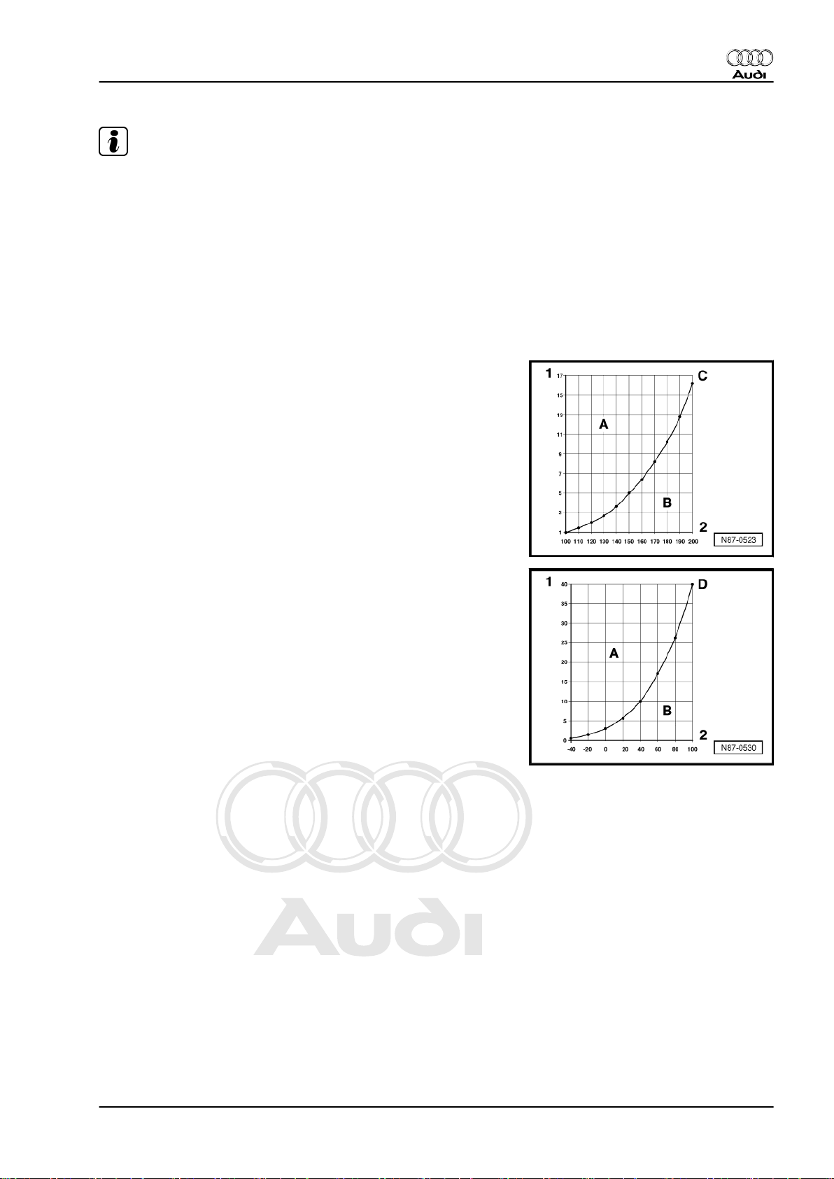
1.3.2 Pressure and boiling point
The boiling point given in tables for a liquid is always referenced
to an atmospheric pressure of 1 bar. If the pressure acting on a
liquid changes, its boiling point also changes.
2 Rep. gr.87 - Air conditioning system
Page 7
Protected by copyright. Copying for private or commercial purposes, in part or in whole, is not
permitted unless authorised by AUDI AG. AUDI AG does not guarantee or accept any liability
with respect to the correctness of information in this document. Copyright by AUDI AG.
Audi 100 1991 ➤ , Audi 80 1992 ➤ , Audi A1 2011 ➤ , Audi A2 2001 ➤ , A ...
Air conditioner with refrigerant R134a - Edition 06.2010
Note
Pressure may be given in various units: 1 MPa (megapascal) cor‐
responds to 10 bar gauge pressure or 145 psi; 1 bar absolute
pressure corresponds to 0 bar gauge pressure, which is roughly
equivalent to atmospheric pressure.
For example, the lower the pressure, the lower the temperature
at which water boils.
The vapour pressure curves for water and refrigerant R134a show
for example that, at constant pressure, reducing the temperature
changes vapour to liquid (in the condenser) or that, for instance,
reducing pressure causes the refrigerant to change from the liquid
to the vapour state (in the evaporator).
Vapour pressure curve for water
A - Liquid
B - Gaseous
C - Vapour pressure curve for water
1 - Pressure acting on liquid in bar (absolute)
2 - Temperature in °C
Vapour pressure curve for refrigerant R134a
A - Liquid
B - Gaseous
D - Vapour pressure curve for refrigerant R134a
1 - Pressure acting on liquid in bar (absolute)
2 - Temperature in °C
1.3.3 Vapour pressure table for refrigerant R134a
The vapour pressure table for every refrigerant is published in
literature for refrigeration system engineers. This table makes it
possible to determine the vapour pressure acting on the column
of liquid in a vessel if the temperature of the vessel is known.
As there is a known characteristic vapour pressure table for every
refrigerant, the type of refrigerant can be identified by way of
pressure and temperature measurement.
1. General information on air conditioning systems 3
Page 8
Protected by copyright. Copying for private or commercial purposes, in part or in whole, is not
permitted unless authorised by AUDI AG. AUDI AG does not guarantee or accept any liability
with respect to the correctness of information in this document. Copyright by AUDI AG.
Audi 100 1991 ➤ , Audi 80 1992 ➤ , Audi A1 2011 ➤ , Audi A2 2001 ➤ , A ...
Air conditioner with refrigerant R134a - Edition 06.2010
Note
♦
At absolute pressure, „0 bar“ corresponds to an absolute vac‐
uum. Normal atmospheric pressure corresponds to „1 bar“
absolute pressure. On the scales of most pressure gauges, „0
bar“ corresponds to an absolute pressure of 1 bar (this is in‐
dicated by the value „-1 bar“ below „0“).
♦
Pressure may be given in various units: 1 MPa (megapascal)
corresponds to 10 bar gauge pressure or 145 psi; 1 bar ab‐
solute pressure corresponds to 0 bar gauge pressure, which
is roughly equivalent to atmospheric pressure.
Temperature in °C Pressure in bar (gauge pres‐
sure), R134a
-45 -0,61
-40 -0,49
-35 -0,34
-30 -0,16
-25 0,06
-20 0,32
-15 0,63
-10 1,00
-5 1,43
0 1,92
5 2,49
10 3,13
15 3,90
20 4,70
25 5,63
30 6,70
35 7,83
40 9,10
45 10,54
50 12,11
55 13,83
60 15,72
65 17,79
70 20,05
75 22,52
80 25,21
85 28,14
90 31,34
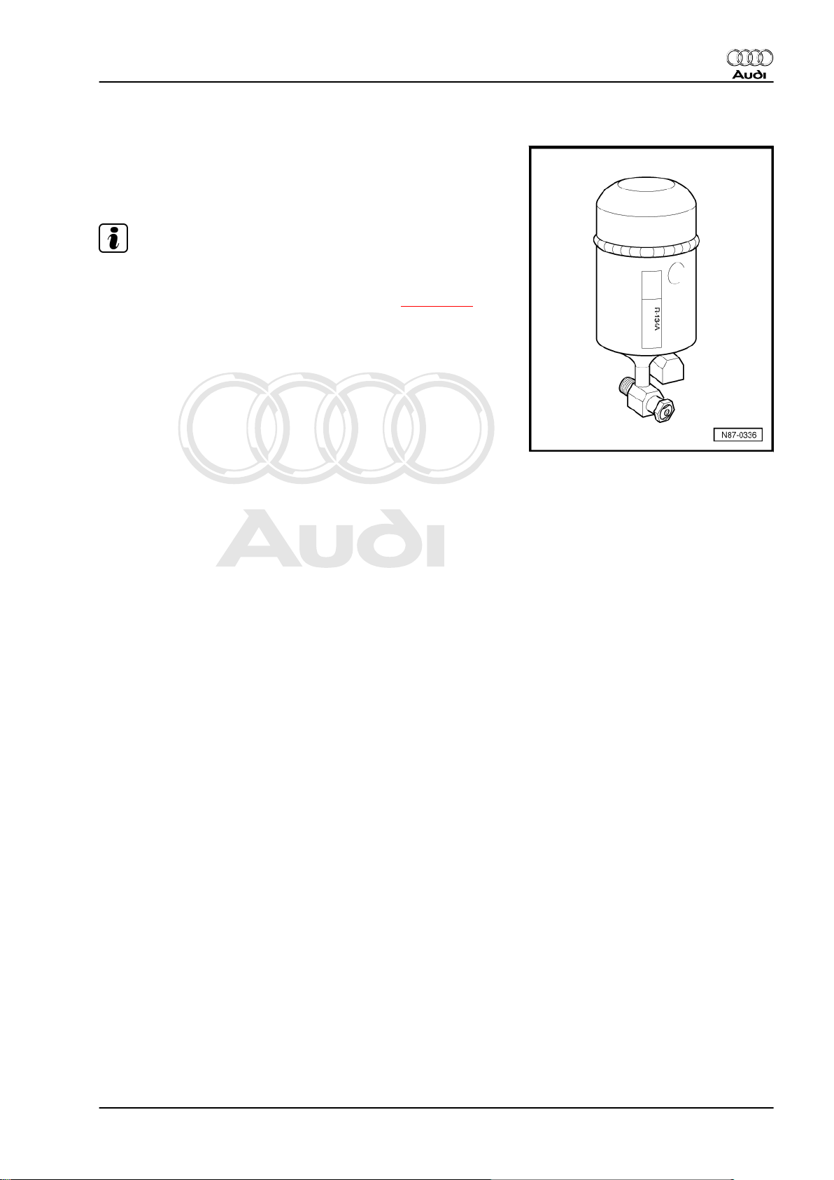
1.4 Refrigerant R134a
Vehicle air conditioning systems make use of the vaporisation and
condensation process. These systems employ a substance with
a low boiling point, referred to as refrigerant.
The refrigerant used is tetrafluoroethane R134a, which boils at
-26.5°C at a vapour pressure of „1 bar“.
♦ Physical properties of refrigerant R134a ⇒ page 5
4 Rep. gr.87 - Air conditioning system
Page 9
Protected by copyright. Copying for private or commercial purposes, in part or in whole, is not
permitted unless authorised by AUDI AG. AUDI AG does not guarantee or accept any liability
with respect to the correctness of information in this document. Copyright by AUDI AG.
Audi 100 1991 ➤ , Audi 80 1992 ➤ , Audi A1 2011 ➤ , Audi A2 2001 ➤ , A ...
Air conditioner with refrigerant R134a - Edition 06.2010
♦ Critical point ⇒ page 5
♦ Environmental aspects of refrigerant R134a ⇒ page 5
1.4.1 Physical properties of refrigerant R134a
Chemical formula CH2F–CF3 or CF3–CH2F
Chemical designation Tetrafluoroethane
Boiling point at 1 bar -26.5 °C
Solidification point -101.6 °C
Critical temperature 100.6 °C
Critical pressure 40.56 bar (absolute)
1.4.2 Critical point
The critical point (critical temperature and critical pressure) is that
above which there is no longer a boundary between liquid and
gas.
A substance above its critical point is always in the gaseous state.
At temperatures below the critical point, all types of refrigerant in
pressure vessels exhibit both a liquid and a gas phase, i.e. there
is a layer of gas above the liquid.
As long as both liquid and gas are present in the vessel, the pres‐
sure is governed by ambient temperature ⇒ page 3 „Vapour
pressure table“.
Note
Different types of refrigerant must never be mixed. The refrigerant
specified for the respective air conditioning system must be used
exclusively.
1.4.3 Environmental aspects of refrigerant R134a
♦ R134a is a fluorocarbon and contains no chlorine.
♦ R134a has a shorter atmospheric lifespan than refrigerant
R12.
♦ R134a does not damage the ozone layer, the ozone depletion
potential is zero.
♦ The global warming potential (GWP) of R134a is 1300 (the
GWP of carbon dioxide = 1).
♦ The global warming effect of R134a is ten times less than that
of refrigerant R12.
1.5 Properties of refrigerant R134a
♦ Trade names and designations ⇒ page 6
♦ Colour ⇒ page 6
♦ Vapour pressure ⇒ page 6
♦ Physical properties of R134a ⇒ page 6
♦ Reaction with metals ⇒ page 6
♦ Critical temperature/critical pressure ⇒ page 6
♦ Water content ⇒ page 7
♦ Combustibility ⇒ page 7
1. General information on air conditioning systems 5
Page 10
Protected by copyright. Copying for private or commercial purposes, in part or in whole, is not
permitted unless authorised by AUDI AG. AUDI AG does not guarantee or accept any liability
with respect to the correctness of information in this document. Copyright by AUDI AG.
Audi 100 1991 ➤ , Audi 80 1992 ➤ , Audi A1 2011 ➤ , Audi A2 2001 ➤ , A ...
Air conditioner with refrigerant R134a - Edition 06.2010
♦ Charge factor ⇒ page 7
♦ Tracing leaks ⇒ page 7
1.5.1 Trade names and designations
The refrigerant R134a is currently available under the following
trade names:
♦ H-FKW 134a
♦ SUVA 134a
♦ KLEA 134a
Note
♦
Different trade names may be used in other countries.
♦
Of the wide range of refrigerants available, this is the only one
which may be used for vehicles. The designations Frigen and
Freon are trade names. They also apply to refrigerants which
should not be used in vehicles.
1.5.2 Colour
Like water, refrigerants are colourless in both vapour and liquid
form. Gas is invisible. Only the boundary layer between gas and
liquid is visible (liquid level in indicator tube of charging cylinder
or bubbles in sight glass). Liquid refrigerant R134a may have a
coloured (milky) appearance in a sight glass. This cloudiness is
caused by partially dissolved refrigerant oil and does not indicate
a fault.
1.5.3 Vapour pressure
In a partially filled, closed vessel, the quantity of refrigerant evap‐
orating from the surface equals the quantity returning to the liquid
state as vapour particles condense. This state of equilibrium oc‐
curs under the influence of pressure and is often called vapour
pressure. Vapour pressure is dependent on temperature
⇒ page 3 „Vapour pressure table“.
1.5.4 Physical properties of R134a
As the vapour pressure curves of R134a and other refrigerants
are sometimes very similar, unequivocal identification cannot be
made simply on the basis of pressure.
When using R134a, the air conditioner compressor is lubricated
by means of special synthetic refrigerant oils, e.g. PAG oils (pol‐
yalkylene glycol oils).
1.5.5 Reaction with metals
In its pure state, refrigerant R134a is chemically stable and does
not corrode iron or aluminium.
However, contamination of the refrigerant, e.g. with chlorine com‐
pounds, leads to the corrosion of certain metals and plastics. This
can result in blockage, leaks or deposits at the air conditioner
compressor piston.
1.5.6 Critical temperature/critical pressure
The refrigerant R134a remains chemically stable up to a gas
pressure of 39.5 bar (corresponding to a temperature of 101 °C).
Above this temperature, the refrigerant decomposes (refer to
"Combustibility").
6 Rep. gr.87 - Air conditioning system
Page 11
Protected by copyright. Copying for private or commercial purposes, in part or in whole, is not
permitted unless authorised by AUDI AG. AUDI AG does not guarantee or accept any liability
with respect to the correctness of information in this document. Copyright by AUDI AG.
Audi 100 1991 ➤ , Audi 80 1992 ➤ , Audi A1 2011 ➤ , Audi A2 2001 ➤ , A ...
Air conditioner with refrigerant R134a - Edition 06.2010
1.5.7 Water content
Only very small amounts of water are soluble in liquid refrigerant.
On the other hand, refrigerant vapour and water vapour mix in
any ratio.
Any water in the refrigerant circuit will be entrained in droplet form
once the dryer in the receiver or reservoir has absorbed as little
as approx. 7 g of water. This water flows as far as the expansion
valve nozzle or the restrictor and turns to ice. The air conditioner
will then no longer provide any cooling effect.
Water causes irreparable damage to the air conditioner because
at high pressures and temperatures it combines with other im‐
purities to form acids.
1.5.8 Combustibility
Refrigerant is non-flammable. In fact it has a fire-inhibiting or fireextinguishing effect. Refrigerant decomposes when exposed to
flames or red-hot surfaces. UV light (produced for example during
electric welding) also causes refrigerant decomposition. The re‐
sultant decomposition products are toxic and must not be inhaled.
However, these chemicals irritate the mucous membranes, giving
adequate warning of their presence.
1.5.9 Charge factor
A vessel must have space for vapour as well as liquid. As the
temperature rises, the liquid expands. The vapour-filled space
becomes smaller. At a certain point, there will only be liquid in the
vessel. Beyond this, even a slight increase in temperature causes
great pressure to build up in the vessel as the liquid attempts to
continue expanding despite the absence of the necessary space.
The resultant forces are sufficient to rupture the vessel. To stop
vessels being overfilled, regulations governing the storage of
compressed gases specify the number of kilograms of refrigerant
with which a vessel may be filled per litre of internal vessel vol‐
ume. The maximum permissible capacity is calculated by multi‐
plying this "charge factor" by the internal volume of the vessel.
The figure for the refrigerant used in motor vehicles is 1.15 kg/
litre.
1.5.10 Tracing leaks
External damage, for example, can cause a leak in the refrigerant
circuit. The small quantity of refrigerant escaping from minor leaks
can be detected for example using an electronic leak detector or
by introducing a leak detection additive into the refrigerant circuit.
Electronic leak detectors are capable of registering leaks with re‐
frigerant losses of less than 5 g per year.
Note
Use must be made for the various refrigerants of leak detectors
designed for the composition of the refrigerant concerned. For
example, a leak detector for R12 refrigerant is not appropriate for
R134a, as R134a refrigerant has no chlorine atoms and the leak
detector therefore does not respond.
1.6 Refrigerant oil
Refrigerant oil mixes with the refrigerant (about 20 - 40 %, de‐
pending on compressor type and amount of refrigerant) and
circulates constantly in the system, lubricating the moving parts.
Special synthetic refrigerant oils, e.g. polyalkylene glycol (PAG)
oil, are used in conjunction with R134a air conditioning systems.
This is necessary as mineral oil, for example, does not mix with
1. General information on air conditioning systems 7
Page 12
Protected by copyright. Copying for private or commercial purposes, in part or in whole, is not
permitted unless authorised by AUDI AG. AUDI AG does not guarantee or accept any liability
with respect to the correctness of information in this document. Copyright by AUDI AG.
Audi 100 1991 ➤ , Audi 80 1992 ➤ , Audi A1 2011 ➤ , Audi A2 2001 ➤ , A ...
Air conditioner with refrigerant R134a - Edition 06.2010
R134a. In addition, the materials of the R134a air conditioning
system could be corroded as a result of mixture flowing through
the refrigerant circuit under pressure at high temperatures or
breakdown of the lubricating film in the air conditioner compres‐
sor. The use of non-approved oils can lead to the failure of the air
conditioning system; exclusive use is therefore to be made of au‐
thorised oils.
⇒ Electronic parts catalogue
Type of oil for R134a in motor vehicles: PAG. (polyalkylene glycol)
Note
♦
Do not store refrigerant oils in open containers as they are
extremely hygroscopic (water-absorbing).
♦
Always keep oil containers sealed.
♦
Do not re-use old refrigerant oil. It must be disposed of as used
oil of unknown origin ⇒ Audi-ServiceNet, HSO Environmental
Protection .
♦
Ester-based oils are only intended for use with large systems
(not for motor vehicle air conditioners).
♦ Properties of refrigerant oil ⇒ page 8
1.6.1 Properties of refrigerant oil
The most important properties are a high degree of solubility with
refrigerant, good lubricity, absence of acid and minimal water
content. It is therefore only permissible to use certain specified
oils. For a list of approved refrigerant oils and capacities, refer to
⇒ page 164 .
PAG oils, which are appropriate for refrigerant R134a, are highly
hygroscopic and do not mix with other oils. Opened containers
should therefore be closed again immediately to prevent ingress
of moisture. Moisture and acids promote the ageing of refrigerant
oil, causing it to become dark, viscous and corrosive towards
metals.
Note
♦
On account of its chemical properties, the refrigerant oil is not
to be disposed of together with engine or gear oil. Refrigerant
oil must be disposed of as used oil of unknown origin ⇒ AudiServiceNet, HSO Environmental Protection .
♦
Only oil approved for the air conditioner compressor is to be
used for refrigerant circuits containing refrigerant R134a ⇒
Electronic parts catalogue and capacities ⇒ page 164 .
1.7 How air conditioning works
The temperature in the passenger compartment depends on the
amount of heat radiated into the vehicle through the windows and
conducted by the metal parts of the body. In hot weather some of
the heat must be pumped off to achieve a more comfortable tem‐
perature for the occupants.
As heat spreads into cooler areas, the passenger compartment
is fitted with a unit for generating low temperatures in which re‐
frigerant is constantly evaporated. The heat required for this is
extracted from the air flowing through the evaporator.
After absorbing heat, the refrigerant is pumped off through the air
conditioner compressor. The work of compression of the air con‐
8 Rep. gr.87 - Air conditioning system
Page 13
Protected by copyright. Copying for private or commercial purposes, in part or in whole, is not
permitted unless authorised by AUDI AG. AUDI AG does not guarantee or accept any liability
with respect to the correctness of information in this document. Copyright by AUDI AG.
Audi 100 1991 ➤ , Audi 80 1992 ➤ , Audi A1 2011 ➤ , Audi A2 2001 ➤ , A ...
Air conditioner with refrigerant R134a - Edition 06.2010
ditioner compressor increases the heat content and temperature
of the refrigerant. Its temperature is then substantially higher than
that of the surrounding air.
The hot refrigerant flows with its heat content to the condenser,
where the refrigerant dissipates its heat to the surrounding air via
the condenser due to the temperature gradient between the re‐
frigerant and the surrounding air.
The refrigerant thus acts as a heat transfer medium. As it is reused, the refrigerant is returned to the evaporator.
For this reason all air conditioning systems are based on the re‐
frigerant circulation principle. There are however differences as
regards the units used.
♦ Comfort of vehicle occupants ⇒ page 9
♦ Environmental aspects ⇒ page 9
1.7.1 Comfort of vehicle occupants
A basic requirement for concentration and safe driving is a feeling
of comfort in the passenger compartment. Especially when con‐
ditions are hot and humid, a good level of comfort can only be
achieved with air conditioning. Comfort can of course also be en‐
hanced by opening windows/the sun roof or increasing the air
output. Such a course of action is however associated with certain
drawbacks for the occupants of the vehicle, e.g. more noise,
draughts, exhaust fumes and unfiltered pollen (unpleasant for al‐
lergy sufferers).
Climate control together with a good heating and ventilation sys‐
tem concept can create a sense of wellbeing and comfort by
regulating the temperature, humidity and air circulation in the
passenger compartment to suit ambient conditions, with the ve‐
hicle both stationary and moving.
Other important advantages of air conditioning:
♦ Purification of the air supplied to the passenger compartment
(dust and pollen, for example, are washed out by the moist fins
of the evaporator and removed with the condensate).
♦ Temperatures in a mid-size car (example: after short travelling
time, ambient temperature 30 °C in the shade and vehicle ex‐
posed to sunlight).
With air conditioning Without air condi‐
tioning
At head height 23 °C 42 °C
At chest level 24 °C 40 °C
In footwell 30 °C 35 °C
1.7.2 Environmental aspects
Since about 1992, the air conditioning systems of newly manu‐
factured cars have been successively changed to refrigerant
R134a. This refrigerant contains no chlorine and therefore does
not deplete the ozone layer.
Up until roughly 1992, refrigerant R12 was used for air condition‐
ing systems. Due to its chlorine atoms, this CFC had a high ozone
depletion potential as well as potential for intensifying the green‐
house effect.
Conversion programmes are available for old existing systems
filled with the ozone-depleting substance R12 ⇒ Workshop Man‐
ual for air conditioners with refrigerant R12 (this Workshop Man‐
ual is available in hardcopy form only).
1. General information on air conditioning systems 9
Page 14
Protected by copyright. Copying for private or commercial purposes, in part or in whole, is not
permitted unless authorised by AUDI AG. AUDI AG does not guarantee or accept any liability
with respect to the correctness of information in this document. Copyright by AUDI AG.
Audi 100 1991 ➤ , Audi 80 1992 ➤ , Audi A1 2011 ➤ , Audi A2 2001 ➤ , A ...
Air conditioner with refrigerant R134a - Edition 06.2010
For environmental reasons, refrigerants must not be released into
the atmosphere ⇒ page 40 (see the relevant environmental leg‐
islation).
1.8 General work safety
♦ In accordance with regulations of the German industrial liabil‐
ity insurance association, VBG 20, (other regulations may
apply in other countries)
♦ Heed the workplace-specific instructions ⇒ Audi-ServiceNet,
HSO Environmental Protection , which are to be displayed at
refrigerant workplaces.
1.9 Product properties
Refrigerants used in motor vehicle air conditioning systems be‐
long to the new generation of refrigerants based on chlorine-free,
partially fluorinated hydrocarbons (H-FKW, R134a; other names
may be used in other countries).
With regard to their physical properties, these are refrigerants
which have been liquefied under pressure. They are subject to
the regulations governing pressure vessels and may only be used
in approved and appropriately marked containers.
Specific requirements must be observed to ensure safe and prop‐
er handling:
1.10 Handling refrigerant
If refrigerant vessels are opened, the contents may escape in liq‐
uid or vapour form. The higher the pressure in the vessel, the
more vigourous the process.
The pressure level is governed by two factors:
• The type of refrigerant in the vessel. „Rule: The lower the boil‐
ing point, the higher the pressure.“
• The temperature level. „Rule: The higher the temperature, the
higher the pressure.“
WARNING
♦ Do not open vessels containing refrigerant.
Wear safety goggles
Put on safety goggles to prevent refrigerant getting into the eyes,
as this could cause severe injury through frostbite.
Wear protective gloves and apron
Grease and oils dissolve readily in refrigerants. They would there‐
fore damage the protective layer of grease if allowed to come into
contact with the skin. Degreased skin is however sensitive to the
cold and germs.
Do not allow liquid refrigerant to come into contact with the skin
The refrigerant draws heat for evaporation from the surrounding
area - even if this is the skin. This may give rise to extremely low
temperatures and result in local frostbite (boiling point of R134a:
-26.5 °C at ambient pressure).
Do not inhale refrigerant vapours
If refrigerant vapour escapes in concentrated form, it mixes with
the surrounding air and displaces the oxygen necessary for
breathing.
10 Rep. gr.87 - Air conditioning system
Page 15
Protected by copyright. Copying for private or commercial purposes, in part or in whole, is not
permitted unless authorised by AUDI AG. AUDI AG does not guarantee or accept any liability
with respect to the correctness of information in this document. Copyright by AUDI AG.
Audi 100 1991 ➤ , Audi 80 1992 ➤ , Audi A1 2011 ➤ , Audi A2 2001 ➤ , A ...
Air conditioner with refrigerant R134a - Edition 06.2010
Smoking is absolutely prohibited
A burning cigarette can cause refrigerant to decompose. The re‐
sultant substances are toxic and must not be inhaled.
Welding and soldering on refrigeration systems
Before performing welding, brazing or soldering work on vehicles
in the vicinity of air conditioning system components, extract re‐
frigerant and remove any remaining refrigerant by blowing out
with nitrogen.
The products of decomposition of the refrigerant arising from the
effect of heat are not only toxic, but also highly corrosive and can
therefore damage pipes and sections of the system. The principal
substance is hydrogen fluoride.
Pungent odour
A pungent odour indicates that the products of decomposition
mentioned above have already formed. Avoid inhaling these sub‐
stances under all circumstances, as otherwise the airways, lungs
and other organs could be damaged.
First aid
• Following accidental contact with eyes or mucous mem‐
branes, immediately rinse with copious amounts of running
water and consult an eye specialist.
• Following accidental contact with the skin, immediately re‐
move clothing affected and rinse skin with copious amounts of
water.
• Following accidental inhalation of concentrated refrigerant va‐
pours, the person concerned must be taken immediately into
the open air. Call a doctor. Administer oxygen in the event of
breathing difficulties. If the person affected is having great dif‐
ficulty breathing or is not breathing at all, tilt back head and
administer artificial respiration.
♦ Handling pressure vessels ⇒ page 11
1.11 Handling pressure vessels
Secure vessels to prevent them falling over.
Secure upright cylinders to stop them falling over and cylinders
lying flat to stop them rolling away.
Pressure vessels must never be thrown.
If dropped, the vessels could be so severely deformed that they
rupture. The refrigerant evaporates immediately, liberating con‐
siderable force. Flying fragments of cylinders can cause severe
injuries.
To protect the valves, cylinders may only be transported with the
protective cap screwed on.
Valves may break off if cylinders are not properly transported.
Never store in the vicinity of radiators.
High temperatures may occur in such areas. High temperatures
are also accompanied by high pressures and the maximum per‐
missible vessel pressure may be exceeded.
Never heat to above 50 °C
To avoid possible risk, pressure vessel regulations specify that
vessels are not to be heated to in excess of 50 °C.
Do not heat in an uncontrolled manner
Do NOT heat with a naked flame. Local overheating can cause
structural changes in the material of the vessel, which then reduce
1. General information on air conditioning systems 11
Page 16

Protected by copyright. Copying for private or commercial purposes, in part or in whole, is not
permitted unless authorised by AUDI AG. AUDI AG does not guarantee or accept any liability
with respect to the correctness of information in this document. Copyright by AUDI AG.
Audi 100 1991 ➤ , Audi 80 1992 ➤ , Audi A1 2011 ➤ , Audi A2 2001 ➤ , A ...
Air conditioner with refrigerant R134a - Edition 06.2010
its ability to withstand pressure. There is also a danger of refrig‐
erant decomposition due to localised overheating.
Sealing empty vessels
Empty refrigerant vessels must always be sealed to prevent the
ingress of moisture. Moisture causes steel containers to rust. This
weakens the vessel walls. In addition, any rust particles which
enter refrigeration systems from storage vessels will cause mal‐
functioning.
1.12 Safety regulations for working with ex‐
traction and charging systems
• Before connecting the charging system to the air conditioning
system, ensure that the shut-off valves are closed.
• Before disconnecting the charging system from the air condi‐
tioning system, ensure that the process has been completed
so that no refrigerant can escape into the atmosphere.
• Once the purified refrigerant from the charging system has
been transferred to an external compressed-gas cylinder,
close the hand shut-off valves at the cylinder and charging
system.
• Do not expose the charging system to moisture or use it in a
wet environment.
• Disconnect from power supply before performing service work
on the charging system.
• An extension cable should not normally be used because it
can increase the fire hazard. If the use of an extension cable
is unavoidable, the minimum cross-section should be 2.5
mm2.
• In case of fire, remove external cylinder.
• Entrained oil from the air conditioning system drawn off by the
suction unit into the measurement vessel supplied is subse‐
quently to be transferred to a sealable container, as it contains
a small quantity of refrigerant which must not be released into
the environment.
• Following shutdown, the air conditioner service station must
be secured to stop it rolling away.
12 Rep. gr.87 - Air conditioning system
Page 17
Protected by copyright. Copying for private or commercial purposes, in part or in whole, is not
permitted unless authorised by AUDI AG. AUDI AG does not guarantee or accept any liability
with respect to the correctness of information in this document. Copyright by AUDI AG.
Audi 100 1991 ➤ , Audi 80 1992 ➤ , Audi A1 2011 ➤ , Audi A2 2001 ➤ , A ...
Air conditioner with refrigerant R134a - Edition 06.2010
1.13 Safety measures for working on vehi‐
cles with air conditioning system and for
handling refrigerant R134a
WARNING
♦ It is advisable to keep an eye bath to hand.
♦ Should liquid refrigerant come into contact with the eyes,
rinse them thoroughly with water for about 15 minutes.
Then administer eye drops and consult a doctor immedi‐
ately even if no pain is felt.
♦ The doctor must be informed that the frostbite was caused
by refrigerant R134a. Should refrigerant come into contact
with other parts of the body despite compliance with the
safety regulations, these must likewise be rinsed immedi‐
ately for approximately 15 minutes with cold water.
♦ Work may only be performed on the refrigerant circuit of
an air conditioning system in well ventilated areas. Switch
on workshop extraction systems, if available.
♦ Refrigerant must not be stored in low-level areas (e.g. cel‐
lars) and their exits or light wells.
• Welding, brazing and soldering work must not be performed
on components of air conditioning system when charged. This
also applies to vehicle welding and soldering work if there is a
danger of air conditioner components becoming hot. When
performing paintwork repairs, the temperature in the drying
booth or preheating zone must not exceed 80 °C.
Reason:
Exposure to heat gives rise to considerable pressure in the sys‐
tem, which could cause the pressure relief valve to open.
Remedy:
– Discharge refrigerant circuit using air conditioner service sta‐
tion.
Note
Damaged or leaking components of the air conditioning system
are not to be repaired by welding or soldering. They must always
be replaced.
Refrigerant vessels (e.g. charging cylinders of air conditioner
service station) must never be subjected to excessive heat or ex‐
posed to direct sunlight.
Remedy:
– Vessels must never be completely filled with liquid refrigerant.
Without sufficient room for expansion (gas cushion), vessels
will rupture with explosive effect in the event of an increase in
temperature ⇒ page 5 .
Refrigerant should never be poured into systems or vessels con‐
taining any air.
Remedy:
– Evacuate systems and containers before charging with refrig‐
erant.
1. General information on air conditioning systems 13
Page 18
Protected by copyright. Copying for private or commercial purposes, in part or in whole, is not
permitted unless authorised by AUDI AG. AUDI AG does not guarantee or accept any liability
with respect to the correctness of information in this document. Copyright by AUDI AG.
Audi 100 1991 ➤ , Audi 80 1992 ➤ , Audi A1 2011 ➤ , Audi A2 2001 ➤ , A ...
Air conditioner with refrigerant R134a - Edition 06.2010
1.14 Basic rules for working on refrigerant cir‐
cuit
♦ General notes ⇒ page 14
♦ Cleaning refrigerant circuit ⇒ page 14 .
♦ Additionally for vehicles with air conditioner compressor with
no magnetic clutch (with air conditioner compressor regulating
valve -N280- ) ⇒ page 15
♦ O-rings ⇒ page 15
1.14.1 General notes
• Heed the workplace-specific instructions ⇒ Audi-ServiceNet,
HSO Environmental Protection .
• Ensure absolute cleanliness when working.
• Wear safety goggles and gloves when working with refrigerant
and nitrogen.
• Switch on workshop extraction systems, if available.
• Always use air conditioner service station to discharge refrig‐
erant circuit, then unfasten screw connections and renew
defective components.
• Use caps to seal off opened assemblies and hoses to prevent
the ingress of moisture and dirt.
• Use only tools and materials intended for refrigerant R134a.
• Seal opened refrigerant oil containers to protect against mois‐
ture.
Note
♦
After completing service work, screw sealing caps (with seals)
onto all connections with valves and service connections.
♦
Before starting up the air conditioning system, heed the vehi‐
cle-specific capacities ⇒ page 144 .
♦
Do not top up refrigerant in circuit; discharge existing refriger‐
ant and re-charge system.
1.14.2 Cleaning refrigerant circuit
The refrigerant circuit must be flushed out with refrigerant R134a
⇒ page 59 (or blown out with compressed air and nitrogen
⇒ page 55 ) in the following cases:
– If moisture or dirt has ingressed into the refrigerant circuit (e.g.
following an accident).
– If the refrigerant oil is dark and viscous.
– If there is too much refrigerant oil in the refrigerant circuit after
compressor replacement.
– If the air conditioner compressor has to be replaced on ac‐
count of „internal“ damage (e.g. noise or no output).
14 Rep. gr.87 - Air conditioning system
Page 19

Protected by copyright. Copying for private or commercial purposes, in part or in whole, is not
permitted unless authorised by AUDI AG. AUDI AG does not guarantee or accept any liability
with respect to the correctness of information in this document. Copyright by AUDI AG.
Audi 100 1991 ➤ , Audi 80 1992 ➤ , Audi A1 2011 ➤ , Audi A2 2001 ➤ , A ...
Air conditioner with refrigerant R134a - Edition 06.2010
Note
When blowing out components with compressed air and nitrogen,
always extract the gas mixture escaping from the components
with suitable extraction units (workshop extraction system).
1.14.3 Additionally for vehicles with air condi‐
tioner compressor with no magnetic
clutch (with air conditioner compressor
regulating valve -N280- )
• The engine is only to be started following complete assembly
of the refrigerant circuit (constant air conditioner compressor
operation).
• If the engine has to be operated with the refrigerant circuit
empty, only do so for as long as absolutely essential and avoid
high engine speeds.
1.14.4 O-rings
♦ Make exclusive use of seals which are resistant to refrigerant
R134a and the related refrigerant oils. Colour coding of O-ring
seals is no longer employed. Black and coloured O-rings are
used.
♦ Pay attention to the correct inside diameter of the seals used
⇒ Electronic parts catalogue , ⇒ Heating, air conditioning;
Rep. gr. 87 and / or ⇒ Air conditioning; Rep. gr. 87 (vehiclespecific workshop manual).
♦ Seals may only be used once.
♦ Before fitting, moisten seals slightly with refrigerant oil (PAG
oil).
1.15 Before using air conditioner after system has been re-charged
– Give the air conditioner compressor approx. 10 turns by hand
by way of the magnetic clutch plate or the pulley.
– Start the engine with the air conditioning system switched off
( air conditioning system magnetic clutch -N25- and air condi‐
tioner compressor regulating valve -N280- are not actuated).
– Switch on the air conditioner compressor once the idling speed
has stabilised and run it for at least 10 minutes at idle in the
maximum cooling output setting.
1. General information on air conditioning systems 15
Page 20
Protected by copyright. Copying for private or commercial purposes, in part or in whole, is not
permitted unless authorised by AUDI AG. AUDI AG does not guarantee or accept any liability
with respect to the correctness of information in this document. Copyright by AUDI AG.
Audi 100 1991 ➤ , Audi 80 1992 ➤ , Audi A1 2011 ➤ , Audi A2 2001 ➤ , A ...
Air conditioner with refrigerant R134a - Edition 06.2010
2 General information on refrigerant
circuit
♦ Components of refrigerant circuit ⇒ page 16
♦ Arrangement of the refrigerant circuit components and their
influence on the high and low-pressure ends ⇒ page 16
♦ Design of refrigerant circuit ⇒ page 25
♦ Connections for quick-release coupling in refrigerant circuit
⇒ page 26
♦ Switches and senders in refrigerant circuit and related con‐
nections ⇒ page 28
♦ Electrical components not fitted in the refrigerant circuit
⇒ page 32 .
♦ Pressures and temperatures in refrigerant circuit
⇒ page 33
♦ Test and measurement operations which can be performed
with a pressure gauge ⇒ page 37
♦ Air conditioner service and recycling units ⇒ page 38
♦ Repair notes for refrigerant circuit ⇒ page 39
2.1 Components of refrigerant circuit
• All components of the refrigerant circuit submitted for quality
observation are always to be sealed (use the original sealing
caps of the replacement part).
• Renew damaged or leaking components of refrigerant circuit
⇒ page 136 .
Note
The following replacement parts (air conditioner compressor, res‐
ervoir, evaporator and condenser) have so far been filled with
nitrogen gas. This charge is being gradually discontinued. Con‐
sequently, no or only very slight pressure equalisation is percep‐
tible on unscrewing the sealing plugs from the replacement part.
2.2 Arrangement of the refrigerant circuit
components and their influence on the
high and low-pressure ends
High-pressure end: Condenser, receiver and restrictor or expan‐
sion valve to separate the high and low-pressure liquid ends.
High pressure results from the restrictor or expansion valve form‐
ing a constriction and causing the refrigerant to accumulate, thus
leading to an increase in pressure and temperature.
Excess pressure occurs if too much refrigerant or refrigerant oil
is used, the condenser is contaminated, the radiator fan is defec‐
tive, the system is blocked or in the event of moisture in the
refrigerant circuit (icing-up of restrictor or expansion valve).
Low-pressure end: Evaporator, evaporator temperature sensor
and air conditioner compressor to separate the high and lowpressure gas ends.
A drop in system pressure can be caused by a loss of refrigerant,
the restrictor or expansion valve (constrictions), a defective air
conditioner compressor or an iced-up evaporator.
16 Rep. gr.87 - Air conditioning system
Page 21

Protected by copyright. Copying for private or commercial purposes, in part or in whole, is not
permitted unless authorised by AUDI AG. AUDI AG does not guarantee or accept any liability
with respect to the correctness of information in this document. Copyright by AUDI AG.
Audi 100 1991 ➤ , Audi 80 1992 ➤ , Audi A1 2011 ➤ , Audi A2 2001 ➤ , A ...
Air conditioner with refrigerant R134a - Edition 06.2010
♦ Air conditioner compressor ⇒ page 18
♦ Condenser ⇒ page 19
♦ Evaporator ⇒ page 19
♦ Reservoir ⇒ page 19
♦ Restrictor ⇒ page 20
♦ Receiver ⇒ page 21
♦ Expansion valve ⇒ page 22
♦ Refrigerant line with internal heat exchanger ⇒ page 22
♦ Quick-release couplings on refrigerant line ⇒ page 23
♦ O-rings ⇒ page 24
♦ Pipes and hoses of refrigerant circuit ⇒ page 24
♦ Pressure relief valve ⇒ page 25
2. General information on refrigerant circuit 17
Page 22
Protected by copyright. Copying for private or commercial purposes, in part or in whole, is not
permitted unless authorised by AUDI AG. AUDI AG does not guarantee or accept any liability
with respect to the correctness of information in this document. Copyright by AUDI AG.
Audi 100 1991 ➤ , Audi 80 1992 ➤ , Audi A1 2011 ➤ , Audi A2 2001 ➤ , A ...
Air conditioner with refrigerant R134a - Edition 06.2010
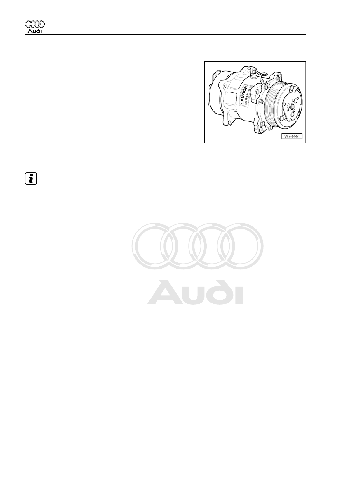
2.2.1 Air conditioner compressor
The air conditioner compressor is driven by the engine via a poly
V-belt or a drive shaft.
Air conditioner compressor with magnetic clutch:
An electromagnetic clutch attached to the air conditioner com‐
pressor provides the power link between the pulley and the com‐
pressor crankshaft when the air conditioning system is switched
on.
Air conditioner compressor with no magnetic clutch:
An overload safeguard attached to the pulley or fitted in the drive
unit of the air conditioner compressor is triggered if the air condi‐
tioner compressor is not running smoothly in order to protect the
belt drive against overload.
The air conditioner compressor draws in refrigerant gas from the
evaporator, compresses it and conveys it to the condenser.
Note
♦
The air conditioner compressor contains refrigerant oil which
mixes with refrigerant R134a at all temperatures.
♦
The rating plate indicates the refrigerant for which the air con‐
ditioner compressor is designed. A valve regulates the pres‐
sure on the low-pressure side within the specified range
(control characteristic).
♦
A regulating valve is actuated externally on air conditioner
compressors with no magnetic clutch.
♦
On air conditioner compressors with no magnetic clutch, the
engine is only to be started following complete assembly of the
refrigerant circuit.
♦
To prevent air conditioner compressor damage if the refriger‐
ant circuit is empty, the magnetic clutch is deactivated and the
air conditioner compressor regulating valve -N280- no longer
actuated (air conditioner compressor idles with engine).
♦
If the refrigerant circuit is empty, an air conditioner compressor
with no air conditioning system magnetic clutch -N25- (with air
conditioner compressor regulating valve -N280- ) is switched
to internal lubrication by way of a valve.
♦
Depending on the version of the air conditioner compressor,
the high-pressure end of the air conditioner compressor may
be fitted with a valve to prevent the backflow of liquid refriger‐
ant into the compressor after switching off the air conditioning
system. If an air conditioner compressor with this valve is fitted
on a vehicle with a refrigerant circuit with an expansion valve,
a relatively long period may elapse before the pressure on the
high-pressure end decreases (the expansion valve is cold and
the pressure on the low-pressure end increases rapidly after
switch-off, the expansion valve closes and the refrigerant can
only flow slowly to the low-pressure end). If the air conditioner
compressor is switched on, the pressure on the low-pressure
end decreases, the expansion valve opens and the refrigerant
can flow to the low-pressure end.
18 Rep. gr.87 - Air conditioning system
Page 23
Protected by copyright. Copying for private or commercial purposes, in part or in whole, is not
permitted unless authorised by AUDI AG. AUDI AG does not guarantee or accept any liability
with respect to the correctness of information in this document. Copyright by AUDI AG.
Audi 100 1991 ➤ , Audi 80 1992 ➤ , Audi A1 2011 ➤ , Audi A2 2001 ➤ , A ...
Air conditioner with refrigerant R134a - Edition 06.2010
2.2.2 Condenser
The condenser dissipates heat from the compressed refrigerant
gas to the surrounding air.
During this process, the refrigerant gas condenses to form liquid.
Note
Depending on the design of the refrigerant circuit, the receiver
may be attached to the condenser or installed in (integrated into)
the condenser ⇒ Heating, air conditioning; Rep. gr. 87 or ⇒ Air
conditioning; Rep. gr. 87 (vehicle-specific workshop manual) and
⇒ Electronic parts catalogue .
2.2.3 Evaporator
The liquid refrigerant evaporates in the coiled pipes of the evap‐
orator. The heat required for this is extracted from the air flowing
past the evaporator fins. The air cools down. The refrigerant
evaporates and is drawn in by the air conditioner compressor to‐
gether with the heat absorbed.
A defined quantity of refrigerant is supplied to the evaporator by
way of a restrictor or expansion valve. In systems with an expan‐
sion valve the flow rate is regulated such that only gaseous
refrigerant emerges at the evaporator outlet.
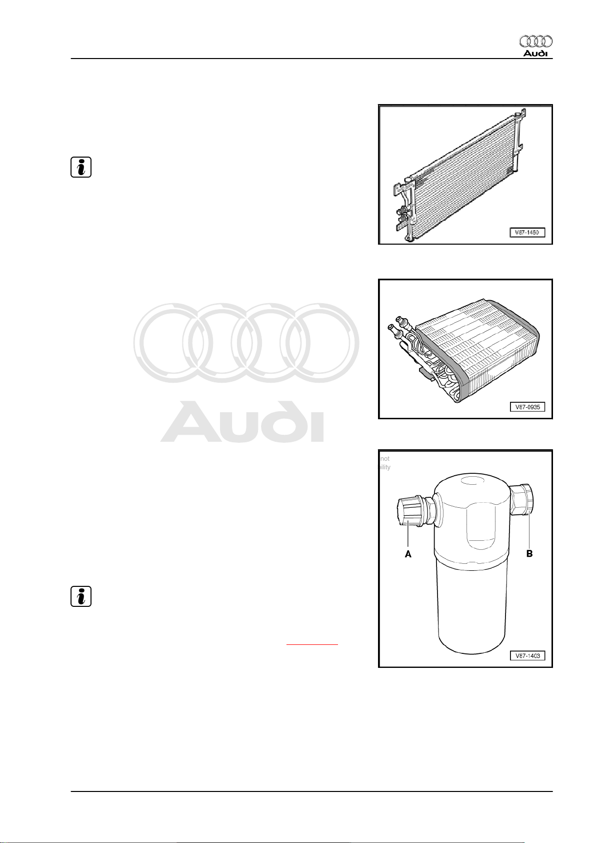
2.2.4 Reservoir
To ensure that the air conditioner compressor draws in only gas‐
eous refrigerant, the reservoir collects the mixture of vapour and
gas coming from the evaporator. The vapour becomes gaseous
refrigerant.
Refrigerant oil entrained in the circuit does not remain in the res‐
ervoir as an oil extraction hole is provided.
Any moisture ingressing into the refrigerant circuit during assem‐
bly is trapped by a filter (desiccant bag) in the reservoir.
Gaseous refrigerant with oil is drawn in by the air conditioner
compressor.
♦
Renew reservoir if refrigerant circuit has been open for a rel‐
atively long period and moisture has ingressed, or if replace‐
ment is stipulated due to a specific complaint ⇒ page 136 .
♦
Do not remove the sealing plugs -A- and -B- until immediately
prior to installation.
♦
If the reservoir is not sealed, the desiccant bag soon becomes
saturated with moisture and thus unusable.
♦
When installing, observe arrow indicating direction of flow (if
applicable).
Note
2. General information on refrigerant circuit 19
Page 24
Protected by copyright. Copying for private or commercial purposes, in part or in whole, is not
permitted unless authorised by AUDI AG. AUDI AG does not guarantee or accept any liability
with respect to the correctness of information in this document. Copyright by AUDI AG.
Audi 100 1991 ➤ , Audi 80 1992 ➤ , Audi A1 2011 ➤ , Audi A2 2001 ➤ , A ...
Air conditioner with refrigerant R134a - Edition 06.2010
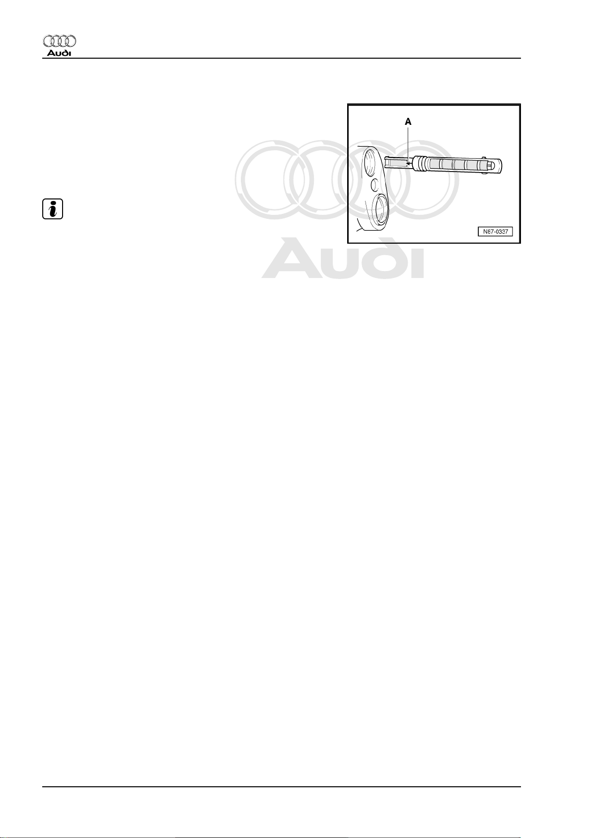
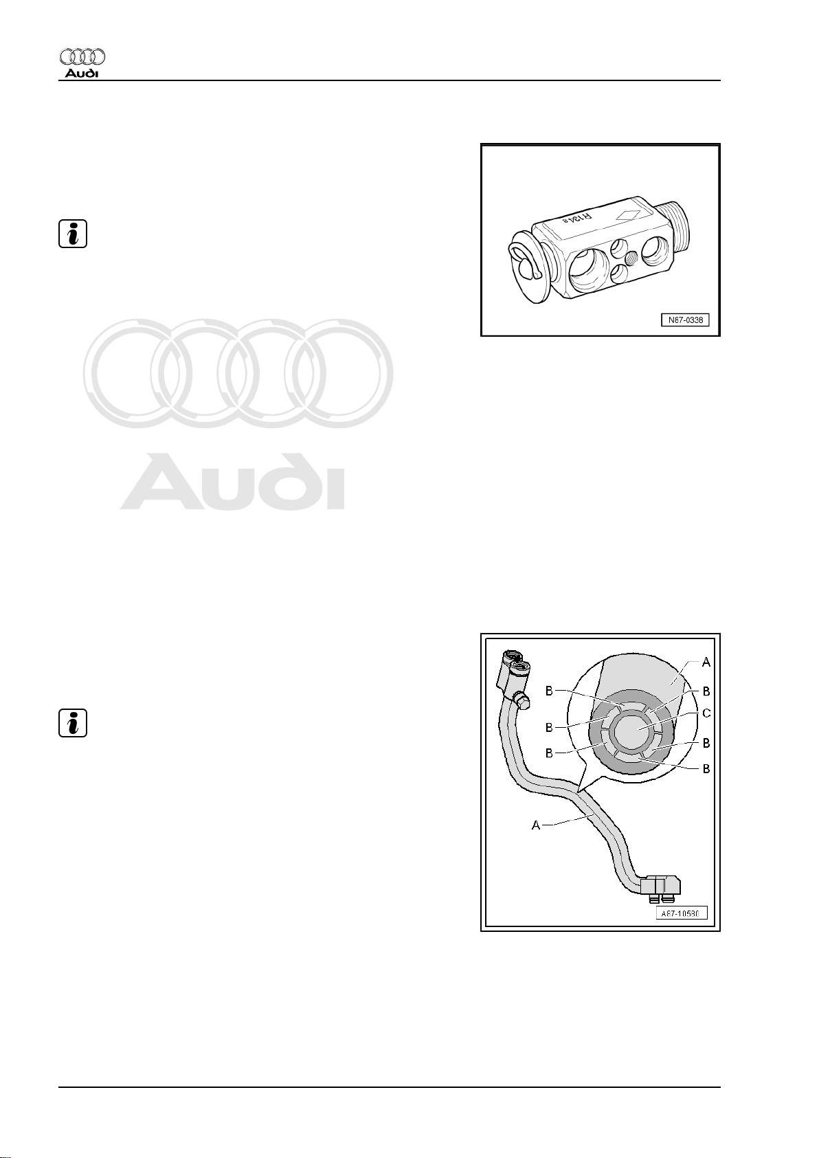
2.2.5 Restrictor
The restrictor creates a constriction. This constriction restricts the
flow, thus separating the refrigerant circuit into a high and lowpressure end. Upstream of the restrictor, the refrigerant is warm
due to the high pressure. Downstream of the restrictor, the refrig‐
erant is cold due to the low pressure. A strainer is provided
upstream of the constriction to trap dirt. The strainer downstream
of the constriction is designed to atomise the refrigerant before it
enters the evaporator.
Note
♦
Arrow -A- on restrictor faces evaporator.
♦
Always replace after opening the circuit.
♦
Different versions exist; heed the applicable notes in the var‐
ious service information booklets ⇒ Heating, air conditioning;
Rep. gr. 87 or ⇒ Air conditioning; Rep. gr. 87 (vehicle-specific
workshop manual) and ⇒ Electronic parts catalogue .
20 Rep. gr.87 - Air conditioning system
Page 25
Protected by copyright. Copying for private or commercial purposes, in part or in whole, is not
permitted unless authorised by AUDI AG. AUDI AG does not guarantee or accept any liability
with respect to the correctness of information in this document. Copyright by AUDI AG.
Audi 100 1991 ➤ , Audi 80 1992 ➤ , Audi A1 2011 ➤ , Audi A2 2001 ➤ , A ...
Air conditioner with refrigerant R134a - Edition 06.2010
2.2.6 Receiver
The receiver collects the droplets of liquid and conveys them in a
continuous stream to the expansion valve. Any moisture ingress‐
ing into the refrigerant circuit during assembly is collected by a
dryer in the receiver.
Note
♦
Renew receiver if refrigerant circuit has been open for a rela‐
tively long period and moisture has ingressed, or if replace‐
ment is stipulated due to a specific complaint ⇒ page 136 .
♦
Do not remove the sealing plugs until immediately prior to in‐
stallation.
♦
If the receiver is not sealed, the desiccant bag soon becomes
saturated with moisture and thus unusable.
♦
When installing, observe arrow indicating direction of flow (if
applicable).
♦
Depending on the design of the refrigerant circuit, the receiver
may also be attached to the condenser or installed in (inte‐
grated into) the condenser ⇒ Heating, air conditioning; Rep.
gr. 87 or ⇒ Air conditioning; Rep. gr. 87 (vehicle-specific
workshop manual) and ⇒ Electronic parts catalogue .
♦
The procedure for dealing with problems differs depending on
the version of the receiver / dryer cartridge. If, for example, the
receiver is attached to the condenser, it can be replaced to‐
gether with the dryer cartridge. If, for example, the receiver is
integrated into the condenser, it is usually possible to replace
the dryer cartridge and any additional filter element separately.
If the receiver is integrated into the condenser and it is not
possible to replace the receiver/dryer cartridge separately, it
may be necessary to replace the entire condenser ⇒ Heating,
air conditioning; Rep. gr. 87 or ⇒ Air conditioning; Rep. gr.
87 (vehicle-specific workshop manual) and ⇒ Electronic parts
catalogue .
♦
Depending on the design of the refrigerant circuit, the desic‐
cant bag (dryer cartridge) may also be installed in the con‐
denser ⇒ Heating, air conditioning; Rep. gr. 87 or ⇒ Air
conditioning; Rep. gr. 87 (vehicle-specific workshop manual)
and ⇒ Electronic parts catalogue .
2. General information on refrigerant circuit 21
Page 26
Protected by copyright. Copying for private or commercial purposes, in part or in whole, is not
permitted unless authorised by AUDI AG. AUDI AG does not guarantee or accept any liability
with respect to the correctness of information in this document. Copyright by AUDI AG.
Audi 100 1991 ➤ , Audi 80 1992 ➤ , Audi A1 2011 ➤ , Audi A2 2001 ➤ , A ...
Air conditioner with refrigerant R134a - Edition 06.2010
2.2.7 Expansion valve
The expansion valve atomises the refrigerant flowing in and con‐
trols the flow rate in line with the quantity of heat transferred such
that it does not become gaseous before reaching the evaporator
outlet.
Note
♦
Pay attention to the correct part number on replacing the ex‐
pansion valve ⇒ Electronic parts catalogue .
♦
Different characteristic curves matched to the appropriate cir‐
cuit ⇒ Heating, air conditioning; Rep. gr. 87 or ⇒ Air condi‐
tioning; Rep. gr. 87 (vehicle-specific workshop manual) and
⇒ Electronic parts catalogue .
♦
Depending on the version of the air conditioner compressor,
the high-pressure end of the air conditioner compressor may
be fitted with a valve to prevent the backflow of liquid refriger‐
ant into the compressor after switching off the air conditioning
system. If an air conditioner compressor with this valve is fitted
on a vehicle with a refrigerant circuit with an expansion valve,
a relatively long period may elapse before the pressure on the
high-pressure end decreases (the expansion valve is cold and
the pressure on the low-pressure end increases rapidly after
switch-off, the expansion valve closes and the refrigerant can
only flow slowly to the low-pressure end). If the air conditioner
compressor is switched on, the pressure on the low-pressure
end decreases, the expansion valve opens and the refrigerant
can flow to the low-pressure end.
2.2.8 Refrigerant line with internal heat ex‐
changer
In this refrigerant line, the hot refrigerant (liquid) flowing through
the high-pressure side gives off energy to the cold refrigerant
(gaseous or vaporous) flowing through the low-pressure side,
thus enhancing the efficiency of the air conditioner.
Note
This illustration shows a refrigerant pipe with an internal heat ex‐
changer as fitted for example on the Audi A4 2008 > and the Audi
A5 Coupé 2008 > ⇒ Air conditioning; Rep. gr. 87 (vehicle-specific
workshop manual).
A - Refrigerant line with internal heat exchanger
B - Channels in the refrigerant line in which the hot liquid refrig‐
erant flows to the evaporator (high-pressure end of the refrigerant
circuit).
C - Channel in the refrigerant line in which the cold refrigerant gas
or vapour flows to the air conditioner compressor (low-pressure
end of the refrigerant circuit).
22 Rep. gr.87 - Air conditioning system
Page 27
Protected by copyright. Copying for private or commercial purposes, in part or in whole, is not
permitted unless authorised by AUDI AG. AUDI AG does not guarantee or accept any liability
with respect to the correctness of information in this document. Copyright by AUDI AG.
Audi 100 1991 ➤ , Audi 80 1992 ➤ , Audi A1 2011 ➤ , Audi A2 2001 ➤ , A ...
Air conditioner with refrigerant R134a - Edition 06.2010
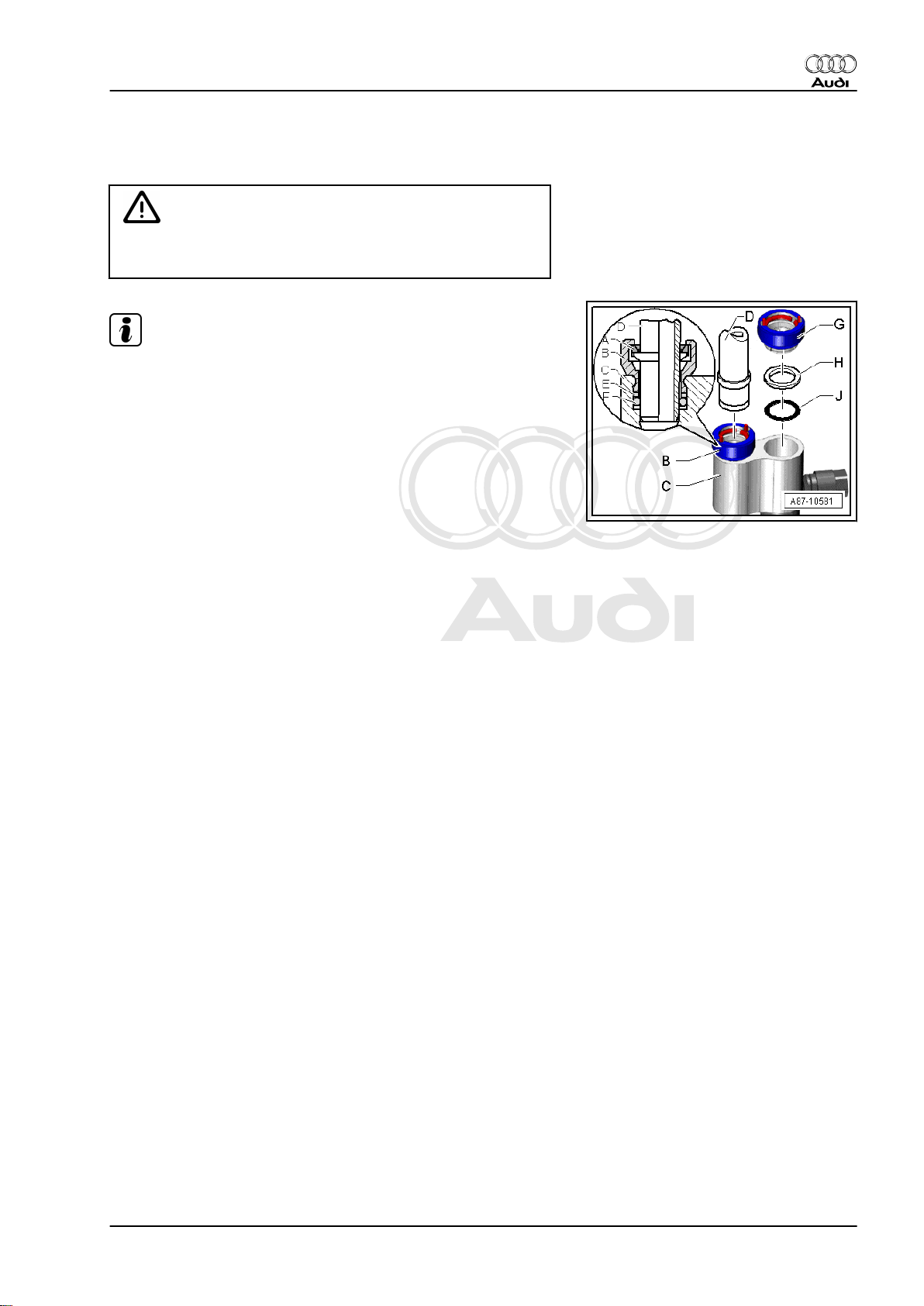
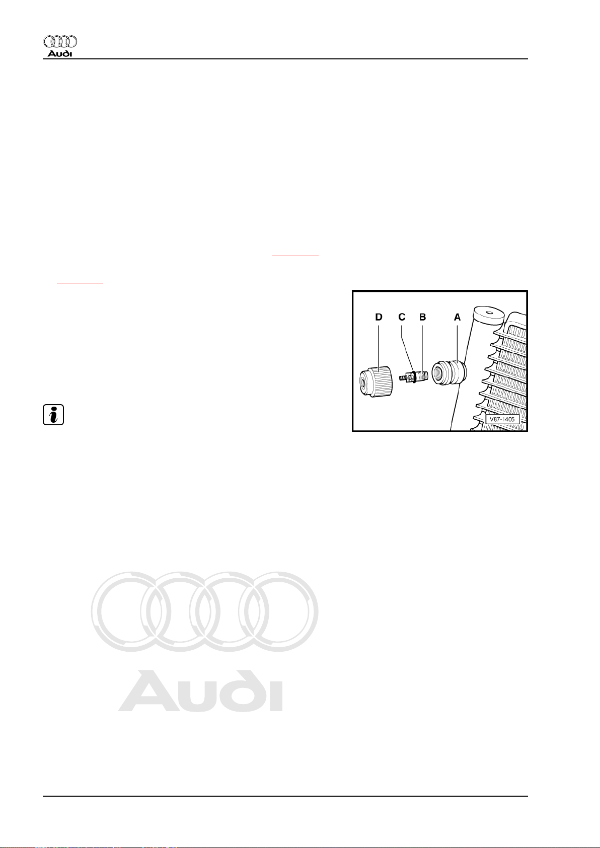
2.2.9 Quick-release couplings on refrigerant line
WARNING
Only release and open the quick-release couplings after com‐
pletely discharging the refrigerant circuit.
Note
♦
This illustration shows the quick-release couplings with a re‐
frigerant pipe with an internal heat exchanger as fitted for
example on the Audi A4 2008 > and the Audi A5 Coupé 2008
> ⇒ Air conditioning; Rep. gr. 87 (vehicle-specific workshop
manual).
♦
Removal of the refrigerant line -D- involves opening the re‐
taining ring -A- with the air conditioner line release tool T40149/- for example ⇒ Air conditioning; Rep. gr. 87 (vehiclespecific workshop manual).
♦
Following removal of the applicable refrigerant pipe, the quickrelease couplings -B- and -G- are to be replaced together with
the corresponding support ring -E- or -H- and the correspond‐
ing O-ring -F- or -J- ⇒ Air conditioning; Rep. gr. 87 (vehiclespecific workshop manual) and ⇒ Electronic parts catalogue .
A - Retaining ring (in quick-release coupling, high-pressure side)
B - Quick-release coupling with retaining ring ( „high-pressure
side“)
C - Refrigerant pipe with an internal heat exchanger
D - Refrigerant line ( „high-pressure side“)
E - Support ring ( „high-pressure side“)
F - O-ring ( „high-pressure side“)
G - Quick-release coupling with retaining ring ( „low-pressure
side“)
H - Support ring ( „low-pressure side“)
J - O-ring ( „low-pressure side“)
2. General information on refrigerant circuit 23
Page 28
Protected by copyright. Copying for private or commercial purposes, in part or in whole, is not
permitted unless authorised by AUDI AG. AUDI AG does not guarantee or accept any liability
with respect to the correctness of information in this document. Copyright by AUDI AG.
Audi 100 1991 ➤ , Audi 80 1992 ➤ , Audi A1 2011 ➤ , Audi A2 2001 ➤ , A ...
Air conditioner with refrigerant R134a - Edition 06.2010
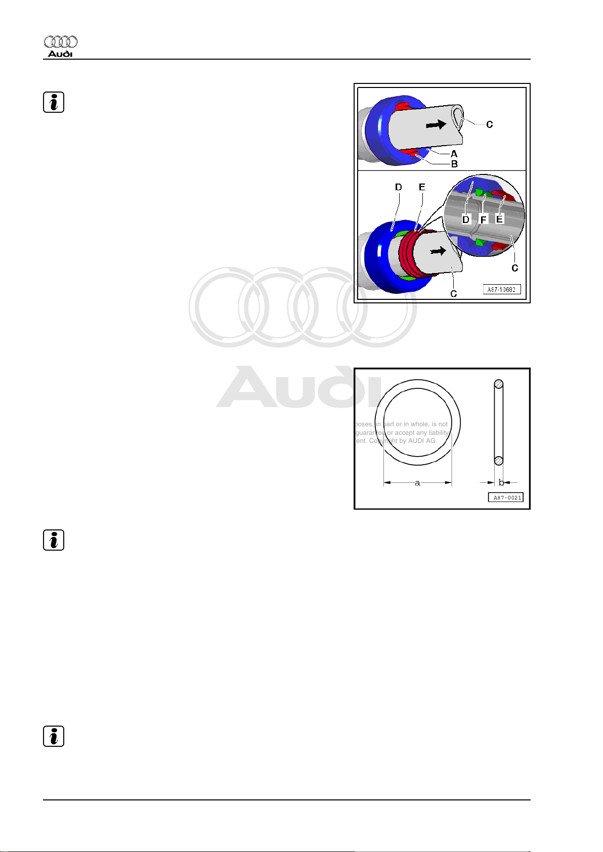
Note
♦
♦
There are different versions -A- and -D- of the quick-release
couplings. With both versions of these quick-release cou‐
plings, the refrigerant lines -C- can be released in the identical
manner using the air conditioner line release tool -T40149/1for example and removed.
♦
With the quick-release coupling -A- fitted at the start of pro‐
duction, the pins -B- become visible after fitting the refrigerant
line -C- if the locked refrigerant line -C- is pulled in arrow di‐
rection.
♦
With the quick-release coupling -A- to be gradually introduced
as of Model Year 2010, the refrigerant line -C- is fitted in the
same manner as for the quick-release coupling -A-. If, with this
version, the refrigerant line -C- is pulled in arrow direction fol‐
lowing assembly, the snap ring -E- emerges from the quickrelease coupling -D- to show that the retaining ring -F- and the
refrigerant line -C- are fully locked. The snap ring -E- is then
to be detached from the refrigerant line -C-.
2.2.10 O-rings
These rings seal the joints between the individual components of
the refrigerant circuit.
Only O-rings resistant to R134a refrigerant and the related refrig‐
erant oils are to be used. This is guaranteed if genuine replace‐
ment parts are used.
O-rings:
– Use only once.
– Observe correct diameters -a- and -b-.
– Moisten with refrigerant oil before fitting ⇒ Heating, air condi‐
tioning; Rep. gr. 87 or ⇒ Air conditioning; Rep. gr. 87 (vehiclespecific workshop manual) and ⇒ Electronic parts catalogue .
Note
The colour coding of O-rings for R134a refrigerant circuits has
been discontinued. Use is made of black and coloured O-rings ⇒
Electronic parts catalogue and ⇒ Heating, air conditioning; Rep.
gr. 87 or ⇒ Air conditioning; Rep. gr. 87 (vehicle-specific work‐
shop manual).
2.2.11 Pipes and hoses of refrigerant circuit
The mixture of refrigerant oil and refrigerant R134a corrodes cer‐
tain metals (e.g. copper) and alloys and dissolves certain hose
materials. Therefore, always use genuine replacement parts.
The pipes and hoses are held together by bolted joints or by way
of special connectors.
Note
Observe specified torques for bolted joints and use the specified
release tools for connectors.
24 Rep. gr.87 - Air conditioning system
Page 29
Protected by copyright. Copying for private or commercial purposes, in part or in whole, is not
permitted unless authorised by AUDI AG. AUDI AG does not guarantee or accept any liability
with respect to the correctness of information in this document. Copyright by AUDI AG.
Audi 100 1991 ➤ , Audi 80 1992 ➤ , Audi A1 2011 ➤ , Audi A2 2001 ➤ , A ...
Air conditioner with refrigerant R134a - Edition 06.2010
2.2.12 Pressure relief valve
The pressure relief valve is attached to the air conditioner com‐
pressor or receiver.
The valve opens at a pressure of approx. 38 bar and closes again
when the pressure has dropped (approx. 30 bar).
Not all the refrigerant escapes.
Certain versions feature a transparent plastic disc which breaks
off as soon as the valve responds.
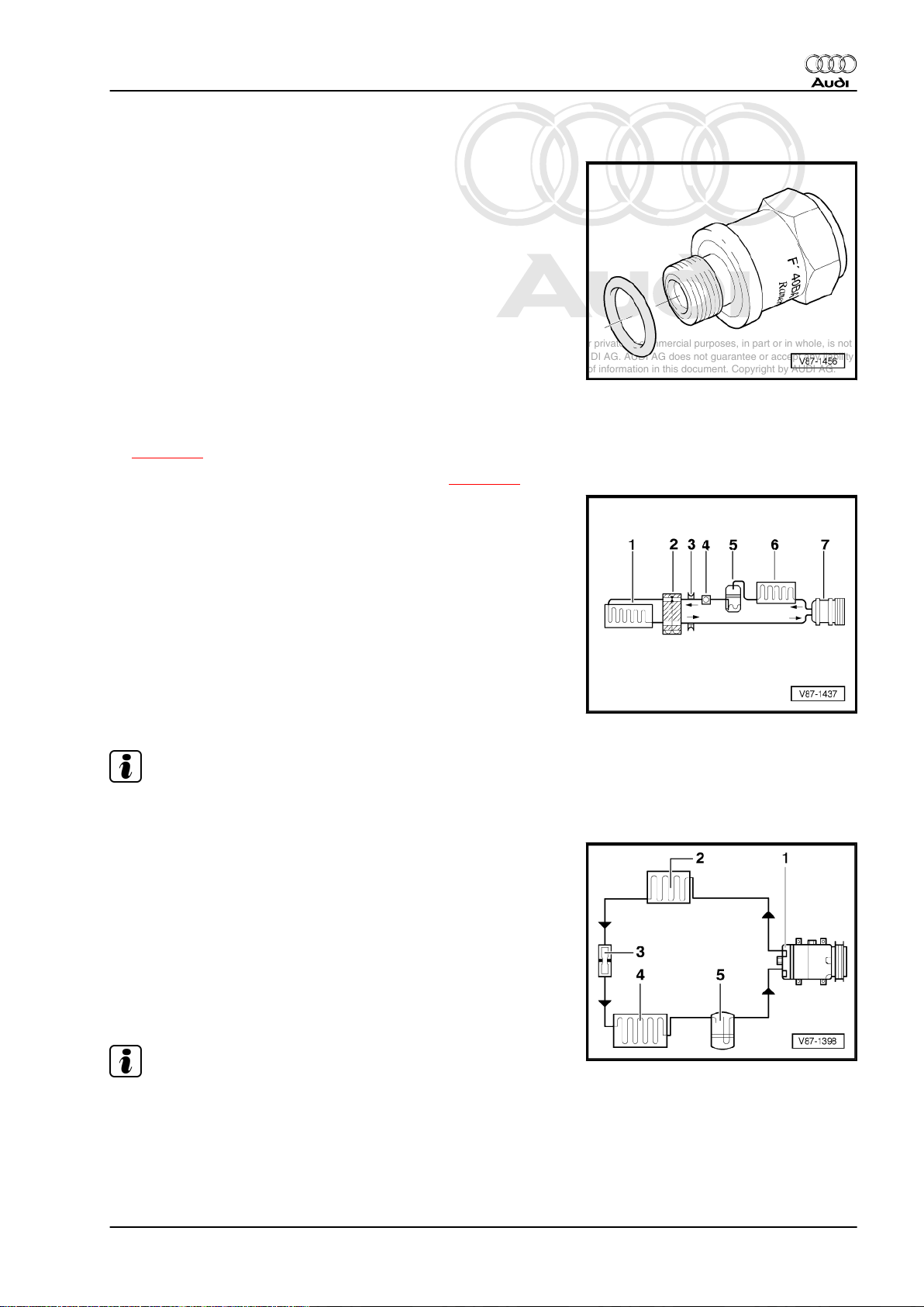
2.3 Design of refrigerant circuit
♦ Refrigerant circuit with expansion valve and evaporator
⇒ page 25
♦ Refrigerant circuit with restrictor and reservoir ⇒ page 25
2.3.1 Refrigerant circuit with expansion valve
and evaporator
1 - Evaporator
2 - Expansion valve
3 - Valve for extraction, charging and measurement
4 - Sight glass (not fitted with R134a circuits)
5 - Receiver with dryer
6 - Condenser
7 - Air conditioner compressor
Note
Arrows show direction of refrigerant flow.
2.3.2 Refrigerant circuit with restrictor and
reservoir
1 - Air conditioner compressor
2 - Condenser
3 - Restrictor
4 - Evaporator
5 - Reservoir
Note
Arrows show direction of refrigerant flow.
2. General information on refrigerant circuit 25
Page 30
Protected by copyright. Copying for private or commercial purposes, in part or in whole, is not
permitted unless authorised by AUDI AG. AUDI AG does not guarantee or accept any liability
with respect to the correctness of information in this document. Copyright by AUDI AG.
Audi 100 1991 ➤ , Audi 80 1992 ➤ , Audi A1 2011 ➤ , Audi A2 2001 ➤ , A ...
Air conditioner with refrigerant R134a - Edition 06.2010
2.4 Connections for quick-release coupling in refrigerant circuit
• Only valves and connections resistant to R134a refrigerant
and the related refrigerant oils are to be used.
• There are different connections (outer diameter) for high and
low-pressure sides.
• Discharge refrigerant circuit before removing valves or valve
cores.
• Always screw on sealing caps.
Layout in vehicle ⇒ Heating, air conditioning; Rep. gr. 87 or ⇒
Air conditioning; Rep. gr. 87 (vehicle-specific Workshop Manual).
♦ Connections with Schrader valve (needle valve) ⇒ page 26
♦ Connections with primary sealing valve (ball valve)
⇒ page 27
2.4.1 Connections with Schrader valve (nee‐
dle valve)
♦ -A- Service connection (soldered in)
♦ -B- Valve core (designation: Schrader valve or needle valve)
♦ -C- O-ring (for valve)
♦ -D- Sealing cap with seal
Note
♦
Following connection, carefully screw the handwheel of the
service coupling into the quick-release coupling adapter to the
extent required to reliably open the valve in the service con‐
nection (observe the pressure gauge; take care not to open
the valve too far).
♦
To remove and install the valve core -B- with the refrigerant
circuit drained, make use of an adapter from the socket T10364- for example.
♦
Take care when tightening valve core -B- (low torque).
♦
There are different versions of these valves and the tightening
torques therefore also differ. The tightening torque for a valve
insert -B- with a VG5 thread (5.2 x 0.7 mm, tyre valve) is
0.4 Nm +- 0.1 Nm. For a valve insert with an M6 x 0.75 mm
thread, the tightening torque is 0.9 Nm +- 0.1 Nm and for a
valve insert with an M8 x 1.0 mm thread it is 2.0 Nm +- 0.2 Nm.
♦
There are different versions of these valves, the valve cores
and the corresponding sealing caps. Attention is to be paid to
the correct version of the valve core and correct assignment
of the sealing caps ⇒ Electronic parts catalogue .
26 Rep. gr.87 - Air conditioning system
Page 31

Protected by copyright. Copying for private or commercial purposes, in part or in whole, is not
permitted unless authorised by AUDI AG. AUDI AG does not guarantee or accept any liability
with respect to the correctness of information in this document. Copyright by AUDI AG.
Audi 100 1991 ➤ , Audi 80 1992 ➤ , Audi A1 2011 ➤ , Audi A2 2001 ➤ , A ...
Air conditioner with refrigerant R134a - Edition 06.2010
2.4.2 Connections with primary sealing valve (ball valve)
WARNING
Before unscrewing connection, connect air conditioner service
station and extract refrigerant. The refrigerant circuit must be
empty; danger of injury.
Connection with high-pressure valve
1 - Connection with internal thread (soldered in)
2 - O-ring (version and identification: black or coloured ⇒ Elec‐
tronic parts catalogue )
3 - Valve with external thread and groove for O-ring (designa‐
tion: Ball valve)
4 - Seal for sealing cap
5 - Sealing cap
Note
♦
Following connection, carefully screw the handwheel of the
service coupling into the quick-release coupling adapter to the
extent required to reliably open the valve in the service con‐
nection (observe the pressure gauge; take care not to open
the valve too far).
♦
To remove and install the valve -3- with the refrigerant circuit
drained, make use of an adapter from the socket -T10364- for
example.
♦
There are different versions of these valves (with internal or
external thread) and the tightening torques may therefore also
differ. The tightening torque for the valves -3- used at present
with an M12 x 1.5 mm external thread is 9 Nm +- 1 Nm.
♦
There are different versions of these valves and the corre‐
sponding sealing caps. Attention is to be paid to the correct
version of the valve and correct assignment of the sealing cap
⇒ Electronic parts catalogue .
2. General information on refrigerant circuit 27
Page 32

Protected by copyright. Copying for private or commercial purposes, in part or in whole, is not
permitted unless authorised by AUDI AG. AUDI AG does not guarantee or accept any liability
with respect to the correctness of information in this document. Copyright by AUDI AG.
Audi 100 1991 ➤ , Audi 80 1992 ➤ , Audi A1 2011 ➤ , Audi A2 2001 ➤ , A ...
Air conditioner with refrigerant R134a - Edition 06.2010
Connection with low-pressure valve
1 - Connection with external thread and groove for O-ring (sol‐
dered in)
2 - O-ring (version and identification: black or coloured ⇒ Elec‐
tronic parts catalogue )
3 - Valve with internal thread
4 - Seal for sealing cap
5 - Sealing cap
Note
♦
Carefully screw the handwheel of the service coupling into the
quick-release coupling adapter to the extent required to relia‐
bly open the valve in the service connection (observe the
pressure gauge; take care not to open the valve too far).
♦
To remove and install the valve -3- with the refrigerant circuit
drained, make use of an adapter from the socket -T10364- for
example.
♦
There are different versions of these valves (with internal or
external thread) and the tightening torques may therefore also
differ. The tightening torque for the valves -3- used at present
with an M10 x 1.25 mm internal thread is 9 Nm +- 1 Nm.
♦
There are different versions of these valves and the corre‐
sponding sealing caps. Attention is to be paid to the correct
version of the valve and correct assignment of the sealing cap
⇒ Electronic parts catalogue .
2.5 Switches and senders in refrigerant cir‐
cuit and related connections
Note
Refer to vehicle-specific refrigerant circuit for switching pres‐
sures, switch removal/installation and switch layout/design ⇒
Heating, air conditioning; Rep. gr. 87 or ⇒ Air conditioning; Rep.
gr. 87 (vehicle-specific workshop manual).
♦ High-pressure switch for air conditioning system -F23-
⇒ page 29
♦ High-pressure switch for magnetic clutch -F118-
⇒ page 29
♦ Low-pressure switch for air conditioning system -F73-
⇒ page 29
♦ Air conditioning system pressure switch -F129- ⇒ page 30
♦ High-pressure sender -G65- ⇒ page 30
♦ Refrigerant pressure and temperature sender -G395-
⇒ page 31
♦ Connections with valve for refrigerant circuit switches
⇒ page 29
♦ Air conditioner compressor regulating valve -N280-
⇒ page 31
♦ Air conditioning system compressor speed sender -G111-
⇒ page 32
28 Rep. gr.87 - Air conditioning system
Page 33

Protected by copyright. Copying for private or commercial purposes, in part or in whole, is not
permitted unless authorised by AUDI AG. AUDI AG does not guarantee or accept any liability
with respect to the correctness of information in this document. Copyright by AUDI AG.
Audi 100 1991 ➤ , Audi 80 1992 ➤ , Audi A1 2011 ➤ , Audi A2 2001 ➤ , A ...
Air conditioner with refrigerant R134a - Edition 06.2010
♦ Refrigerant temperature sender -G454- ⇒ page 32
2.5.1 High-pressure switch for air conditioning
system -F23-
Function:
Switches the radiator fan up to the next speed setting in the event
of a pressure increase in the refrigerant circuit (approx. 16 bar).
2.5.2 High-pressure switch for magnetic
clutch -F118-
Function:
Switches off the air conditioner compressor in the event of excess
pressure in the refrigerant circuit (approx. 32 bar).
2.5.3 Low-pressure switch for air conditioning
Function:
Switches off the air conditioner compressor in the event of a pres‐
sure drop in the refrigerant circuit (approx. 2 bar).
system -F73-
2.5.4 Connections with valve for refrigerant circuit switches
• There are different threads for switches on high and low-pres‐
sure sides.
• Only valves and O-rings resistant to R134a refrigerant and the
related refrigerant oils are to be used.
A - Connection (soldered in)
B - O-ring
C - Valve (with O-ring)
Note
To remove and install the valve core -C- with the refrigerant circuit
drained, make use of an adapter from the socket -T10364- for
example (tightening torque ⇒ page 26 ).
2. General information on refrigerant circuit 29
Page 34

Protected by copyright. Copying for private or commercial purposes, in part or in whole, is not
permitted unless authorised by AUDI AG. AUDI AG does not guarantee or accept any liability
with respect to the correctness of information in this document. Copyright by AUDI AG.
Audi 100 1991 ➤ , Audi 80 1992 ➤ , Audi A1 2011 ➤ , Audi A2 2001 ➤ , A ...
Air conditioner with refrigerant R134a - Edition 06.2010
2.5.5 Air conditioning system pressure switch
-F129-
This pressure switch has 3 functions:
1. Switches the radiator fan up to the next speed setting in the
event of a pressure increase (approx. 16 bar) in the refrigerant
circuit.
2. Switches off the air conditioner in the event of excessive pres‐
sure (approx. 32 bar) caused for example by inadequate engine
cooling.
3. Switches off the air conditioner in the event of insufficient pres‐
sure (approx. 2 bar) caused for example by a loss of refrigerant.
Note
The air conditioning system pressure switch -F129- replaces the
high-pressure switch for air conditioning system -F23- , the lowpressure switch for air conditioning system -F73- and the highpressure switch for magnetic clutch -F118- .
2.5.6 High-pressure sender -G65-
The high-pressure sender -G65- is fitted instead of the air condi‐
tioning system pressure switch -F129- or the refrigerant pressure
and temperature sender -G395- .
The refrigerant pressure and temperature sender -G395- ( „grey“
housing at present) and the high-pressure sender -G65- ( „black“
housing at present) currently only differ in terms of the housing
colour and attention is therefore to be paid to the correct assign‐
ment on replacement (part number ⇒ Electronic parts catalogue ).
As these two senders emit different signals, the relevant control
unit can only evaluate the signal to which it has been matched ⇒
Heating, air conditioning; Rep. gr. 87 or ⇒ Air conditioning; Rep.
gr. 87 (vehicle-specific workshop manual).
The high-pressure sender -G65- generates a square-wave signal
or data telegram when voltage is applied. This signal changes
with the pressure in the system.
The downstream control units (radiator fan control unit, engine
control unit, operating and display unit for Climatronic air condi‐
tioning system -E87- , Climatronic control unit -J255- etc.) use this
signal to calculate the pressure in the refrigerant circuit and to
actuate the radiator fans and the air conditioning system magnetic
clutch -N25- accordingly or to modify actuation of the air condi‐
tioner compressor regulating valve -N280- ⇒ Heating, air condi‐
tioning; Rep. gr. 87 or ⇒ Air conditioning; Rep. gr. 87 (vehiclespecific workshop manual).
30 Rep. gr.87 - Air conditioning system
Page 35

Protected by copyright. Copying for private or commercial purposes, in part or in whole, is not
permitted unless authorised by AUDI AG. AUDI AG does not guarantee or accept any liability
with respect to the correctness of information in this document. Copyright by AUDI AG.
Audi 100 1991 ➤ , Audi 80 1992 ➤ , Audi A1 2011 ➤ , Audi A2 2001 ➤ , A ...
Air conditioner with refrigerant R134a - Edition 06.2010
2.5.7 Refrigerant pressure and temperature sender -G395-
The refrigerant pressure and temperature sender -G395- is fitted
instead of the high-pressure sender -G65- .
The refrigerant pressure and temperature sender -G395- ( „grey“
housing at present) and the high-pressure sender -G65- ( „black“
housing at present) currently only differ outwardly in terms of the
housing colour and attention is therefore to be paid to the correct
assignment on replacement (part number ⇒ Electronic parts
catalogue ). As these two senders emit different signals, the rel‐
evant control unit can only evaluate the signal to which it has been
matched ⇒ Heating, air conditioning; Rep. gr. 87 or ⇒ Air con‐
ditioning; Rep. gr. 87 (vehicle-specific workshop manual).
When voltage is applied, the refrigerant pressure and tempera‐
ture sender -G395- exchanges information via the air conditioner
data bus ( „Lin bus“) with the corresponding control unit. The rel‐
evant control unit uses this information to calculate the pressure
and temperature in the refrigerant circuit and any faults detected
are signalled to the control unit.
The temperature measured by the refrigerant pressure and tem‐
perature sender -G395- differs on account of the design of -G395and the fitting location from the actual temperature of the
refrigerant in the refrigerant circuit. It is therefore not evaluated at
present by all control units and used for air conditioner control ⇒
Heating, air conditioning; Rep. gr. 87 or ⇒ Air conditioning; Rep.
gr. 87 (vehicle-specific workshop manual).
This information is used for example by the operating and display
unit, Climatronic control unit -J255- to calculate the pressure in
the refrigerant circuit and to actuate the downstream control units
(radiator fan control unit, engine control unit etc.) by way of the
data bus. These control units then regulate, for example, the ra‐
diator fans and engine accordingly ⇒ Heating, air conditioning;
Rep. gr. 87 or ⇒ Air conditioning; Rep. gr. 87 (vehicle-specific
workshop manual).
2.5.8 Air conditioner compressor regulating valve -N280-
The regulating valve is installed in the air conditioner compressor.
It is actuated by the operating and display unit for Climatronic air
conditioning system -E87- or the Climatronic control unit -J255(possibly via the data bus and an additional control unit depending
on the vehicle) ⇒ Heating, air conditioning; Rep. gr. 87 or ⇒ Air
conditioning; Rep. gr. 87 (vehicle-specific workshop manual).
The pressure in the low-pressure side is influenced by way of the
regulating valve, thus regulating the temperature in the evapora‐
tor.
Note
The air conditioner compressor regulating valve -N280- is part of
the air conditioner compressor and cannot be replaced separate‐
ly.
2. General information on refrigerant circuit 31
Page 36

Protected by copyright. Copying for private or commercial purposes, in part or in whole, is not
permitted unless authorised by AUDI AG. AUDI AG does not guarantee or accept any liability
with respect to the correctness of information in this document. Copyright by AUDI AG.
Audi 100 1991 ➤ , Audi 80 1992 ➤ , Audi A1 2011 ➤ , Audi A2 2001 ➤ , A ...
Air conditioner with refrigerant R134a - Edition 06.2010
2.5.9 Air conditioning system compressor
speed sender -G111-
Inductive sender
The sender pulses (4 per compressor revolution) and the engine
speed enable the operating and display unit for Climatronic air
conditioning system -E87- or the Climatronic control unit -J255to calculate the belt slip.
If the belt slip exceeds a specified value, the air conditioner com‐
pressor is switched off by the control unit via the magnetic clutch.
Note
♦
Fitted in Audi vehicles with compressor driven via poly V-belt
and Zexel compressor ⇒ Heating, air conditioning; Rep. gr.
87 or ⇒ Air conditioning; Rep. gr. 87 (vehicle-specific work‐
shop manual).
♦
The logo of the compressor manufacturer „Zexel“ affixed to the
air conditioner compressor was switched as of year of pro‐
duction 2006 (when the manufacturer's name changed) from
„Zexel“ to the new name „Valeo“.
2.5.10 Refrigerant temperature sender -G454-
The refrigerant temperature sender (with a temperature-sensitive
resistor) is installed, for example, in the high-pressure pipe next
to the air conditioner compressor.
In the refrigerant circuit, there is a direct relationship between
temperature and pressure. If there is insufficient refrigerant in the
circuit, the temperature in the refrigerant circuit during air condi‐
tioner operation will increase more sharply than envisaged for this
pressure.
Note
♦
Fitted, for example, on the Audi Q7 with certain engines ⇒ Air
conditioning; Rep. gr. 87 (vehicle-specific workshop manual)
and ⇒ Current flow diagrams, Electrical fault finding and Fitting
locations
♦
The operating and display unit, Climatronic control unit -J255evaluates the pressure and the temperature in the refrigerant
circuit and switches off the air conditioner compressor if the
temperature increases above the value stored for this pres‐
sure ⇒ Air conditioning; Rep. gr. 87 (vehicle-specific work‐
shop manual) and ⇒ Vehicle diagnostic tester ( „Selfdiagnosis“ or „Guided fault-finding“ function for the air
conditioner).
2.6 Electrical components not installed in refrigerant circuit
♦ Radiator fan control unit -J293- ⇒ page 33
32 Rep. gr.87 - Air conditioning system
Page 37

Protected by copyright. Copying for private or commercial purposes, in part or in whole, is not
permitted unless authorised by AUDI AG. AUDI AG does not guarantee or accept any liability
with respect to the correctness of information in this document. Copyright by AUDI AG.
Audi 100 1991 ➤ , Audi 80 1992 ➤ , Audi A1 2011 ➤ , Audi A2 2001 ➤ , A ...
Air conditioner with refrigerant R134a - Edition 06.2010
2.6.1 Radiator fan control unit -J293-
This control unit activates and deactivates the magnetic clutch
and thus the air conditioner compressor. It switches the radiator
fans and calculates the pressure in the refrigerant circuit on ve‐
hicles with a high-pressure sender -G65- . Refer to ⇒ Current flow
diagrams, Electrical fault finding and Fitting locations, ⇒ Heating,
air conditioning; Rep. gr. 87 or ⇒ Air conditioning; Rep. gr. 87
(vehicle-specific workshop manual).
2.7 Pressures and temperatures in refriger‐
ant circuit
Caution
♦ When working on the refrigerant circuit, observe generally
valid safety precautions and pressure vessel regulations.
The pressures and temperatures in the refrigerant circuit depend
on the instantaneous operating statuses (e.g. engine speed, ra‐
diator fan speed 1, 2, or 3, engine temperature, air conditioner
compressor on or off) as well as environmental influences (e.g.
ambient temperature, humidity, required cooling output).
On vehicles with air conditioner compressor regulating valve N280- the pressure on the low pressure end is altered by actuat‐
ing -N280- .
For this reason, the values given in the following table are only
intended as a rough guide. They are attained at an engine speed
of 1500 to 2000 rpm and an ambient temperature of 20 °C after
about 20 minutes.
Refer to the vehicle-specific refrigerant circuit for the pressure
gauge set measurement connections ⇒ Heating, air conditioning;
Rep. gr. 87 or ⇒ Air conditioning; Rep. gr. 87 (vehicle-specific
workshop manual).
At 20 °C with the engine not running, the pressure in the refrig‐
erant circuit is 4.7 bar ⇒ page 3 (vapour pressure table).
Note
Pressure may be given in various units: 1 MPa (megapascal) cor‐
responds to 10 bar gauge pressure or 145 psi; 1 bar absolute
pressure corresponds to 0 bar gauge pressure, which is roughly
equivalent to atmospheric pressure.
♦ Refrigerant circuit with expansion valve ⇒ page 33
♦ Refrigerant circuit with restrictor and reservoir ⇒ page 35
2.7.1 Refrigerant circuit with expansion valve
HP – High-pressure side of refrigerant circuit
LP – Low-pressure side of refrigerant circuit
2. General information on refrigerant circuit 33
Page 38

Protected by copyright. Copying for private or commercial purposes, in part or in whole, is not
permitted unless authorised by AUDI AG. AUDI AG does not guarantee or accept any liability
with respect to the correctness of information in this document. Copyright by AUDI AG.
Audi 100 1991 ➤ , Audi 80 1992 ➤ , Audi A1 2011 ➤ , Audi A2 2001 ➤ , A ...
Air conditioner with refrigerant R134a - Edition 06.2010
Component State of refrigerant Pressure (bar) Temperature in degrees
-1- Evaporator, from inlet
Vapour
to outlet
-2- Expansion valve Liquid, expanded to va‐
pour
-3- High-pressure switch /
Liquid approx. 14 bar approx. +55 °C
high-pressure sender
-4- Service connection/
Liquid approx. 14 bar approx. +55 °C
high-pressure end
and
-5- Receiver
-6- Condenser From gas (at inlet) via va‐
pour to liquid (at outlet)
-7- Pressure relief valve
Gas approx. 14 bar approx. +65 °C
and
-8- Air conditioner com‐
pressor/high-pressure
end
-9- Air conditioner com‐
Gas
pressor/low-pressure end
-10- Damping chamber
Gas
(not fitted on all vehicles)
and
-11- Service connection/
low-pressure end
centigrade
approx. 1.2 bar 1)1 approx. -7 °C 2)2
approx. 14 bar approx. +55 °C (high-
pressure end), reduced
to -7 °C (low-pressure
end)
approx. 14 bar From approx. +65 °C (at
inlet) to approx. +55 °C
(at outlet)
approx. 1.2 bar 1)1 approx. -1 °C 2)2
approx. 1.2 bar 1)1 approx. -1 °C 2)2
1) 1 - The pressure in a refrigerant circuit with a regulating air conditioner compressor is maintained at approx. 2 bar absolute (corresponding
to approx. 1 bar gauge) despite varying heat transfer and fluctuating engine speeds. This however only applies within the output range of
the air conditioner compressor. If the output limits of the air conditioner compressor are exceeded, the pressure will increase
⇒ page 103 .
2) 2 - The temperature in a refrigerant circuit with a regulating air conditioner compressor is maintained within the regulating range of the
air conditioner compressor despite varying heat transfer and fluctuating engine speeds. This however only applies within the output range
of the air conditioner compressor. If the output limits of the air conditioner compressor are exceeded, the temperature will increase
⇒ page 103 .
Note
♦
Non self-regulating air conditioner compressors are switched
off by the relevant control unit via the air conditioner compres‐
sor regulating valve -N280- at evaporator temperatures below
0 °C.
♦
On vehicles with air conditioner compressor regulating valve N280- the pressure on the low pressure end is altered by
actuating the valve.
♦
On vehicles with two evaporators and two expansion valves,
the temperature and the pressure in the refrigerant circuit cor‐
respond to those on vehicles with only one evaporator and one
expansion valve (parallel connection).
♦
Depending on the design of the refrigerant circuit, a compo‐
nent with an internal heat exchanger may be fitted (e.g. on the
Audi A4 2008 > and the Audi A5 Coupé 2008 > a refrigerant
pipe with an internal heat exchanger). In the internal heat ex‐
changer, the hot refrigerant (liquid) flowing through the highpressure side gives off energy to the cold refrigerant (gaseous
or vaporous) flowing through the low-pressure side, thus en‐
hancing the efficiency of the air conditioner ⇒ page 22 .
34 Rep. gr.87 - Air conditioning system
Page 39

Protected by copyright. Copying for private or commercial purposes, in part or in whole, is not
permitted unless authorised by AUDI AG. AUDI AG does not guarantee or accept any liability
with respect to the correctness of information in this document. Copyright by AUDI AG.
Audi 100 1991 ➤ , Audi 80 1992 ➤ , Audi A1 2011 ➤ , Audi A2 2001 ➤ , A ...
Air conditioner with refrigerant R134a - Edition 06.2010
Arrows show direction of refrigerant flow.
HP – High-pressure side of refrigerant circuit
LP – Low-pressure side of refrigerant circuit
1 - Evaporator
2 - Expansion valve
3 - High-pressure switch / highpressure sender
❑ Different versions de‐
pending on vehicle
4 - Service connection/highpressure end
5 - Receiver
❑ Different versions de‐
pending on vehicle
6 - Condenser
7 - High-pressure safety valve
8 - Air conditioner compressor/
high-pressure end
9 - Air conditioner compressor/
low-pressure end
10 - Damping chamber
❑ Not fitted on all vehicles
11 - Service connection/lowpressure end
2.7.2 Refrigerant circuit with restrictor and reservoir
HP – High-pressure side of refrigerant circuit
LP – Low-pressure side of refrigerant circuit
Component State of refrigerant Pressure (bar) Temperature in degrees
centigrade
-1- Air conditioner com‐
pressor/high-pressure
end
-2- Condenser From gas to vapour to liq‐
-3- Restrictor From liquid to vapour HP end up to 20 bar LP
-4- Evaporator From vapour to gas Greater than 1.0 bar Warmer than -4 °C
-5- Reservoir Gas
Gas Up to 20 bar Up to +70 °C
Up to 20 bar Up to +70 °C
uid
HP end up to +60 °C LP
end greater than 1.0 bar
end warmer than -4 °C
2. General information on refrigerant circuit 35
Page 40

Protected by copyright. Copying for private or commercial purposes, in part or in whole, is not
permitted unless authorised by AUDI AG. AUDI AG does not guarantee or accept any liability
with respect to the correctness of information in this document. Copyright by AUDI AG.
Audi 100 1991 ➤ , Audi 80 1992 ➤ , Audi A1 2011 ➤ , Audi A2 2001 ➤ , A ...
Air conditioner with refrigerant R134a - Edition 06.2010
Component State of refrigerant Pressure (bar) Temperature in degrees
-6- Air conditioner com‐
Gas
pressor/low-pressure end
The pressures on the low-pressure end are maintained at approx.
2 bar absolute (corresponding to approx. 1 bar gauge) by the
„regulating“ air conditioner compressor even at varying engine
speeds. This however only applies within the output range of the
air conditioner compressor. If the output limits of the air condi‐
tioner compressor are exceeded, refer to ⇒ page 103 .
Note
On vehicles with air conditioner compressor regulating valve N280- the pressure on the low pressure end is altered by actuat‐
ing the valve.
Arrows show direction of refrigerant flow.
HP – High-pressure side of refrigerant circuit
LP – Low-pressure side of refrigerant circuit
centigrade
1 - Air conditioner compressor/
high-pressure end
2 - Condenser
3 - Restrictor
4 - Evaporator
5 - Reservoir
6 - Air conditioner compressor/
low-pressure end
36 Rep. gr.87 - Air conditioning system
Page 41

Protected by copyright. Copying for private or commercial purposes, in part or in whole, is not
permitted unless authorised by AUDI AG. AUDI AG does not guarantee or accept any liability
with respect to the correctness of information in this document. Copyright by AUDI AG.
Audi 100 1991 ➤ , Audi 80 1992 ➤ , Audi A1 2011 ➤ , Audi A2 2001 ➤ , A ...
Air conditioner with refrigerant R134a - Edition 06.2010
2.8 Test and measurement operations which can be performed with a pressure gauge
Pressure gauge scales
1 - Temperature scale for refrigerant R134a CF3– CH2F or
CH2F– CF3
2 - Pressure scale
Note
Pressure may be given in various units: 1 MPa (megapascal) cor‐
responds to 10 bar gauge pressure or 145 psi; 1 bar absolute
pressure corresponds to 0 bar gauge pressure, which is roughly
equivalent to atmospheric pressure.
In addition to the pressure scale, pressure gauges may have one
or more temperature scales. The scale values for R134a are as‐
signed according to the vapour pressure table. As different re‐
frigerants develop different vapour pressures at the same
temperature, each temperature scale is marked for the
appropriate refrigerant.
♦ Pressure gauges permit the following test and measurement
operations ⇒ page 37 .
2.8.1 Pressure gauges permit the following
Refrigerant circuit pressure and temperature measurements
♦ The high-pressure gauge measures the pressure and tem‐
perature propagated evenly from the air conditioner compres‐
sor outlet via the condenser to the constriction (restrictor or
expansion valve) when the air conditioning system is switched
on.
♦ The low-pressure gauge measures the pressure and temper‐
ature propagated evenly from the constriction (restrictor or
expansion valve) via the evaporator to the inlet of the air con‐
ditioner compressor when the air conditioning system is
switched on.
test and measurement operations
Note
The relationship between pressure and temperature indicated on
the pressure gauges only exists in a refrigerant circuit containing
liquid or vapour, but not gas. In the gas state, the temperature is
approx. 10 °C to 30 °C higher than the pressure gauge reading.
Detection of refrigerant in a closed vessel
Refrigerant R134a is present in a closed vessel or in the refrig‐
erant circuit if the temperature indicated on the pressure gauge
corresponds to the temperature of the refrigerant (standing liquid
assumes ambient temperature).
A closed vessel or a deactivated refrigerant circuit is empty if the
temperature indicated on the pressure gauge is below the tem‐
perature of the refrigerant.
2. General information on refrigerant circuit 37
Page 42

Protected by copyright. Copying for private or commercial purposes, in part or in whole, is not
permitted unless authorised by AUDI AG. AUDI AG does not guarantee or accept any liability
with respect to the correctness of information in this document. Copyright by AUDI AG.
Audi 100 1991 ➤ , Audi 80 1992 ➤ , Audi A1 2011 ➤ , Audi A2 2001 ➤ , A ...
Air conditioner with refrigerant R134a - Edition 06.2010
Note
The relationship between pressure and temperature indicated on
the pressure gauges no longer applies if no liquid is present and
the pressure is built up solely by gas.
2.9 Air conditioner service and recycling units
Air conditioner service units for the extraction, cleaning and trans‐
fer of refrigerant for motor vehicle air conditioning systems are
currently available from various manufacturers.
Only certain air conditioner service stations (with appropriate ad‐
ditional equipment and various adapters if applicable) can be
used for flushing the refrigerant circuit ⇒ page 59 .
♦ Classification of extraction systems ⇒ page 38
♦ Charging systems that do not require a permit ⇒ page 38
2.9.1 Classification of extraction systems
Note
♦
The air conditioner service and recycling units used in motor
vehicle workshops are extraction and charging systems that
do not require a permit (Group „3“) but which should only be
operated by qualified personnel. Instructions for unit operation
and maintenance can be found in the relevant manufacturer's
documentation.
♦
Extraction and charging systems of groups „1“ and „2“ are not
used in motor vehicle workshops.
Group „3“ extraction and charging systems:
Mobile extraction and charging systems for filling compressedgas vessels permanently connected to the system
The refrigerant or refrigerant/oil mixture is transferred to com‐
pressed-gas vessels which are permanently connected to the
mobile systems. In line with § 3 Para. 5 No. 3 of the German
pressure vessel regulations (different regulations may apply in
other countries), compressed-gas vessels are classified as pres‐
sure vessels in this case.
The charging systems:
– Do not require a permit.
– Do not require expert testing, as the gas is transferred to com‐
pressed-gas vessels which are classed as being pressure
vessels (by contrast, a permit is required for the system for
filling compressed-gas vessels from these pressure vessels
for transfer to other parties and testing is mandatory).
2.9.2 Charging systems that do not require a permit
Charging systems not requiring a permit are ones used for trans‐
ferring compressed gases to mobile compressed-gas vessels for
internal use only.
Note:
Some air conditioner service units are charging systems not re‐
quiring a permit. When working with such equipment, the refrig‐
38 Rep. gr.87 - Air conditioning system
Page 43

Protected by copyright. Copying for private or commercial purposes, in part or in whole, is not
permitted unless authorised by AUDI AG. AUDI AG does not guarantee or accept any liability
with respect to the correctness of information in this document. Copyright by AUDI AG.
Audi 100 1991 ➤ , Audi 80 1992 ➤ , Audi A1 2011 ➤ , Audi A2 2001 ➤ , A ...
Air conditioner with refrigerant R134a - Edition 06.2010
erant is not transferred to mobile compressed-gas vessels, but
rather into a permanently installed charging cylinder with visible
level gauge and float switch.
Recommendation:
It is advisable to use a portable cylinder with visible level gauge
and high-pressure safety valve for surplus refrigerant for internal
use.
TRG 402 (technical regulations for compressed gases) must be
observed when filling other compressed-gas vessels with com‐
pressed gases.
2.10 Repair notes for refrigerant circuit
WARNING
♦ When working on the refrigerant circuit, observe generally
valid safety precautions and pressure vessel regulations.
Special tools and accessories:
The performance of proper workmanlike repairs on an air condi‐
tioning system
• Requires the use of special tools and materials as listed on
⇒ page 189 .
• Requires compliance with the basic instructions for use of leak
detectors ⇒ page 87 .
• Requires expert knowledge.
Note
Releasing refrigerant into the environment is prohibited
⇒ page 40 (laws and regulations).
2. General information on refrigerant circuit 39
Page 44

Protected by copyright. Copying for private or commercial purposes, in part or in whole, is not
permitted unless authorised by AUDI AG. AUDI AG does not guarantee or accept any liability
with respect to the correctness of information in this document. Copyright by AUDI AG.
Audi 100 1991 ➤ , Audi 80 1992 ➤ , Audi A1 2011 ➤ , Audi A2 2001 ➤ , A ...
Air conditioner with refrigerant R134a - Edition 06.2010
3 Laws and regulations
Note
The laws and regulations listed below are applicable in Germany.
Different or additional laws and regulations may apply in other
countries.
♦ Laws and regulations ⇒ page 40
3.1 Laws and regulations
Nowadays the effects of climate change can be seen throughout
the world. Climate protection is thus one of the most important
problems to be tackled. Solving this problem does however rep‐
resent an enormous challenge for everybody.
One aspect of the Kyoto protocol is the definition of the worldwide
climate protection targets. This protocol contains reduction tar‐
gets both for carbon dioxide and fluorinated greenhouse gases,
e.g. for the refrigerant R134a on account of the high greenhouse
potential.
A number of laws of relevance to the automobile industry have
been passed at European level for example. In Germany for ex‐
ample, the climate protection regulation on chemicals additionally
came into force on 1st August 2008 to set down the European
legislation more precisely.
♦ Regulation (EC) no. 2037/2000
♦ Regulation (EC) no. 842/2006
♦ Regulation (EC) no. 706/2007
♦ Regulation (EC) no. 307/2008
♦ Directive 2006/40/EC
♦ Climate protection regulation on chemicals, recycling and re‐
fuse law (for Germany).
Maintenance and repair work on air conditioner refrigerant circuits
Anyone performing maintenance and repair work on motor vehi‐
cle air conditioning systems must have received the relevant
instruction or attended a training course and be able to furnish
certification of the appropriate qualifications. Other or additional
regulations may apply in countries outside the European Com‐
munity.
The following is however generally applicable:
Operation, maintenance, shutdown, obligation to accept return
♦ With regard to the operation, repair and shutdown of items
containing refrigerants, it is prohibited to contravene the state
of the art by allowing the substances contained in these to
escape into the atmosphere.
♦ A record should be kept of the quantities used during operation
and for maintenance work ⇒ Audi-ServiceNet, HSO Environ‐
mental Protection to be able to submit certification of use to
the relevant authorities on request. According to a regulation
of the European parliament from 2005, it is no longer neces‐
sary to keep a record sheet in the EC. Other regulations may
apply in countries not belonging to the EC.
♦ Distributors of the substances and preparations listed in the
above-mentioned regulations are obliged to take back such
40 Rep. gr.87 - Air conditioning system
Page 45

Protected by copyright. Copying for private or commercial purposes, in part or in whole, is not
permitted unless authorised by AUDI AG. AUDI AG does not guarantee or accept any liability
with respect to the correctness of information in this document. Copyright by AUDI AG.
Audi 100 1991 ➤ , Audi 80 1992 ➤ , Audi A1 2011 ➤ , Audi A2 2001 ➤ , A ...
Air conditioner with refrigerant R134a - Edition 06.2010
substances and preparations after use or to ensure that these
are taken back by a third party appointed by the distributor.
♦ The maintenance and shutdown of items containing refriger‐
ants listed in the regulations mentioned as well as acceptance
of return of the substances and preparations listed in these
regulations may only be undertaken by persons with the nec‐
essary expert knowledge and technical equipment.
Criminal offences and infringements of the law
♦ An infringement in terms of the regulations and laws men‐
tioned above is constituted by any wilful or negligent action
during the operation, maintenance or shutdown of items con‐
taining the refrigerants mentioned which allows substances
contained in these to escape into the atmosphere contrary to
the state of the art or by the wilful or negligent contravention
of the applicable regulations and laws mentioned above.
TRG (technical regulations for compressed gases) 400, 401, 402
Note
Only excerpts from the TRG are given in the following (sections
applicable to motor vehicle manufacturers and workshops).
♦ TRG 400 (general regulations for charging systems)
– Definition of terms and explanatory notes
– Charging systems
– Charging systems are systems for filling mobile compressed-
gas vessels. The charging system includes the premises and
facilities concerned.
– Charging systems requiring a permit
Note
♦
Charging systems requiring a permit are ones used to transfer
compressed gases to mobile compressed-gas vessels for
supplying to third parties.
♦
Charging systems not requiring a permit are ones used for
transferring compressed gases to mobile compressed-gas
vessels for internal use only.
♦ TRG 401 (installation of charging systems)
– Does not apply to vehicle manufacturers or workshops.
♦ TRG 402 (operation of charging systems)
– Employees and the instruction of employees
Note
Employees are to be given instruction on the following topics be‐
fore beginning work and at regular, appropriate intervals, however
at least once a year:
• Hazards specifically associated with handling compressed
gases
• Safety regulations, particularly the applicable TRG
• Procedures in the event of malfunction, damage and accidents
3. Laws and regulations 41
Page 46

Protected by copyright. Copying for private or commercial purposes, in part or in whole, is not
permitted unless authorised by AUDI AG. AUDI AG does not guarantee or accept any liability
with respect to the correctness of information in this document. Copyright by AUDI AG.
Audi 100 1991 ➤ , Audi 80 1992 ➤ , Audi A1 2011 ➤ , Audi A2 2001 ➤ , A ...
Air conditioner with refrigerant R134a - Edition 06.2010
• The use of fire-extinguishing and protective equipment
• Operation and maintenance of the charging system on the ba‐
sis of the instructions for use
– Charging systems may only be operated and maintained by
persons:
– Aged 18 and above
– Possessing the necessary technical knowledge.
– Who can be relied upon to work diligently.
Note
Work under supervision may also be performed by persons who
fail to comply with the above-mentioned prerequisites.
Charging (a special TRG applies to vessels from other countries
and charging of these).
♦ A compressed-gas vessel is only to be filled with the com‐
pressed gas declared on it and the quantity must comply with
the stipulated pressure, weight or volume data (refer to pres‐
sure vessel regulations).
♦ In the case of vessels approved for use with several types of
compressed gas, the compressed gas with which it is to be
filled and - if the compressed gas has a tc ≥ -10 °C (tc = critical
temperature) - the maximum permissible charging weight in
line with TRG 104 must be marked on the vessel prior to con‐
nection for filling.
♦ Compressed-gas vessels marked with the maximum permis‐
sible charge pressure in bar at 15 °C must be filled manomet‐
rically. If, at the time of filling, the temperature is not 15 °C, the
pressure corresponding to the prevailing temperature must be
established; it must be ensured that the permissible charge
pressure at 15 °C is not exceeded in the compressed-gas
vessel. The charged vessels must be checked by way of ran‐
dom pressure measurements to determine possible overfill‐
ing.
♦ Compressed-gas vessels on which the maximum permissible
capacity is indicated by the net weight (filling weight, permis‐
sible weight of fill) in kilograms must be filled gravimetrically.
The vessels must be weighed during filling and subsequently
subjected to a weight check on special scales to detect pos‐
sible overfilling. Scales used for this purpose must be calibra‐
ted.
♦ Under certain conditions, gases with a tc ≥ +70 °C may be
transferred volumetrically from compressed-gas vessels with
a maximum volume of 150 l to compressed-gas vessels with
a volume of max. 1000 ccm. The stipulations of the TRG apply
to the transfer of liquefied gas to cylinders used by workmen.
♦ The following TRG apply to vessels in vehicles:
– TRG 101 to gases with a tc ≥ +70 °C.
– TRG 102 or TRG 103 to industrial gas mixtures with a tc ≥
+70 °C:
– Liquefied extremely low-temperature compressed gases (re‐
fer to TRG 103) may also be filled volumetrically (with the
exception of vessels in vehicles) if the charging system and/
or the vessels is/are equipped with devices for measuring or
limiting the volume of the charge and for measuring the tem‐
perature of the charge. When filling volumetrically, it must be
ensured that the permissible charge weight indicated on the
42 Rep. gr.87 - Air conditioning system
Page 47

Protected by copyright. Copying for private or commercial purposes, in part or in whole, is not
permitted unless authorised by AUDI AG. AUDI AG does not guarantee or accept any liability
with respect to the correctness of information in this document. Copyright by AUDI AG.
Audi 100 1991 ➤ , Audi 80 1992 ➤ , Audi A1 2011 ➤ , Audi A2 2001 ➤ , A ...
Air conditioner with refrigerant R134a - Edition 06.2010
vessel is not exceeded. To determine possible overfilling, the
charged vessels are to be checked gravimetrically on calibra‐
ted scales or volumetrically, provided that the compressed
gases are not highly toxic. Volumetric checking requires the
use of appropriate equipment with completely separate charg‐
ing and checking devices.
♦ Charging and check measurements must be performed by
different people. Check measurements must be performed
immediately upon completion of the filling process.
♦ Overfilled vessels must be discharged immediately and safely
until the permissible filling quantity is reached. The com‐
pressed-gas fill must then be determined again.
♦ Items 4 to 7 do not apply to vessels for liquefied, extremely
low-temperature compressed gases which are neither flam‐
mable nor toxic; this does not affect the provisions of road
traffic legislation.
♦ When filling compressed gas vessels with liquified gases at
charging temperatures ≤ -20 °C, the compressed gas vessel
(if the vessel material has not been tested for temperatures ≤
-20 °C) is not to be released from the charging system for
transportation until the vessel wall temperature is ≥ +20 °C.
Recycling and refuse law
♦ Regulations and rules for the handling and disposal of refrig‐
erants and refrigerant oils can be found in the climate protec‐
tion regulation on chemicals and in the recycling and refuse
law (applicable in Germany, different regulations and rules
may apply in other countries).
Disposal of refrigerant
Refrigerants intended for disposal are to be transferred to marked
recycling containers, observing the permissible filling quantity. In
Germany, reference should be made for example to the climate
protection regulation on chemicals and the recycling and refuse
law (different regulations and rules may apply in other countries).
Disposal of refrigerant oil
Used refrigerant oils from systems employing halogenated hy‐
drocarbons are to be disposed of as waste requiring special
monitoring. They are not to be mixed with other oils or substan‐
ces. Proper storage and disposal must be ensured in line with
local regulations. In Germany, reference should be made for ex‐
ample to the climate protection regulation on chemicals and the
recycling and refuse law (different regulations and rules may ap‐
ply in other countries) ⇒ Audi-ServiceNet, HSO Environmental
Protection .
♦ Conversion of an R12 refrigerant circuit to an R134a refriger‐
ant circuit and servicing (retrofit) ⇒ page 44
♦ Keeping refrigerant records ⇒ page 44
3. Laws and regulations 43
Page 48

Protected by copyright. Copying for private or commercial purposes, in part or in whole, is not
permitted unless authorised by AUDI AG. AUDI AG does not guarantee or accept any liability
with respect to the correctness of information in this document. Copyright by AUDI AG.
Audi 100 1991 ➤ , Audi 80 1992 ➤ , Audi A1 2011 ➤ , Audi A2 2001 ➤ , A ...
Air conditioner with refrigerant R134a - Edition 06.2010
3.1.1 Conversion of an R12 refrigerant circuit
to an R134a refrigerant circuit and serv‐
icing (retrofit)
Note
♦
For environmental reasons and on account of the correspond‐
ing legislation, refrigerant R12 can no longer be manufactured
or supplied. Refrigerant R134a has been developed as a re‐
placement for R12.
♦
Air conditioning systems developed and designed for refriger‐
ant R12 cannot however simply be charged with refrigerant
R134a. To ensure trouble-free operation of the air conditioning
system even after conversion, various components of the re‐
frigerant circuit must be renewed.
♦
A precise description of the conversion procedure and infor‐
mation on the servicing of converted refrigerant circuits can be
found in ⇒ Workshop Manual: Air conditioner with refrigerant
R12 Parts 2 and 3 (this Workshop Manual is only available in
hardcopy form).
3.1.2 Keeping refrigerant records
The environmental statistics law requires records to be kept on
the use of refrigerants exceeding a certain quantity per year.
Consequently, motor vehicle workshops may well have to provide
the relevant local authorities with information on their use of re‐
frigerant. It is therefore advisable to keep a record sheet ⇒ AudiServiceNet, HSO Environmental Protection .
Note
On the basis of a regulation of the European parliament from
2005, it is generally no longer necessary in the EC to keep a re‐
cord sheet for the quantity of refrigerant handled in motor vehicle
workshops. Other regulations may apply in countries not belong‐
ing to the EC.
44 Rep. gr.87 - Air conditioning system
Page 49

Protected by copyright. Copying for private or commercial purposes, in part or in whole, is not
permitted unless authorised by AUDI AG. AUDI AG does not guarantee or accept any liability
with respect to the correctness of information in this document. Copyright by AUDI AG.
Audi 100 1991 ➤ , Audi 80 1992 ➤ , Audi A1 2011 ➤ , Audi A2 2001 ➤ , A ...
Air conditioner with refrigerant R134a - Edition 06.2010
4 Refrigerant circuit
♦ Important repair notes for air conditioning systems
⇒ page 45
♦ Conversion of refrigerant circuits from refrigerant R12 to
R134a ⇒ page 45 .
♦ Working with the air conditioner service station ⇒ page 46 .
♦ Blowing out the refrigerant circuit with compressed air and ni‐
trogen ⇒ page 55 .
♦ Flushing (cleaning) the refrigerant circuit with refrigerant
R134a ⇒ page 59 .
♦ Determination of refrigerant circuit leaks ⇒ page 87 .
4.1 Important repair notes for air condition‐
ing systems
• Air conditioners for refrigerant R12 may only be filled with re‐
frigerant R134a if certain prerequisites are satisfied
⇒ page 44 and ⇒ Workshop Manual: Air conditioner with re‐
frigerant R12 Part 2 and 3 . This Workshop Manual is only
available in hardcopy form.
• The refrigerant oils specifically developed for R134a and R12
refrigerant circuits are never to be mixed.
• Air conditioner service stations which come into contact with
the refrigerant should only be used for the intended refrigerant.
• The components of an R134a refrigerant circuit are accord‐
ingly labelled, marked with green stickers or designed (e.g. a
different thread) such that interchange with components for
refrigerant R12 is not possible.
• The refrigerant being used is indicated by a label affixed to the
lock carrier in the engine compartment or in the plenum cham‐
ber.
• Never mix various refrigerants.
Note
When working on the refrigerant circuit, always pay attention the
information given in the Sections on „Safety measures“
⇒ page 13 and „Basic rules for working on refrigerant circuit“
⇒ page 14 .
4.2 Converting refrigerant circuits from re‐
frigerant R12 to refrigerant R134a
CFC refrigerants are no longer used in the automotive industry.
For conversion of refrigerant circuits from R12 to R134a and
servicing converted circuits, refer to
⇒ Workshop Manual: Air conditioner with refrigerant R12 Parts 2
and 3 (this Workshop Manual is only available in printed form).
4. Refrigerant circuit 45
Page 50

Protected by copyright. Copying for private or commercial purposes, in part or in whole, is not
permitted unless authorised by AUDI AG. AUDI AG does not guarantee or accept any liability
with respect to the correctness of information in this document. Copyright by AUDI AG.
Audi 100 1991 ➤ , Audi 80 1992 ➤ , Audi A1 2011 ➤ , Audi A2 2001 ➤ , A ...
Air conditioner with refrigerant R134a - Edition 06.2010
4.3 Working with the air conditioner service station
Caution
♦ If there is a possibility that chemical substances (sealing
additives) for sealing leaks have been added to the refrig‐
erant circuit from which the refrigerant is to be extracted,
do not connect the air conditioner service station to this
refrigerant circuit and do not extract the refrigerant.
♦ Chemical substances (sealing additives) for sealing leaks
form deposits in the refrigerant circuit which will impair
operation of the air conditioning system and lead to failure
of the system (and of the air conditioner service station).
♦ Customers should be informed that the air conditioner in
their vehicle contains substances not approved by Audi
and that the system can therefore not be discharged and
serviced by your workshop.
Note
♦
Audi does not permit the use of chemical substances (sealing
additives) to seal leaks in the refrigerant circuit.
♦
Chemical substances (sealing additives) for sealing leaks in
the refrigerant circuit generally react with the ambient air or the
humidity contained in it. They cause malfunctioning of valves
and other components with which they come into contact on
account of deposits in the refrigerant circuit (and in the air
conditioner service station being used). These deposits can‐
not be completely removed from the components.
♦
Chemical substances (sealing additives) for sealing leaks in
the refrigerant circuit are normally not outwardly apparent and
the identification stickers which should be affixed are usually
non-existent. Vehicles with an unknown history should there‐
fore be treated with due caution.
♦
On the accessories market, vessels with integrated filters are
available which are supposed to intercept these chemical sub‐
stances (additives used to seal leaks). As Audi objects to the
use of these substances, no statement can be made regarding
the effectiveness and the interception rate of these filters.
♦ Important notes for working with the air conditioner service
station ⇒ page 47 .
♦ Connection of the air conditioner service station for measure‐
ment and testing ⇒ page 47 .
♦ Refrigerant circuit discharge using the air conditioner service
station ⇒ page 48 .
♦ Refrigerant circuit evacuation using the air conditioner service
station ⇒ page 49 .
♦ Refrigerant circuit charging using the air conditioner service
station ⇒ page 53 .
♦ Air conditioner start-up after charging ⇒ page 53 .
♦ Pouring refrigerant into the charging cylinder or storage vessel
of the air conditioner service station ⇒ page 54 .
♦ Air conditioner service station drainage ⇒ page 55 .
46 Rep. gr.87 - Air conditioning system
Page 51

Protected by copyright. Copying for private or commercial purposes, in part or in whole, is not
permitted unless authorised by AUDI AG. AUDI AG does not guarantee or accept any liability
with respect to the correctness of information in this document. Copyright by AUDI AG.
Audi 100 1991 ➤ , Audi 80 1992 ➤ , Audi A1 2011 ➤ , Audi A2 2001 ➤ , A ...
Air conditioner with refrigerant R134a - Edition 06.2010
4.3.1 Important notes for working with the air conditioner service station
The following must be heeded with regard to operation of air con‐
ditioner service stations (e.g. V.A.G 1885; for currently available
air conditioner service stations, refer to ⇒ V.A.G workshop equip‐
ment catalogue ):
– The filters and dryers fitted must be replaced at the latest at
the end of the period of use specified in the corresponding
operating instructions.
– If an air conditioner service station is also used to flush the
refrigerant circuit, the dryers and filters fitted must be renewed
more frequently ⇒ page 55 .
– Use is only to be made of refrigerant oils which are also ap‐
proved for the vehicle-specific refrigerant circuit (if applicable,
add the refrigerant oil directly to the refrigerant circuit) ⇒ Elec‐
tronic parts catalogue .
In cases of doubt about the composition of the refrigerant extrac‐
ted from the refrigerant circuit, this is not to be re-used even after
cleaning in the air conditioner service station.
– In such cases, the air conditioner service station is to be
drained ⇒ page 99 , the system cleaned if necessary and the
filters, dryers and refrigerant oil replaced.
– In Germany, for example, contaminated refrigerant can be re‐
turned to the refrigerant supplier in so-called recycling bottles
for recycling or ecological disposal (other or additional regu‐
lations may apply in other countries).
Commercially available air conditioner service stations can be
classified in 2 groups:
♦ Air conditioner service stations which clean the refrigerant ex‐
tracted from a vehicle for re-use (so-called extraction and
recycling stations), e.g. V.A.G 1885 (for currently available air
conditioner service stations, refer to ⇒ V.A.G workshop equip‐
ment catalogue ).
♦ Air conditioner service stations which transfer extracted re‐
frigerant to recycling containers (for large-scale recycling);
these are referred to as extraction systems.
4.3.2 Connecting air conditioner service sta‐
tion for measuring and testing
• Work procedure may vary depending on the type of tools se‐
lected; therefore it is important to observe the tool-specific
operating instructions.
Note
The work procedure must always be performed as described in
the operating instructions of the air conditioner service station.
To prevent air or moisture entering the refrigerant circuit through
the charging hoses, these are to be connected as follows:
– Switch off ignition.
– Connect air conditioner service station to power supply.
– Unscrew the sealing caps from the service connections or the
connections with valve (refer to vehicle-specific refrigerant cir‐
cuit) ⇒ Heating, air conditioning; Rep. gr. 87 or ⇒ Air
conditioning; Rep. gr. 87 (vehicle-specific workshop manual).
4. Refrigerant circuit 47
Page 52

Protected by copyright. Copying for private or commercial purposes, in part or in whole, is not
permitted unless authorised by AUDI AG. AUDI AG does not guarantee or accept any liability
with respect to the correctness of information in this document. Copyright by AUDI AG.
Audi 100 1991 ➤ , Audi 80 1992 ➤ , Audi A1 2011 ➤ , Audi A2 2001 ➤ , A ...
Air conditioner with refrigerant R134a - Edition 06.2010
– Evacuate the charging hoses if necessary.
– Connect quick-release coupling to service connection of re‐
frigerant circuit.
WARNING
♦ Do not open the valves on the low or high-pressure end
with the engine running, as otherwise the air conditioner
compressor or the air conditioner service station could be
destroyed by a short circuit between the high and lowpressure ends of the refrigerant circuit if the air condition‐
ing system is switched on.
– Only screw the handwheel into the quick-release coupling
adapter to the extent required to reliably open the valve in the
service connection (observe the pressure gauge; take care not
to open the valve too far).
– Start the engine and perform the intended tests and meas‐
urements.
– Compare the values determined to the specified measured
values ⇒ page 103 .
– Before detaching quick-release coupling, close it by screwing
out handwheel.
Vehicles with one service connection only:
Note
Screw the valve adapters -V.A.G 1785/9- , -V.A.G 1785/10- or the
adapter set -V.A.G 1786- to the refrigerant circuit connections
with valve and bleed the charging hoses during connection to the
adapters (only a faintly audible escape of refrigerant gas is per‐
mitted) ⇒ page 99 .
– The charging hose must be fitted with a valve opener to open
the valve in the valve adapter.
4.3.3 Discharging refrigerant circuit with air conditioner service station
• Work procedure may vary depending on the type of tools se‐
lected; it is therefore important to observe the tool-specific
operating instructions.
• The refrigerant circuit must be discharged if you intend to re‐
move parts of the refrigerant circuit, if there is any doubt about
the quantity of refrigerant in the circuit or if safety precautions
require you to do so.
• All the necessary usage information for working with the re‐
frigerant air conditioner service station can be found in the air
conditioner service station operating instructions.
Discharging:
– Switch off the ignition.
– Connect the air conditioner service station in line with the op‐
erating instructions to the vehicle service connections (refer to
vehicle-specific refrigerant circuit) and start up the service sta‐
tion ⇒ Heating, air conditioning; Rep. gr. 87 or ⇒ Air condi‐
tioning; Rep. gr. 87 (vehicle-specific workshop manual).
48 Rep. gr.87 - Air conditioning system
Page 53

Protected by copyright. Copying for private or commercial purposes, in part or in whole, is not
permitted unless authorised by AUDI AG. AUDI AG does not guarantee or accept any liability
with respect to the correctness of information in this document. Copyright by AUDI AG.
Audi 100 1991 ➤ , Audi 80 1992 ➤ , Audi A1 2011 ➤ , Audi A2 2001 ➤ , A ...
Air conditioner with refrigerant R134a - Edition 06.2010
Note
♦
There is a possibility of refrigerant oil being extracted from the
refrigerant circuit together with the refrigerant. To ensure air
conditioner compressor lubrication, the refrigerant oil in the
circuit must be topped up with fresh oil ⇒ page 144 .
♦
On vehicles fitted with an air conditioner compressor with no
magnetic clutch (with an air conditioner compressor regulating
valve -N280- ), the engine should not be run for longer than
absolutely necessary with the refrigerant circuit empty and
high engine speeds are to be avoided (constant air conditioner
compressor operation).
♦
On vehicles with an air conditioner compressor with no mag‐
netic clutch, the engine is only to be started following complete
assembly of the refrigerant circuit (avoid high engine speeds).
♦
Depending on the version of the air conditioner compressor,
the high-pressure end of the air conditioner compressor may
be fitted with a valve to prevent the backflow of liquid refriger‐
ant into the compressor after switching off the air conditioning
system. If an air conditioner compressor with this valve is fitted
on a vehicle with a refrigerant circuit with an expansion valve,
a relatively long period may elapse before the pressure on the
high-pressure end decreases (the expansion valve is cold and
the pressure on the low-pressure end increases rapidly after
switch-off, the expansion valve closes and the refrigerant can
only flow slowly to the low-pressure end). If the air conditioner
compressor is switched on (or the refrigerant circuit is dis‐
charged via the low-pressure end), the pressure on the lowpressure end decreases, the expansion valve opens and the
refrigerant can flow to the low-pressure end.
4.3.4 Evacuating refrigerant circuit with air conditioner service station
• The work procedure must always be performed as described
in the operating instructions of the air conditioner service sta‐
tion.
• Quantity of refrigerant oil in refrigerant circuit checked and if
necessary corrected ⇒ page 144 .
• Quantity of refrigerant in air conditioner service station
checked
The refrigerant circuit must be evacuated before it is filled with
refrigerant. Moisture is also extracted from the circuit.
Leaks can be detected on evacuating the refrigerant circuit.
Evacuating:
Caution
♦ Do not start the engine during the evacuating procedure
and while there is a vacuum in the refrigerant circuit.
♦ The air conditioner compressor may be damaged if the
engine is started whilst there is a vacuum in the refrigerant
circuit.
♦ Always charge the refrigerant circuit before starting the
engine.
– Switch off ignition.
4. Refrigerant circuit 49
Page 54

Protected by copyright. Copying for private or commercial purposes, in part or in whole, is not
permitted unless authorised by AUDI AG. AUDI AG does not guarantee or accept any liability
with respect to the correctness of information in this document. Copyright by AUDI AG.
Audi 100 1991 ➤ , Audi 80 1992 ➤ , Audi A1 2011 ➤ , Audi A2 2001 ➤ , A ...
Air conditioner with refrigerant R134a - Edition 06.2010
– Connect air conditioner service station to power supply.
– Connect the charging hoses of the air conditioner service sta‐
tion to the vehicle refrigerant circuit with quick-release cou‐
pling adapters (refer to vehicle-specific refrigerant circuit) ⇒
Heating, air conditioning; Rep. gr. 87 or ⇒ Air conditioning;
Rep. gr. 87 (vehicle-specific workshop manual).
– Screw in the handwheel of the quick-release coupling adapt‐
ers to the extent required to reliably open the valves of the
service connections (take care not to open the valve too far).
Note
If you intend to measured the pressure on only one side of the
refrigerant circuit after charging the system (on vehicles with a
service connection), use the valve adapter and filler hose with
valve opener ⇒ page 99 .
– Switch on the air conditioner service station and evacuate the
refrigerant circuit for at least 30 minutes. In this process, the
pressure reading must be less than 10 mbar absolute (corre‐
sponding to a vacuum of 990 mbar).
Note
On the air conditioner service station V.A.G 1885 (for currently
available air conditioner service stations, refer to ⇒ V.A.G work‐
shop equipment catalogue ), the two green LEDs light at this
pressure for example.
– Switch off air conditioner service station and allow to stand for
at least 1 hour.
• If the vacuum display (LED chain) does not change, the sys‐
tem is free of leaks and can be charged.
50 Rep. gr.87 - Air conditioning system
Page 55

Protected by copyright. Copying for private or commercial purposes, in part or in whole, is not
permitted unless authorised by AUDI AG. AUDI AG does not guarantee or accept any liability
with respect to the correctness of information in this document. Copyright by AUDI AG.
Audi 100 1991 ➤ , Audi 80 1992 ➤ , Audi A1 2011 ➤ , Audi A2 2001 ➤ , A ...
Air conditioner with refrigerant R134a - Edition 06.2010
Note
♦
With V.A.G 1885 for example (for currently available air con‐
ditioner service stations, refer to ⇒ V.A.G workshop equip‐
ment catalogue ), a current vacuum display (LED) is only
obtained after pressing the Evacuation button again.
♦
If, with this air conditioner service station, the upper (green)
LEDs do not light immediately after switching on, either the
refrigerant circuit is leaking or there is still residual moisture/
refrigerant in the circuit.
Proceed as follows if the vacuum is not maintained or an ade‐
quate vacuum cannot be generated:
♦ The pressure in the refrigerant circuit only increases slowly
following evacuation, e.g. due to the evaporation of refrigerant
from the refrigerant oil.
– If it is not certain whether the refrigerant circuit is really leak-
proof, repeat evacuation and observe the vacuum display over
a lengthy period. Charging can only be performed once the
vacuum is maintained.
– It it is certain that there are no leaks in the refrigerant circuit,
charging can be performed.
♦ In the event of a leak of such a magnitude that the ingress of
air on evacuation is already sufficient to prevent the air con‐
ditioner service station generating an adequate vacuum or the
vacuum gauge already indicates the ingress of air and the loss
of vacuum immediately after switching off the air conditioner
service station.
– Determine the leakage location in the refrigerant circuit as fol‐
lows:
4. Refrigerant circuit 51
Page 56

Protected by copyright. Copying for private or commercial purposes, in part or in whole, is not
permitted unless authorised by AUDI AG. AUDI AG does not guarantee or accept any liability
with respect to the correctness of information in this document. Copyright by AUDI AG.
Audi 100 1991 ➤ , Audi 80 1992 ➤ , Audi A1 2011 ➤ , Audi A2 2001 ➤ , A ...
Air conditioner with refrigerant R134a - Edition 06.2010
Note
♦
A major leak can be determined for example by building up a
pressure of max. 15 bar in the refrigerant circuit with pure, dry
compressed air or with nitrogen ⇒ page 55 . If the leak is of
sufficient magnitude, the leakage location will be revealed by
the noise of the gas escaping.
♦
Apply the compressed air or the nitrogen to the closed refrig‐
erant circuit by way of the service connection to which a quickrelease coupling adapter for service connections has been
attached.
♦
The quick-release coupling adapter for service connections
can be connected to the workshop compressed air system
using for example a modified charging hose -A- (e.g. with a
5/8"-18 UNF thread, depending on the thread at the quick-re‐
lease coupling adapter) and an appropriate adapter -B-
⇒ page 195 . To prevent the ingress of moisture, oil and dirt
from the workshop compressed air system into the air condi‐
tioner refrigerant circuit, additional use is to be made for ex‐
ample of a combined fine filter unit for compressed air systems
(oil, dirt and water separator as used for painting facilities),
which is to be fitted between the compressed air system and
the charging hose -A- ⇒ Workshop equipment catalogue .
♦
By using a pressure gauge set with pressure reducer for ni‐
trogen (maximum reducing pressure: 15 bar) -1-, a com‐
pressed air cylinder -3- filled with nitrogen can be connected
by way of a charging hose -2- (e.g. with a 5/8"-18 UNF thread)
to the service connection (to which a quick-release coupling
adapter for service connections has been attached) at the
closed refrigerant circuit ⇒ page 194 .
– Slowly increase the pressure in the refrigerant circuit to max.
15 bar.
WARNING
♦ Maximum permissible operating pressure 15 bar
♦ For leak detection with nitrogen always work with pressure
reducers for nitrogen cylinders.
– Determine the leakage location by way of the noise caused by
the escaping gas at this point.
– Eliminate the leakage.
– Evacuate and again observe the vacuum display over a period
of hours. Charging may only be carried out if vacuum is main‐
tained.
♦ In the event of a leakage of a magnitude permitting the ingress
of no or very little air and the air conditioner service station can
generate an adequate vacuum. The vacuum display does not
increase or only increases very slowly after switching off the
air conditioner service station, indicating that air is only in‐
gressing and vacuum is being lost through a minor leak.
– Pour 100 g of refrigerant into the circuit and use an electronic
leak detector to locate and eliminate any leak ⇒ page 88 or
pour in refrigerant with UV contrast medium and use the leak
detection system VAS 6201 to search for and eliminate the
leak in the refrigerant circuit ⇒ page 89 .
– Discharge the refrigerant circuit if necessary ⇒ page 48 .
52 Rep. gr.87 - Air conditioning system
Page 57

Protected by copyright. Copying for private or commercial purposes, in part or in whole, is not
permitted unless authorised by AUDI AG. AUDI AG does not guarantee or accept any liability
with respect to the correctness of information in this document. Copyright by AUDI AG.
Audi 100 1991 ➤ , Audi 80 1992 ➤ , Audi A1 2011 ➤ , Audi A2 2001 ➤ , A ...
Air conditioner with refrigerant R134a - Edition 06.2010
– Evacuate the refrigerant circuit and observe the vacuum dis‐
play again over a period of hours. Charging can only be
performed once the vacuum is maintained.
4.3.5 Charging refrigerant circuit with air con‐
ditioner service station
Note
The entire refrigerant charge can be added to either the high or
low-pressure side ⇒ page 144 .
• The work procedure must always be performed as described
in the operating instructions of the air conditioner service sta‐
tion.
• Before pouring in refrigerant, correct the quantity of refrigerant
oil ⇒ page 144 .
• When charging the refrigerant circuit, the air conditioner serv‐
ice station must be on the same level as the vehicle in which
the refrigerant circuit is to be charged (maximum difference 50
cm). Depending on the design of the air conditioner service
station , an excessive difference in height could lead to differ‐
ences between the quantity of refrigerant displayed and that
actually poured in. The filling accuracy of the air conditioner
service station may vary.
– Switch off ignition.
– Evacuate refrigerant circuit with air conditioner service station
– Unscrew handwheel at quick-release coupling adapter (to
– Allow refrigerant to flow into filler hose.
– Take the charging cylinder reading.
– Screw in handwheel at quick-release coupling adapter (to
– Switch off air conditioner service station.
⇒ page 49 .
close it).
open it) and charge with the specified quantity of refrigerant.
4.3.6 Starting up air conditioner after charging
Note
If it has been removed, give the air conditioner compressor ap‐
prox. 10 turns by hand prior to initial start-up to prevent damage
caused by fluid lock when first switched on (any oil in the air con‐
ditioner compressor cylinder is forced out by the cranking action).
4. Refrigerant circuit 53
Page 58

Protected by copyright. Copying for private or commercial purposes, in part or in whole, is not
permitted unless authorised by AUDI AG. AUDI AG does not guarantee or accept any liability
with respect to the correctness of information in this document. Copyright by AUDI AG.
Audi 100 1991 ➤ , Audi 80 1992 ➤ , Audi A1 2011 ➤ , Audi A2 2001 ➤ , A ...
Air conditioner with refrigerant R134a - Edition 06.2010
– Start the engine with the air conditioner compressor switched
off (version with magnetic clutch).
– Set the air conditioner compressor to minimum output, "Econ"
or A/C off mode (version with no magnetic clutch with a regu‐
lating valve).
– Wait for the idling speed to stabilize.
– Switch on the air conditioner compressor and operate the sys‐
tem for at least 2 minutes at idling speed.
– If necessary, check pressures in refrigerant circuit with air
conditioner service station.
– Switch off engine.
– Screw out handwheel on quick-release coupling adapter.
– Detach the charging hoses from the refrigerant circuit.
– Screw the sealing caps back on.
4.3.7 Pouring refrigerant into reservoir (charg‐
ing cylinder or storage vessel) of air con‐
ditioner service station
• The work procedure must always be performed as described
in the operating instructions of the air conditioner service sta‐
tion.
• A certain quantity of refrigerant is specified as charge for each
air conditioning system. To ensure that neither too much nor
too little refrigerant is added (either would reduce the cooling
output), the charging cylinder has a scale indicating the weight
for example.
• The volume of a refrigerant changes as a function of pressure.
The scale must therefore be set according to the pressure in
the charging cylinder.
Note
Do not completely empty the charging cylinder or storage vessel,
as the liquid column boundary layer cannot be traced in the indi‐
cator tube during filling (outside visible range).
WARNING
Do not overfill. A completely filled charging cylinder or storage
vessel will explode when the temperature rises.
54 Rep. gr.87 - Air conditioning system
Page 59

Protected by copyright. Copying for private or commercial purposes, in part or in whole, is not
permitted unless authorised by AUDI AG. AUDI AG does not guarantee or accept any liability
with respect to the correctness of information in this document. Copyright by AUDI AG.
Audi 100 1991 ➤ , Audi 80 1992 ➤ , Audi A1 2011 ➤ , Audi A2 2001 ➤ , A ...
Air conditioner with refrigerant R134a - Edition 06.2010
4.3.8 Discharging air conditioner service sta‐
tion
Note
♦
If it is necessary to drain the air conditioner service station (e.g.
due to extraction of contaminated refrigerant), all filters and
dryers must always be replaced (do not remove filter and dryer
from the air-tight packaging until immediately before installa‐
tion to minimise moisture absorption).
♦
Refrigerant containers filled with contaminated used refriger‐
ant are referred to as „Recycling containers“.
♦
Always evacuate recycling containers before initial filling with
refrigerant (if there is air in a refrigerant container it is not to
be filled with refrigerant).
♦
Do not mix various types of refrigerant (refrigerant mixtures
cannot be recycled and must be disposed of). If there is any
doubt about the composition of the contents of the container,
the refrigerant recycling company must be informed.
Caution
♦ When filling recycling containers (compressed-gas ves‐
sels), observe the applicable regulations, technical rules
and laws.
♦ Recycling containers must never be overfilled. The gas
cushion in overfilled recycling containers is not sufficient
to absorb the liquid expansion caused by the influence of
heat. There is a risk of rupturing.
♦ To ensure safety, make exclusive use of recycling con‐
tainers fitted with a safety valve.
♦ Recycling containers must be weighed on calibrated
scales during the filling process. The maximum permissi‐
ble capacity is 75 % (charge factor 0.75) of the charge
weight indicated on the recycling container (the possibility
of refrigerant oil entering the recycling container along with
the refrigerant cannot be ruled out).
4.4 Blowing out refrigerant circuit with com‐
pressed air and nitrogen
The best way of removing moisture, impurities and old refrigerant
oil from the refrigerant circuit without any unnecessary loss of re‐
frigerant and without extensive assembly work, whilst at the same
time ensuring environmental compatibility, is to flush the refriger‐
ant circuit with refrigerant R134a or to blow it out with compressed
air and nitrogen.
4. Refrigerant circuit 55
Page 60

Protected by copyright. Copying for private or commercial purposes, in part or in whole, is not
permitted unless authorised by AUDI AG. AUDI AG does not guarantee or accept any liability
with respect to the correctness of information in this document. Copyright by AUDI AG.
Audi 100 1991 ➤ , Audi 80 1992 ➤ , Audi A1 2011 ➤ , Audi A2 2001 ➤ , A ...
Air conditioner with refrigerant R134a - Edition 06.2010
Note
♦
Blowing out the refrigerant circuit with compressed air and ni‐
trogen usually involves far more work than flushing with re‐
frigerant R134a. Flushing with refrigerant R134a also provides
far better cleaning of the components. Flushing should there‐
fore always be employed in the event of complaints (blowing
out should only be applied when dealing with certain problems
and for particular components).
♦
Under certain conditions it may, for example, be sufficient to
blow out specific components (e.g. individual refrigerant pipes
or refrigerant hoses) with compressed air and nitrogen (for in‐
stance to force old refrigerant oil out of individual components
following removal).
♦
Certain impurities are impossible or difficult to remove properly
from the refrigerant circuit using compressed air. Such impur‐
ities can be removed for example by flushing with refrigerant
R134a ⇒ page 59 .
♦
A maximum working pressure of 15 bar is not to be exceeded
when blowing out (corresponds to the pressure prevailing in a
charged refrigerant circuit at an ambient temperature of ap‐
prox. 60 °C; use pressure reducer for compressed air as well
if applicable).
WARNING
♦ Always work with pressure reducers for nitrogen cylinders
(max. working pressure 15 bar).
♦ Use appropriate extraction units to draw off gas mixture
escaping from components.
– Always flush or blow out components in direction opposite to
refrigerant flow.
Note
The restrictor, expansion valve, air conditioner compressor, re‐
ceiver and reservoir cannot be flushed with compressed air and
nitrogen.
– In the case of condensers fitted with a dryer cartridge in the
integrated receiver, this cartridge is to be removed.
Note
♦
In the case of condensers with an integrated receiver / dryer
cartridge which cannot be renewed separately, the condenser
is to be replaced after flushing.
♦
Depending on the version, receivers on which the dryer car‐
tridge can be replaced separately may be provided with an
additional filter element which may have to be replaced to‐
gether with the dryer cartridge.
– First flush out the old refrigerant oil and dirt with compressed
air and then use nitrogen to remove the moisture from the
components.
56 Rep. gr.87 - Air conditioning system
Page 61

Protected by copyright. Copying for private or commercial purposes, in part or in whole, is not
permitted unless authorised by AUDI AG. AUDI AG does not guarantee or accept any liability
with respect to the correctness of information in this document. Copyright by AUDI AG.
Audi 100 1991 ➤ , Audi 80 1992 ➤ , Audi A1 2011 ➤ , Audi A2 2001 ➤ , A ...
Air conditioner with refrigerant R134a - Edition 06.2010
– For adapter for connecting pressure hose to refrigerant circuit,
refer to ⇒ page 99 .
Observe the following to prevent oil and moisture from the com‐
pressed-air system from ingressing into the refrigerant circuit.
– The compressed air must be passed through a compressed-
air purifier for cleaning and drying. Use is therefore to be made
of filters and dryers for compressed air (included in the scope
of delivery as tool for painting work) ⇒ Workshop equipment
and special tools catalogue .
– For refrigerant pipes with a thread or union nut at the connec‐
tion, make use of adapters from the adapter set for refrigerant
circuit -V.A.G 1785- ( adapter -V.A.G 1785/1- to adapter V.A.G 1785/8- ) for connection of the 5/8" -18 UNF charging
hoses (some of these adapters are also contained in the VW/
Audi passenger vehicle adapter set -VAS 6338/1- ).
– For refrigerant pipes with no thread or union nut at connection
(for connecting adapters), use adapters from adapter set for
refrigerant circuits -VAS 6338/1- or commercially available
blow-out gun with rubber mouthpiece.
Note
♦
The refrigerant circuit is only to be blown out with compressed
air and then nitrogen if no means of flushing the refrigerant
circuit are available or if flushing of individual components
would involve too much work (blowing minor impurities and
small quantities of moisture out of refrigerant pipes for exam‐
ple is not particularly time-consuming).
♦
Compressed air/nitrogen emerging from the components is to
be drawn off by way of an appropriate system (e.g. workshop
extraction system).
The refrigerant circuit (or individual components) is/are to be
blown out if no means of flushing are available or if flushing seems
inappropriate
– In the event of dirt or other impurities in individual circuit com‐
ponents
– If the vacuum reading is not maintained on evacuating a leak-
free refrigerant circuit (pressure build-up due to moisture in
refrigerant circuit)
– If the refrigerant circuit has been left open for longer than the
normal assembly time (e.g. following an accident)
– If pressure and temperature measurements in the refrigerant
circuit indicate the likelihood of moisture
– If there are doubts about the amount of refrigerant oil in the
refrigerant circuit
– If the air conditioner compressor has to be replaced on ac‐
count of internal damage (e.g. noise or no output)
– If stipulated by the vehicle-specific Workshop Manual after re‐
newing certain components
Note
Certain impurities and old refrigerant oil are impossible or difficult
to remove properly from the refrigerant circuit using compressed
air. Such impurities can be removed for example by flushing with
refrigerant R134a ⇒ page 59 .
4. Refrigerant circuit 57
Page 62

Protected by copyright. Copying for private or commercial purposes, in part or in whole, is not
permitted unless authorised by AUDI AG. AUDI AG does not guarantee or accept any liability
with respect to the correctness of information in this document. Copyright by AUDI AG.
Audi 100 1991 ➤ , Audi 80 1992 ➤ , Audi A1 2011 ➤ , Audi A2 2001 ➤ , A ...
Air conditioner with refrigerant R134a - Edition 06.2010
♦ Blowing out refrigerant circuit ⇒ page 58
4.4.1 Blowing out refrigerant circuit
Note
♦
In the case of vehicles on which the refrigerant lines have no
threads for connection of adapters V.A.G -1785- , use is to be
made, for example, for blowing out the individual components
of a blow-out gun with rubber mouthpiece or an adapter from
the VW/Audi passenger vehicle adapter set -VAS 6338/1- .
Special care must be taken not to damage the connections
(crushing or scratching) when using a blow-out gun with rub‐
ber mouthpiece.
♦
The evaporator is to be blown out by way of the connection for
the low-pressure pipe (large diameter) after detaching the ex‐
pansion valve or removing the restrictor.
♦
Always flush or blow out components in direction opposite to
refrigerant flow.
♦
Check expansion valve and renew if dirty or corroded.
♦
If dark, sticky deposits cannot be removed with compressed
air, flush the components concerned with refrigerant R134a or
renew.
♦
Thin, light grey deposits on the insides of pipes do not impair
the function of the components.
♦
After flushing, always renew receiver or reservoir and restric‐
tor. In the case of condensers fitted with a dryer cartridge in
the integrated receiver, this cartridge is to be replaced.
♦
In the case of condensers with an integrated receiver / dryer
cartridge which cannot be replaced separately or which is not
available as a replacement part, the condenser must be re‐
placed after flushing ⇒ Electronic parts catalogue and ⇒
Heating, air conditioning; Rep. gr. 87 or ⇒ Air conditioning;
Rep. gr. 87 .
♦
Depending on the version, receivers on which the dryer car‐
tridge can be replaced separately may be provided with an
additional filter element which may have to be replaced to‐
gether with the dryer cartridge.
After blowing out the refrigerant circuit:
– Replace the vehicle-specific components (restrictor and res‐
ervoir, expansion valve and receiver or dryer cartridge) ⇒
Heating, air conditioning; Rep. gr. 87 or ⇒ Air conditioning;
Rep. gr. 87 (vehicle-specific workshop manual) and ⇒ Elec‐
tronic parts catalogue .
– Depending on the problem, replace the air conditioner com‐
pressor ⇒ Heating, air conditioning; Rep. gr. 87 or ⇒ Air
conditioning; Rep. gr. 87 (vehicle-specific workshop manual)
and ⇒ Electronic parts catalogue or drain off the remaining
refrigerant oil from the air conditioner compressor removed
⇒ page 136 (replace refrigerant circuit components) and add
the specified quantity of fresh refrigerant oil again
⇒ page 164 (approved refrigerant oils and refrigerant oil ca‐
pacities).
58 Rep. gr.87 - Air conditioning system
Page 63

Protected by copyright. Copying for private or commercial purposes, in part or in whole, is not
permitted unless authorised by AUDI AG. AUDI AG does not guarantee or accept any liability
with respect to the correctness of information in this document. Copyright by AUDI AG.
Audi 100 1991 ➤ , Audi 80 1992 ➤ , Audi A1 2011 ➤ , Audi A2 2001 ➤ , A ...
Air conditioner with refrigerant R134a - Edition 06.2010
Note
♦
Replacement compressors contain a certain specified quantity
of refrigerant oil. For vehicles with two evaporators, it may be
necessary to additionally add a certain quantity of refrigerant
oil to the circuit ⇒ Heating, air conditioning; Rep. gr. 87 or ⇒
Air conditioning; Rep. gr. 87 (vehicle-specific workshop man‐
ual) and ⇒ page 164 (approved refrigerant oils and refrigerant
oil capacities).
♦
If the air conditioner compressor is not to be replaced, the re‐
frigerant oil quantity in the air conditioner compressor must be
topped up in line with the specified capacity (pour out refrig‐
erant oil and add the specified quantity to the air conditioner
compressor or the refrigerant circuit again) ⇒ page 136 (re‐
place refrigerant circuit components) and ⇒ page 164 (ap‐
proved refrigerant oils and refrigerant oil capacities).
– Completely re-assemble the refrigerant circuit ⇒ Heating, air
conditioning; Rep. gr. 87 or ⇒ Air conditioning; Rep. gr. 87
(vehicle-specific workshop manual).
– Evacuate and charge the refrigerant circuit as specified
⇒ page 49 and ⇒ page 53 .
– Start up the air conditioner as specified ⇒ Heating, air condi‐
tioning; Rep. gr. 87 or ⇒ Air conditioning; Rep. gr. 87 (vehiclespecific workshop manual) and ⇒ page 53 .
4.5 Flushing (cleaning) refrigerant circuit with refrigerant R134a
Caution
♦ If there is a possibility that chemical substances (sealing
additives) for sealing leaks have been added to the refrig‐
erant circuit to be flushed, do not connect the air condi‐
tioner service station to this refrigerant circuit and do not
flush this refrigerant circuit.
♦ Chemical substances (sealing additives) for sealing leaks
form deposits in the refrigerant circuit which will impair
operation of the air conditioning system and lead to failure
of the system (and of the air conditioner service station).
♦ Customers should be informed that the air conditioner in
their vehicle contains substances not approved by Audi
and that the system can therefore not be flushed and
serviced by your workshop.
4. Refrigerant circuit 59
Page 64

Protected by copyright. Copying for private or commercial purposes, in part or in whole, is not
permitted unless authorised by AUDI AG. AUDI AG does not guarantee or accept any liability
with respect to the correctness of information in this document. Copyright by AUDI AG.
Audi 100 1991 ➤ , Audi 80 1992 ➤ , Audi A1 2011 ➤ , Audi A2 2001 ➤ , A ...
Air conditioner with refrigerant R134a - Edition 06.2010
Note
♦
Audi does not permit the use of chemical substances (sealing
additives) to seal leaks in the refrigerant circuit.
♦
Chemical substances (sealing additives) for sealing leaks in
the refrigerant circuit generally react with the ambient air or the
humidity contained in it. They cause malfunctioning of valves
and other components with which they come into contact on
account of deposits in the refrigerant circuit (and in the air
conditioner service station being used). These deposits can‐
not be completely removed from the components affected
(even by flushing). The refrigerant circuit can therefore only be
repaired by replacing all the components which have come
into contact with this substance.
♦
Chemical substances (sealing additives) for sealing leaks in
the refrigerant circuit are normally not outwardly apparent and
the identification stickers which should be affixed for this pur‐
pose are usually non-existent. Vehicles with an unknown his‐
tory should therefore be treated with due caution.
• The best way of removing moisture, impurities (e.g. abrasion
from a defective air conditioner compressor) and old refriger‐
ant oil without any unnecessary loss of refrigerant and without
extensive assembly work, whilst at the same time ensuring
environmental compatibility, is to flush the refrigerant circuit
with refrigerant R134a.
The refrigerant circuit is to be flushed:
– In there is any dirt or similar in the circuit.
– If the vacuum reading is not maintained on evacuating a leak-
free refrigerant circuit (pressure build-up due to moisture in
refrigerant circuit)
– If the refrigerant circuit has been left open for longer than the
normal assembly time (e.g. following an accident)
– If pressure and temperature measurements in the refrigerant
circuit indicate the likelihood of moisture
– If there are doubts about the amount of refrigerant oil in the
refrigerant circuit
– If the air conditioner compressor has to be replaced on ac‐
count of internal damage (e.g. noise or no output)
– If stipulated by the vehicle-specific Workshop Manual after re‐
newing certain components
Tools required
♦ Air conditioner service station with flushing attachment (these
air conditioner service stations feature the additional function
„Flushing refrigerant circuit“ and the necessary flushing at‐
tachment for refrigerant circuits) ⇒ Workshop equipment and
special tools catalogue
♦ Adapter set for refrigerant circuits -VAS 6338/1- ⇒ page 71
and ⇒ Workshop equipment and special tools catalogue
♦
60 Rep. gr.87 - Air conditioning system
Page 65

Protected by copyright. Copying for private or commercial purposes, in part or in whole, is not
permitted unless authorised by AUDI AG. AUDI AG does not guarantee or accept any liability
with respect to the correctness of information in this document. Copyright by AUDI AG.
Audi 100 1991 ➤ , Audi 80 1992 ➤ , Audi A1 2011 ➤ , Audi A2 2001 ➤ , A ...
Air conditioner with refrigerant R134a - Edition 06.2010
Note
♦
If no air conditioner service station with flushing attachment is
available ⇒ Workshop equipment and special tools catalogue
and depending on the version of the air conditioner service
station being used, the refrigerant circuit can also be flushed
with this employing the refrigerant circuit flushing attachment
⇒ Workshop equipment and special tools catalogue , however
flushing must then be performed manually. ⇒ page 65
♦
Use can be made for vehicles with screw connections at the
refrigerant circuit of the adapter -V.A.G 1785/7- and adapter V.A.G 1785/8- from the VW/Audi passenger vehicle adapter
set -VAS 6338/1- . Two adapters -V.A.G 1785/8- are required
for a vehicle with screw connections at the air conditioner
compressor and reservoir.
♦
The adapter set for refrigerant circuits -VAS 6338/1- also con‐
tains a short filler hose -VAS 6338/31- with 5/8 -18 UNF
connections and a large inside diameter (commercially avail‐
able).
Preparation
– Discharge the refrigerant circuit ⇒ page 48 .
– Remove the air conditioner compressor ⇒ Heating, air condi‐
tioning; Rep. gr. 87 or ⇒ Air conditioning; Rep. gr. 87 (vehiclespecific workshop manual).
Vehicle with restrictor and reservoir
– Remove restrictor (vehicle-specific) and re-connect pipes ⇒
Heating, air conditioning; Rep. gr. 87 or ⇒ Air conditioning;
Rep. gr. 87 (vehicle-specific Workshop Manual).
– Remove the reservoir (vehicle-specific) and re-connect the
pipes (for this purpose, make use of an adapter and the charg‐
ing hose -VAS 6338/31- from the VW/Audi passenger vehicle
adapter set -VAS 6338/1- ) ⇒ page 71 , ⇒ Heating, air con‐
ditioning; Rep. gr. 87 or ⇒ Air conditioning; Rep. gr. 87
(vehicle-specific workshop manual).
Note
It would be possible to flush the reservoir, however on account of
its large internal volume it holds too much liquid refrigerant. On
extracting this refrigerant, the reservoir would ice up severely, the
refrigerant would only evaporate very slowly and the extraction
process would be excessively long.
Vehicle with expansion valve and receiver
– Remove the receiver (vehicle-specific, not necessary with all
vehicles) and re-connect the pipes (for this purpose, make use
of an adapter and the charging hose -VAS 6338/31- from the
VW/Audi passenger vehicle adapter set -VAS 6338/1- )
⇒ page 71 , ⇒ Heating, air conditioning; Rep. gr. 87 or ⇒
Air conditioning; Rep. gr. 87 (vehicle-specific workshop man‐
ual).
4. Refrigerant circuit 61
Page 66

Protected by copyright. Copying for private or commercial purposes, in part or in whole, is not
permitted unless authorised by AUDI AG. AUDI AG does not guarantee or accept any liability
with respect to the correctness of information in this document. Copyright by AUDI AG.
Audi 100 1991 ➤ , Audi 80 1992 ➤ , Audi A1 2011 ➤ , Audi A2 2001 ➤ , A ...
Air conditioner with refrigerant R134a - Edition 06.2010
Note
♦
Depending on design, the receiver can be flushed (remove the
fitted dryer cartridge if applicable) ⇒ page 71 , ⇒ Heating,
air conditioning; Rep. gr. 87 or ⇒ Air conditioning; Rep. gr.
87 (vehicle-specific workshop manual).
♦
If the receiver is attached to the condenser (e.g. on Audi A3
as of Model Year 2004), it is not removed for flushing (its de‐
sign makes it suitable for flushing and it is only replaced after
flushing) ⇒ page 71 and ⇒ Heating, air conditioning; Rep.
gr. 87 or ⇒ Air conditioning; Rep. gr. 87 (vehicle-specific
workshop manual).
♦
In the case of condensers with an integrated receiver / dryer
cartridge which cannot be renewed separately or which are
not available separately, the condenser is to be replaced after
flushing. On these vehicles, the condenser is then to be re‐
placed together with the receiver ⇒ Heating, air conditioning;
Rep. gr. 87 and ⇒ Electronic parts catalogue .
♦
Depending on the version, receivers on which the dryer car‐
tridge can be replaced separately may be provided with an
additional filter element which may have to be replaced to‐
gether with the dryer cartridge.
– On vehicles with a dryer cartridge in the receiver at the con‐
denser (vehicle-specific), remove the dryer cartridge and reseal the opening at the receiver ⇒ Heating, air conditioning;
Rep. gr. 87 or ⇒ Air conditioning; Rep. gr. 87 (vehicle-specific
workshop manual).
– Remove the expansion valve (vehicle-specific) and replace it
with an adapter from the VW/Audi passenger vehicle adapter
set -VAS 6338/1- ⇒ page 71 , ⇒ Heating, air conditioning;
Rep. gr. 87 or ⇒ Air conditioning; Rep. gr. 87 (vehicle-specific
workshop manual).
62 Rep. gr.87 - Air conditioning system
Page 67

Protected by copyright. Copying for private or commercial purposes, in part or in whole, is not
permitted unless authorised by AUDI AG. AUDI AG does not guarantee or accept any liability
with respect to the correctness of information in this document. Copyright by AUDI AG.
Audi 100 1991 ➤ , Audi 80 1992 ➤ , Audi A1 2011 ➤ , Audi A2 2001 ➤ , A ...
Air conditioner with refrigerant R134a - Edition 06.2010
Note
♦
If there is no suitable adapter for the expansion valve in the
VW/Audi passenger vehicle adapter set -VAS 6338/1- , the
expansion valve removed can also be drilled open (the old
expansion valve generally has to be replaced and is therefore
no longer needed).
♦
Before drilling open, remove the control element and then drill
open the expansion valve using a suitable drill bit for example
(bit diameter e.g. 6.0 mm).
♦
There are different expansion valve versions with differing de‐
sign. With version -A-, the parts -B-, -C- and -D- have to be
removed for example. Then separate part -E- (control ele‐
ment) from part -D-. After doing so, use a suitable bit to drill
open the expansion valve in area -F-.
♦
With version -G-, the parts -H-, -I- and -K- must be removed
for example and the area -L- then drilled open using a suitable
bit.
– Remove swarf remnants from the expansion valve after drilling
open.
– Re-install the parts -B-, -C- and -D- with version -A- or part
-H- with version -G-.
Note
On vehicles with two evaporators, the circuit to the second evap‐
orator is to be separated from the circuit of the first evaporator
and flushed in a separate operation ⇒ page 71 , ⇒ Heating, air
conditioning; Rep. gr. 87 or ⇒ Air conditioning; Rep. gr. 87 (ve‐
hicle-specific workshop manual).
Flushing
– Check the amount of refrigerant in the air conditioner service
station, it must contain at least 7 kg of refrigerant R134a.
Note
If applicable, switch on the heater attached to the air conditioner
service station for the refrigerant cylinder installed in the air con‐
ditioner service station prior to the first flushing operation (to
increase the pressure in the refrigerant cylinder) and switch it off
again before the first extraction operation during the flushing cy‐
cle.
– Discharge the used oil container of the air conditioner service
station.
– Connect the supply hose (high-pressure end) of the air con‐
ditioner service station with an adapter to the low-pressure
pipe to the air conditioner compressor (pipe with larger diam‐
eter) ⇒ page 71 .
– Connect the return hose (low-pressure or suction end) of the
air conditioner service station to the outlet of the refrigerant
circuit flushing attachment.
– Connect the inlet of the refrigerant circuit flushing attachment
with an adapter to the high-pressure pipe to the air conditioner
compressor (pipe with smaller diameter) ⇒ page 71 .
4. Refrigerant circuit 63
Page 68

Protected by copyright. Copying for private or commercial purposes, in part or in whole, is not
permitted unless authorised by AUDI AG. AUDI AG does not guarantee or accept any liability
with respect to the correctness of information in this document. Copyright by AUDI AG.
Audi 100 1991 ➤ , Audi 80 1992 ➤ , Audi A1 2011 ➤ , Audi A2 2001 ➤ , A ...
Air conditioner with refrigerant R134a - Edition 06.2010
Note
♦
The components are always flushed in the direction opposite
to that of refrigerant flow during air conditioner operation
⇒ page 67 .
♦
When flushing, impurities from the refrigerant circuit ingress
into the refrigerant circuit flushing attachment and the air con‐
ditioner service station, where they are retained in the built-in
filters and dryer. Depending on the nature of the impurities,
these components are to be replaced more frequently in line
with the operating instructions for the air conditioner service
station or the refrigerant circuit flushing attachment.
♦
Depending on the nature and severity of the contamination of
the flushed refrigerant circuits, the filter in the refrigerant circuit
flushing kit should be renewed at the latest after 5 to 10 flush‐
ing cycles (flushed vehicles). After flushing a severely conta‐
minated refrigerant circuit (the refrigerant oil from the refriger‐
ant circuit is black and viscous or there is a lot of swarf in the
refrigerant circuit), the filter is to be replaced. In the case of
such severely contaminated refrigerant circuits it is also ap‐
propriate to flush the circuit again after replacing the filter.
♦
Depending on the nature of the impurities, dirt (used refriger‐
ant oil and abrasion from the air conditioner compressor)
accumulates at the inspection port of the refrigerant circuit
flushing attachment. If applicable, clean this sight glass after
flushing and flush the refrigerant circuit again in one operation
as a check (one operation is then sufficient).
♦
Liquid refrigerant cannot be routed at the necessary rate
through the expansion valve, restrictor and desiccant bag of
certain receivers. These components are therefore to be re‐
moved and replaced with adapters if applicable ⇒ Heating, air
conditioning; Rep. gr. 87 or ⇒ Air conditioning; Rep. gr. 87
(vehicle-specific workshop manual).
♦
Adapters for connection of air conditioner service station and
for bridging certain refrigerant circuit components
⇒ page 71 .
– Switch on the air conditioner service station and flush the re‐
frigerant circuit (duration approx. 1 to 1.5 hours for one flushing
cycle with three flushing operations).
64 Rep. gr.87 - Air conditioning system
Page 69

Protected by copyright. Copying for private or commercial purposes, in part or in whole, is not
permitted unless authorised by AUDI AG. AUDI AG does not guarantee or accept any liability
with respect to the correctness of information in this document. Copyright by AUDI AG.
Audi 100 1991 ➤ , Audi 80 1992 ➤ , Audi A1 2011 ➤ , Audi A2 2001 ➤ , A ...
Air conditioner with refrigerant R134a - Edition 06.2010
Note
♦
The flushing operation is to be performed in line with the op‐
erating instructions for the air conditioner service station.
♦
Depending on the version of the air conditioner service station,
the used oil container may only hold approx. 125 cm 3 of re‐
frigerant oil. If a system with a larger refrigerant oil quantity is
to be flushed, it may be necessary to empty the used oil con‐
tainer after the first flushing operation in a flushing cycle.
♦
Observe the refrigerant flowing back out of the refrigerant cir‐
cuit into the air conditioner service station. Refrigerant circuit
cleaning has not been completed until the refrigerant flowing
through the inspection port of the refrigerant circuit flushing
attachment into the air conditioner service station is clear and
completely colourless.
♦
During flushing, the entire refrigerant oil is rinsed out of the
refrigerant circuit (with the exception of slight residue in the
evaporator, for example; this can however be ignored).
♦
In the case of extremely severe contamination, it may be nec‐
essary to perform flushing twice (two flushing cycles with three
flushing operations each).
Sequence of flushing operation (sequence takes place automat‐
ically in line with air conditioner service station program)
♦ After switch-on, the flushing circuit (refrigerant circuit with con‐
necting hoses and refrigerant circuit flushing attachment) is
initially evacuated and the refrigerant circuit checked for leaks
(depending on the version of the air conditioner service sta‐
tion, manual switching to next step may be necessary).
♦ A specified quantity of refrigerant (e.g. 5 kg) is added to the
evacuated refrigerant circuit via the high-pressure end of the
air conditioner service station (in the direction opposite to the
normal flow direction during air conditioner operation and thus
on the low-pressure end of the vehicle refrigerant circuit) or
refrigerant is added until the refrigerant circuit and the inspec‐
tion ports of the refrigerant circuit flushing attachment have
been completely filled with liquid refrigerant (depending on the
version of the air conditioner service station, the system de‐
tects that there has been no further inflow of refrigerant over
a certain period for example).
♦ Once the specified quantity of refrigerant has been added, the
heater of the refrigerant circuit flushing attachment may be
switched on for example depending on the version of the air
conditioner service station and the refrigerant circuit flushing
attachment (only if the refrigerant is extracted in gaseous form
from the refrigerant circuit flushing attachment).
♦ After the refrigerant has been extracted, the heater of the re‐
frigerant circuit flushing attachment is switched off (if fitted).
Depending on the version, the refrigerant circuit may be briefly
evacuated again and, following evacuation, the refrigerant oil
extracted from the refrigerant circuit is separated by the air
conditioner service station.
♦ The refrigerant charging, extraction (and evacuation) process
is repeated twice (in other words it is implemented a total of
three times).
♦ Following extraction for the third time, the flushing circuit is
evacuated depending on the version of the air conditioner
service station.
4. Refrigerant circuit 65
Page 70

Protected by copyright. Copying for private or commercial purposes, in part or in whole, is not
permitted unless authorised by AUDI AG. AUDI AG does not guarantee or accept any liability
with respect to the correctness of information in this document. Copyright by AUDI AG.
Audi 100 1991 ➤ , Audi 80 1992 ➤ , Audi A1 2011 ➤ , Audi A2 2001 ➤ , A ...
Air conditioner with refrigerant R134a - Edition 06.2010
– On completion of flushing, check the inspection port(s) of the
refrigerant circuit flushing attachment. If these are contamina‐
ted, they are to be cleaned if necessary in line with the oper‐
ating instructions for the refrigerant circuit flushing attachment
or air conditioner service station. Flushing is then to be per‐
formed again as a check (one operation with a duration of
approx. 30 min. is sufficient).
– Check the pressure in the refrigerant circuit. There must not
be any positive pressure in the refrigerant circuit (evacuate
briefly again if necessary).
– Detach the connections to the air conditioner service station
from the vehicle refrigerant circuit (there must not be any pos‐
itive pressure in the refrigerant circuit).
– Replace the vehicle-specific components (restrictor and res‐
ervoir, expansion valve and receiver or dryer cartridge in the
receiver) ⇒ Heating, air conditioning; Rep. gr. 87 or ⇒ Air
conditioning; Rep. gr. 87 (vehicle-specific workshop manual)
and ⇒ Electronic parts catalogue .
– Depending on the problem, replace the air conditioner com‐
pressor ⇒ Heating, air conditioning; Rep. gr. 87 or ⇒ Air
conditioning; Rep. gr. 87 (vehicle-specific workshop manual)
and ⇒ Electronic parts catalogue or drain off the remaining
refrigerant oil from the air conditioner compressor removed
⇒ page 136 (replace refrigerant circuit components) and add
the specified quantity of fresh refrigerant oil again
⇒ page 164 (approved refrigerant oils and refrigerant oil ca‐
pacities).
Note
♦
Replacement compressors contain a certain specified quantity
of refrigerant oil. For vehicles with two evaporators, it may be
necessary to additionally add a certain quantity of refrigerant
oil to the circuit ⇒ Heating, air conditioning; Rep. gr. 87 or ⇒
Air conditioning; Rep. gr. 87 (vehicle-specific workshop man‐
ual) and ⇒ page 164 (approved refrigerant oils and refrigerant
oil capacities).
♦
If the air conditioner compressor is not to be replaced, the re‐
frigerant oil quantity in the air conditioner compressor must be
topped up in line with the specified capacity (pour out refrig‐
erant oil and add the specified quantity to the air conditioner
compressor or the refrigerant circuit again) ⇒ page 136 (re‐
placing refrigerant circuit components) and ⇒ page 164 (ap‐
proved refrigerant oils and refrigerant oil capacities).
– Completely re-assemble the refrigerant circuit ⇒ Heating, air
conditioning; Rep. gr. 87 or ⇒ Air conditioning; Rep. gr. 87
(vehicle-specific workshop manual).
– Evacuate and charge the refrigerant circuit as specified
⇒ page 49 and ⇒ page 53 .
– Start up the air conditioner as specified ⇒ Heating, air condi‐
tioning; Rep. gr. 87 or ⇒ Air conditioning; Rep. gr. 87 (vehiclespecific workshop manual) and ⇒ page 53 .
♦ Block diagrams for various flushing circuits ⇒ page 67
♦ Adapters for connecting flushing circuits ⇒ page 71
66 Rep. gr.87 - Air conditioning system
Page 71

Protected by copyright. Copying for private or commercial purposes, in part or in whole, is not
permitted unless authorised by AUDI AG. AUDI AG does not guarantee or accept any liability
with respect to the correctness of information in this document. Copyright by AUDI AG.
Audi 100 1991 ➤ , Audi 80 1992 ➤ , Audi A1 2011 ➤ , Audi A2 2001 ➤ , A ...
Air conditioner with refrigerant R134a - Edition 06.2010
4.5.1 Block diagrams for various flushing cir‐
cuits
Note
♦
The arrows in the following illustrations indicate the direction
of refrigerant flow on flushing (during flushing, the refrigerant
flows in the direction opposite to that in air conditioner opera‐
tion; the high-pressure end of the air conditioner service sta‐
tion is thus connected to the low-pressure connection of the
refrigerant circuit to the air conditioner compressor).
♦
The block diagrams illustrate a refrigerant circuit with restrictor
and reservoir and a refrigerant circuit with expansion valve,
receiver and a second evaporator (optional extra for certain
vehicles).
♦
Depending on the design of the air conditioner service station,
non-return valves may be fitted between the refrigerant circuit
and the air conditioner service station (to guarantee the correct
direction of refrigerant flow on flushing).
Refrigerant circuit with restrictor and reservoir
Note
On vehicles with a restrictor and reservoir, the restrictor and res‐
ervoir are removed and the pipes unfastened to remove the
restrictor are connected back together. The pipe connections to
the reservoir removed are connected together with two adapters
and the charging hose -VAS 6338/31- (from the VW/Audi pas‐
senger vehicle adapter set -VAS 6338/1- ).
4. Refrigerant circuit 67
Page 72

Protected by copyright. Copying for private or commercial purposes, in part or in whole, is not
permitted unless authorised by AUDI AG. AUDI AG does not guarantee or accept any liability
with respect to the correctness of information in this document. Copyright by AUDI AG.
Audi 100 1991 ➤ , Audi 80 1992 ➤ , Audi A1 2011 ➤ , Audi A2 2001 ➤ , A ...
Air conditioner with refrigerant R134a - Edition 06.2010
1 - Air conditioner service sta‐
tion
❑ With electronics and a
flushing program, e.g.
Air conditioner service
station with flushing at‐
tachment ⇒ Workshop
equipment and special
tools catalogue
❑ If use is made of an air
conditioner service sta‐
tion with no flushing pro‐
gram, the process is to
be implemented man‐
ually (evacuation, 3x
flushing with at least 4
kg of refrigerant each
time, extraction of refrig‐
erant again, evacua‐
tion).
2 - Refrigerant hose of air con‐
ditioner service station
❑ From the high-pressure
end of the air condition‐
er service station (gen‐
erally red coloured) to
the connection for the
low-pressure end of the
air conditioner compres‐
sor at the refrigerant cir‐
cuit (larger diameter)
3 - Adapter for connection
(low-pressure side) at refriger‐
ant circuit
❑ Different versions de‐
pending on vehicle
⇒ page 71
❑ From adapter set for re‐
frigerant circuits -VAS 6338/1-
4 - Connection (low-pressure side) at refrigerant circuit
❑ Different versions depending on vehicle ⇒ page 71
❑ At the refrigerant pipe from the air conditioner compressor to the reservoir
5 - Connection to reservoir
❑ Different versions depending on vehicle ⇒ page 71
❑ At the refrigerant pipe from the air conditioner compressor to the reservoir
6 - Adapter for bridging reservoir after removal
❑ Different versions depending on vehicle ⇒ page 71
❑ From adapter set for refrigerant circuits -VAS 6338/1-
7 - Filler hose for refrigerant ⇒ page 71
❑ For example filler hose -VAS 6338/31- (from adapter set for refrigerant circuits -VAS 6338/1- )
8 - Adapter for bridging reservoir after removal
❑ Different versions depending on vehicle ⇒ page 71
❑ From adapter set for refrigerant circuits -VAS 6338/1-
9 - Connection to reservoir
❑ Different versions depending on vehicle ⇒ page 71
68 Rep. gr.87 - Air conditioning system
Page 73

Protected by copyright. Copying for private or commercial purposes, in part or in whole, is not
permitted unless authorised by AUDI AG. AUDI AG does not guarantee or accept any liability
with respect to the correctness of information in this document. Copyright by AUDI AG.
Audi 100 1991 ➤ , Audi 80 1992 ➤ , Audi A1 2011 ➤ , Audi A2 2001 ➤ , A ...
Air conditioner with refrigerant R134a - Edition 06.2010
10 - Evaporator
11 - Fitting location for restrictor
❑ Restrictor removed.
❑ Remove the restrictor ⇒ Heating, air conditioning; Rep. gr. 87 or ⇒ Air conditioning; Rep. gr. 87 (vehicle-
specific workshop manual).
12 - Bolt connection in refrigerant line
❑ Screw back together following restrictor removal ⇒ Heating, air conditioning; Rep. gr. 87 or ⇒ Air
conditioning; Rep. gr. 87 (vehicle-specific workshop manual).
13 - Condenser
14 - Connection (high-pressure side) at refrigerant circuit
❑ Different versions depending on vehicle ⇒ page 71
15 - Adapter for connection (high-pressure side) at refrigerant circuit
❑ Different versions depending on vehicle ⇒ page 71
❑ From adapter set for refrigerant circuits -VAS 6338/1-
16 - Filler hose to flushing kit for refrigerant circuits
❑ From the high-pressure end connection of the air conditioner compressor at the refrigerant circuit (smaller
diameter) to the inlet of the refrigerant circuit flushing attachment.
17 - Flushing kit for refrigerant circuits
❑ Different versions and different design of flushing kit for refrigerant circuits ⇒ Workshop equipment and
special tools catalogue
❑ With filter, sight glass, safety valve, heater, refrigerant vessel etc. (depending on version)
❑ Depending on the design of the air conditioner service station and the refrigerant circuit flushing kit, a
non-return valve may be fitted at the outlet of the refrigerant circuit flushing kit (to guarantee the correct
direction of refrigerant flow when flushing).
18 - Refrigerant hose of air conditioner service station
❑ From low-pressure side of air conditioner service station (usually blue) to outlet of flushing kit for refrig‐
erant circuits
Refrigerant circuit with expansion valve, receiver and second
evaporator
Note
♦
This block diagram shows a refrigerant circuit with expansion
valve, receiver and a second evaporator (optional extra for
certain vehicles).
♦
On vehicles with expansion valve and receiver, the expansion
valve is removed and replaced with an adapter. Depending on
the vehicle, the receiver is also removed and the pipe con‐
nections to the receiver are connected using two adapters and
a filler hose.
♦
On vehicles with only one evaporator, the components from
item „16“ onwards are not fitted / are not required.
4. Refrigerant circuit 69
Page 74

Protected by copyright. Copying for private or commercial purposes, in part or in whole, is not
permitted unless authorised by AUDI AG. AUDI AG does not guarantee or accept any liability
with respect to the correctness of information in this document. Copyright by AUDI AG.
Audi 100 1991 ➤ , Audi 80 1992 ➤ , Audi A1 2011 ➤ , Audi A2 2001 ➤ , A ...
Air conditioner with refrigerant R134a - Edition 06.2010
1 - Air conditioner service sta‐
tion
❑ With electronics and
flushing program, Air
conditioner service sta‐
tion with flushing kit ⇒
Workshop equipment
and special tools cata‐
logue
❑ If use is made of an air
conditioner service sta‐
tion with no flushing pro‐
gram, the process is to
be implemented man‐
ually (evacuation, 3x
flushing with at least 4
kg of refrigerant each
time, extraction of refrig‐
erant again, evacua‐
tion).
2 - Refrigerant hose of air con‐
ditioner service station
❑ From the high-pressure
end of the air condition‐
er service station (gen‐
erally red coloured) to
the connection for the
low-pressure end of the
air conditioner compres‐
sor at the refrigerant cir‐
cuit (larger diameter)
3 - Adapter for connection
(low-pressure side) at refriger‐
ant circuit
❑ Different versions de‐
pending on vehicle
⇒ page 71
❑ From adapter set for re‐
frigerant circuits -VAS 6338/1-
4 - Connection (low-pressure side) at refrigerant circuit
❑ Different versions depending on vehicle ⇒ page 71
5 - Adapter for removed expansion valve
❑ Different versions depending on vehicle ⇒ page 71
❑ From adapter set for refrigerant circuits -VAS 6338/1-
6 - Evaporator
7 - Connection to receiver
❑ Different versions depending on vehicle ⇒ page 71
❑ Not fitted on vehicles with a dryer cartridge in the receiver at the condenser or with a receiver installed
in the condenser ⇒ Heating, air conditioning; Rep. gr. 87 or ⇒ Air conditioning; Rep. gr. 87 (vehiclespecific workshop manual).
8 - Adapter for bridging removed receiver
❑ Not necessary on all vehicles
❑ Different versions depending on vehicle ⇒ page 71
❑ From adapter set for refrigerant circuits -VAS 6338/1-
9 - Filler hose for refrigerant ⇒ page 71
❑ For example filler hose -VAS 6338/31- (from adapter set for refrigerant circuits -VAS 6338/1- )
70 Rep. gr.87 - Air conditioning system
Page 75

Protected by copyright. Copying for private or commercial purposes, in part or in whole, is not
permitted unless authorised by AUDI AG. AUDI AG does not guarantee or accept any liability
with respect to the correctness of information in this document. Copyright by AUDI AG.
Audi 100 1991 ➤ , Audi 80 1992 ➤ , Audi A1 2011 ➤ , Audi A2 2001 ➤ , A ...
Air conditioner with refrigerant R134a - Edition 06.2010
10 - Condenser
❑ If a receiver with dryer cartridge is fitted at the condenser, the dryer cartridge must be removed (seal
receiver at or in condenser again following removal) ⇒ Heating, air conditioning; Rep. gr. 87 or ⇒ Air
conditioning; Rep. gr. 87 vehicle-specific workshop manual).
❑ If the receiver is attached directly to the condenser, the receiver is only to be removed and replaced after
flushing ⇒ Heating, air conditioning; Rep. gr. 87 or ⇒ Air conditioning; Rep. gr. 87 (vehicle-specific
workshop manual).
Note
11 - Connection (high-pressure side) at refrigerant circuit
❑ Different versions depending on vehicle ⇒ page 71
12 - Adapter for connection (high-pressure side) at refrigerant circuit
❑ Different versions depending on vehicle ⇒ page 71
❑ From adapter set for refrigerant circuits -VAS 6338/1-
13 - Filler hose to flushing kit for refrigerant circuits
❑ From the high-pressure end connection of the air conditioner compressor at the refrigerant circuit (smaller
diameter) to the inlet of the refrigerant circuit flushing attachment.
14 - Flushing kit for refrigerant circuits
❑ Different versions and different design of flushing kit for refrigerant circuits ⇒ Workshop equipment and
special tools catalogue
❑ With filter, sight glass, safety valve, heater, refrigerant vessel etc. (depending on version)
❑ Depending on the design of the air conditioner service station and the refrigerant circuit flushing kit, a
non-return valve may be fitted at the outlet of the refrigerant circuit flushing kit (to guarantee the correct
direction of refrigerant flow when flushing).
15 - Refrigerant hose of air conditioner service station
❑ From low-pressure side of air conditioner service station (usually blue) to outlet of flushing kit for refrig‐
erant circuits
16 - Adapter for sealing outlet to second evaporator
❑ Only required for certain vehicles with „second evaporator“ as optional extra
❑ From adapter set for refrigerant circuits -VAS 6338/1-
17 - Adapter for sealing outlet to second evaporator
❑ Only required for certain vehicles with „second evaporator“ as optional extra
❑ From adapter set for refrigerant circuits -VAS 6338/1-
18 - Connection (low-pressure side) at refrigerant circuit to second evaporator
❑ Different versions depending on vehicle
⇒ page 71
❑ Only fitted on certain vehicles with „second evaporator“ as optional extra
19 - Connection (high-pressure side) at refrigerant circuit to second evaporator
❑ Different versions depending on vehicle ⇒ page 71
❑ Only fitted on certain vehicles with „second evaporator“ as optional extra
20 - Adapter for expansion valve (removed) at second evaporator
❑ Different versions depending on vehicle ⇒ page 71
❑ Only required for certain vehicles with „second evaporator“ as optional extra
❑ From adapter set for refrigerant circuits -VAS 6338/1-
21 - Second evaporator
❑ Only fitted on certain vehicles with „second evaporator“ as optional extra
4.5.2 Adapters for connecting flushing circuits
♦ The following table lists the various adapters required for con‐
necting the air conditioner service station to the refrigerant
4. Refrigerant circuit 71
Page 76

Protected by copyright. Copying for private or commercial purposes, in part or in whole, is not
permitted unless authorised by AUDI AG. AUDI AG does not guarantee or accept any liability
with respect to the correctness of information in this document. Copyright by AUDI AG.
Audi 100 1991 ➤ , Audi 80 1992 ➤ , Audi A1 2011 ➤ , Audi A2 2001 ➤ , A ...
Air conditioner with refrigerant R134a - Edition 06.2010
circuit for flushing and for bridging the removed receiver or
reservoir and expansion valve (vehicle-specific).
♦ Use a charging hose with 5/8 - 18 UNF connections (short
version e.g. charging hose -VAS 6338/31- ) to connect the two
adapters fitted in place of the reservoir or receiver removed
(contained in VW/Audi passenger vehicle adapter set -VAS
6338/1- ).
♦ If a flushed refrigerant circuit is not supposed to be re-assem‐
bled immediately after flushing, leave the adapters in place at
the connections and seal the connections at the adapters with
the caps -VAS 6338/30- (from the adapter set for refrigerant
circuits -VAS 6338/1- ).
♦ Depending on the version of the air conditioner compressor
and the production period, use may have been made of dif‐
ferent connection and sealing methods at the refrigerant circuit
⇒ Heating, air conditioning; Rep. gr. 87 or ⇒ Air conditioning;
Rep. gr. 87 (vehicle-specific workshop manual).
♦ The logo of the compressor manufacturer „Zexel“ affixed to the
air conditioner compressor was switched as of year of pro‐
duction 2006 (when the manufacturer's name changed) from
„Zexel“ to the new name „Valeo“.
Block or screw connections
– Screw connection -A-
– Block connection -B-
Block connections with different types of seal
72 Rep. gr.87 - Air conditioning system
Page 77

Protected by copyright. Copying for private or commercial purposes, in part or in whole, is not
permitted unless authorised by AUDI AG. AUDI AG does not guarantee or accept any liability
with respect to the correctness of information in this document. Copyright by AUDI AG.
Audi 100 1991 ➤ , Audi 80 1992 ➤ , Audi A1 2011 ➤ , Audi A2 2001 ➤ , A ...
Air conditioner with refrigerant R134a - Edition 06.2010
– Block connection with radial seal -A- (with plastic or metal
guide -B-)
– Block connection with axial seal -C-
Audi A1 and Audi A2
Vehicle Adapters re‐
quired for the
connections to
the air condition‐
er compressor
Audi A1
(8X_)
2011 ►
– Compressor
manufacturer
„Denso“,
„Sanden“ or
„Delphi“
♦ Low-pres‐
sure end
Adapter -VAS
6338/12-
♦ High-pres‐
sure end
Adapter -VAS
6338/3- or
Adapter -VAS
6338/2- (de‐
pending on
the design of
the compres‐
sor and the
correspond‐
ing refriger‐
ant line)
Adapters required for
reservoir/receiver con‐
nections
Different versions
– Version 1 (integra‐
ted receiver at con‐
denser): No adapt‐
er required, the
desiccant bag is re‐
moved from the re‐
ceiver at the con‐
denser and the
opening sealed off
again for flushing.
– Version 2 (receiver
attached to con‐
denser): No adapt‐
er required, the re‐
ceiver is left in
position (replaced
after flushing)
Other re‐
quire‐
ments
Expansion
valve re‐
moved and
adapter VAS
6338/34fitted (or
old expan‐
sion valve
removed
drilled
open for
flushing
and re-in‐
stalled)
⇒ page 63
Audi A2
(8Z_)
2001 ►
– Compressor
manufacturer
„Denso“
♦ Adapter -VAS
6338/12(low-pres‐
sure side)
♦ Adapter -VAS
6338/2-
Reservoir
– Screw connection
at inlet Adapter VAS 6338/9-
– Block connection
with axial seal at
outlet Adapter VAS 6338/10-
- Restrictor
removed,
pipe con‐
nections
re-assem‐
bled
(high-pres‐
sure side)
Note
On the Audi A1, the receiver may be attached or integrated de‐
pending on the version of the condenser. The integrated receiver
is fitted with a dryer cartridge which can be replaced separately.
If the receiver is of the attached type (introduction not yet final‐
ised), it must be replaced after flushing ⇒ Electronic parts cata‐
logue and ⇒ Heating, air conditioning; Rep. gr. 87 .
4. Refrigerant circuit 73
Page 78

Protected by copyright. Copying for private or commercial purposes, in part or in whole, is not
permitted unless authorised by AUDI AG. AUDI AG does not guarantee or accept any liability
with respect to the correctness of information in this document. Copyright by AUDI AG.
Audi 100 1991 ➤ , Audi 80 1992 ➤ , Audi A1 2011 ➤ , Audi A2 2001 ➤ , A ...
Air conditioner with refrigerant R134a - Edition 06.2010
Audi A3 and Audi TT
Vehicle Adapters re‐
quired for the
connections to
the air condition‐
er compressor
Audi A3
(8L_)
1997 ►
Audi TT
(8N_)
1999 ►
Audi A3
(8P_)
2004 ►
Audi TT
(8J_)
2007 ►
– Compressor
manufacturer
„Sanden“ or
„Zexel / Va‐
leo“
♦ Adapter -VAS
6338/7- (lowpressure
side)
♦ Adapter -VAS
6338/2(high-pres‐
sure side)
– Compressor
manufacturer
for Audi A3
„Sanden“,
„Denso“,
„Delphi“ or
„Zexel / Va‐
leo“
– Compressor
manufacturer
for Audi TT
„Denso“
♦ Adapter -VAS
6338/12(low-pres‐
sure side)
♦ Adapter -VAS
6338/3(high-pres‐
sure side)
Adapters required for
reservoir/receiver con‐
nections
Receiver
– Block connections
with axial seal at in‐
let and outlet
Adapter -VAS
6338/2- (2x re‐
quired)
Receiver (different ver‐
sions)
– Adapter not re‐
quired, receiver re‐
mains in position
– Depending on the
version of the con‐
denser, it may be
necessary to re‐
move the dryer car‐
tridge from the re‐
ceiver at the con‐
denser before
flushing and to seal
the opening again
(refer to note).
Other re‐
quire‐
ments
Expansion
valve re‐
moved and
Adapter VAS
6338/19fitted (or
drilledopen ex‐
pansion
valve e.g.
6N0 820
679 C fit‐
ted
⇒
page 63 )
Expansion
valve re‐
moved and
Adapter VAS
6338/18(or drilledopen ex‐
pansion
valve e.g.
1K0 820
679) fitted
⇒ page 63
Note
♦
The design of the receiver on the Audi A3 and Audi TT differs
depending on the condenser manufacturer. The Audi TT with
5-cyl. engine is fitted for example with a different type of con‐
denser to vehicles with a 4 or 6-cyl. engine. This condenser
features an integrated receiver for example. The integrated
receiver contains a dryer cartridge which is currently not al‐
ways available as a replacement part. On vehicles fitted with
this condenser, it may therefore be necessary to replace the
entire condenser after rectifying any problems ⇒ Electronic
parts catalogue and ⇒ Heating, air conditioning; Rep. gr. 87 .
♦
In the case of condensers with an integrated receiver / dryer
cartridge which cannot be renewed separately or which are
not available separately, the condenser is to be replaced after
flushing (together with the built-in dryer cartridge) ⇒ Heating,
air conditioning; Rep. gr. 87 and ⇒ Electronic parts catalogue .
74 Rep. gr.87 - Air conditioning system
Page 79

Protected by copyright. Copying for private or commercial purposes, in part or in whole, is not
permitted unless authorised by AUDI AG. AUDI AG does not guarantee or accept any liability
with respect to the correctness of information in this document. Copyright by AUDI AG.
Audi 100 1991 ➤ , Audi 80 1992 ➤ , Audi A1 2011 ➤ , Audi A2 2001 ➤ , A ...
Air conditioner with refrigerant R134a - Edition 06.2010
Audi 80 ,Audi 90, Audi Coupé, Audi Cabriolet and Audi A4
Vehicle Adapters re‐
quired for the
connections to
the air condition‐
er compressor
Audi 80
(8A_/
8C_),
Audi
Coupé
(8B_),
Audi
Cabrio‐
let (8G_)
► 2002
Audi A4
(8D_)
1995►
– Compressor
manufacturer
„Zexel /
Valeo“ (screw
connections)
♦ Adapter -
VAG 1785/8(low-pres‐
sure side)
♦ Adapter -
VAG 1785/7(high-pres‐
sure side)
– Compressor
manufacturer
„Denso“ (bloc
k connections
with radial
and axial
seal)
♦ Adapter -VAS
6338/12(low-pres‐
sure side)
♦ Adapter -VAS
6338/2(high-pres‐
sure side)
Adapters required for
reservoir connections
Reservoir with differ‐
ent connection ver‐
sions
♦ Version „1“
– Screw connection
at inlet Adapter VAS 6338/9-
– Screw connection
at outlet Adapter VAG 1785/8-
♦ Version „2“
– Screw connection
at inlet Adapter VAS 6338/9-
– Block connection
with axial seal at
outlet Adapter VAS 6338/10-
Other re‐
quire‐
ments
- Restrictor
removed,
pipe con‐
nections
re-assem‐
bled
Audi A4
(8E_)
2001 ►
Audi A4
Cabrio‐
let (8H_)
2003 ►
– Compressor
manufacturer
„Denso“ (bloc
k connections
with radial
and axial
seal)
♦ Adapter -VAS
6338/12(low-pres‐
sure side)
Reservoir with differ‐
ent connection ver‐
sions
♦ Version „1“
– Block connections
with axial seal at in‐
let and outlet
♦ Adapter -VAS
6338/10- (2x re‐
quired)
- Restrictor
removed,
pipe con‐
nections
re-assem‐
bled
♦ Adapter -VAS
6338/2(high-pres‐
sure side)
4. Refrigerant circuit 75
Page 80

Protected by copyright. Copying for private or commercial purposes, in part or in whole, is not
permitted unless authorised by AUDI AG. AUDI AG does not guarantee or accept any liability
with respect to the correctness of information in this document. Copyright by AUDI AG.
Audi 100 1991 ➤ , Audi 80 1992 ➤ , Audi A1 2011 ➤ , Audi A2 2001 ➤ , A ...
Air conditioner with refrigerant R134a - Edition 06.2010
Vehicle Adapters re‐
quired for the
connections to
the air condition‐
er compressor
– Compressor
manufacturer
„Denso“ (bloc
k connections
with radial
seal) ⇒ Air
conditioning;
Rep. gr. 87
(vehicle-spe‐
cific work‐
shop manual)
♦ Adapter -VAS
6338/12(low-pres‐
sure side)
♦ Adapter -VAS
6338/3(high-pres‐
sure side)
Audi A4
(8K_)
2008 ►
– Compressor
manufacturer
„Denso“
♦ Adapter -VAS
6338/12(low-pres‐
sure side)
♦ Adapter -VAS
6338/3(high-pres‐
sure side)
Adapters required for
reservoir connections
♦ Version „2“
– Block connections
with radial seal at
inlet and outlet
♦ Adapter -VAS
6338/8- (2x re‐
quired)
Receiver (different ver‐
sions)
– Adapter not re‐
quired, receiver re‐
mains in position
– Depending on the
version of the con‐
denser, it may be
necessary to re‐
move the dryer car‐
tridge from the re‐
ceiver at the con‐
denser before
flushing and to seal
the opening again
(refer to note).
Other re‐
quire‐
ments
Expansion
valve re‐
moved and
Adapter VAS
6338/36(or drilledopen ex‐
pansion
valve e.g.
8K0 820
679 A) fit‐
ted
⇒ page 63
– The re‐
friger‐
ant pipe
with in‐
ternal
heat
ex‐
chang‐
er re‐
mains
in posi‐
tion or
is in‐
stalled
again
after fit‐
ting the
adapt‐
er.
76 Rep. gr.87 - Air conditioning system
Page 81

Protected by copyright. Copying for private or commercial purposes, in part or in whole, is not
permitted unless authorised by AUDI AG. AUDI AG does not guarantee or accept any liability
with respect to the correctness of information in this document. Copyright by AUDI AG.
Audi 100 1991 ➤ , Audi 80 1992 ➤ , Audi A1 2011 ➤ , Audi A2 2001 ➤ , A ...
Air conditioner with refrigerant R134a - Edition 06.2010
Note
♦
The design of the receiver on the Audi A4 (8K_) 2008 > differs
depending on the condenser manufacturer ⇒ Air conditioning;
Rep. gr. 87 . The receiver may be attached or integrated de‐
pending on the version of the condenser. The integrated re‐
ceiver contains a dryer cartridge which is currently not always
available as a replacement part. On vehicles fitted with this
condenser, it may therefore be necessary to replace the entire
condenser after rectifying any problems ⇒ Electronic parts
catalogue .
♦
In the case of condensers with an integrated receiver / dryer
cartridge which cannot be renewed separately or which are
not available separately, the condenser is to be replaced after
flushing (together with the built-in dryer cartridge) ⇒ Heating,
air conditioning; Rep. gr. 87 and ⇒ Electronic parts catalogue .
Audi A5 Coupé and Sportback, Audi Q5, Audi A5 Cabriolet
Vehicle Adapters re‐
quired for the
connections to
Adapters required for
receiver connections
Other re‐
quire‐
ments
the air condition‐
er compressor
Audi A5
Coupé
and
Sport‐
back
(8T_)
2008 ►
Audi Q5
(8R_)
2008 ►
Audi A5
Cabrio‐
let (8F_)
2009 ►
– Compressor
manufacturer
„Denso“
♦ Adapter -VAS
6338/12(low-pres‐
sure side)
♦ Adapter -VAS
6338/3(high-pres‐
sure side)
Receiver (different ver‐
sions)
– Adapter not re‐
quired, receiver re‐
mains in position
– Depending on the
version of the con‐
denser, it may be
necessary to re‐
move the dryer car‐
tridge from the re‐
ceiver at the con‐
denser before
flushing and to seal
Expansion
valve re‐
moved and
Adapter -
VAS
6338/36-
(or drilled-
open ex‐
pansion
valve e.g.
8K0 820
679 A) fit‐
ted
⇒ page 63
– The re‐
the opening again
(refer to note).
friger‐
ant pipe
with in‐
ternal
heat
ex‐
chang‐
er re‐
mains
in posi‐
tion or
is in‐
stalled
again
after fit‐
ting the
adapt‐
er.
4. Refrigerant circuit 77
Page 82

Protected by copyright. Copying for private or commercial purposes, in part or in whole, is not
permitted unless authorised by AUDI AG. AUDI AG does not guarantee or accept any liability
with respect to the correctness of information in this document. Copyright by AUDI AG.
Audi 100 1991 ➤ , Audi 80 1992 ➤ , Audi A1 2011 ➤ , Audi A2 2001 ➤ , A ...
Air conditioner with refrigerant R134a - Edition 06.2010
Note
♦
The design of the receiver differs on these vehicles depending
on the condenser manufacturer ⇒ Air conditioning; Rep. gr.
87 . The receiver may be attached or integrated depending on
the version of the condenser. The integrated receiver contains
a dryer cartridge which is currently not always available as a
replacement part. On vehicles fitted with this condenser, it may
therefore be necessary to replace the entire condenser after
rectifying any problems ⇒ Electronic parts catalogue .
♦
In the case of condensers with an integrated receiver / dryer
cartridge which cannot be renewed separately or which are
not available separately, the condenser is to be replaced after
flushing (together with the built-in dryer cartridge) ⇒ Heating,
air conditioning; Rep. gr. 87 and ⇒ Electronic parts catalogue .
78 Rep. gr.87 - Air conditioning system
Page 83

Protected by copyright. Copying for private or commercial purposes, in part or in whole, is not
permitted unless authorised by AUDI AG. AUDI AG does not guarantee or accept any liability
with respect to the correctness of information in this document. Copyright by AUDI AG.
Audi 100 1991 ➤ , Audi 80 1992 ➤ , Audi A1 2011 ➤ , Audi A2 2001 ➤ , A ...
Audi 100, Audi A6, Audi allroad and Audi V8
Air conditioner with refrigerant R134a - Edition 06.2010
Vehicle Adapters re‐
quired for the
connections to
the air condition‐
er compressor
Audi
100 /
Audi A6
(4A_) ►
1998
Audi A6
(4B_)
1998 ►
Audi all‐
road
(4B_) ►
2005
Audi V8
(4C_) ►
– Compressor
manufacturer
„Zexel /
Valeo“ (screw
connections)
♦ Adapter -
VAG 1785/8(low-pres‐
sure side)
♦ Adapter -
VAG 1785/7(high-pres‐
sure side)
1994
– Compressor
manufacturer
„Denso“ (bloc
k connections
with radial
and axial
seal)
♦ Adapter -VAS
6338/12(low-pres‐
sure side)
♦ Adapter -VAS
6338/2(high-pres‐
sure side)
Audi A6
(4F_)
2005 ►
– Compressor
manufacturer
„Denso“ (bloc
k connections
with radial
seal)
♦ Adapter -VAS
6338/12(low-pres‐
sure side)
♦ Adapter -VAS
6338/3(high-pres‐
sure side)
Adapters required for
reservoir connections
Reservoir with differ‐
ent connection ver‐
sions
♦ Version „1“
– Screw connection
at inlet Adapter VAS 6338/9-
– Screw connection
at outlet Adapter VAG 1785/8-
♦ Version „2“
– Screw connection
at inlet Adapter VAS 6338/9-
– Block connection
with axial seal at
outlet Adapter VAS 6338/10-
♦ Version „3“
– Block connections
with axial seal at in‐
let and outlet
Adapter -VAS
6338/10- (2x re‐
quired)
– Reservoir with
block connections
with radial seal at
inlet and outlet
♦ Adapter -VAS
6338/8- (2x re‐
quired)
Other re‐
quire‐
ments
- Restrictor
removed,
pipe con‐
nections
re-assem‐
bled
- Restrictor
removed,
pipe con‐
nections
re-assem‐
bled
Note
The specifications for the Audi A6 (4F_) 2005 ► also apply to the
Audi S6 and Audi RS 6.
4. Refrigerant circuit 79
Page 84

Protected by copyright. Copying for private or commercial purposes, in part or in whole, is not
permitted unless authorised by AUDI AG. AUDI AG does not guarantee or accept any liability
with respect to the correctness of information in this document. Copyright by AUDI AG.
Audi A7
Audi 100 1991 ➤ , Audi 80 1992 ➤ , Audi A1 2011 ➤ , Audi A2 2001 ➤ , A ...
Air conditioner with refrigerant R134a - Edition 06.2010
Vehicle Adapters re‐
quired for the
connections to
Adapters required for
receiver connections
Other re‐
quire‐
ments
the air condition‐
er compressor
Audi A7
(4G_)
2011 ►
– Compressor
manufacturer
„Denso“
♦ Low-pres‐
sure end
Adapter -VAS
6338/12-
♦ High-pres‐
sure end
Adapter -VAS
6338/3-
Receiver (different ver‐
sions)
– Adapter not re‐
quired, receiver re‐
mains in position
– Depending on the
version of the con‐
denser, it may be
necessary to re‐
move the dryer car‐
tridge from the re‐
ceiver at the con‐
denser before
flushing and to seal
the opening again
(refer to note).
Expansion
valve re‐
moved and
adapter -
VAS
6338/36-
fitted (or
old expan‐
sion valve
removed
drilled
open for
flushing
and re-in‐
stalled
⇒
page 63 ).
Note
♦
The design of the receiver differs on these vehicles depending
on the condenser manufacturer ⇒ Air conditioning; Rep. gr.
87 and ⇒ Electronic parts catalogue .
♦
In the case of condensers with an integrated receiver / dryer
cartridge which cannot be renewed separately or which are
not available separately, the condenser is to be replaced after
flushing (together with the built-in dryer cartridge) ⇒ Air con‐
ditioning; Rep. gr. 87 and ⇒ Electronic parts catalogue .
80 Rep. gr.87 - Air conditioning system
Page 85

Protected by copyright. Copying for private or commercial purposes, in part or in whole, is not
permitted unless authorised by AUDI AG. AUDI AG does not guarantee or accept any liability
with respect to the correctness of information in this document. Copyright by AUDI AG.
Audi A8
Audi 100 1991 ➤ , Audi 80 1992 ➤ , Audi A1 2011 ➤ , Audi A2 2001 ➤ , A ...
Air conditioner with refrigerant R134a - Edition 06.2010
Vehicle Adapters re‐
quired for the
connections to
the air condition‐
er compressor
Audi A8
(4D_)
1994 ►
– Compressor
manufacturer
„Zexel /
Valeo“ (screw
connections)
♦ Adapter -
VAG 1785/8(low-pres‐
sure side)
♦ Adapter -
VAG 1785/7(high-pres‐
sure side)
– Compressor
manufacturer
„Denso“ (bloc
k connections
with radial
and axial
seal)
♦ Low-pres‐
sure end
Adapter -VAS
6338/12-
♦ High-pres‐
sure end
Adapter -VAS
6338/2-
Audi A8
(4E_)
2003 ►
– Compressor
manufacturer
„Denso“ (bloc
k connections
with radial
seal)
♦ Adapter -VAS
6338/12(low-pres‐
sure side)
♦ Adapter -VAS
6338/3(high-pres‐
sure side)
Adapters required for
reservoir connections
Reservoir with differ‐
ent connection ver‐
sions
♦ Version „1“
– Screw connection
at inlet Adapter VAS 6338/9-
– Screw connection
at outlet Adapter VAG 1785/8-
♦ Version „2“
– Screw connection
at inlet Adapter VAS 6338/9-
– Block connection
with axial seal at
outlet Adapter VAS 6338/10-
♦ Version „3“
– Block connections
with axial seal at in‐
let and outlet
Adapter -VAS
6338/10- (2x re‐
quired)
Reservoir
– Block connections
with radial seal at
inlet and outlet
♦ Adapter -VAS
6338/8- (2x re‐
quired)
Other re‐
quire‐
ments
- Restrictor
removed,
pipe con‐
nections
re-assem‐
bled
- Restrictor
removed,
pipe con‐
nections
re-assem‐
bled
4. Refrigerant circuit 81
Page 86

Protected by copyright. Copying for private or commercial purposes, in part or in whole, is not
permitted unless authorised by AUDI AG. AUDI AG does not guarantee or accept any liability
with respect to the correctness of information in this document. Copyright by AUDI AG.
Audi 100 1991 ➤ , Audi 80 1992 ➤ , Audi A1 2011 ➤ , Audi A2 2001 ➤ , A ...
Air conditioner with refrigerant R134a - Edition 06.2010
Vehicle Adapters re‐
quired for the
connections to
the air condition‐
er compressor
Audi A8
(4H_)
2010 ►
– Compressor
manufacturer
„Denso“ (bloc
k connections
with radial
seal)
♦ Low-pres‐
sure end
Adapter -VAS
6338/12-
♦ High-pres‐
sure end
Adapter -VAS
6338/3-
♦ Addi‐
tio‐
nally
for
vehi‐
cles
with
2
evap‐
ora‐
tors
(4zone
air
con‐
di‐
tio‐
ner)
Adapters required for
reservoir connections
– No adapter re‐
quired, the desic‐
cant bag is re‐
moved from the
receiver at the con‐
denser and the
opening sealed off
again for flushing.
For flushing the circuit
with the evaporator in
the front air condition‐
ing unit
♦ Adapter -VAS
6338/5- for sealing
the „low-pressure
end“ connection (to
the second evapo‐
rator)
♦ Adapter -VAS
6338/11- for seal‐
ing the „high-pres‐
sure end“ connec‐
tion (to the second
evaporator)
• An additional hole
may have to be
made in the adapt‐
ers (see below) to
be able to seal the
refrigerant lines
with the adapters VAS 6338/5- and VAS 6338/11-
Other re‐
quire‐
ments
Expansion
valve re‐
moved and
adapter VAS
6338/18fitted (or
old expan‐
sion valve
removed
drilled
open for
flushing
and re-in‐
stalled
⇒
page 63 ).
82 Rep. gr.87 - Air conditioning system
Page 87

Protected by copyright. Copying for private or commercial purposes, in part or in whole, is not
permitted unless authorised by AUDI AG. AUDI AG does not guarantee or accept any liability
with respect to the correctness of information in this document. Copyright by AUDI AG.
Audi 100 1991 ➤ , Audi 80 1992 ➤ , Audi A1 2011 ➤ , Audi A2 2001 ➤ , A ...
Air conditioner with refrigerant R134a - Edition 06.2010
Vehicle Adapters re‐
quired for the
connections to
Adapters required for
reservoir connections
Other re‐
quire‐
ments
the air condition‐
er compressor
For flushing the sec‐
ond evaporator and
the corresponding
lines
♦ Adapter -VAS
6338/3- for con‐
necting the air con‐
ditioner service sta‐
tion to the „lowpressure end“ con‐
nection (to the sec‐
ond evaporator).
♦ Adapter -VAS
6338/4- for con‐
necting the air con‐
ditioner service sta‐
tion to the „highpressure end“ con‐
nection (to the sec‐
ond evaporator).
Expansion
valve in re‐
frigerant
lines to
second
evaporator
removed
and adapt‐
er -VAS
6338/18-
fitted (or
old expan‐
sion valve
removed
drilled
open for
flushing
and re-in‐
stalled
⇒
page 63 ).
• The adapter may
have to be re‐
worked (see below)
to be able to con‐
nect the refrigerant
line to the adapter VAS 6338/3-
Note
♦
On vehicles with two evaporators, the refrigerant circuit is
flushed in two operations.
♦
At present the front and rear expansion valves have identical
connections (only the control characteristic differs).
Making additional hole in adapters -VAS 6338/5- and -VAS
6338/11-
– Make a hole -A- in addition to the hole provided (the dimen‐
sions in the illustration are given in mm).
Reworking adapter -VAS 6338/3-
4. Refrigerant circuit 83
Page 88

Protected by copyright. Copying for private or commercial purposes, in part or in whole, is not
permitted unless authorised by AUDI AG. AUDI AG does not guarantee or accept any liability
with respect to the correctness of information in this document. Copyright by AUDI AG.
Audi 100 1991 ➤ , Audi 80 1992 ➤ , Audi A1 2011 ➤ , Audi A2 2001 ➤ , A ...
Air conditioner with refrigerant R134a - Edition 06.2010
– By grinding or filing off material in area -A-, rework the adapter
-VAS 6338/3- such that it can be connected without bending
the refrigerant line (the dimensions in the illustration are given
in mm).
84 Rep. gr.87 - Air conditioning system
Page 89

Protected by copyright. Copying for private or commercial purposes, in part or in whole, is not
permitted unless authorised by AUDI AG. AUDI AG does not guarantee or accept any liability
with respect to the correctness of information in this document. Copyright by AUDI AG.
Audi Q7
Audi 100 1991 ➤ , Audi 80 1992 ➤ , Audi A1 2011 ➤ , Audi A2 2001 ➤ , A ...
Air conditioner with refrigerant R134a - Edition 06.2010
Vehicle Adapters re‐
quired for the
connections to
the air condition‐
er compressor
Audi Q7
(4L_)
2006 ►
♦ Vehi‐
– Compressor
cle
with
one
♦ Adapter -VAS
evap‐
ora‐
tor (2
zone
♦ Adapter -VAS
air
con‐
di‐
tio‐
manufacturer
„Denso“ (bloc
k connections
with radial
seal)
6338/12(low-pres‐
sure side)
6338/3(high-pres‐
sure side)
ner)
♦ Addi‐
tio‐
nally
for
vehi‐
cles
with
2
evap‐
ora‐
tors
(4zone
air
con‐
di‐
tio‐
ner)
Adapters required for
connections to receiv‐
er / to second evapo‐
Other re‐
quire‐
ments
rator
– No adapter re‐
quired, the dryer is
removed from the
receiver at the con‐
denser and the
opening sealed off
again.
Expansion
valve re‐
moved and
adapter VAS
6338/17or adapter
-VAS
6338/33fitted de‐
pending on
version of
expansion
valve (or
drilledopen ex‐
pansion
valve e.g.
7L0 820
712 A, 7H0
820 679 B
or 7L0 820
679 C fit‐
ted
⇒
page 63 )
⇒ Elec‐
tronic parts
catalogue .
For flushing circuit with
evaporator in front air
conditioning unit
♦ Adapter -VAS
6338/5- for sealing
connection ( „lowpressure side“) to
second evaporator
♦ Adapter -VAS
6338/11- for seal‐
ing connection
( „high-pressure
side“) to second
evaporator)
4. Refrigerant circuit 85
Page 90

Protected by copyright. Copying for private or commercial purposes, in part or in whole, is not
permitted unless authorised by AUDI AG. AUDI AG does not guarantee or accept any liability
with respect to the correctness of information in this document. Copyright by AUDI AG.
Audi 100 1991 ➤ , Audi 80 1992 ➤ , Audi A1 2011 ➤ , Audi A2 2001 ➤ , A ...
Air conditioner with refrigerant R134a - Edition 06.2010
Vehicle Adapters re‐
quired for the
connections to
the air condition‐
er compressor
Note
Adapters required for
connections to receiv‐
er / to second evapo‐
rator
For flushing second
evaporator and corre‐
sponding pipes
♦ Adapter -VAS
6338/3- for con‐
necting the air con‐
ditioner service sta‐
tion to the „lowpressure end“ con‐
nection (to the sec‐
ond evaporator).
♦ Adapter -VAS
6338/4- for con‐
necting the air con‐
ditioner service sta‐
tion to the „highpressure end“ con‐
nection (to the sec‐
ond evaporator).
Other re‐
quire‐
ments
Expansion
valve at
second
evaporator
removed
and Adapt‐
er -VAS
6338/17fitted (or
drilledopen ex‐
pansion
valve e.g.
7L0 820
712 A fitted
⇒
page 63 )
⇒ Elec‐
tronic parts
catalogue
On vehicles with two evaporators, the refrigerant circuit is flushed
in two operations.
Audi R8
Vehicle Adapters re‐
quired for the
connections to
Adapters required for
reservoir connections
Other re‐
quire‐
ments
the air condition‐
er compressor
Audi R8
(42_)
2008 ►
– Compressor
manufacturer
„Denso“ (bloc
k connections
with radial
seal)
♦ Low-pres‐
Reservoir
– Block connections
with radial seal at
inlet and outlet
♦ Adapter -VAS
6338/8- (2x re‐
quired)
- Restrictor
removed,
pipe con‐
nections
re-assem‐
bled
sure end
Adapter -VAS
6338/12-
♦ High-pres‐
sure end
Adapter -VAS
6338/3-
86 Rep. gr.87 - Air conditioning system
Page 91

Protected by copyright. Copying for private or commercial purposes, in part or in whole, is not
permitted unless authorised by AUDI AG. AUDI AG does not guarantee or accept any liability
with respect to the correctness of information in this document. Copyright by AUDI AG.
Audi 100 1991 ➤ , Audi 80 1992 ➤ , Audi A1 2011 ➤ , Audi A2 2001 ➤ , A ...
Air conditioner with refrigerant R134a - Edition 06.2010
Note
♦
On the Audi R8, the engine must be removed to replace the
air conditioner compressor. For flushing the refrigerant circuit,
the refrigerant pipes can however be detached without remov‐
ing the air conditioner compressor ⇒ Air conditioning; Rep.
gr. 87 (vehicle-specific workshop manual).
♦
The two condensers are flushed in situ in the direction oppo‐
site to that of the refrigerant flow.
4.6 Tracing leaks in refrigerant circuit
Note
♦
Minor leaks can be detected with an electronic leak detector
or UV leak detector lamp for example.
♦
This Workshop Manual describes two ways of tracing leaks in
refrigerant circuits. These procedures have been tested and
lead to a reliable result under the different usage conditions if
they are performed correctly and in accordance with the spe‐
cific complaint.
♦
There are numerous systems available on the market for the
detection of refrigerant circuit leaks. Not all of these yield un‐
equivocable results and, if not employed in the specified man‐
ner, may indicate leaks at various refrigerant circuit compo‐
nents although these are actually intact. In addition, certain
procedures can lead to damage to components of refrigerant
circuits.
♦ Components found to be leaking are to be replaced and not
repaired.
♦ Leaking refrigerant circuits are not to be filled with refrigerant.
Empty refrigerant circuits are therefore to be evacuated before
filling with refrigerant and checked for leaks in this process
⇒ page 49 .
Caution
♦ Audi does not permit the use of chemical substances
(sealing additives) to seal leaks in the refrigerant circuit.
♦ Chemical substances for sealing leaks form deposits in
the refrigerant circuit which will impair operation of the air
conditioning system and lead to failure of the system (and
of the air conditioner service station).
Note
Chemical substances (sealing additives) for sealing leaks in the
refrigerant circuit generally react with the ambient air or the hu‐
midity contained in it. They cause malfunctioning of valves and
other components with which they come into contact on account
of deposits in the refrigerant circuit (and in the air conditioner
service station being used). These deposits cannot be completely
removed from the components (even by flushing). The refrigerant
circuit can therefore only be repaired by replacing all the compo‐
nents which have come into contact with this substance.
4. Refrigerant circuit 87
Page 92

Protected by copyright. Copying for private or commercial purposes, in part or in whole, is not
permitted unless authorised by AUDI AG. AUDI AG does not guarantee or accept any liability
with respect to the correctness of information in this document. Copyright by AUDI AG.
Audi 100 1991 ➤ , Audi 80 1992 ➤ , Audi A1 2011 ➤ , Audi A2 2001 ➤ , A ...
Air conditioner with refrigerant R134a - Edition 06.2010
♦ ⇒ „4.6.1 Tracing refrigerant circuit leaks with electronic leak
detector (e.g. V.A.G 1796)“, page 88 .
♦ ⇒ „4.6.2 Tracing leaks in refrigerant circuit with leak detection
system VAS 6201“, page 89 .
4.6.1 Tracing refrigerant circuit leaks with
electronic leak detector (e.g. V.A.G
1796)
Proceed as follows with a completely empty refrigerant circuit to
avoid allowing more refrigerant than is absolutely necessary for
leak detection to escape into the environment:
– Evacuate the refrigerant circuit using the air conditioner serv‐
ice station ⇒ page 49 .
Note
♦
If evacuation already reveals a major leak, this is to be located
and eliminated as described ⇒ page 49 .
♦
Continue as follows if evacuation does not reveal any leakage
or if the leakage is so slight that it is not possible to determine
the leakage location.
– Pour roughly 100 g of refrigerant into the evacuated refrigerant
circuit.
Detecting leaks:
– Start up leak detector in line with relevant operating instruc‐
tions.
– Always hold test probe beneath suspected leak.
Depending on the model, leak detection is indicated by an in‐
crease in clicking rate or a warning tone (refer to operating in‐
structions for leak detector).
Note
♦
Currents of air quickly disperse refrigerant gas. Draughts must
therefore be avoided during leak detection.
♦
Refrigerant gas is heavier than air and therefore sinks to a
lower level at the exit location.
88 Rep. gr.87 - Air conditioning system
Page 93

Protected by copyright. Copying for private or commercial purposes, in part or in whole, is not
permitted unless authorised by AUDI AG. AUDI AG does not guarantee or accept any liability
with respect to the correctness of information in this document. Copyright by AUDI AG.
Audi 100 1991 ➤ , Audi 80 1992 ➤ , Audi A1 2011 ➤ , Audi A2 2001 ➤ , A ...
Air conditioner with refrigerant R134a - Edition 06.2010
4.6.2 Tracing leaks in refrigerant circuit with leak detection system VAS 6201
Note
♦
Certain leaks are difficult or even impossible to find using an
electronic leak detector. In such cases, the leak detection sys‐
tem VAS 6201 can be used.
♦
Refrigerant circuit leaks result in a loss of refrigerant oil to‐
gether with the refrigerant. This oil generally remains in the
vicinity of the leak location. Adding a small quantity of fluores‐
cent fluid to the refrigerant circuit makes this oil visible under
UV light. The fluid (PAG oil containing an additive which shows
up under UV light) is poured into the refrigerant circuit and
becomes distributed with the refrigerant oil when the air con‐
ditioner is switched on.
♦
The air conditioner must be operated for at least 60 min. to
distribute the additive throughout the refrigerant circuit (the air
conditioner compressor must run). Depending on the extent of
the leak, the leakage location may already become visible un‐
der UV light within this period.
♦
The refrigerant oil containing the additive (which shows up un‐
der UV light) can either be poured directly into the open circuit
or pumped in with the circuit charged using the hand pump
VAS 6201/1 (from the leak detection system VAS 6201) via
the service connection on the low-pressure end.
♦
If the leak detection additive is applied via the service con‐
nection in the low-pressure side with the refrigerant circuit
charged, a small quantity of additive remains in the service
connection. This is to be carefully removed so as to avoid
subsequent erroneous leak detection.
♦
If a component forming part of a circuit, into which the leak
detection additive has been poured, has to be renewed, thor‐
oughly clean joints with other components after assembling
refrigerant circuit. Otherwise, the residual leak detection ad‐
ditive at the joint could be erroneously identified as a leakage
location during subsequent leak localisation.
♦
On discharging the refrigerant circuit, refrigerant oil and thus
also leak detection additive ingresses into the air conditioner
service station. The refrigerant oil is removed from the refrig‐
erant in the oil separator of the air conditioner service station
and discharged from the air conditioner service station via the
drain. The refrigerant oil drained off is not to be poured back
in. It is to be replaced with fresh refrigerant oil.
♦
Heed the following if leak detection fluid has already been
poured into a refrigerant circuit in the course of previous repair
work: Only pour in fresh leak detection fluid if the refrigerant
oil is replaced. If only a certain amount of refrigerant oil has
been replaced, just add the corresponding quantity of leak de‐
tection fluid. After replacing 100 ml of refrigerant oil on a
vehicle containing 250 ml for example, just add 1 ml (cm3) of
leak detection additive.
♦
Certain materials and their compounds (e.g. oxidation prod‐
ucts on aluminium components, anti-corrosion waxes) also
show up under UV light.
4. Refrigerant circuit 89
Page 94

Protected by copyright. Copying for private or commercial purposes, in part or in whole, is not
permitted unless authorised by AUDI AG. AUDI AG does not guarantee or accept any liability
with respect to the correctness of information in this document. Copyright by AUDI AG.
Audi 100 1991 ➤ , Audi 80 1992 ➤ , Audi A1 2011 ➤ , Audi A2 2001 ➤ , A ...
Air conditioner with refrigerant R134a - Edition 06.2010
Proceed as follows with a completely empty refrigerant circuit to
avoid allowing more refrigerant than is absolutely necessary for
leak detection to escape into the environment when localising re‐
frigerant circuit leaks:
– Evacuate the refrigerant circuit using the air conditioner serv‐
ice station ⇒ page 49 .
Note
♦
If evacuation already reveals a major leak, this is to be located
and eliminated as described ⇒ page 49 .
♦
Continue as follows if evacuation does not reveal any leakage
or if the leakage is so slight that it is not possible to determine
the leakage location.
For leakage which cannot be determined by way of evacuation,
refer to ⇒ page 90 .
Tools and other items required:
1 - Hand pump with low-pressure service hose, service cou‐
pling and non-return valve -VAS 6201/1-
2 - Cartridge -VAS 6201/2-
3 - Cleaning solution -VAS 6201/3-
4 - UV leak detection lamp -VAS 6201/4-
5 - UV-absorbing eye protection -VAS 6201/6-
6 - Sticker -VAS 6201/7-
7 - Filler tube
VAS 6201/8
8 - Protective gloves -VAS 6201/9-
Pouring in leak detection additive with refrigerant circuit empty
The cartridge -A- contains 15.4 ml of leak detection additive (one
unit -B- corresponds to 2.5 ml).
90 Rep. gr.87 - Air conditioning system
Page 95

Protected by copyright. Copying for private or commercial purposes, in part or in whole, is not
permitted unless authorised by AUDI AG. AUDI AG does not guarantee or accept any liability
with respect to the correctness of information in this document. Copyright by AUDI AG.
Audi 100 1991 ➤ , Audi 80 1992 ➤ , Audi A1 2011 ➤ , Audi A2 2001 ➤ , A ...
Air conditioner with refrigerant R134a - Edition 06.2010
– Assemble hand pump -VAS 6201- , item -1- with cartridge,
item -2- -VAS 6201/2- .
– Insert filler tube -VAS 6201/8- ( ⇒ page 90 item -7-) in hand
pump.
– Open hand pump service valve.
Note
♦
When the refrigerant circuit is empty, the leak detection addi‐
tive can be poured into the circuit via a service connection or
an open connection.
♦
If the refrigerant circuit is empty, it may be better to apply the
leak detection additive by way of a joint (e.g. if a joint has al‐
ready been unfastened). In this way, no leak detection additive
is left in the service connection and the connection does not
have to be cleaned.
♦ Application of leak detection additive to the refrigerant circuit
by way of a service connection ⇒ page 93 .
♦ Application of leak detection additive to the refrigerant circuit
by way of an open connection ⇒ page 92 .
4. Refrigerant circuit 91
Page 96

Protected by copyright. Copying for private or commercial purposes, in part or in whole, is not
permitted unless authorised by AUDI AG. AUDI AG does not guarantee or accept any liability
with respect to the correctness of information in this document. Copyright by AUDI AG.
Audi 100 1991 ➤ , Audi 80 1992 ➤ , Audi A1 2011 ➤ , Audi A2 2001 ➤ , A ...
Air conditioner with refrigerant R134a - Edition 06.2010
Applying leak detection additive to the refrigerant circuit by way
of an open connection
– Open the refrigerant circuit at a readily accessible connection.
– Cover the surrounding area with sheeting or absorbent paper.
– Hold filler tube upwards.
– Screw in the toggle of the hand pump until the leak detection
additive emerges from the tube.
–
Fill the refrigerant circuit with 2.5 +/- 0.5 ml (millilitre = cm3) of
leak detection additive.
Note
Heed the following if leak detection fluid has already been poured
into a refrigerant circuit in the course of previous repair work: Only
pour in fresh leak detection fluid if the refrigerant oil is replaced.
If only a certain amount of refrigerant oil has been replaced, just
add the corresponding quantity of leak detection fluid. After re‐
placing 100 ml of refrigerant oil on a vehicle containing 250 ml for
example, just add 1 ml (cm3) of leak detection additive.
– Renew O-ring at open connection.
– Assemble refrigerant circuit.
– Affix a sticker next to the service connections to indicate that
leak detection fluid has been added to this refrigerant circuit.
– Evacuate and charge the refrigerant circuit as specified
⇒ page 49 and ⇒ page 53 .
– Start up the air conditioner.
Note
♦
The air conditioner must be operated for at least 60 min. to
distribute the additive throughout the refrigerant circuit (the air
conditioner compressor must run). Depending on the extent of
the leak, the leakage location may already become visible un‐
der UV light within this period.
♦
Depending on its magnitude and location, it may now take
several days for sufficient refrigerant oil with additive to
emerge to clearly localise the leakage point.
– Use a UV lamp VAS 6196/4 to locate the refrigerant circuit leak
⇒ page 95 .
92 Rep. gr.87 - Air conditioning system
Page 97

Protected by copyright. Copying for private or commercial purposes, in part or in whole, is not
permitted unless authorised by AUDI AG. AUDI AG does not guarantee or accept any liability
with respect to the correctness of information in this document. Copyright by AUDI AG.
Audi 100 1991 ➤ , Audi 80 1992 ➤ , Audi A1 2011 ➤ , Audi A2 2001 ➤ , A ...
Air conditioner with refrigerant R134a - Edition 06.2010
Pouring in leak detection additive with refrigerant circuit charged
Note
♦
Heed the following if leak detection fluid has already been
poured into a refrigerant circuit in the course of previous repair
work: Only pour in fresh leak detection fluid if the refrigerant
oil is replaced. If only a certain amount of refrigerant oil has
been replaced, just add the corresponding quantity of leak de‐
tection fluid. After replacing 100 ml of refrigerant oil on a
vehicle containing 250 ml for example, just add 1 ml (cm3) of
leak detection additive.
♦
A small quantity of leak detection additive remains in the serv‐
ice connection. This is to be carefully removed so as to avoid
subsequent erroneous leak detection.
The cartridge -A- contains 15.4 ml of leak detection additive (one
unit -B- corresponds to 2.5 ml).
– Switch off ignition.
– Detach cap from service connection on low-pressure side of
refrigerant circuit.
– Assemble hand pump -VAS 6201- , item -1- with cartridge,
item -2- -VAS 6201/2- .
– Insert the tube -VAS 6201/8- ( ⇒ page 90 item -7-) in the serv‐
ice coupling and open the service coupling by screwing in the
handwheel. Hold the hose upwards and screw in the toggle of
the hand pump until the leak detection additive starts to
emerge from the tube.
Note
Make sure hand pump hose is completely filled with refrigerant.
– Close service coupling and remove filler tube from locking
mechanism.
4. Refrigerant circuit 93
Page 98

Protected by copyright. Copying for private or commercial purposes, in part or in whole, is not
permitted unless authorised by AUDI AG. AUDI AG does not guarantee or accept any liability
with respect to the correctness of information in this document. Copyright by AUDI AG.
Audi 100 1991 ➤ , Audi 80 1992 ➤ , Audi A1 2011 ➤ , Audi A2 2001 ➤ , A ...
Air conditioner with refrigerant R134a - Edition 06.2010
– Cover area around service connection on vehicle with sheet‐
ing or absorbent paper.
– Connect filler unit to refrigerant circuit service connection on
vehicle.
– Open service connection by screwing in handwheel.
–
Screw in the toggle of the hand pump to transfer 2.5 +/- 0.5 ml
(millilitre= cm3) of leak detection additive to the refrigerant cir‐
cuit.
94 Rep. gr.87 - Air conditioning system
Page 99

Protected by copyright. Copying for private or commercial purposes, in part or in whole, is not
permitted unless authorised by AUDI AG. AUDI AG does not guarantee or accept any liability
with respect to the correctness of information in this document. Copyright by AUDI AG.
Audi 100 1991 ➤ , Audi 80 1992 ➤ , Audi A1 2011 ➤ , Audi A2 2001 ➤ , A ...
Air conditioner with refrigerant R134a - Edition 06.2010
– Detach filler unit from service connection.
– Use absorbent paper, for example, to remove the residual leak
detection additive from the service connection.
– Seal service connection with cap.
– If necessary, use cleaning solution to clean area around serv‐
ice connection.
– Affix sticker next to service connections to indicate that leak
detection fluid has been added to the refrigerant circuit.
– Start up the air conditioner.
Note
♦
The air conditioner must be operated for at least 60 min. to
distribute the additive throughout the refrigerant circuit (the air
conditioner compressor must run). Depending on the extent of
the leak, the leakage location may already become visible un‐
der UV light within this period.
♦
Depending on its magnitude and location, it may now take
several days for sufficient refrigerant oil with additive to
emerge to clearly localise the leakage point.
– Use a UV lamp VAS 6196/4 to locate the refrigerant circuit leak
⇒ page 95 .
Locating refrigerant circuit leaks with UV lamp VAS 6196/4
WARNING
Never look into UV lamp.
Never point UV lamp at other people.
4. Refrigerant circuit 95
Page 100

Protected by copyright. Copying for private or commercial purposes, in part or in whole, is not
permitted unless authorised by AUDI AG. AUDI AG does not guarantee or accept any liability
with respect to the correctness of information in this document. Copyright by AUDI AG.
Audi 100 1991 ➤ , Audi 80 1992 ➤ , Audi A1 2011 ➤ , Audi A2 2001 ➤ , A ...
Air conditioner with refrigerant R134a - Edition 06.2010
Note
♦
After pouring in the leak detection additive, the air conditioner
must be operated for at least 60 min. to distribute the additive
throughout the refrigerant circuit (the air conditioner compres‐
sor must run). Depending on the extent of the leak, the leakage
location may already become visible under UV light within this
period.
♦
Depending on its magnitude and location, it may take several
days for sufficient refrigerant oil with additive to emerge to
clearly localise the leakage point.
♦
In the event of leaks at the evaporator, the additive may be
washed out with the condensate and emerge via the conden‐
sate drain. As considerable work is required on most vehicles
to gain access to the evaporator, a check at the condensate
drain for example can provide an indication of evaporator leak‐
age. This does however require the additive to have been in
the refrigerant circuit for a lengthy period (several days).
♦
The safety goggles are not only designed to provide eye pro‐
tection. They also make the additive more readily visible under
UV light.
♦
Depending on the accessibility of various parts of the refriger‐
ant circuit, it may be necessary to remove certain vehicle
components (e.g. the bumper or air cleaner).
♦
Certain parts of the refrigerant circuit are only supplied with a
small quantity of refrigerant oil in the course of air conditioner
operation (e.g. top-mounted cap of receiver attached to con‐
denser on Audi A8 2010 >). In the event of leakage at such
locations, it may take longer for a sufficient amount of refrig‐
erant with refrigerant oil and additive which shows up under
ultraviolet light to emerge for leak detection. In such areas it
may therefore be appropriate to use an electronic leak detec‐
tor for leak localisation
⇒ „4.6.1 Tracing refrigerant circuit leaks with electronic leak
detector (e.g. V.A.G 1796)“, page 88 .
– Move vehicle to a less brightly lit area of the workshop (daylight
or bright artificial lighting diminishes the effect of the UV light).
– Check the accessibility of the various parts of the refrigerant
circuit and remove any components in the surrounding area
which prevent a clear view of the refrigerant circuit compo‐
nents (e.g. noise insulation and bumper).
– Wear safety goggles to protect the eyes.
– Connect the UV lamp to a 12 V battery (vehicle battery). Take
care to ensure correct polarity of connections.
– Switch on UV lamp and illuminate components of refrigerant
circuit. Locations at which leakage has resulted in the emer‐
gence of refrigerant, refrigerant oil and thus also leak detection
additive show up under UV light (fluorescent).
96 Rep. gr.87 - Air conditioning system
 Loading...