

Page 1
Self Study Programme 646
For internal use only
Audi A4 (Type8W)
Vehicle electrics and electronics
Audi
Service Training
Page 2
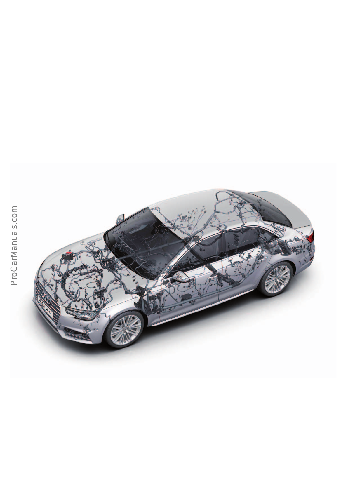
The AudiA4(type8W) is the second representative of the MLBevo
< Back
Forward >
Ξ Contents
(Modular Longitudinal Platform evolution) after the
AudiQ7(type4M). A fully equipped AudiA4(type8W) has around
90control units on board, many of which exchange data with one
another. Such close co-operation would not be possible without an
entirely new electronics architecture compared with the
AudiA4(type8K) – especially when it comes to the driver assistance systems.
The new FlexRay bus system in the AudiA4 networks multiple
control units and ensures that data is transmitted extremely
quickly and securely. The key components are the engine, the
automatic gearbox, the central suspension control unit, the Electronic Stability Control (ESC) system, the power steering control
unit, the Stop&Go adaptivecruisecontrol system including trac
jam assist, the video camera and the airbag control unit which
manages the safety systems.
There are further data networks in addition to the FlexRay bus.
CAN bus systems (CAN = controller area network) integrate the air
conditioning system and several assistance systems such as
Audisideassist and the surround cameras.
They also facilitate communication between the comfort/convenience control units, the infotainment modules and central display
and operating components such as the MMI and Audi virtual
cockpit.
So-called LIN buses (LIN = local interconnect network) complement the CAN buses by serving less complex subscriber systems
such as the interior lighting.
The Bang&OlufsenSoundSystem with 3D sound uses a MOST bus
(MOST = media oriented systems transport). As in other Audi
models, the AudiA4 now also has aluminium high-current wires
with diameters of 16mm2, 35mm2 and 50mm2.
However, the AudiA4 is the first Audi to use aluminium wires with
diameters of 2.5mm2, 4mm2 and 6mm2. Thanks to these modifications, the electronics in the new Audi mid-range models contribute to a lightweight design. The weight of the vehicle in this area
has been reduced by 6 kg compared with the previous model.
Learning objectives of this self study programme:
Once you have completed this self study programme you will be
able to answer the following questions:
• Where are the fuse and relay panels located in the Audi A4?
• In what locations are electrical components fitted on the car?
• Which bus systems are used in the AudiA4?
• What are the tasks of the control units in the car?
646_002
• What are the versions of the exterior lighting, and how are
the individual light functions implemented?
• What are the changes with regard to headlight range adjustment and calibration of the Audi Matrix LED headlights?
2
Page 3

Contents
Voltage supply
Car battery ___________________________________________________________________________________________________________________________________________________ 4
Jump start terminal _________________________________________________________________________________________________________________________________________ 5
Supply structure _____________________________________________________________________________________________________________________________________________ 6
Fuses and relays _____________________________________________________________________________________________________________________________________________ 7
Aluminium wires ____________________________________________________________________________________________________________________________________________ 8
Networking
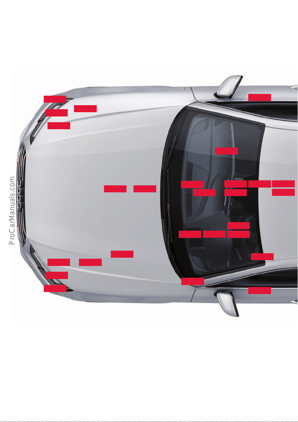
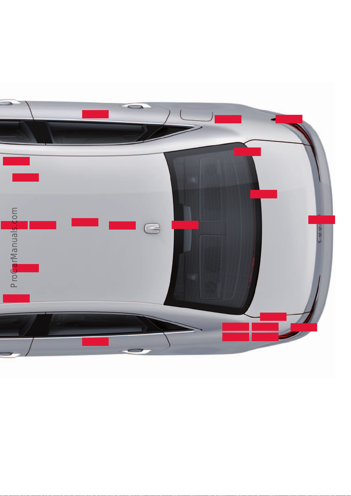
Installation locations of the control units _______________________________________________________________________________________________________________ 10
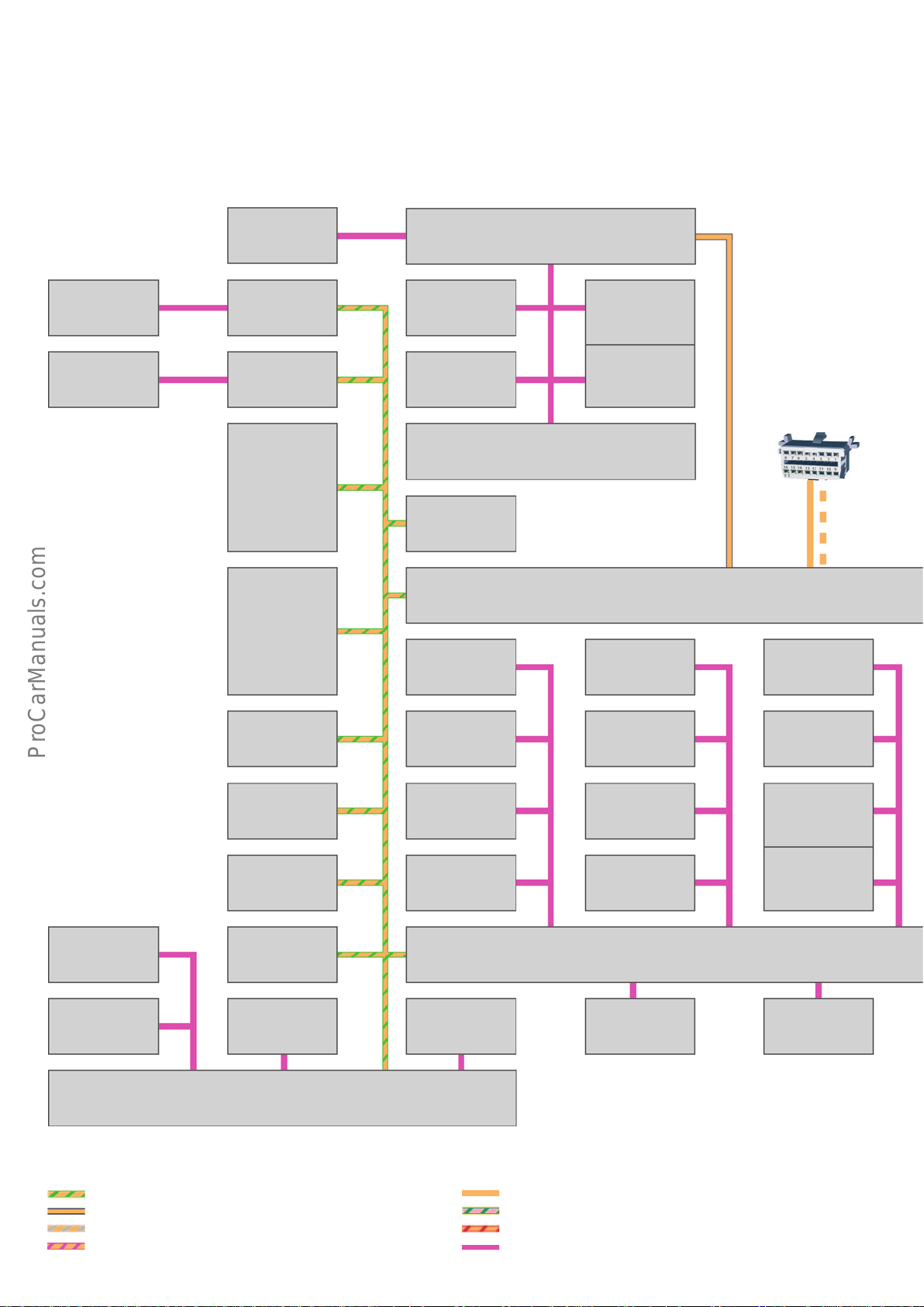
Topology ____________________________________________________________________________________________________________________________________________________12
Bus systems used on the AudiA4 ________________________________________________________________________________________________________________________14
Control units
Brief descriptions __________________________________________________________________________________________________________________________________________ 16
Exterior lighting
Headlight variants _________________________________________________________________________________________________________________________________________ 42
Xenon headlight ____________________________________________________________________________________________________________________________________________ 44
LED headlight _______________________________________________________________________________________________________________________________________________46
Audi Matrix LED headlight ________________________________________________________________________________________________________________________________48
Dynamic turn signal function _____________________________________________________________________________________________________________________________50
Tail lights ____________________________________________________________________________________________________________________________________________________51
High-level brake lights / number plate lights ___________________________________________________________________________________________________________54
Audi drive select
Functional characteristics _________________________________________________________________________________________________________________________________ 56
Displays and operation ____________________________________________________________________________________________________________________________________ 56
Audi drive select function _________________________________________________________________________________________________________________________________57
Functional features ________________________________________________________________________________________________________________________________________57
Vehicle electronics
Interior lighting ____________________________________________________________________________________________________________________________________________58
Overhead module __________________________________________________________________________________________________________________________________________ 62
Anti-theft alarm ____________________________________________________________________________________________________________________________________________ 63
Central locking _____________________________________________________________________________________________________________________________________________ 64
Sensor-controlled luggage compartment release ______________________________________________________________________________________________________ 66
Garage door opener (HomeLink) _________________________________________________________________________________________________________________________68
Head-up display ____________________________________________________________________________________________________________________________________________70
Appendix
Self study programmes ____________________________________________________________________________________________________________________________________71
new automotive components or new technologies.
It is not a repair manual! Figures are given for explanatory purposes only and refer to the data valid at the
time of preparation of the SSP.
This content is not updated.
For further information about maintenance and repair work, always refer to the current technical literature.
NoteThe self study programme teaches a basic understanding of the design and mode of operation of new models,
Reference
3
Page 4
Voltage supply
< Back
Forward >
Ξ Contents
Car battery
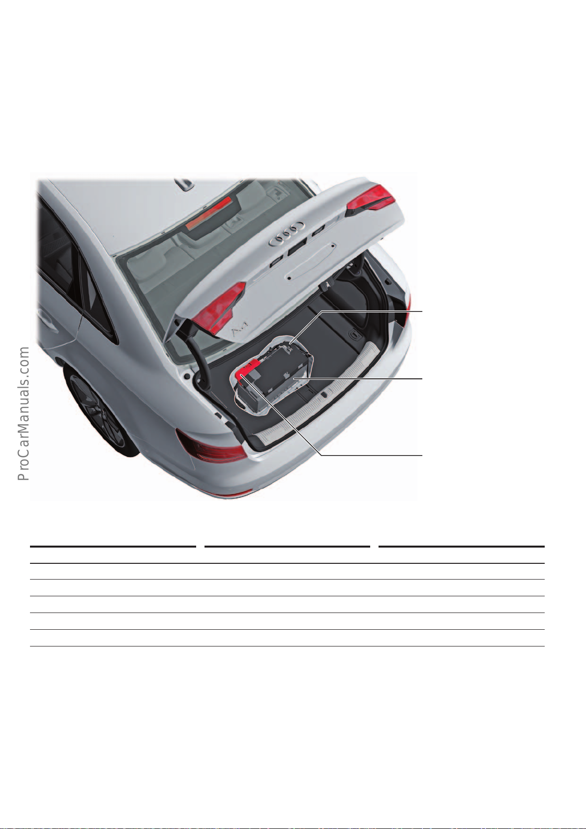
The car battery in the AudiA4(type 8W) is housed centrally in the
spare wheel well. The main fuse panel and the battery isolation
igniter N253 are located at the positive terminal of the car battery.
In the event of a crash, N253 disconnects the main battery lead.
The battery monitoring control unit J367 is located at the negative
terminal of the car battery. This control unit, also known as the
battery data module (BDM), combines with the earth lead to form
a unit.
Battery monitor control unit
J367
Battery
A
Main fuse panel and battery
isolation igniter
The following car batteries are used in the Audi A4:
Standard batteries EFB battery AGM car batteries
95 Ah/450 A 79 Ah/420 A 58 Ah/340 A
110 Ah/520 A 93 Ah/520 A 68 Ah/380 A
75 Ah/420 A
92 Ah/520 A
105 Ah/580 A
EFB battery
An EFB (Enhanced Flooded Battery) battery is a heavy-duty wet-cell
battery. The positive plate inside the car battery is coated with an
additional polyester scrim which provides the active mass of the
car battery with additional stability on the plate. The deep-cycle
resistance of these car batteries is higher than that of conventional
batteries. An EFB battery is charged in exactly the same way as a
standard car battery.
AGM car battery
AGM (Absorbent Glass Mat) car batteries have a glass microfibre
material inside in which the electrolyte is held. In addition to
having higher deep-cycle resistance, the AGM car battery is noted
for its leak-proof design. This is of course very important for
installation of the battery inside the car. When charging, it is
important to follow the charger's operating instructions and, if
required, to program the charger for AGM car batteries.
N253
646_081
4
Page 5
Jump start terminal
< Back
Forward >
Ξ Contents
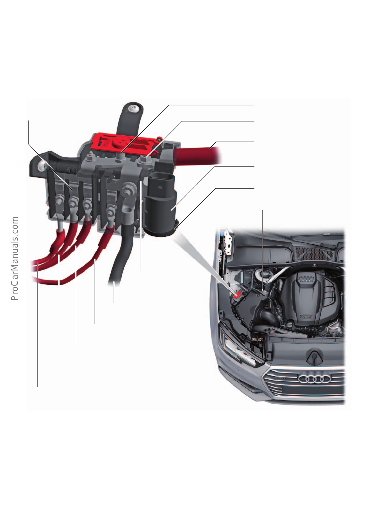
The jump start terminal (positive terminal) is located in the engine
bay on the right-hand side of the vehicle, adjacent to the air filter
box, under the red plastic cover. The earthing stud (negative
terminal) is connected directly to the body fore of the right suspension strut tower.
Distributor for term. 30
TV2
with fuses
These terminals should also be used for charging the car battery in
the showroom or for diagnostics in the workshop.
Jump start terminal
Terminal 30 supply
Distributor supply line
Interference suppression capacitor
C24
Sealing cap
Earthing stud
Distributor 2 for term. 30
TV22
Starter/alternator cable
Connection to radiator fan control unit J293
(4-cylinder engines)
Connection to automatic glow period control unit J179 or
secondary air pump relay J299
Connection to radiator fan control unit 2 J671
Connection to radiator fan control unit J293
The actual jump start terminal is on the terminal 30 distributor
TV22 to which the interference suppression capacitor C24 is also
attached. The red 70-mm2 cable supplies the distributor. The
3fuses on the distributor for term. 30 TV2 protect the radiator
fan, the glow plugs and the secondary air pump.
646_082
2
The black 70 mm
wire leads from distributor 2 for term. 30 TV22
to the starter. A further wire leads from here to the three-phase
ACmotor. In 4-cylinder models, the power supply of the radiator
fan control unit J293 is located adjacent to the wire leading to the
starter/3-phase AC motor.
5
Page 6
Supply structure
< Back
Forward >
Ξ Contents
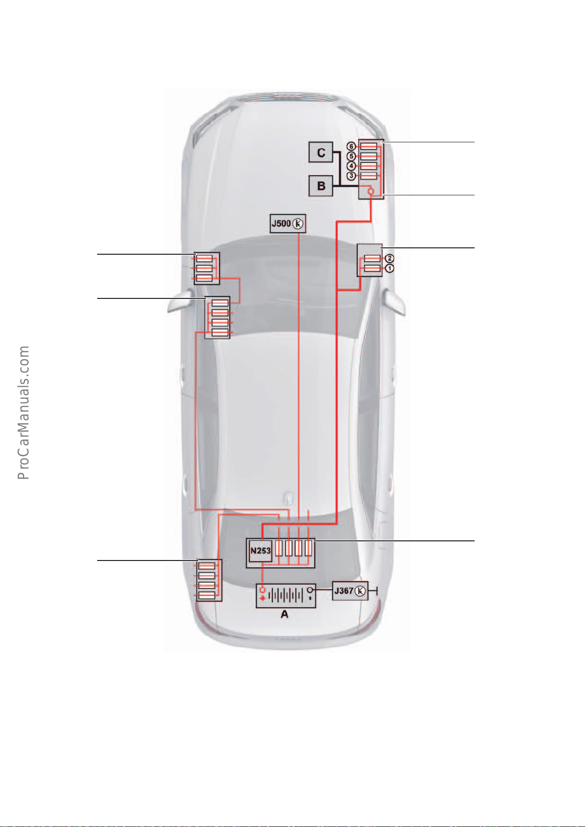
The following diagram summarises the supply structure of the
AudiA4. This is a schematic diagram.
SC
SB
For exact details of fuse assignment and the cable routing, please
refer to the applicable service literature.
TV22
TV2
TV1
SF
Key:
1 Connection to auxiliary air heater stage 1
2 Connection to auxiliary air heater stages 2+3
3 Connection to radiator fan control unit J293
(4-cylinder engines)
4 Connection to automatic glow period control unit J179 or
secondary air pump relay J299
5 Connection to radiator fan control unit 2 J671
6 Connection to radiator fan control unit J293
A Battery
B Starter motor
C Alternator
Main fuse panel
646_083
J367 Battery monitor control unit
J500 Power steering control unit
N253 Battery isolation igniter
SB Fuse panel B, on the footrest
SC Fuse panel C, on the dash panel
SF Fuse panel F, in luggage compartment on L/H side
TV1 Fuse and relay box at base of right A-post
TV2 Distributor for term. 30
TV22 Distributor 2 for term. 30
6
Page 7
Fuses and relays
< Back
Forward >
Ξ Contents
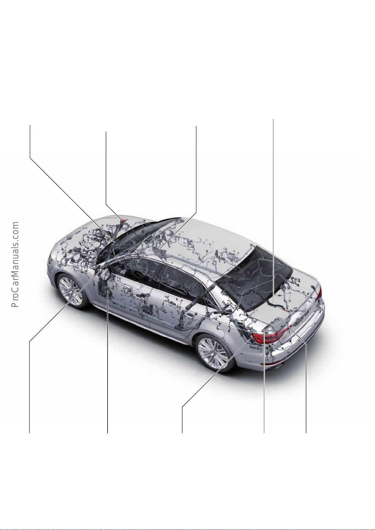
The fuses on the main fuse panel as well as distributors TV1 and
TV22 are labelled only "S" in the current flow diagram. This also
applies to other individual fuses distributed throughout the car.
Relay and fuse panel in
plenum chamber
Distributor for term. 30 TV2 and
distributor 2 for term. 30 TV22
with fuses
Fuses "SB", "SC" and "SF" can also be accessed by the driver on the
relevant fuse panels and therefore are also described in the
Owner's Manual.
Distributor for term. 30 TV1
with fuses
Main battery lead
Fuse panel C on the dash
panel, driver side.
The fuses here are labelled
"SC" in the current flow
diagram.
Fuse panel B on the driver
side footrest.
The fuses here are labelled
"SB" in the current flow
diagram.
Fuse panel F in the luggage
compartment, rear left.
The fuses here are labelled
"SF" in the current flow
diagram.
Main fuse panel at
positive terminal of
car battery
646_084
Battery monitor control
unit at negative terminal
of car battery
7
Page 8
Aluminium wires
< Back
Forward >
Ξ Contents
Main battery lead
Audi has been using aluminium electrical wires for some time now.
The AudiA4(type8W) makes no exception. The battery main lead
in the AudiA4 is made of aluminium, like the AudiA8(type4H)
where this was used for the first time. This lead begins at the main
fuse panel as a flexible round cable. On the right hand-side of the
luggage compartment well, it is welded onto a flexurally rigid
aluminium ribbon cable.
Wiring harness
A new feature of Audi vehicles, beginning with the
AudiA4(type8W), is the use of aluminium wires with diameters of
2.5mm2, 4mm2 and 6mm2 in certain areas of the wiring harness.
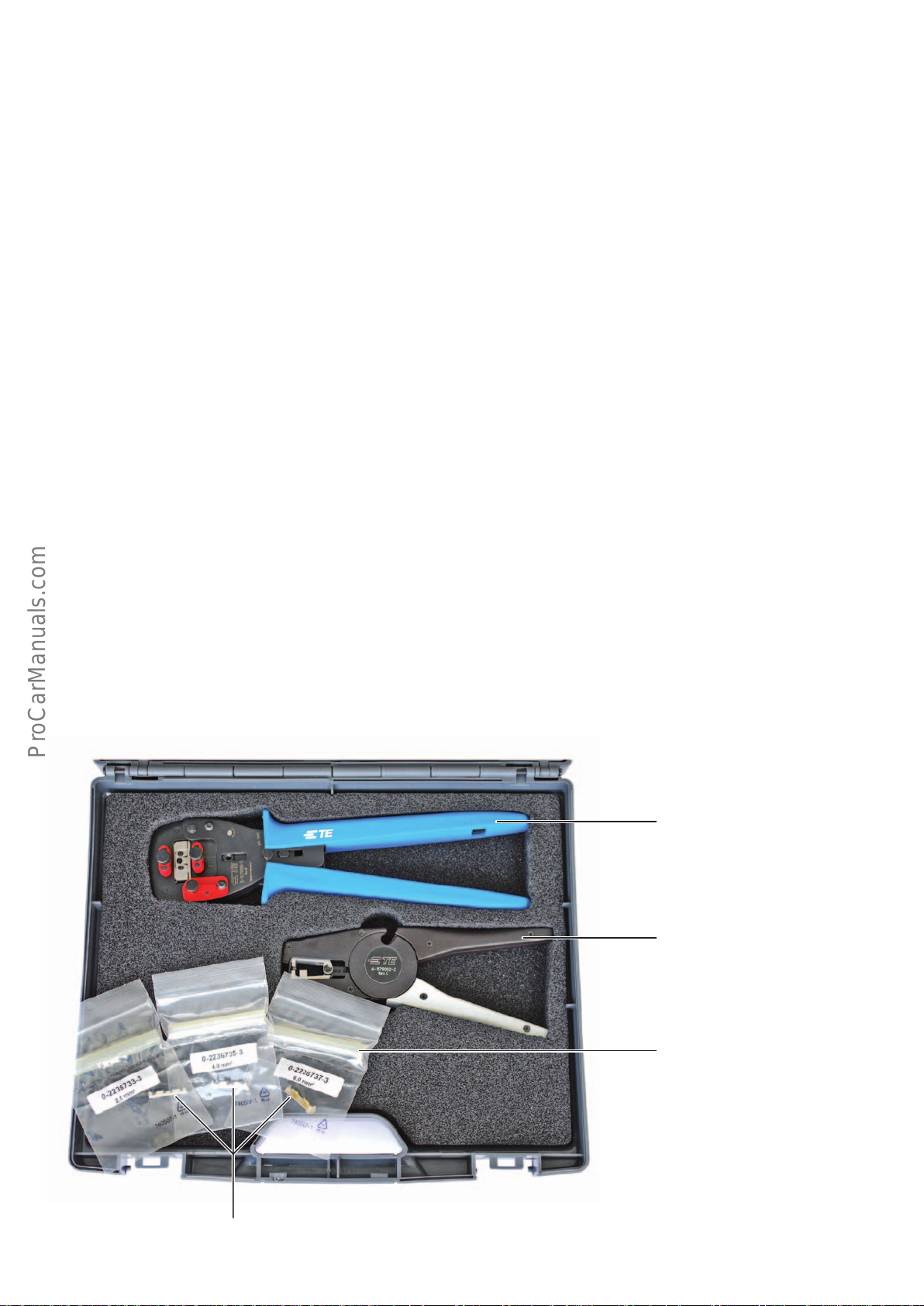
Repairing aluminium wires
A new tool was developed for the repair of aluminium wires –the
wires harness repair kit for aluminium wires VAS631001.
In addition to a crimping pliers, this repair kit includes a wire
stripper and a special crimp connector including heat shrink tubing
for wire diameters of 2.5mm2, 4mm2 and 6mm2.
This ribbon cable runs along the right-hand side of the vehicle
through the rear section of the vehicle and under the rear seat,
terminating in the heel panel area. Here it is welded onto a round
cable which continues along the inside of the right-hand sill and
through the engine bulkhead to the jump starting terminal in the
engine bay.
If faulty, the aluminium main battery lead can only be replaced
completely. There is no provision for repair work.
This helps save weight in the electrical system. Copper wires with
diameters from 1.5mm
areas in which wires are subject to movement, e.g. on the bonnet.
As before, copper wires can be repaired using the wiring harness
repair kit VAS1978B. Cut wires can be reconnected using crimp
connectors. Repair wires with industrial manufactured contacts are
also available.
2
to 6mm2 are also used, particularly in
Crimping pliers
Wire stripper
Heat shrink tubing
646_087
Crimp connector
8
Page 9
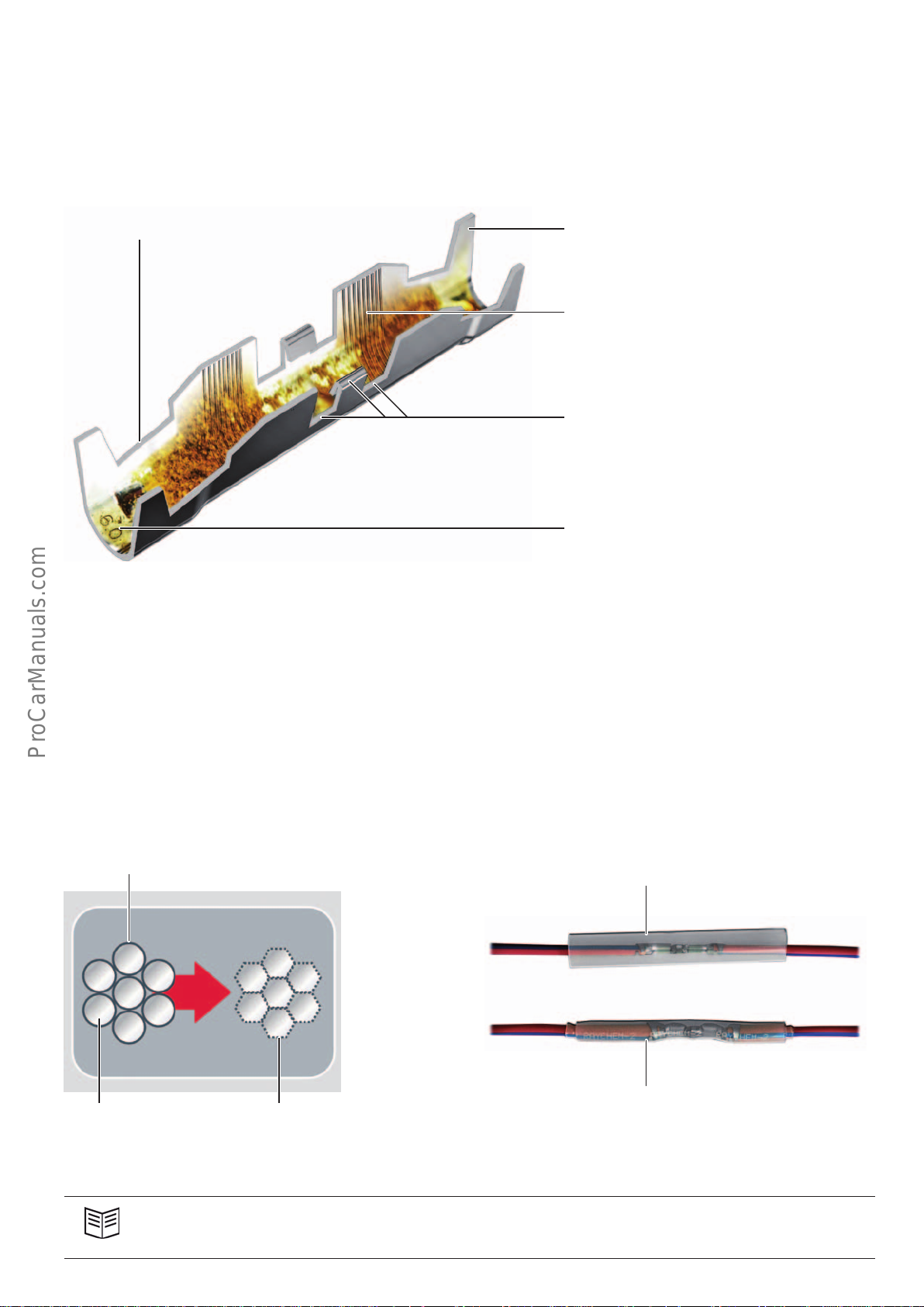
Special crimp connectors are used for the repair of aluminium
< Back
Forward >
Ξ Contents
wires. These connectors ensure strain resistant connection of the
aluminium wires. The supplied heat shrink tubing reliably protects
the joints against moisture.
Transition zone Insulation fitting
A cut aluminium wire can be reconnected using this crimp connector. If it is necessary to attach a new section of wires, the copper
repair wires from repair kit VAS 1978A can be used.
Wire crimping sleeve
with serrations and additive
Coding for wire diameter in crimping pliers
Challenges in repairing aluminium wires:
1. The crimp connector must provide a strain resistant connection.
To achieve a strain resistant connection with the aluminium wires,
the oxide layers on the individual strands of the aluminium wires
must be broken. This is achieved by the serrations in the crimp
connectors. These serrations are also coated with an additive to
provide better corrosion protection.
Oxide layer
Code for wire diameter
(both sides)
646_088
2. The joint must be sealed.
As copper repair wires are used, there is an aluminium wire on one
side of the connector and a copper wire on the other side. To
prevent electrochemical corrosion, the joint must be reliably
protected against corrosion. The heat shrink tubing supplied with
the crimp connector is used for this purpose.
Heat shrink tubing
Cable strand
646_089
Oxide layer broken by
serrations in connector
Heat shrink tubing
(heat shrunk)
Reference
For a detailed description of how to repair aluminium wires, please refer to the Workshop Manual.
646_090
9
Page 10
Networking
< Back
Forward >
Ξ Contents
Installation locations of the control units
Some of the control units shown in the overview are optional and/
or country-specific equipment.
For the sake of clarity, not all control units fitted in the vehicle can
be shown here.
J428
J364
J1023
A27
Refer to the current service literature for details of control unit
installation positions as well as instructions for installation and
removal.
J794
J217J500
J685
E87
J844
R242
J387
E380
J245
J587
J623
A31 J104
J1018
J850
Key:
A27 Right LED headlight power module 1
A31 Left LED headlight power module 1
E87 Front air conditioner/Climatronic operating and display unit
E265 Rear air conditioner/Climatronic operating and display unit
E380 Multimedia system operating unit
J104 ABS control unit
J136 Seat and steering column adjustment control unit with
memory
J217 Automatic gearbox control unit
J234 Airbag control unit
J245 Sliding sunroof control unit
J285 Instrument panel control unit
J764
J898
J519
J285
J527
J792
J386
J345 Trailer detector control unit
J364 Auxiliary heating control unit
J386 Driver side door control unit
J387 Front pass. side door control unit
J393 Central control unit for comfort/convenience system
J428 ACC control unit
J492 All-wheel drive control unit
J500 Power steering control unit
J519 Electrical system control unit
J521 Control unit for pass. seat adjustment with memory function
J525 Digital sound package control unit
J527 Steering column electronics control unit
J533 Data bus diagnostic interface
J587 Selector lever sensors control unit
10
Page 11
J649
< Back
Forward >
Ξ Contents
J521
J927
R78
J769
J880
J492
J234
J775
J136
J648
J605 Rear hatch control unit
J608 Control unit for special vehicles
J623 Engine control unit
J648 Control unit for rear left information display and operating
unit
J649 Control unit for rear right information display and operating
unit
J685 MMI display
J764 Electrical steering column lock control unit
J769 Audi lane assist control unit
J770 Audi lane assist control unit 2
J772 Rear-view camera system control unit
J775 Suspension control unit
J792 Control unit for active steering
E265
J926
J533
J605
J525
J928
J608
J345
J393
J770
J772
J794 Information electronics control unit 1
J844 Main beam assist control unit
J850 ACC control unit 2
J880 Reducing agent metering system control unit
J898 Control unit for windscreen projection J898 (head-up display)
J926 Door control unit, rear driver side
J927 Door control unit, rear pass. side
J928 Surround camera control unit
J1018 Control unit for light control, left
J1018 Control unit for light control, right
R78 TV tuner
R242 Front camera for driver assistance systems
646_010
11
Page 12
Topology
< Back
Forward >
Ξ Contents
The topology shows all control units with connectivity to the bus
systems.
Door control unit,
rear driver side
J926
Door control unit,
rear pass. side
J927
Flap control control
motors
1 –15
Driver side door
control unit
J386
Front pass. side
door control unit
J387
Seat and steering
column adjustment
control unit with
memory function
J136
Front air conditioner/Climatronic operating and display
unit
E87
Fresh air blower
control unit
J126
High pressure
sender
G65
Rear air conditioner/Climatronic operating and display
unit
E265
Electronic steering
column lock
control unit
J764
Some of the control units shown here are optional or countryspecific equipment or are scheduled for rollout at a later date.
Humidity sensor in
fresh air intake
duct
G657
Air quality sensor
G238
Diagnostic port
Front pass. seat
adjustment control
unit with memory
J521
Special vehicle
control unit
J608
Sliding sunroof
control unit
J245
Rear hatch
control unit
J605
Heated windscreen
control unit
J505
Anti-theft alarm
sensor
G578
Trailer detector
control unit
J345
Alarm horn
H12
Data bus diagnostic interface
J533
Seat back fan 1,
front left
V512
Seat cushion fan 1,
front left
V514
Seat back fan 1,
front right
V516
Seat cushion fan 1,
front right
V518
Electrical system control unit
J519
Rear hatch
power opening
control unit
J938
Garage door
operating unit
E284
Garage door opener
control unit
J530
Automatic anti dazzle rear view mirror
Y7
Roof electronics
control unit
J528
Interior light
module
Light switch
E1
Wiper motor
control unit
J400
Rain and light
detector sensor
G397
Humidity sensor
G355
Interior light
module
Central control unit for comfort/convenience system
J393
Key:
Convenience CAN
Hybrid CAN
Extended CAN
Infotainment CAN
12
Diagnostics CAN
FlexRay
Modular Infotainment Platform (MIB) CAN
LIN bus
Page 13
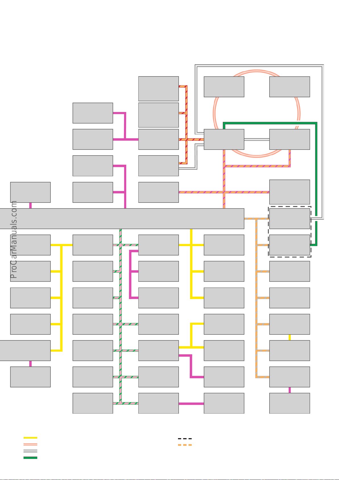
For presentation reasons, the FlexRay topology does not mirror the
< Back
Forward >
Ξ Contents
actual configuration of the control units. This also applies to the
control units connected to the MOST bus.
Multifunction
steering wheel
control unit
J453
L/H control unit for
light control
J1018
Driver side volume
control
E67
Multimedia system
key module
E817
Battery monitor
control unit
J367
Alternator
C
Front camera for
driver assistance
systems
R242
Control unit for
rear left information display and
operating unit
J648
Control unit for
rear right information display and
operating unit
J649
Multimedia system
operating unit
E380
MMI display
J685
Selector lever sensors control unit
J587
Engine control unit
J623
Digital sound
package
control unit
J525
Information
electronics
control unit1
J794
sender
NO
x
control unit
J583
TV tuner
R78
Control unit in dash
panel insert
J285
Control unit for
windscreen
projection
(head-up display)
J898
Surround camera
control unit
J928
or
Rear-view camera
system control unit
J772
R/H control unit for
light control
J1023
ABS control unit
J104
Left LED headlight
power module1
A31
Right LED headlight
power module1
A27
Operating unit 1 for
drive and comfort/
convenience functions E791
Power steering
control unit
J500
Suspension control
unit
J775
Steering column
electronics
control unit
J527
ACC control unit
J428
All-wheel drive
control unit
J492
Radiator louvre
control motor
V544
Radiator louvre
control motor 2
V550
Active steering
control unit
J792
Airbag
control unit
J234
ACC control unit 2
J850
Automatic gearbox
control unit
J217
NO
sender
x
control unit 2
J881
Particulate sensor
G784
Front left seat
belt tensioner
control unit
J854
Front right seat
belt tensioner
control unit
J855
Seat occupancy
recognition
control unit
J706
Electrical pump2
for gearbox
V553
Reducing agent
metering system
control unit
J880
Main beam assist
control unit
J844
Audi side assist
control unit
J769
Audi side assist
control unit 2
J770
Auxiliary heating
control unit
J364
Remote control
receiver for auxiliary heating
R64
646_003
Sub-bus systems
MOST bus
LVDS
FBAS
"OR" configuration
Ethernet port for diagnose interface VAS6154
13
Page 14
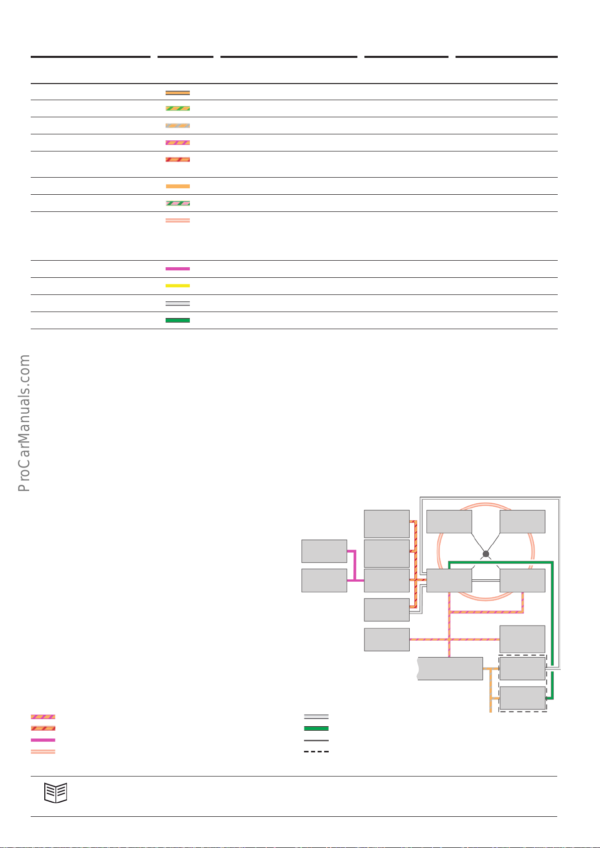
Bus systems used on the AudiA4
< Back
Forward >
Ξ Contents
Bus system Cable
colour
Conguration Max. data
transfer rate
Property
Hybrid CAN Electrical two-wire bus system 500kbit/s not single wire capable
Convenience CAN Electrical two-wire bus system 500kbit/s not single wire capable
Extended CAN Electrical two-wire bus system 500kbit/s not single wire capable
Infotainment CAN Electrical two-wire bus system 500kbit/s not single wire capable
Modular Infotainment
Electrical two-wire bus system 500kbit/s not single wire capable
Platform (MIB) CAN
Diagnostics CAN Electrical two-wire bus system 500kbit/s not single wire capable
FlexRay Electrical two-wire bus system 10Mbit/s not single wire capable
MOST bus Fibre-optic bus system 150Mbit/s Ring structure:
an open circuit will
result in total system
failure
LIN bus Electrical single-wire bus system 20kbit/s single wire capable
Sub-bus system Electrical two-wire bus system 500kbit/s not single wire capable
LVDS Electrical two-wire bus system approx. 200 Mbit/s not single wire capable
FBAS Electrical single-wire bus system approx. 80 Mbit/s single wire capable
The network diagram on page12 provides a schematic overview of
the communication paths between the control units in the Audi
A4. As a further member of the MLBevo family, the
AudiA4(type8W) cannot deny its close anity to the
AudiQ7(type4M) in the area of control unit networking. The bus
systems used in the AudiA4 are identical to those of the
AudiQ7(type4M).
Infotainment topology
In the AudiA4 up to 4control units are integrated in the MOST ring
in the following order:
• Information electronics control unit 1 J794
• Control unit in dash panel insert J285
• TV tuner R78
• Digital sound package control unit J525
If we compare this with the AudiQ7(type4M), the dierence is
that the DVD changer is absent from the MOST ring in the Audi A4.
Volume control E67 is configured as the LIN slave on the control
panel E380. In models with manual gearbox, the operator control
module for multimedia system E817 is additionally connected.
Control units J648 and J649 have been added to the MIB CAN and
will be also be featured in the AudiQ7(type4M) after the launch
of the AudiA4.
Key:
Infotainment CAN
Modular Infotainment Platform (MIB) CAN
LIN bus
MOST bus
If we compare the AudiA4(type8W) with the AudiA4(Typ8K),
new features in the area of data transmission are the FlexRay,
MOST150 and LVDS buses.
In spite of the many similarities with the AudiQ7(type4M), there
are a few dierences that are not exclusively equipment-specific.
For this reason, the topologies in the areas of infotainment and
FlexRay are described below.
R78
J285
J898J587
or
J772
646_051
E67
E817
LVDS
J648
J649
E380
J685
J525
J794
J533 J928
FBAS
Ring break diagnostics line
"OR" configuration
Reference
For further information and general descriptions of the MOST150 and FlexRay buses, refer to Self Study Programme634
"AudiQ7 (type4M) Onboard Power Supply and Networking".
14
Page 15
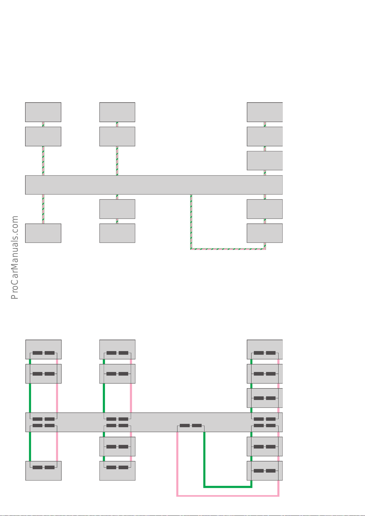
FlexRay topology
< Back
Forward >
Ξ Contents
The data bus diagnostic interface J533 is the controller for the
FlexRay bus. All FlexRay control units are connected to J533 via
various branches. In this configuration J533 is referred to as the
"active hub" or "active node". If only one control unit is connected
to a branch, this is referred to as a "point to point" connection.
ABS
control unit
J104
Engine
control unit
J623
Data bus diagnostic interface
J533
Branch4
Power steering
control unit
J500
Automatic gearbox control unit
J217
ACC
control unit2
J850
A configuration in which more than one control unit is connected
to a branch is known as a "daisy chain connection".
In the AudiA4 six branches are used: branches 1–5 and branch 8.
The pins of branches 6 and 7 are reserved in the current version of
J533, but are still not assigned.
The following figure is a schematic diagram showing how the
control units are connected.
Steering column
electronics
control unit
J527
Front camera for
driver assistance
systems
R242
Suspension
control unit
J775
Branch3Branch2Branch1
Branch8Branch5
Active steering
control unit
J792
Airbag
control unit
J234
ACC control unit
J428
The next figure shows the actual situation. In configuring of the
control units, a distinction is made between the bus positive cable
(pink) and the bus negative cable (green).
Two resistors each having a resistance of 47Ω (94Ω in total) are
always connected at the beginning and end of a branch. Each of
the so-called "centre control units" has two resistors with a resist-
ance of 1.3Ω, i.e. 2.6 Ω in total.
J104
1.3kΩ 1.3kΩ
J500
47Ω47Ω47Ω47Ω 47Ω47Ω
J217
1.3kΩ 1.3kΩ
All-wheel drive
control unit
J492
646_052
A control unit from the vehicle's standard specification is always
connected at the end of a branch. This ensures that there is a
resistance of 94 Ω at the end of each branch. Two optional control
units, which are integrated in other models as "centre control
units", are connected to branch 8 in the AudiA4. The FlexRay line
is, therefore, routed back to the data bus diagnostic interface
J533. The resistance here is 94 Ω - the value required for the
termination of branch 8.
J527
R242J623
1.3kΩ 1.3kΩ
J775
1.3kΩ 1.3kΩ
47Ω 47Ω
47Ω 47Ω
J533
Branch4
47Ω
47Ω 47Ω 47Ω
47Ω 47Ω
47Ω 47Ω 47Ω 47Ω
1.3kΩ 1.3kΩ
J850
J428 J492J234
Branch3Branch2Branch1
47Ω 47Ω
47Ω 47Ω
Branch8Branch5
1.3kΩ 1.3kΩ
J792
1.3kΩ 1.3kΩ
646_053
15
Page 16
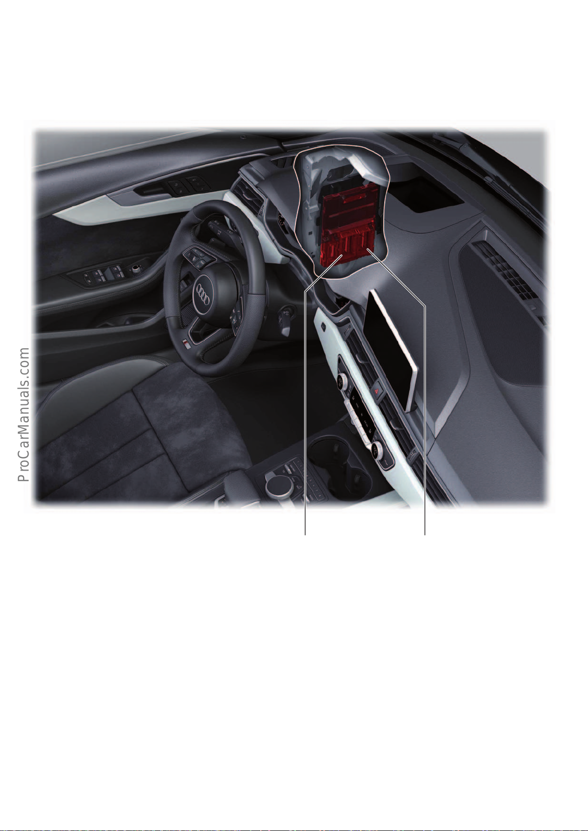
Control units
< Back
Forward >
Ξ Contents
Brief descriptions
Electrical system control unit
Connector C (54-pin)
to cockpit wiring harness
646_012
Connectors A and B (each 73-pin)
to vehicle / engine bay
16
Page 17

Designation Electrical system control unit J519 /
< Back
Forward >
Ξ Contents
also referred to as BCM1 (Body Control Module 1)
Equipment Always fitted
Installation location On A post, L/H side, above bonnet release lever
(installation location is always on the L/H side, even in RHD models)
Tasks Exterior lighting master
Interior lighting master
Diagnostic gateway for the light control units
A/C functions
• Activation of seat heater and front seat ventilation
• Activation of air conditioning compressor without regulating valve N280 and solenoid cou-
pling for air conditioning system N25
Integration functions
• Parking
• Parking aid
• Park assist steering
• Activation of front and rear acoustic signal generators
• Ambient lighting
• Activation and supply of LIN interior light modules
• Headlight range adjustment
• Calculation of headlight range adjustment
• Activation of headlight range adjustment via the left and right control units for light
control J1018 and J1023.
• Read-in of the signals from the inclination sensor via the CAN line
Other functions
• Reading (senders/sensors/switches)
• Ambient temperature
• New engine coolant, windscreen washer fluid, brake fluid
• Brake pad wear
• Bonnet contact
• Seater heater temperature
• Activation (actuators/control elements)
• Relay for sockets
• Signal horn
• Headlight washer system
• Windscreen washer pump (dual pump)
• Heating the windscreen washer jets
Diagnostic address 09
• Seat heater, front
Data bus communication • Convenience CAN subscribers
• J519 is the LIN master for
• LIN 1: Light switch E1, wiper motor control unit J400, combined sensor – rain and light
detection sensor G397 and humidity sensor G355
• LIN 2: Garage door operating unitE284, garage door operation control unitJ530, automatic anti dazzle rear view mirror Y7, roof electronics control unitJ528
• LIN 3: Front left seat back fan 1 V512, front left seat cushion fan V514, front right seat
back fan 1 V516, front right seat cushion fan V518
• LIN 4: Operating unit 1 for drive and comfort/convenience functions E791
• LIN 5: Interior light module
• LIN 6: Interior light module
• Communicates via a sub-bus system with the L/H and R/H control units for light control
J1018 andJ1023 and left and right LED headlight power modules 1 A31 and A27
Special feature Fault finding notes:
J519 has duplicated pins at the LIN slave connection. For example, LIN1 is distributed to
3pins (A22, A23,C50), which, however, are connected internally within the control unit. This
means that the control units connected to pin A23 and C50 are also aected in the event of a
short circuit to positive or negative at pin A22 and vice versa.
17
Page 18
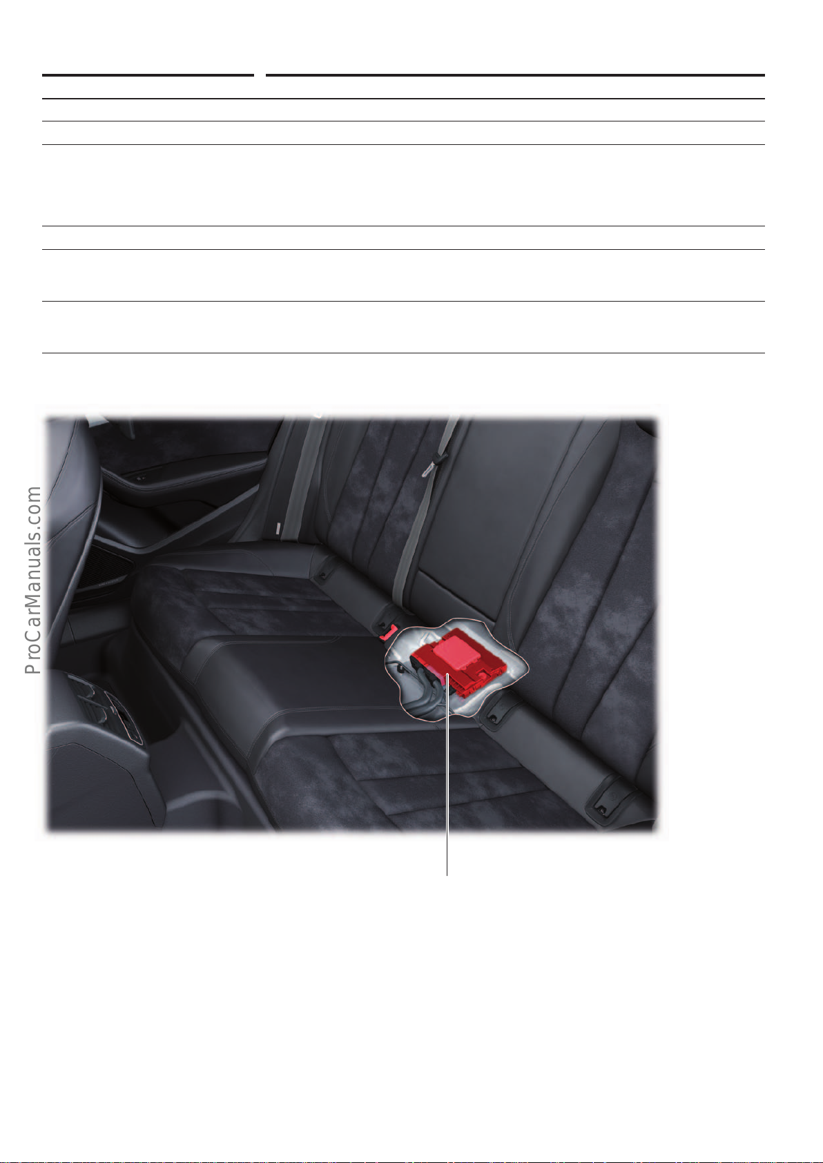
Gateway
< Back
Forward >
Ξ Contents
Designation Data bus diagnostic interface J533
Equipment Always fitted
Installation location Under the rear seat, on the floor pan
Tasks • Network system gateway
• Controller for FlexRay bus
• Diagnostic master
• Energy management control unit
• Interface for various connect services
Diagnostic address 19
Data bus communication • Hybrid CAN, convenience CAN, Infotainment CAN, CAN-Extended and FlexRay user
• LIN master of battery monitor control unit J367 and alternator C
• LIN master for multifunction steering wheel control unit J453
Special features • Not a user of the Modular Infotainment Platform (MIB) CAN
• Not a user of the MOST bus
• Additional variant as "connected gateway"
1)
646_011
Data bus diagnostic interface
J533
1)
Optional equipment
18
Page 19
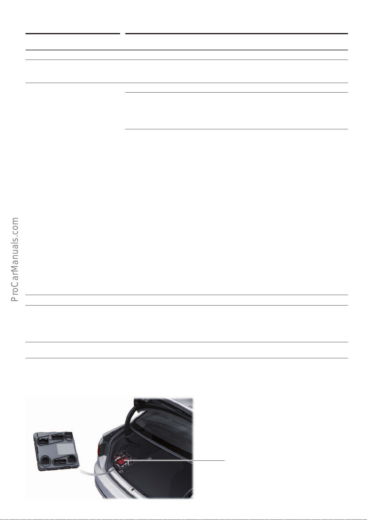
Central control unit for comfort/convenience system
< Back
Forward >
Ξ Contents
Designation Central control unit for comfort/convenience system J393 /
also referred to as BCM2 (Body Control Module 2)
Equipment Always fitted
Installation location In luggage compartment on L/H side, behind luggage compartment side trim, under fuse and
relay panel
(installation location is always on L/H side, even in RHD models)
Tasks Central locking system master
Integration functions
• Terminal management system
• Entry and start authorisation
• Immobiliser (master)
• Anti-theft alarm system
Other functions
• Reading (senders/sensors/switches)
• Brake light switch
• Ignition starter button
• P signal
• Soft touch button on rear hatch
• Rear hatch contacts (prelock and full lock)
• Rear window breakage sensor
• Capacitive sensors of door handles
• Entry and start authorisation aerials
• Fuel tank sender
• Inclination sensors for headlight range adjustment
• Hall eect sensor, rear roller blind
• Activation (actuators/control elements)
• Rear hatch lock motor
• Luggage compartment release
• Fuel tank flap lock
• Rear roller blind motor (Avant only)
• Terminal 15 relay
• Heated rear window relay
• Rear wiper motor (Avant only)
• Supply voltage, rear hatch power opening control unit
• Luggage compartment lights
• Rear lighting
Diagnostic address 46
Data bus communication • Convenience CAN subscribers
• J393 is the LIN master for:
• LIN 1: Control unit for windscreen heater J505, antitheft alarm system sensorG578
• LIN 2: Alarm horn H12
• LIN 3: Rear hatch power opening control unit J938
Special features • J393 is the immobiliser system master in the AudiA4
• Central locking aerial is integrated in the control unit PCB
Central control unit for comfort/convenience system
J393
646_013
19
Page 20
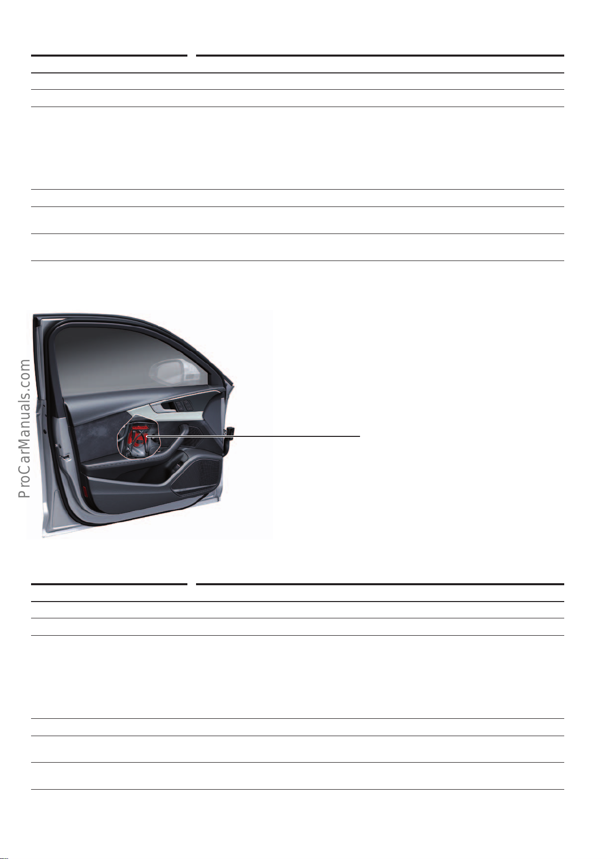
Door control unit
< Back
Forward >
Ξ Contents
Designation Driver side door control unit J386
Equipment Always fitted
Installation location In driver's door
Tasks Controlling the electrical and electronic components in and on the driver's door
• Reading (senders/sensors/switches)
• Switches/buttons, e.g. for window lifters, rear hatch release, electrical child lock
button, electrical door mirror, central locking, seat memory etc.
• Activation (actuators/control elements)
• Lights and components in and on the door trim, locking and safe motor, turn signals in
door mirror
Diagnostic address 42
Data bus communication • Convenience CAN subscribers
• LIN master for door control unit, rear driver side J926
Special feature The door control unit, rear driver side J926 has its own address code "BB" although it is a LIN
slave of J386.
Driver side door control unit
J386
Designation Front passenger side door control unit J387
Equipment Always fitted
Installation location In front passenger's door
Tasks Controlling the electrical and electronic components in and on the front passenger's door
• Reading (senders/sensors/switches)
• Switches/buttons, e.g. for window lifters, rear hatch release, electrical child lock
button, electrical door mirror, central locking, seat memory etc.
• Activation (actuators/control elements)
• Lights and components in and on the door trim, locking and safe motor, turn signals in
door mirror
Diagnostic address 52
646_014
Data bus communication • Convenience CAN subscribers
• LIN master for door control unit, rear passenger side J927
Special feature The door control unit, rear passenger side J927 has its own address code "BC" although it is a
LIN slave of J387.
20
Page 21
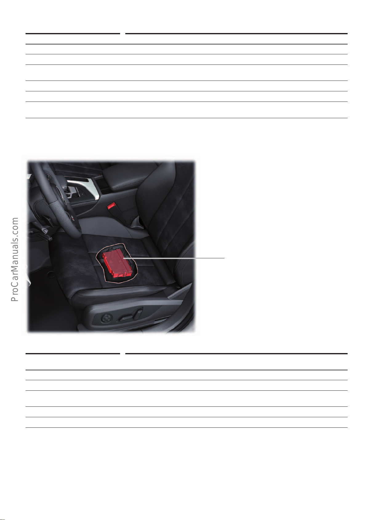
Seat adjustment
< Back
Forward >
Ξ Contents
Designation Seat and steering column adjustment control unit with memory J136
Equipment Optional equipment (PR no.: PV3)
Installation location Below the driver's seat
Tasks Activation (actuators/control elements)
• Seat adjustment (memory function)
Diagnostic address 36
Data bus communication Convenience CAN subscribers
Special feature Contrary to what the name of the control unit in the "mummy list" would suggest, an electri-
cal steering wheel lock is not available in the Audi A4.
Seat and steering column adjustment control unit
with memory function
J136
Designation Control unit for passenger seat adjustment with memory function
J521
Equipment Optional equipment (PR no.: PV3)
Installation location Below the front passenger seat (not shown)
Tasks Activation (actuators/control elements)
• Seat adjustment (memory function)
Diagnostic address 06
Data bus communication Convenience CAN subscribers
646_015
21
Page 22
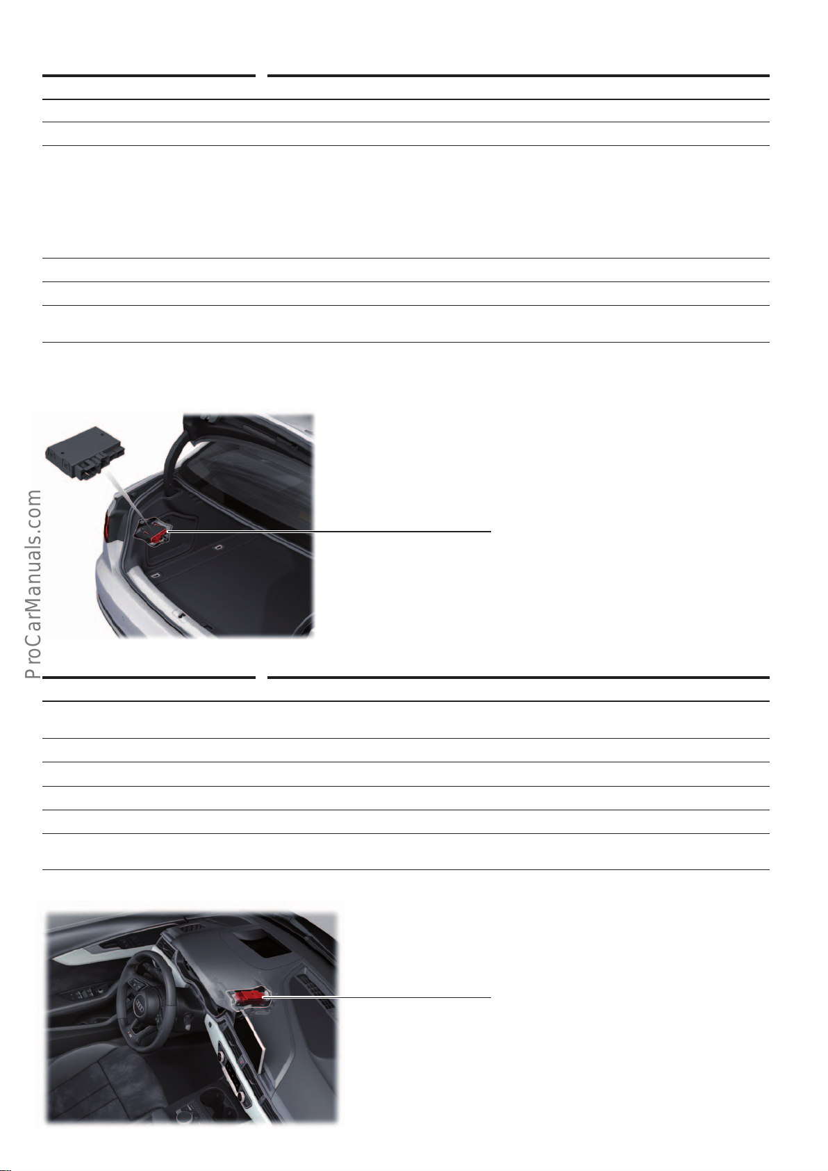
Trailer detector
< Back
Forward >
Ξ Contents
Designation Trailer detector control unit J345
Equipment Optional equipment (PR no.: 1D9)
Installation location In luggage compartment, L/H side, behind luggage compartment side trim
Tasks Interconnects the in-car electrics and the trailer electrics
• Reading (senders/sensors/switches)
• Brake light switch
• Tow bar release button
• Activation (actuators/control elements)
• Tow bar warning lamp
• Tow bar lowering motor
Diagnostic address 69
Data bus communication Convenience CAN subscribers
Special feature Although the tow bar can be unlocked via a switch in the left luggage compartment trim, it
must be moved into its end position by hand until it audibly engages.
Trailer detector control unit
J345
Steering column lock control unit
Designation Electronic steering column lock control unit J764
Equipment • Always installed in vehicles with a manual gearbox
• In the case of vehicles with an automatic gearbox, installation is country-dependent
Installation location On steering column
Task Locking and unlocking the steering column
Diagnostic address 2B
Data bus communication Convenience CAN subscribers
Special features • Immobiliser user
• Can be replaced separately from the steering column
646_016
Electronic steering column lock control unit
J764
646_017
22
Page 23
Sliding sunroof control unit
< Back
Forward >
Ξ Contents
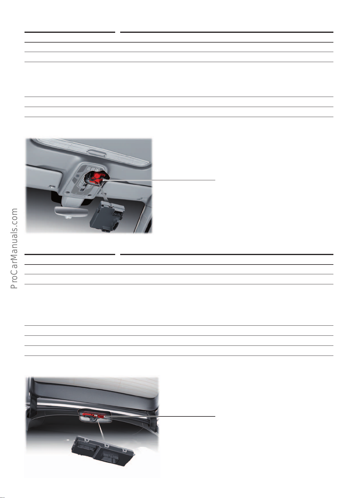
Designation Sliding sunroof control unit J245
Equipment Optional equipment (PR no.: 3FU)
Installation location On sliding sunroof frame at front
Tasks Controlling the functions of the panoramic glass sunroof
• Reading (senders/sensors/switches)
• Controller for sliding sunroof adjustment
• Activation (actuators/control elements)
• Motors for sliding sunroof V1 and sliding sunroof roller blindV260
Diagnostic address CA
Data bus communication Convenience CAN subscribers
Sliding sunroof control unit
J245
Rear hatch control unit
Designation Rear hatch control unit J605
Equipment For Avant only
Installation location On roof cross member, rear centre
Tasks Controlling the functions of the electrical rear hatch
• Reading (senders/sensors/switches)
• Button for closing the rear hatch
• Activation (actuators/control elements)
• Rear hatch drive motors
• Luggage compartment cover motor
Diagnostic address 6D
Data bus communication Convenience CAN subscribers
Special feature The rear hatch control unit activates the rear parking aid speaker.
1)
646_018
1)
Optional "electrical luggage compartment cover" (PR no.: PKC)
Rear hatch control unit
J605
646_019
23
Page 24
Interface control unit
< Back
Forward >
Ξ Contents
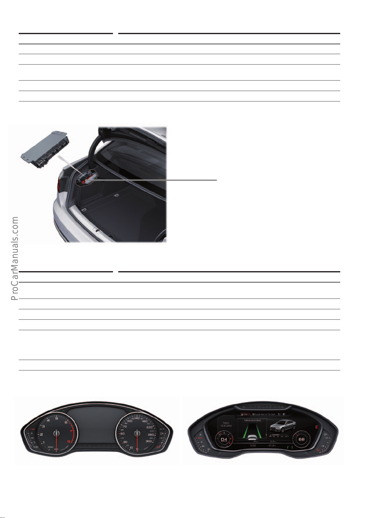
Designation Special vehicle control unit J608
Equipment Optional equipment (PR no.: e.g.: F4X paramedic version, F4G police version etc.)
Installation location In luggage compartment, L/H side, behind luggage compartment side trim
Task J608 serves as an interface between special installations, e.g.for paramedics, police, fire
service etc., and the vehicle electrics
Diagnostic address 3D
Data bus communication Convenience CAN subscribers
Special vehicle control unit
J608
Instrument cluster
Designation Control unit in dash panel insert J285
Equipment • Always fitted
Installation location In dash panel
Task Display of information relevant to the driver
Diagnostic address 17
Data bus communication • Infotainment CAN bus user
Special feature The instrument cluster in the AudiA4 is not integrated in the immobiliser.
• Optional Audivirtual cockpit (PR no.: 9S8)
• MOST subscriber
• Connected by LVDS bus to information electronics control unit 1 J794 (image transfer for
navigation display in instrument cluster).
646_085
24
Control unit in dash panel insert
J285
646_020
646_086
Control unit in dash panel insert
J285
(Audivitualcockpit)
Page 25
ACC adaptive cruise control
< Back
Forward >
Ξ Contents
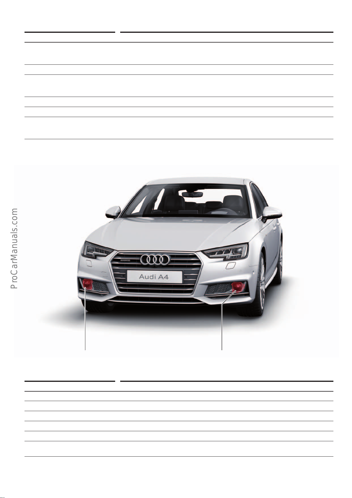
Designation ACC control unit J428
Equipment Optional equipment:
• ACC with Stop&Go including trac jam assist (PR no.: 8T8)
• ACC distance indicator (PR no.: 8T3)
Installation location On lock carrier, front right, behind front bumper cover
Tasks • Radar scanning of trac (distance and speed)
• Controlling speed and distance
• Distance display and distance warnings (only if ACC is deactivated)
Diagnostic address 13
Data bus communication FlexRay subscriber
Special features • ACC Stop&Go with integrated trac jam assistant
• Distance display and distance warning – display of distance in instrument cluster in seconds
• Function master for ACC control unit 2 J850
ACC control unit
J428
Designation ACC control unit 2 J850
Equipment Optional equipment
Installation location On lock carrier, front left, behind front bumper cover
Task Radar scanning of trac (distance and speed)
Diagnostic address 8B
Data bus communication FlexRay subscriber
Special feature ACC control unit 2 is a slave of the ACC control unit J428 and, based on its function, could also
be referred to as a sensor.
ACC control unit 2
J850
646_021
25
Page 26
Main beam assist
< Back
Forward >
Ξ Contents
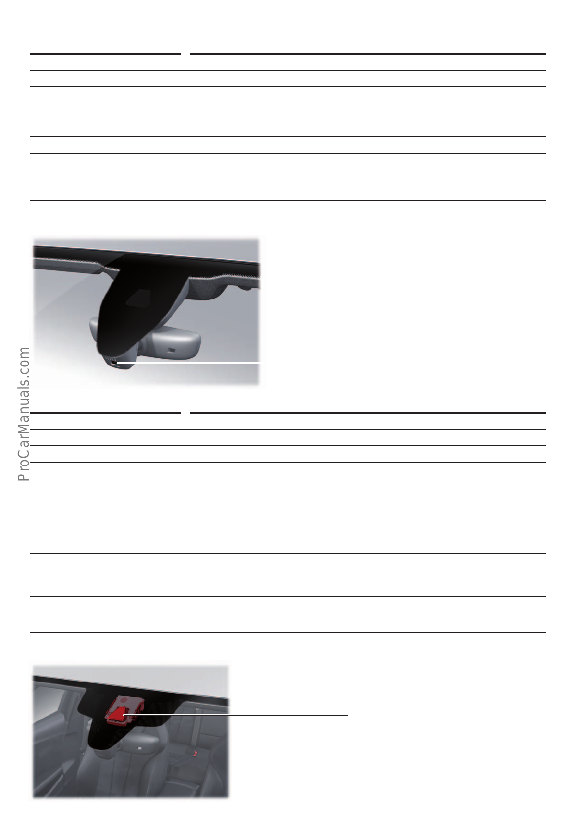
Designation Main beam assist control unit J844
Equipment Optional equipment (PR no.: 8G1)
Installation location In rear view mirror
Task Automatic activation and deactivation of main beam in response to oncoming trac
Diagnostic address 20
Data bus communication Extended CAN subscriber
Special features • J844 can only change over the dipped/main beam headlights. The front camera for driver
assistance systems R242 is required for Audi matrixLED headlights.
• Only installed if the customer has ordered main beam assist without further assistance
systems, such as Audi active Lane Assist or trac sign recognition.
Main beam assist control unit
J844
Front camera
Designation Front camera for driver assistance systems R242
Equipment Optional equipment
Installation location On windscreen above base of rear view mirror
Tasks Imaging of trac, trac signs and lane markers for
Diagnostic address A5
Data bus communication • FlexRay subscriber
Special features • Forms a functional unit in combination with image processing control unit
• Audi active lane assist (lane departure warning system)
• Main beam assist
• Road sign recognition
• ACC Stop&Go
• Audi pre sense
• Evasion assist
• Matrix Beam headlight
• R242 is connected to the light control units via a sub-bus system.
• The Audi MatrixLED headlights are also calibrated using the front camera for driver assist-
ance systems R242.
646_022
Front camera for driver assistance systems
R242
646_023
26
Page 27
Automatic gearbox
< Back
Forward >
Ξ Contents
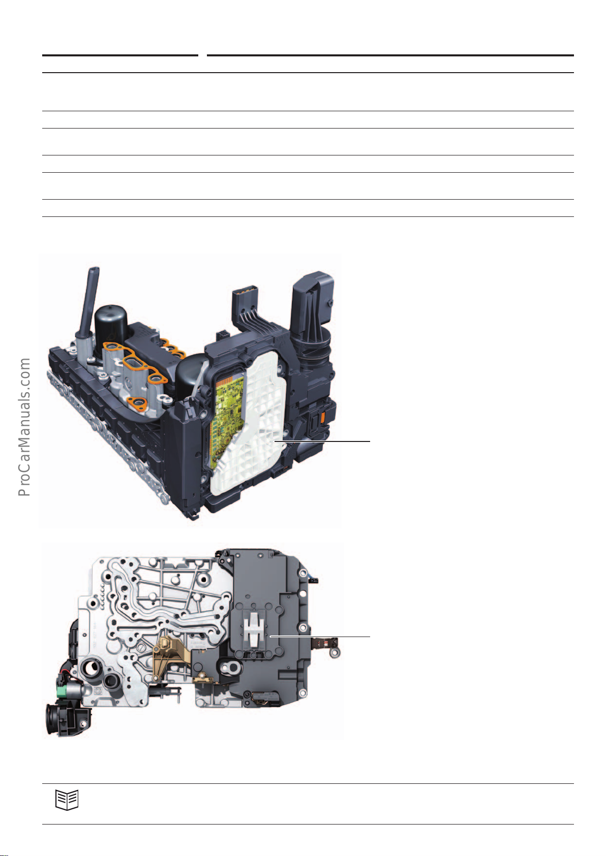
Designation Automatic gearbox control unit J217
Equipment Installed in combination with:
• 7-speed dual clutch gearbox 0CK/0CL – Stronic (PR no.: G1C/G1D)
• 8-speed automatic gearbox 0D5 – tiptronic (PR no.: G1G)
Installation location Component part of mechatronic unitJ743 of automatic gearbox
Task Controlling and monitoring the engagement and disengagement operations of the automatic
gearbox
Diagnostic address 02
Data bus communication • FlexRay subscriber
• LIN master for electrical pump2 for gearboxV553 (in conjunction with 7-speed Stronic)
Special feature Immobiliser user
Automatic gearbox control unit
J217
(7-speed dual clutch gearbox 0CK/0CL)
646_047
Automatic gearbox control unit
J217
(8-speed automatic gearbox 0D5)
646_024
Reference
For further information about the automatic gearboxes, refer to Self Study Programme644 "AudiA4 (type8W)".
27
Page 28
Selector mechanism
< Back
Forward >
Ξ Contents
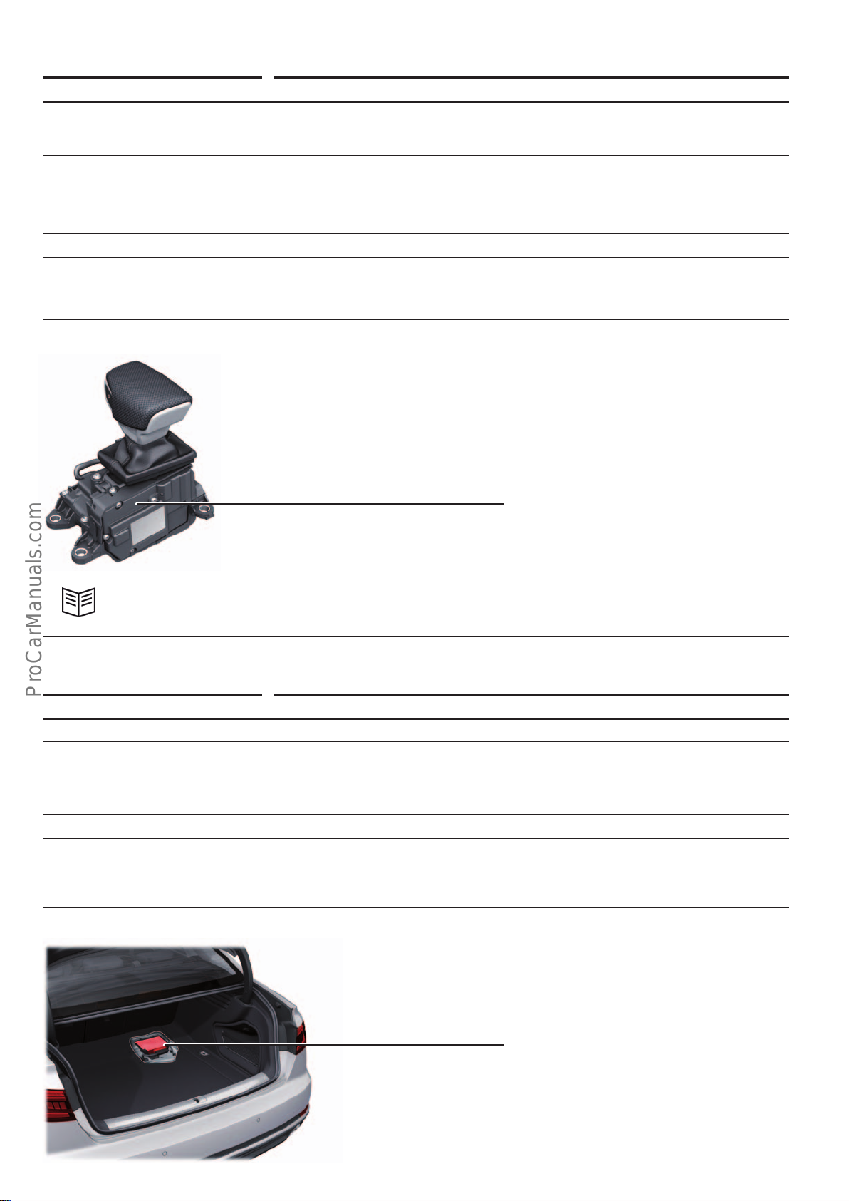
Designation Selector lever sensors control unit J587
Equipment Installed in combination with:
• 7-speed dual clutch gearbox 0CK/0CL – Stronic (PR no.: G1C/G1D)
• 8-speed automatic gearbox 0D5 – tiptronic (PR no.: G1G)
Installation location Within the selector mechanism
Tasks Operating the automatic gearbox, e.g. transmitting drive positions, controlling the mechani-
cal selector lever locks, transmitting selector lever tiptronic commands and resetting the
selector lever in the automatic gate.
Diagnostic address 81
Data bus communication Infotainment CAN bus user
Special features • J587 can only be replacded together with the selector mechanism.
• The selector mechanism is not mechanically connected to the automatic gearbox.
Selector lever sensors control unit
J587
Reference
For further information about the selector mechanism, refer to Self Study Programme644 "AudiA4 (type8W)".
Rear final drive 0D3–sport dierential
Designation All-wheel drive control unit J492
Equipment Optional equipment (PR no.: GH2)
Installation location In luggage compartment
Task Controls the torque of the sport dierential's multi-plate clutch
Diagnostic address 22
Data bus communication FlexRay subscriber
Special features • Special procedures must be followed when replacing the control unit.
• The driving dynamics control system is integrated in the suspension control unit J775, and
no longer in the all-wheel drive control unit J492. All that control unit J492 does is execute
the commands issued by J775.
646_025
All-wheel drive control unit
J492
646_026
28
Page 29
Steering column electronics
< Back
Forward >
Ξ Contents
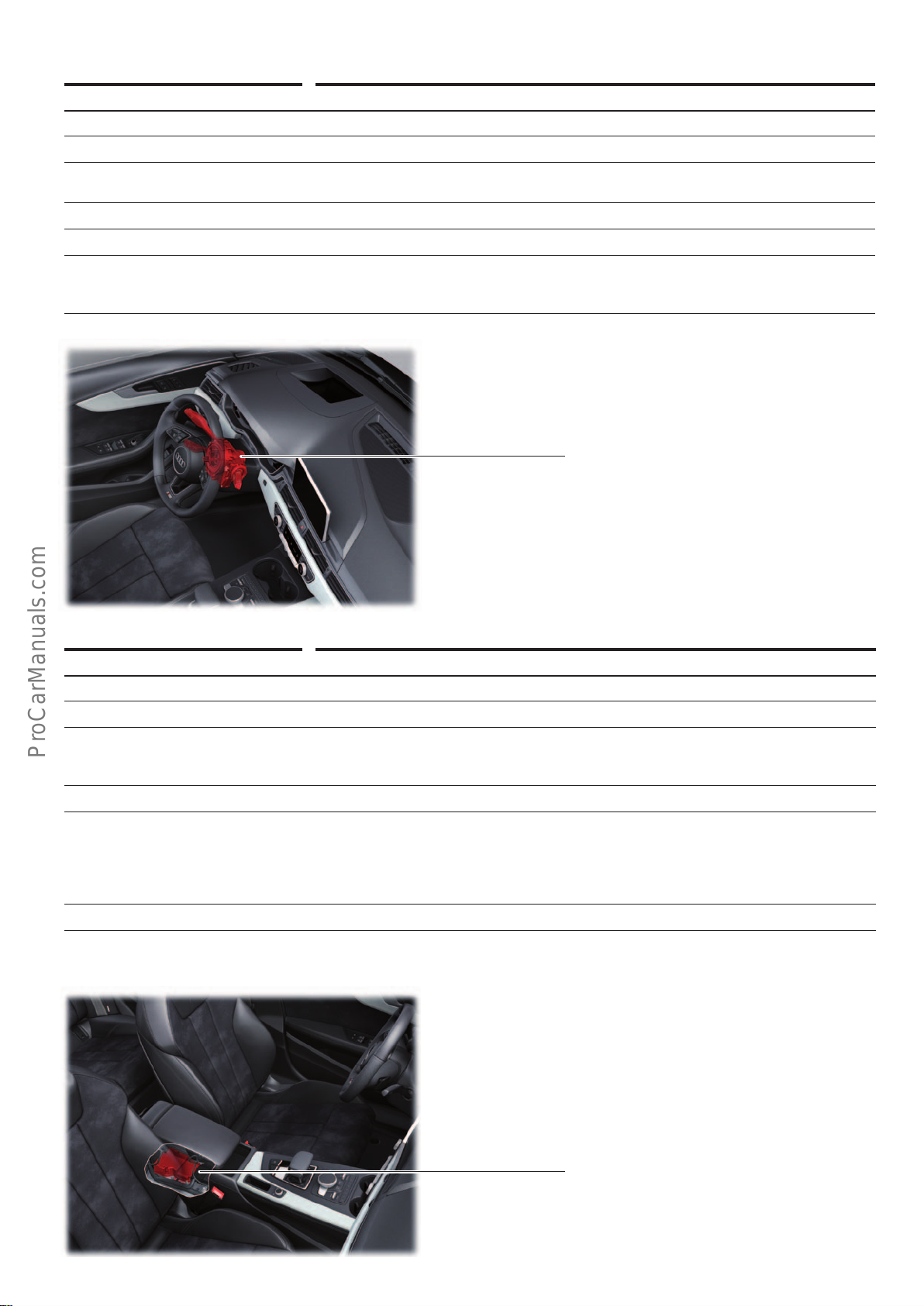
Designation Steering column electronics control unit J527
Equipment Always fitted
Installation location On steering column
Task Connects the steering column stalk and the electrical components in the steering wheel to the
vehicle's electronics.
Diagnostic address 16
Data bus communication FlexRay subscriber
Special feature In conjunction with the multifunction steering wheel, it transfers the LIN signals from the
data bus diagnostic interface J533 (master) to the multifunction steering wheel control unit
J453 (slave).
Steering column electronics control unit
J527
Airbag
Designation Airbag control unit J234
Equipment Always fitted
Installation location Under centre console, front, on centre tunnel
Tasks • Deployment of airbags, seat belt pretensioners and battery isolation igniter
Diagnostic address 15
Data bus communication • FlexRay subscriber
Special feature Inertial sensors for ESC
• Audi pre sense
• Deployment of the pedestrian protection system
• Is connected to the front left (J854) and front right (J855) seat belt pretensioner control
units via a sub-bus system.
• LIN master for seat occupancy recognition control unit J706 (for North American market
only)
646_027
Airbag control unit
J234
646_028
29
Page 30
Engine control unit
< Back
Forward >
Ξ Contents
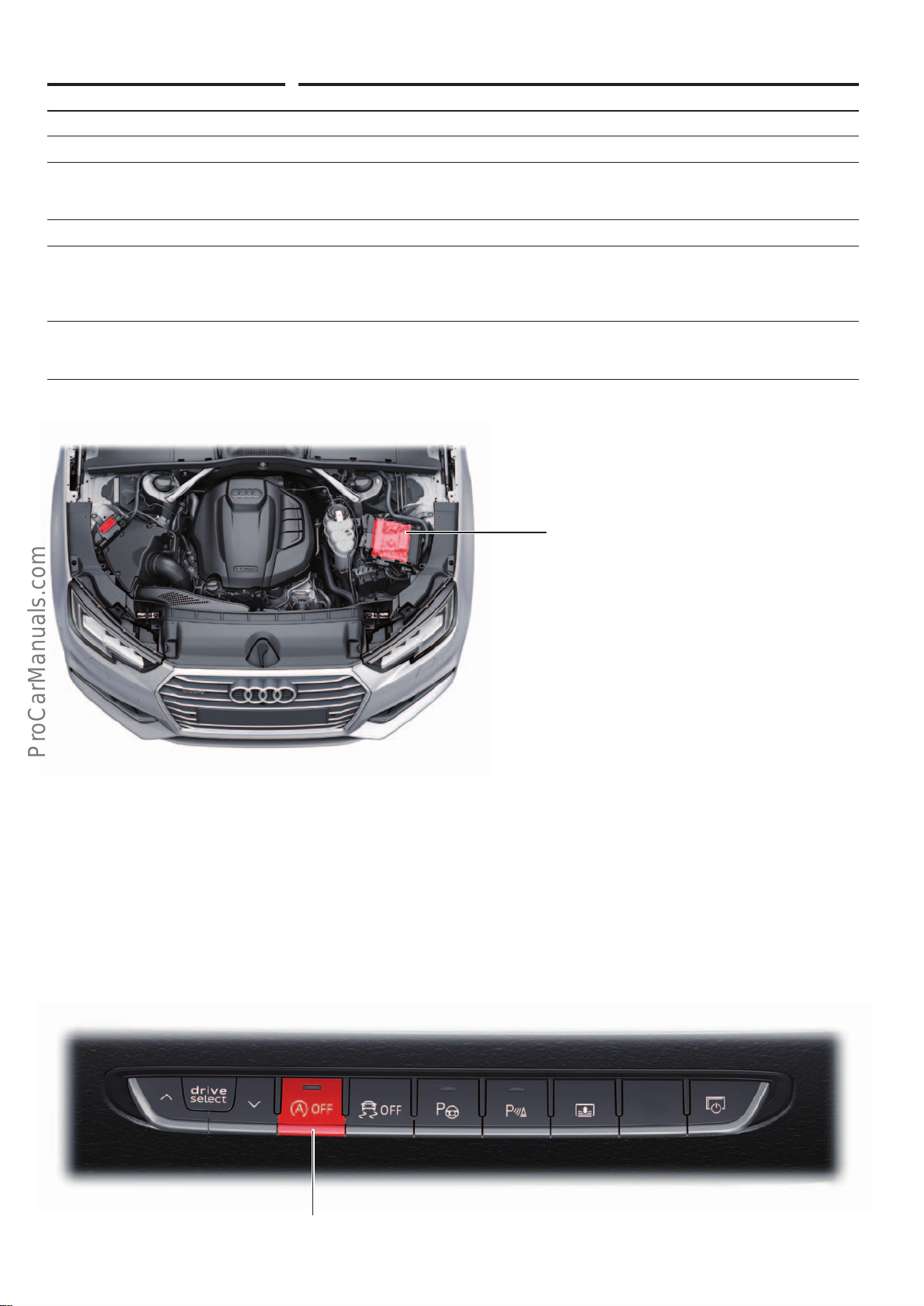
Designation Engine control unit J623
Equipment Always fitted
Installation location In engine bay, L/H side, in front of plenum chamber
Tasks • Controlling the engine characteristic
• Activation of starter relays J906 and J907
• Function master for start-stop system
Diagnostic address 01
Data bus communication • FlexRay subscriber
• J623 is connected to NO
system.
• LIN master for radiator lourvre control motors 1 and 2 V544 and V550
Special features • Immobiliser user
• Control unit with new plug-in connections. Has a total of 315 pins. New test adapter
VAS6606/23 for test box VAS6606
senders and the particulate sensor (diesel engine) via a sub-bus
x
Start-stop system
As with all Audi models with start-stop system, the engine control
unit J623 is the coordinator for the start-stop function in the
AudiA4.
The AudiA4(type8W) is equipped with a start-stop system in
Version2.0, which was first used in the AudiQ7(type4M).
Engine control unit
J623
646_030
For a history of the start-stop system and a detailed description of
Version2.0, refer to SSP634 "AudiQ7(type4M) Onboard Power
Supply and Networking".
Operating unit 1 for drive and comfort/convenience functions E791
646_080
Start-stop mode button
E693
30
Page 31
SCR system
< Back
Forward >
Ξ Contents
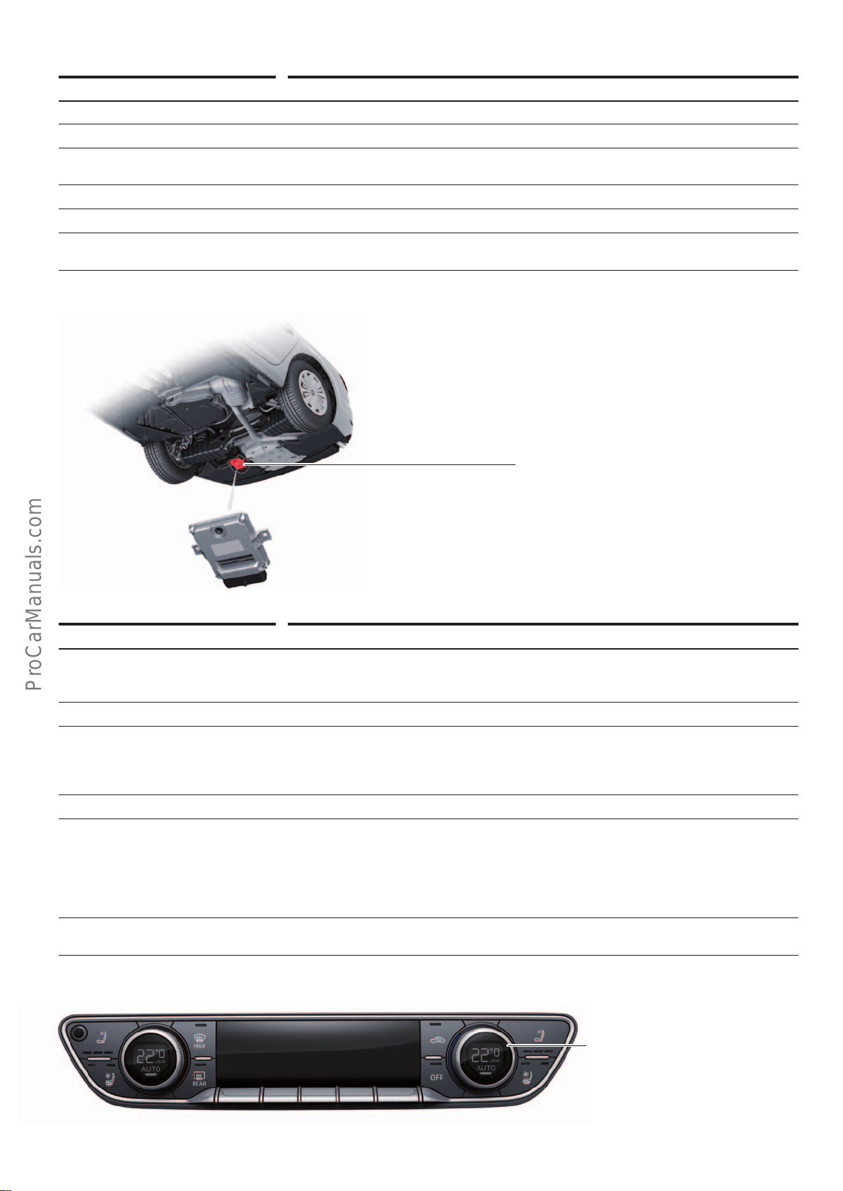
Designation Reducing agent metering system control unit J880
Equipment Always installed in diesel models
Installation location On the underside of the SCR tank
Task Controlling the injection of reduction agent for reduction of the nitrous oxides in the exhaust
gases
Diagnostic address AC
Data bus communication Extended CAN subscriber
Special feature The control unit is identical in all diesel models. The size of the reduction agent tank can vary:
standard SCR tank capaciity 12l; "extended range" SCR tank capacity 24l
Reducing agent metering system control unit
J880
1)
.
646_031
Front A/C control panel
Designation Front air conditioner/Climatronic operating and display unit E87
Equipment Always fitted
• Automatic air conditioning (PR no.: 9AK)
• Automatic air conditioning (PR no.: 9AQ)
Installation location In centre of dash panel
Tasks Controlling:
• Temperature
• Fan speed
• Air flow distribution
Diagnostic address 08
Data bus communication • Hybrid CAN user
• E87 is the LIN master for
• LIN 1: Control motors for flap activation 1–15
• LIN 2: Rear air conditioner/Climatronic operating and display unit E265, fresh air blower
control unit J126, humidity sensor in fresh air intake duct G657, air quality sensor
G238, high pressure sensor G65
Special feature Although the seat seating and seat ventilation switches are integrated in and read in by oper-
ating unit E87, the electrical system control unit J519 is responsible for their activation.
Front air conditioner/Climatronic operating
and display unit
E87
(figure shows deluxe automatic air conditioning system)
1)
Optional equipment
646_029
31
Page 32
Head-up display
< Back
Forward >
Ξ Contents
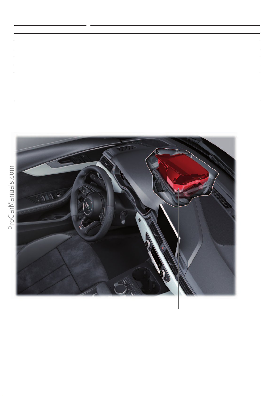
Designation Control unit for windscreen projection (head-up display) J898
Equipment Optional equipment (PR no.: KS1)
Installation location In dash panel, directly in front of instrument cluster
Task Controlling all optical, mechanical and electrical components of the head-up display
Diagnostic address 82
Data bus communication Infotainment CAN bus user
Special features • The control units can only be replaced complete with the other components of the head-up
display.
• To replace the head-up display, the windscreen must be removed.
• When replacing the windscreen, please note: the head-up display requires a special screen
(with wedge-shaped foil).
646_032
Control unit for windscreen projection (head-up display)
J898
32
Page 33
Rear-view camera
< Back
Forward >
Ξ Contents
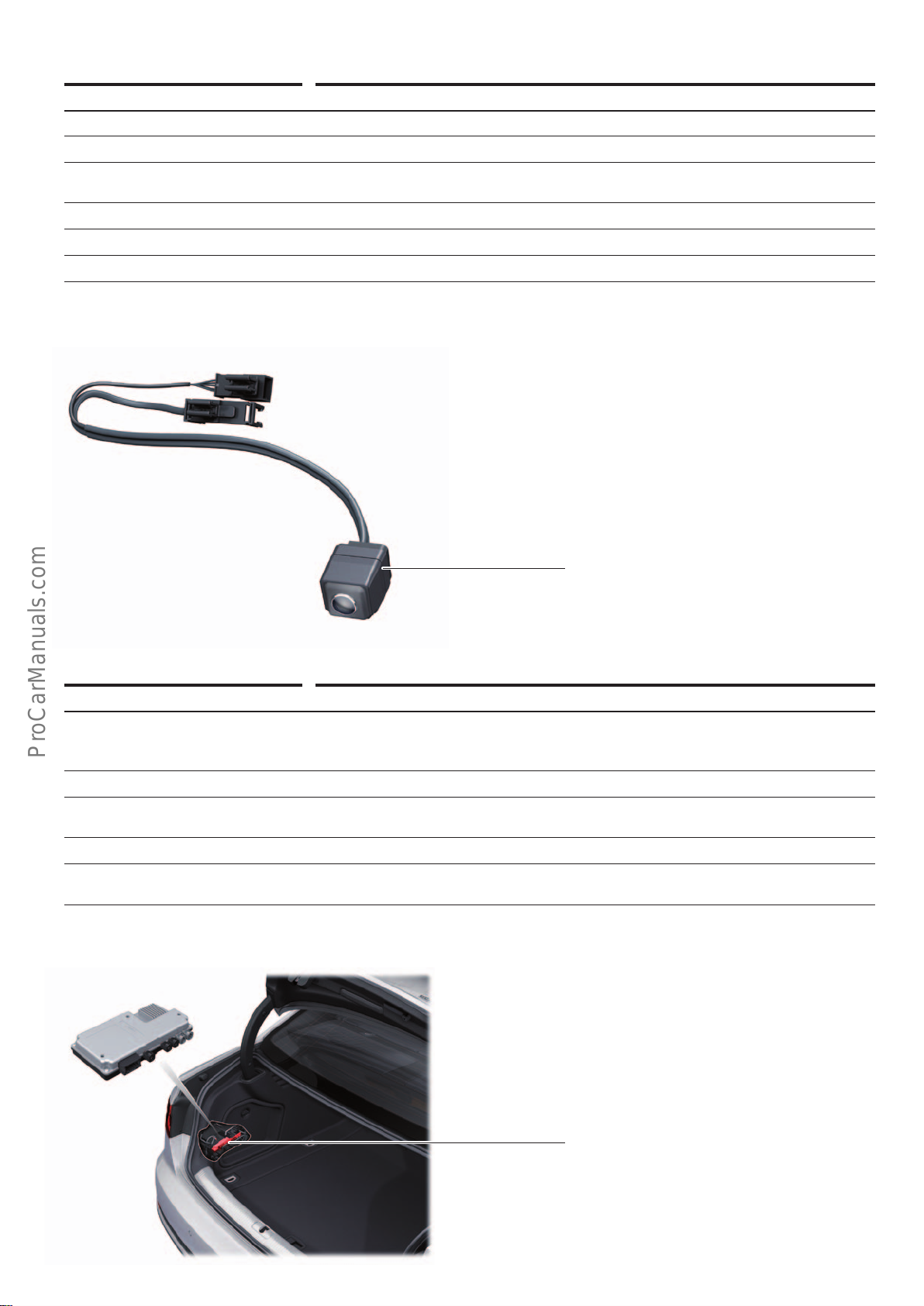
Designation Rear view camera system control unit J772
Equipment Optional equipment (PR no.: KA2)
Installation location In handle (soft touch) on rear hatch
Task Processing and transfer of images from the area behind the vehicle to the information elec-
tronics control unit 1 J794
Diagnostic address 6C
Data bus communication Extended CAN subscriber
Special feature Control unit, camera and wiring harness form a unit (as shown)
Rear-view camera system control unit
J772
(with built-in camera)
Surround cameras
Designation Surround camera control unit J928
Equipment Optional equipment, available in combination with:
Installation location In luggage compartment, L/H side, behind luggage compartment side trim
Task The control unit reads in the data from the 4 surround-view cameras and generates images
Diagnostic address 6C
Data bus communication • Extended CAN subscriber
• Parking aid plus (PR no.: 7X2)
• Park assist (PR no.: 7X5)
mapping the area around the vehicle.
• Image transfer to instrument cluster by LVDS
646_033
Surround camera control unit
J928
646_034
33
Page 34
Auxiliary heating
< Back
Forward >
Ξ Contents
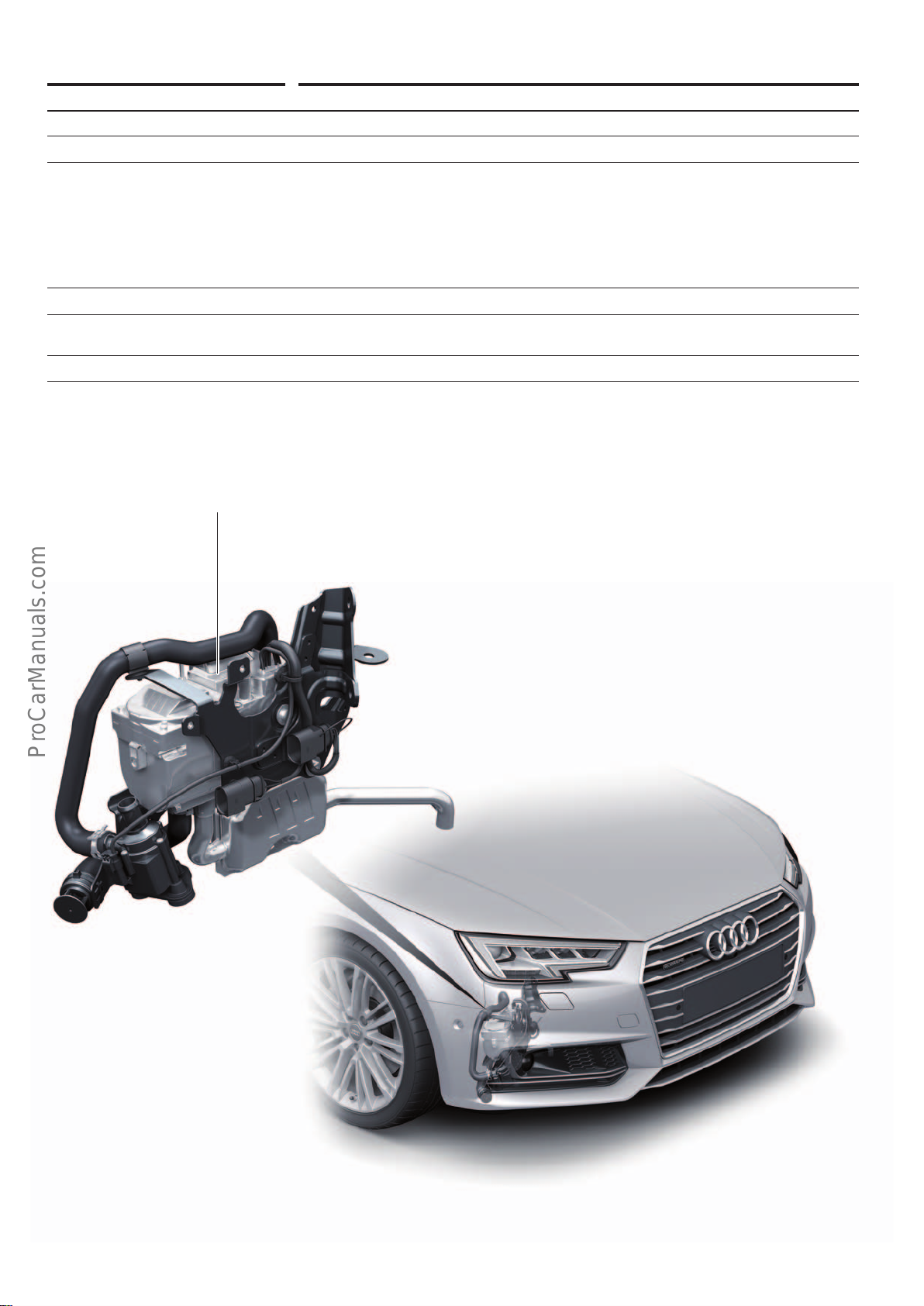
Designation Auxiliary heater control unit J364
Equipment Optional equipment (PR no.: 9M9)
Installation location In front wheel arch, R/H side, on side member
Tasks • Reading (senders/sensors/switches)
• Temperature sensor, flame monitor
• Switch-on signals of auxiliary heating radio receiver
• Activation (actuators/control elements)
• Fuel metering pump, combustion air blower
• Heater glow plug, heating element for fuel preheating
• Coolant circulation pump, heater coolant shut-o valve
Diagnostic address 18
Data bus communication • Extended CAN subscriber
• LIN master for auxiliary heating radio receiverR64
Special feature Control unit integrated in heater
Auxiliary heating control unit
J364
646_035
34
Page 35
Audi side assist
< Back
Forward >
Ξ Contents
Designation Audi side assist control unit J769 (master)
Audi lane assist control unit 2 J770 (slave)
Equipment Optional equipment (PR no.: 7Y1)
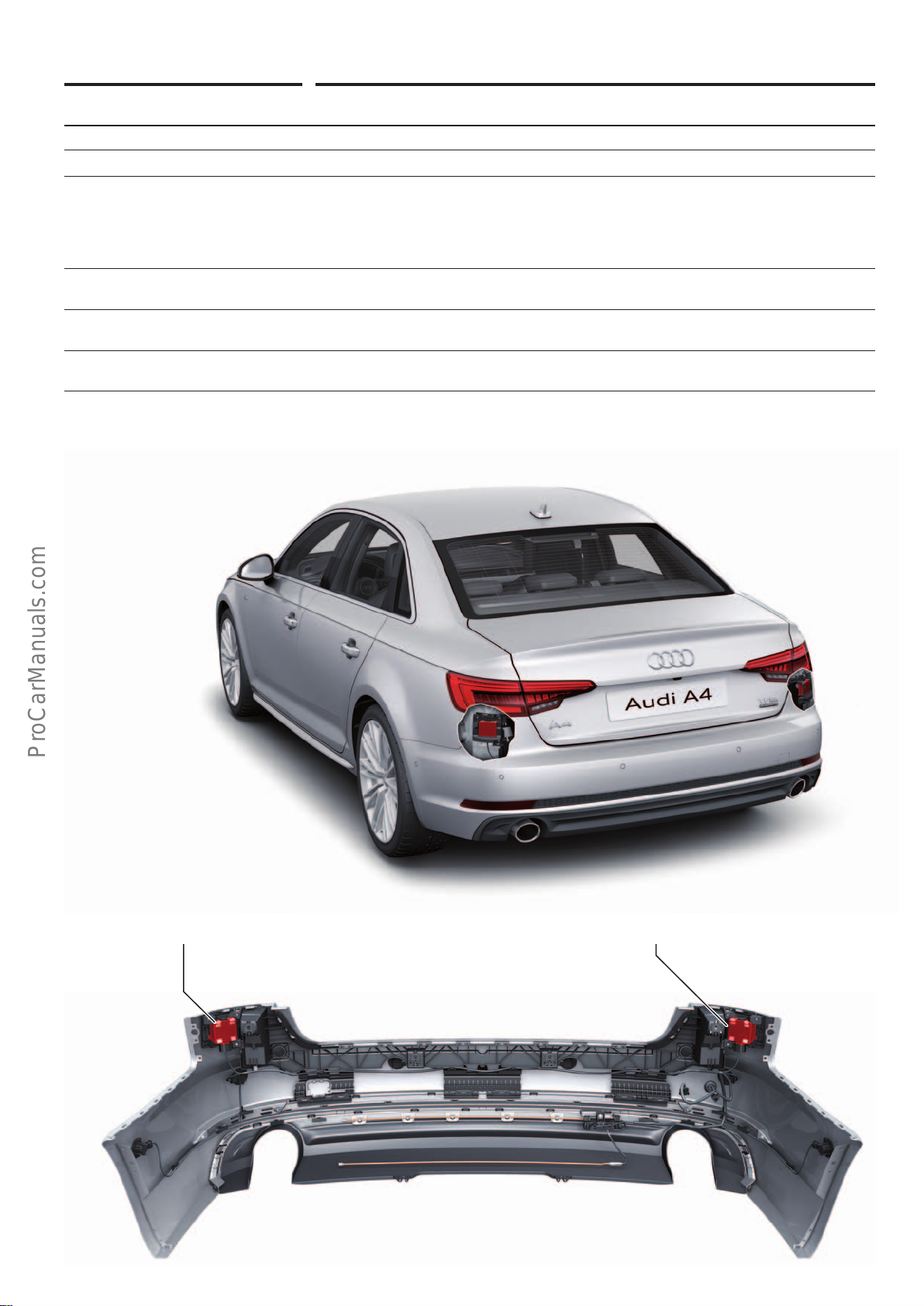
Installation location In rear bumper cover, left and right
Tasks Radar monitoring system for the detection of vehicles (cycles and automobiles) in the area to
the rear and side of the vehicle for
• Audi pre sense rear including Audi side assist
• Rear cross trac assist
• Exit warning
Diagnostic address • 3C–J769 (master)
• CF–J770 (slave)
Data bus communication • Extended CAN subscriber
• Both control units are also interconnected by a sub-bus system.
Special feature The control unit is integrated in the bumper cover. The system has to be calibrated after
removal and installation.
Audi side assist control unit
J769
Audi side assist control unit 2
J770
646_036
35
Page 36
Electronic Stability Control (ESC)
< Back
Forward >
Ξ Contents
Designation ABS control unit J104
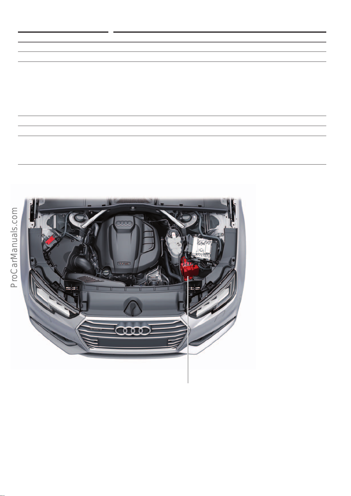
Equipment Always fitted
Installation location In engine bay, L/H side
Tasks Controlling:
• Anti lock braking system (ABS)
• Electronic Stability Control (ESC)
• Traction Control System (TCS)
• Electronic Dierential Lock (EDL)
• Torque vectoring
• Multicollision brake
• Electro-mechanical parking brake (EPB)
Diagnostic address 03
Data bus communication FlexRay subscriber
Special features • The control unit camn be replaced separately from the valve block. ESD protective mat
VAS6613 must be used.
• The electro-mechanical parking brake is integrated in the ABS control unit.
Address word53 is no longer used for electro-mechanical parking brake.
646_037
ABS control unit
J104
36
Page 37
Information electronics
< Back
Forward >
Ξ Contents
Designation Information electronics control unit 1 J794
Equipment Always fitted
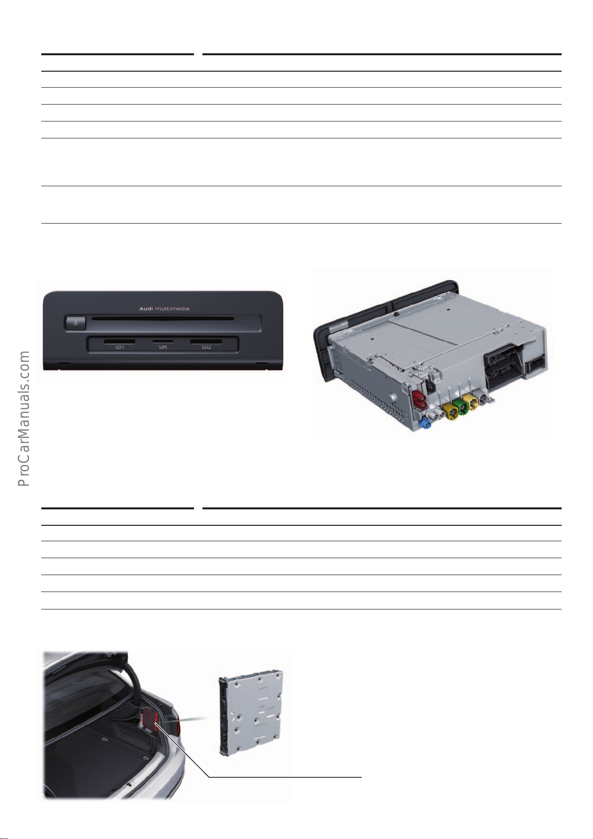
Installation location In glove compartment
Task Controlling the infotainment systems
Diagnostic address 5F
Data bus communication • Infotainment CAN bus user
• MOST subscriber
• J794 is connected to the MMI display J685 and the multimedia system operating unit E380
via the Modular Infotainment System (MIB) CAN.
Special features • J794 is the system manager and the ring break diagnostics master for the MOST bus.
• J794 is connected to the dash panel insert control unit J285 and the MMI display J685 via
LVDS bus (image transfer for navigation display in instrument cluster or MMI display).
Information electronics control unit 1
J794
Information electronics control unit 1
J794
(back)
TV tuner
Designation TV tuner R78
Equipment Optional equipment (PR no.: QV1)
Installation location In luggage compartment, R/H side, behind luggage compartment side trim
Task TV reception
Diagnostic address 57
Data bus communication MOST subscriber
646_038
TV tuner
R78
646_039
37
Page 38
Sound amplifier
< Back
Forward >
Ξ Contents
Designation Digital sound package control unit J525
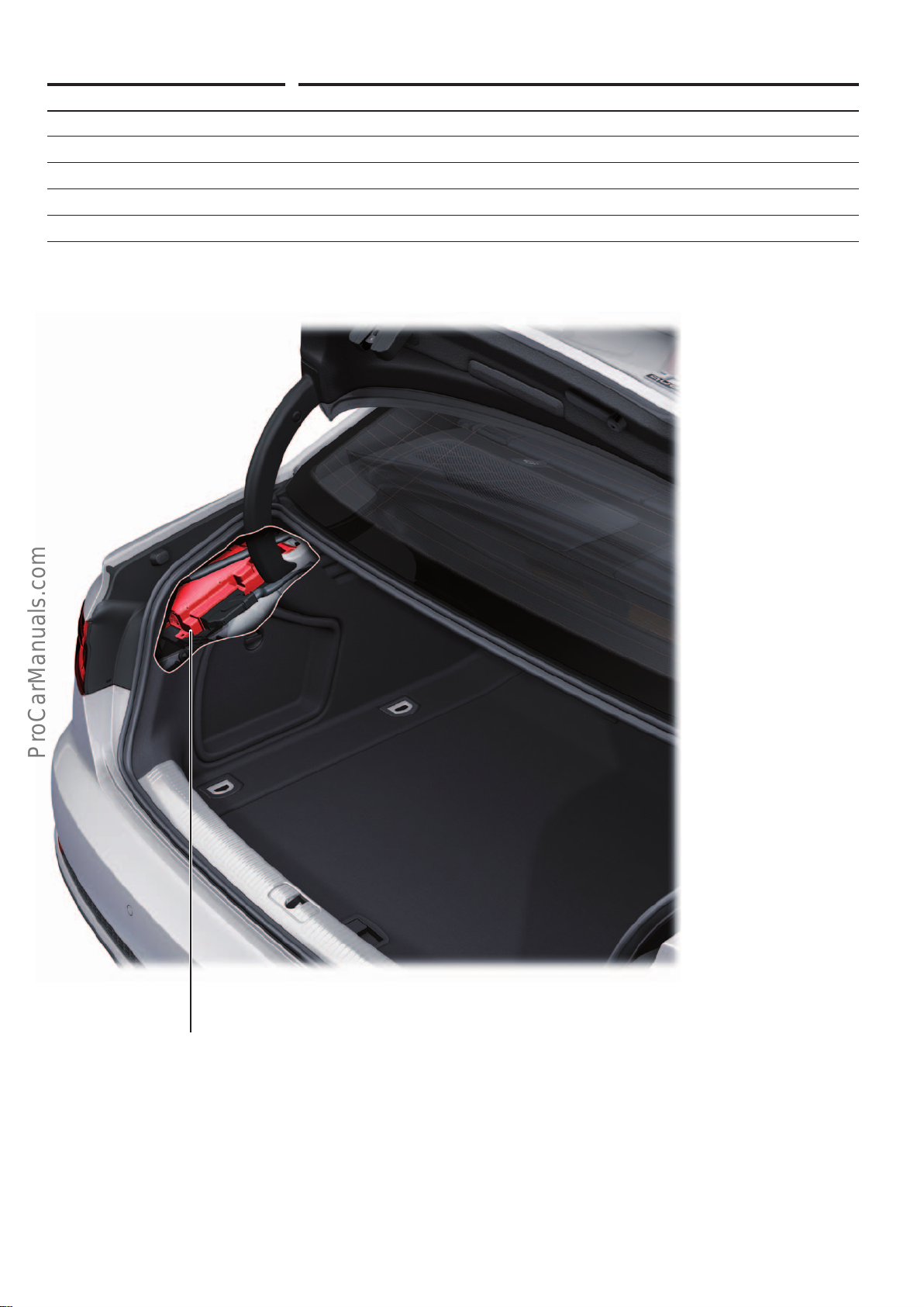
Equipment Optional equipment (PR no.: 9VS)
Installation location In luggage compartment, L/H side, behind luggage compartment side trim
Task Activation of up to 19 speakers
Diagnostic address 47
Data bus communication MOST subscriber
Digital sound package control unit
J525
646_040
38
Page 39
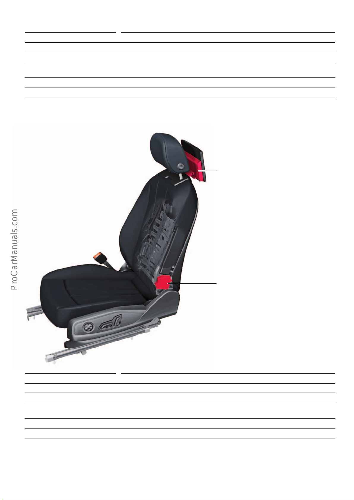
Rear Seat Entertainment (Auditablet)
< Back
Forward >
Ξ Contents
Designation Control unit for rear left information display and operating unit J648
Equipment Optional equipment (PR no.: 9WE or 9WF)
Installation location In the driver seat backrest
Task Interface between the Auditablet for Rear Seat Entertainment, rear left and the vehicle elec-
tronics
Diagnostic address 5E
Data bus communication Modular Infotainment System CAN subscriber
Bracket for multimedia system display unit 3
R315
Designation Control unit for rear right information display and operating unit J649
Equipment Optional equipment (PR no.: 9WE or 9WF)
Installation location In the front passenger seat backrest
Task Interface between the Auditablet for Rear Seat Entertainment, rear right and the vehicle elec-
tronics
Diagnostic address 4E
Data bus communication Modular Infotainment System CAN subscriber
Control unit for rear left information display
and operating unit
J648
646_041
39
Page 40
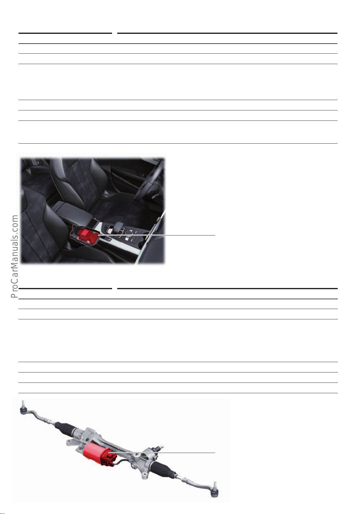
Suspension control unit
< Back
Forward >
Ξ Contents
Designation Suspension control unit J775
Equipment Optional equipment
Installation location Under centre console, front, on centre tunnel
Tasks Wheel damping control
• Reading (senders/sensors/switches)
• Level control system sensor (4pcs.)
• Activation (actuators/control elements)
• Damper adjustment valve (4 pce.)
Diagnostic address 74
Data bus communication FlexRay subscriber
Special feature The suspension control unit J775 is responsible for driving dynamics control. In models with a
sport dierential, J775 sends the commands to the all-wheel drive control unit J492, where
these commands are put into action.
Suspension control unit
J775
646_042
Power steering
Designation Power steering control unit J500
Equipment Always fitted
Installation location Connected to the steering gear.
Tasks Controlling:
• power steering
• Servotronic speed-responsive power steering
• Corrective steering inputs in conjunction with Audi active lane assist, park assist, evasion
assist and trailer assist
• Corrective steering inputs in conjunction with ESC
Diagnostic address 44
Data bus communication FlexRay subscriber
Special feature The control unit with power steering motor can only be replaced together with the steering gear.
Power steering control unit
J500
646_043
40
Page 41
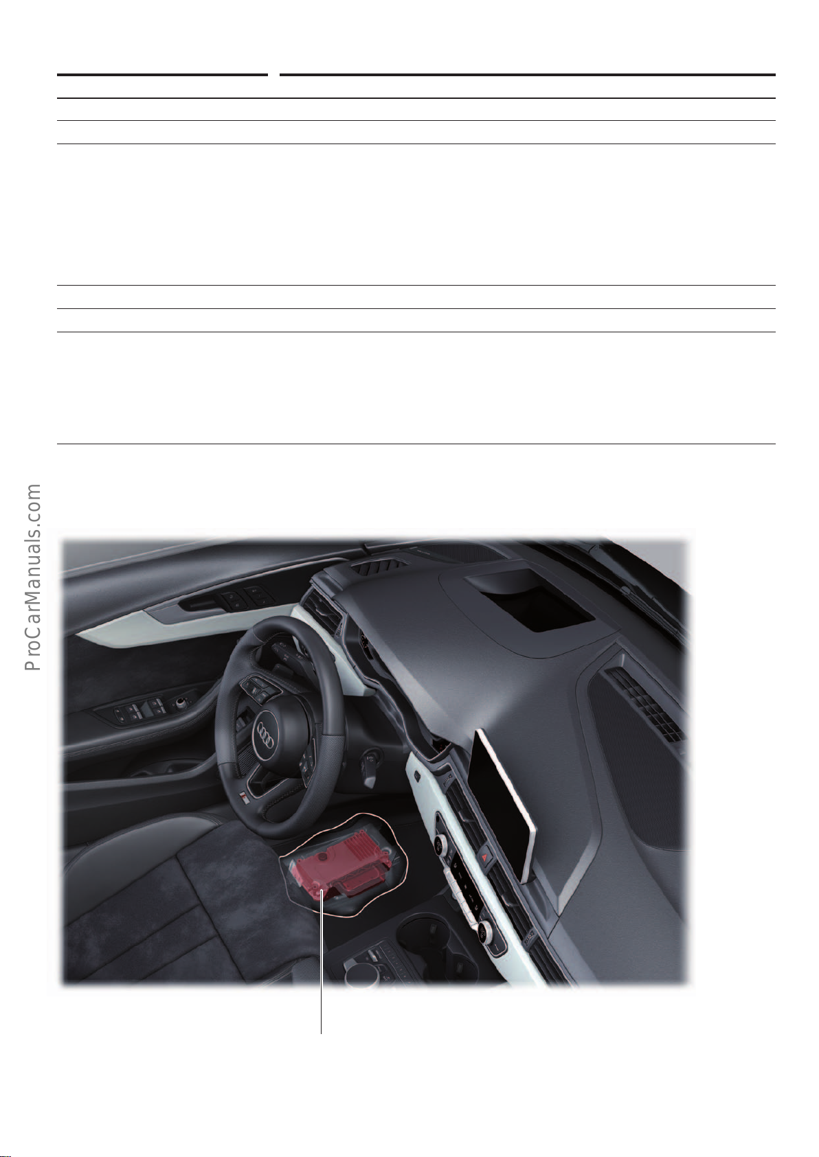
Dynamic steering
< Back
Forward >
Ξ Contents
Designation Active steering control unit J792
Equipment Optional equipment (PR no.: 1N8)
Installation location In driver's side footwell, under the floor covering
Tasks • Calculating the superimposition angle required to implement the variable steering ratio.
• Correcting the calculated superimposition angle of the stabilising function through ESC
intervention.
• Reading (senders/sensors/switches)
• Index sensor
• Motor position sensor
• Activation (actuators/control elements)
• Dynamic steering actuator
• Dynamic steering lock
Diagnostic address 1B
Data bus communication FlexRay subscriber
Special features Basic setting is necessary after:
• replacement by a new or dierent active steering control unit J792
• replacement by a new or dierent steering column
• replacement by a new or dierent steering angle sensor G85 or recalibration
• Changing the wheel alignment values
• Disconnecting the actuator from the steering column or the actuator from the steering
gear
646_044
Active steering control unit
J792
41
Page 42
Exterior lighting
< Back
Forward >
Ξ Contents
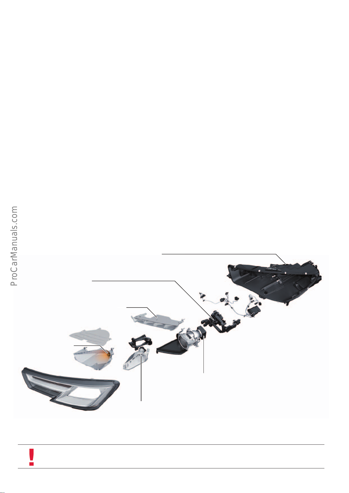
Headlight variants
In the case of the Audi A4, a distinction is made between the
following headlight versions:
• Xenon headlight (ECE1) and SAE2))
• LED headlight (ECE1) and SAE2))
• Audi Matrix LED headlight (ECE1))
To remove headlights, the bumper cover must be taken o beforehand. The headlights are connected to the vehicle body by means
of adjusting elements. Thus, it is possible to align the headlights
exactly with the other body parts. Before the headlight can be
removed from the vehicle, the headlight washer nozzle must be
unclipped from the headlight.
Xenon headlight
The figure shows the left headlight in the ECE1) version.
Sealing cover in headlight housing –access for changing bulb in foglight
"Service"
Headlight range control servomotor
V48
In the event of damage to the upper and inner headlight attachments, repair tabs can be attached to the headlight housing. The
parts marked "Service" in the exploded-view diagrams of the
headlights on the following pages can be replaced individually in
the event of damage.
For information as well as the corresponding spare part numbers,
please refer to the workshop manual or the electronic parts catalogue.
Reflectors for LED daytime running light and side light
Turn signal bulb, front left
M5
"Service"
1)
ECE = for European market
2)
SAE = for North American Region
Note
"Fog light bulb L22" (for the all-weather light function) can be accessed via a cover on the back of the headlight housing and
can be replaced after the headlight has been installed.
Fog light bulb, left
L22
"Service"
Left gas discharge lamp
L13
"Service"
646_054
42
Page 43
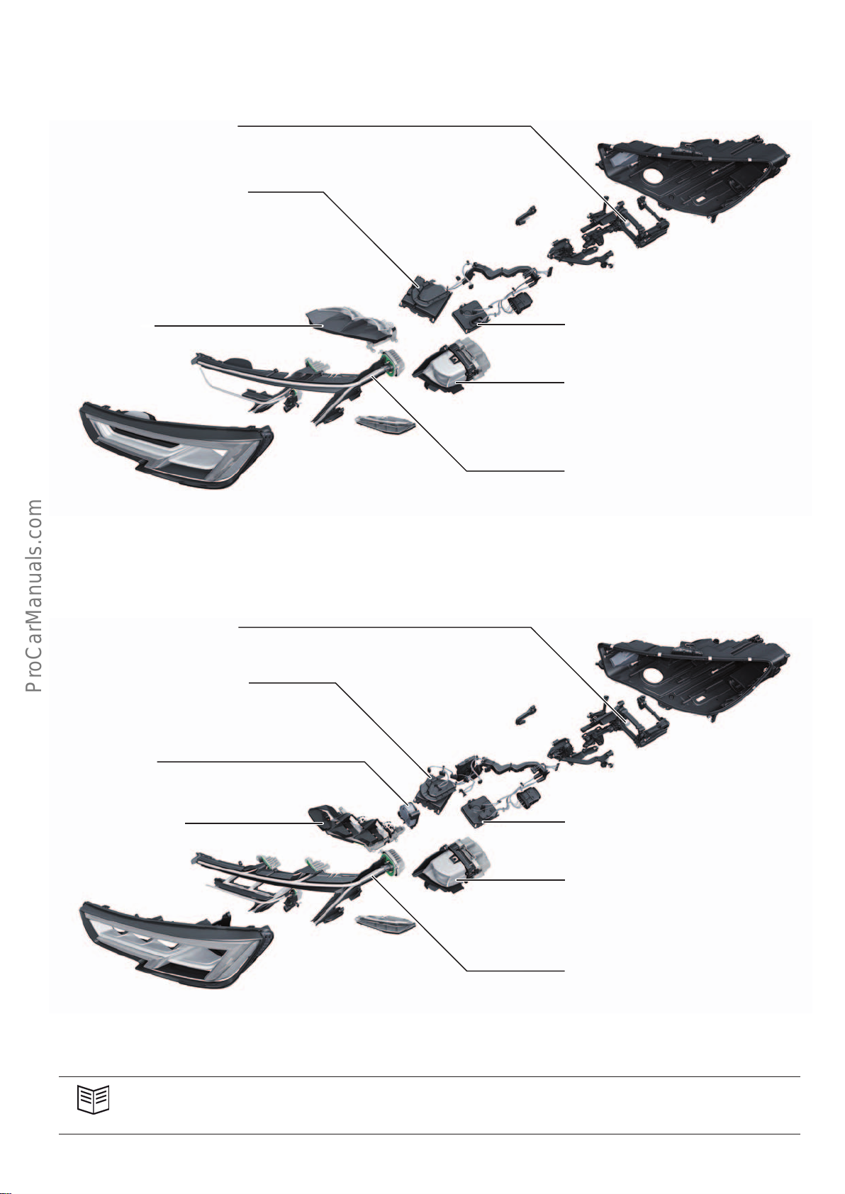
LED headlights
< Back
Forward >
Ξ Contents
The figure shows the left headlight in the ECE1) version.
Headlight range control servomotor
V48
Power module 1 for left LED headlight
A31
"Service"
Headlight module
Audi Matrix LED headlight
The figure shows the left headlight.
Headlight range control servomotor
V48
Power module 1 for left LED headlight
A31
"Service"
Control unit for light control, left
J1018
"Service"
Dipped beam module
Fibre optic cable for daytime running light /
side light, turn signal
646_055
Left headlight fan
V407
Matrix headlight module
1)
ECE = for European market
2)
SAE = for North American Region
Reference
For information on parts replaceable by service centres and the corresponding spare part numbers, please refer to the
workshop manual or the electronic parts catalogue.
Control unit for light control, left
J1018
"Service"
Dipped beam module
Fibre optic cable for daytime running light /
side light, turn signal
646_056
43
Page 44
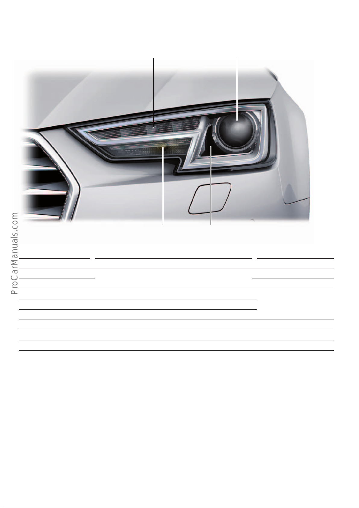
Xenon headlight
< Back
Forward >
Ξ Contents
The figure shows the L/H headlight in the ECE1) version.
Daytime running light/
parking light
Dipped beam/
main beam
646_057
Turn signal All weather light
Light functions Type of bulb used Power
Daytime running light 4 LEDs 5watts
Side light Parking light is dimmed if light function is active
Dipped beam Gas discharge lamp D5S 25watts
Motorway light (only ECE
1)
) Raises dipped beam by means of headlight range adjustment
Main beam Changes over dipped beam using shutter
All weather light Bulb H8 35watts
Turn signal Bulb PSY24W 24watts
2)
Sidemarker (SAE only
) 1 LED 0.5watts
Special features of the light functions
The daytime running lights in the ECE1) version are dimmed for the
duration of the turn signaling cycle (in the SAE2) version they are
switched o). The all-weather light in both versions is deactivated
during the turn signalling cycle as soon as the vehicle exceeds a
speed of 40 kph.
The left and right dipped beam shutter motors V294 and V295 are
used for switching between dipped beam and main beam. The
LEDs for the side light function and the dipped beam function of
the gas discharge lamp are used for the Coming Home / Leaving
Home function.
1)
ECE = for European market
2)
SAE = for North American Region
44
Page 45
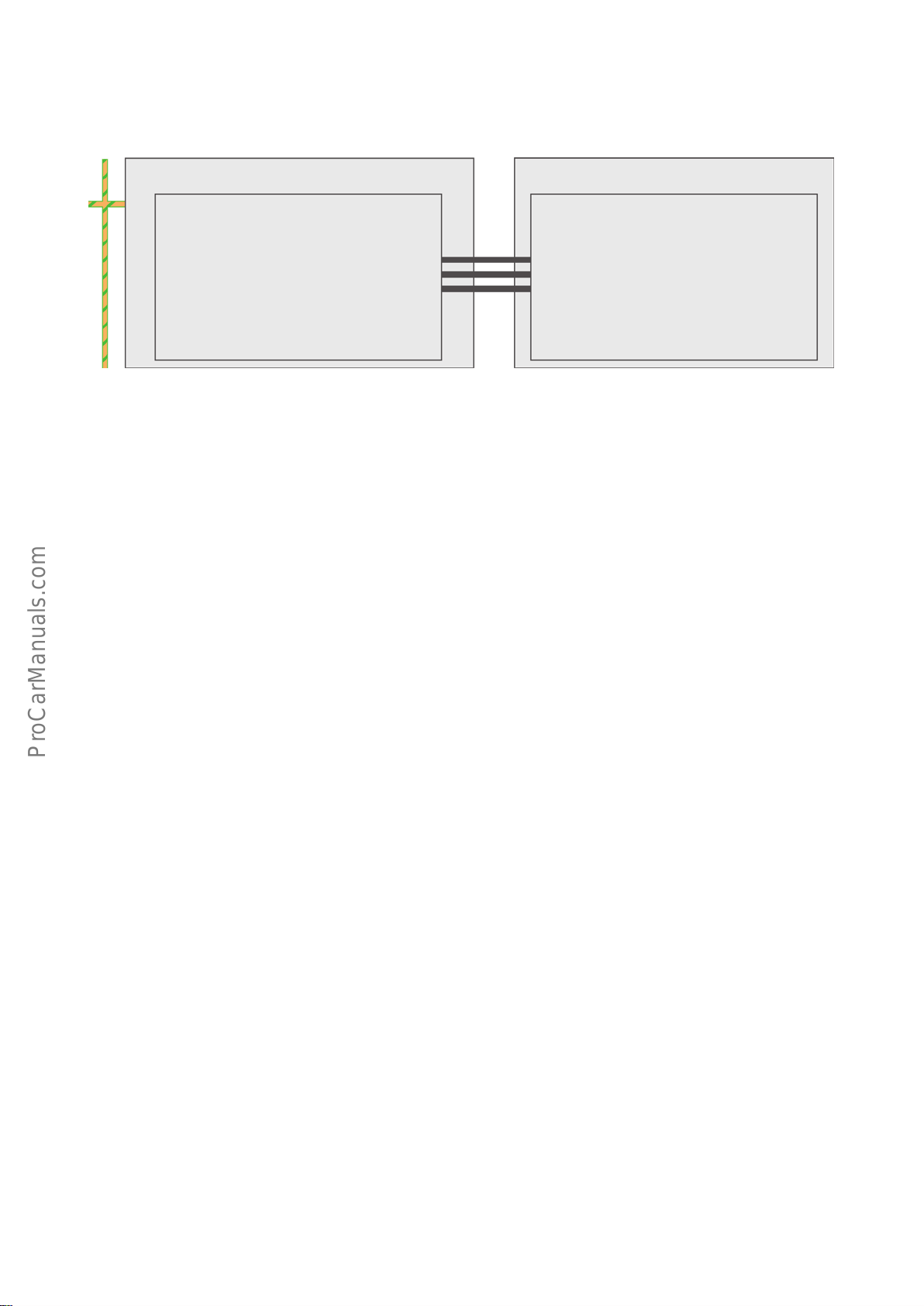
Schematic diagram of the activation mechanism
< Back
Forward >
Ξ Contents
Electrical system control unit
J519
• Voltage supply
• Activation of light functions
• Calculation/activation of headlight range adjust-
ment
Convenience CAN
Gas discharge headlight
(L/H side of vehicle)
• Control unit
• Dipped beam shutter
• Fog light bulb, left
• Turn signal bulb, front left
Discrete lines
• LEDs for parking lights and daytime running lights
• LEDs for front left side marker light (SAE
• Beam-height adjustment servo motor
2)
)
646_058
Activation
If the vehicle is equipped with xenon headlights, the electrical
system control unit J519 is responsible for power supply as well as
for activating all bulbs in the headlight. J519 also activates the
dipped beam shutter and the headlight range adjustment control
motor.
Headlight range adjustment
The gas discharge headlight has automatic static headlight range
adjustment. This means that changes in headlight range are
compensated by loading of the vehicle. However, changes caused
by rolling movements of the vehicle under acceleration and braking
are not compensated.
The electrical system control unit receives information on ride
height from either the central control unit for comfort/convenience system J393 or, if installed, the suspension control unit J775.
Service
The basic setting of the headlight range adjustment function is
configured in the electrical system control unit J519. The foglamp
bulb can be replaced with the headlights fitted. This bulb can be
accessed via a cover on the back of the headlight housing. The
headlight must be removed in order to replace the gas discharge
lamp or the turn signal lamp.
Adaptation for driving on the opposite side of the road
It is not necessary to adapt the headlights. No further action is
needed in order to meet the statutory requirements.
Optional equipment
The xenon headlight can be combined with main beam assist
(PRno.: 8G1) as well as a headlight washer system (PR no.: 8X1).
1)
ECE = for European market
2)
SAE = for North American Region
45
Page 46
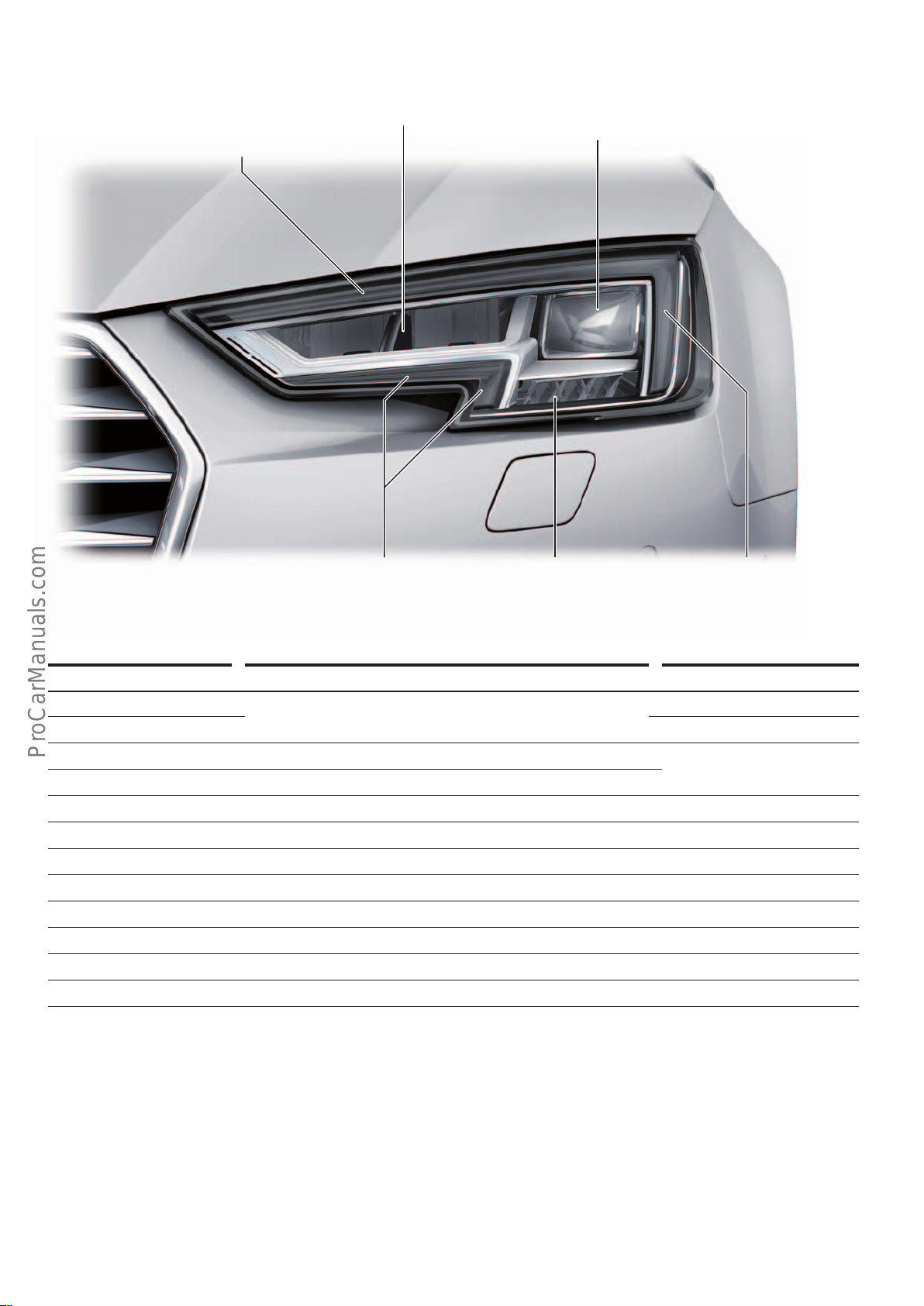
LED headlight
< Back
Forward >
Ξ Contents
The figure shows the L/H headlight in the ECE1) version.
Daytime light/
side light/
turn signal
Main beam Dipped beam/
motorway light
646_059
Daytime running light/
parking light
Turning light/
all-weather light/
static cornering light/
intersection light/
town light
Light functions Type of bulb used Power
Daytime running light 7LEDs with plastic optical fibres 18watts
Side light Parking light is dimmed if light function is active
Dipped beam 11 LEDs 20watts
Motorway light Raises dipped beam by means of headlight range adjustment
Main beam 6 LEDs 20watts
All weather light 3 LEDs 10watts
Turning light 0–40kph, turn signal responsive
Static cornering light 0–70kph, steering angle responsive
Intersection light (only ECE
Town light (only ECE
1)
) Turning light on both sides and dipped beam
1)
) Dimmed turning light on both sides and dimmed dipped beam
Turn signal 8 LEDs 18watts
2)
Sidemarker (SAE only
) 1 LED 0.5watts
Daytime running light/
parking light
Special features of the light functions
The "upper" daytime running light is dimmed for the duration of
the turn signalling cycle. The "lower" daytime running light is
dimmed to side light level. This applies to both the ECE1) version
and the SAE2) version. The all-weather light, the intersection light
and the town light are not aected by turn signal operation.
1)
ECE = for European market
2)
SAE = for North American Region
46
The LEDs for the side light function and the dipped beam function
are used for the Coming Home / Leaving Home function.
Page 47
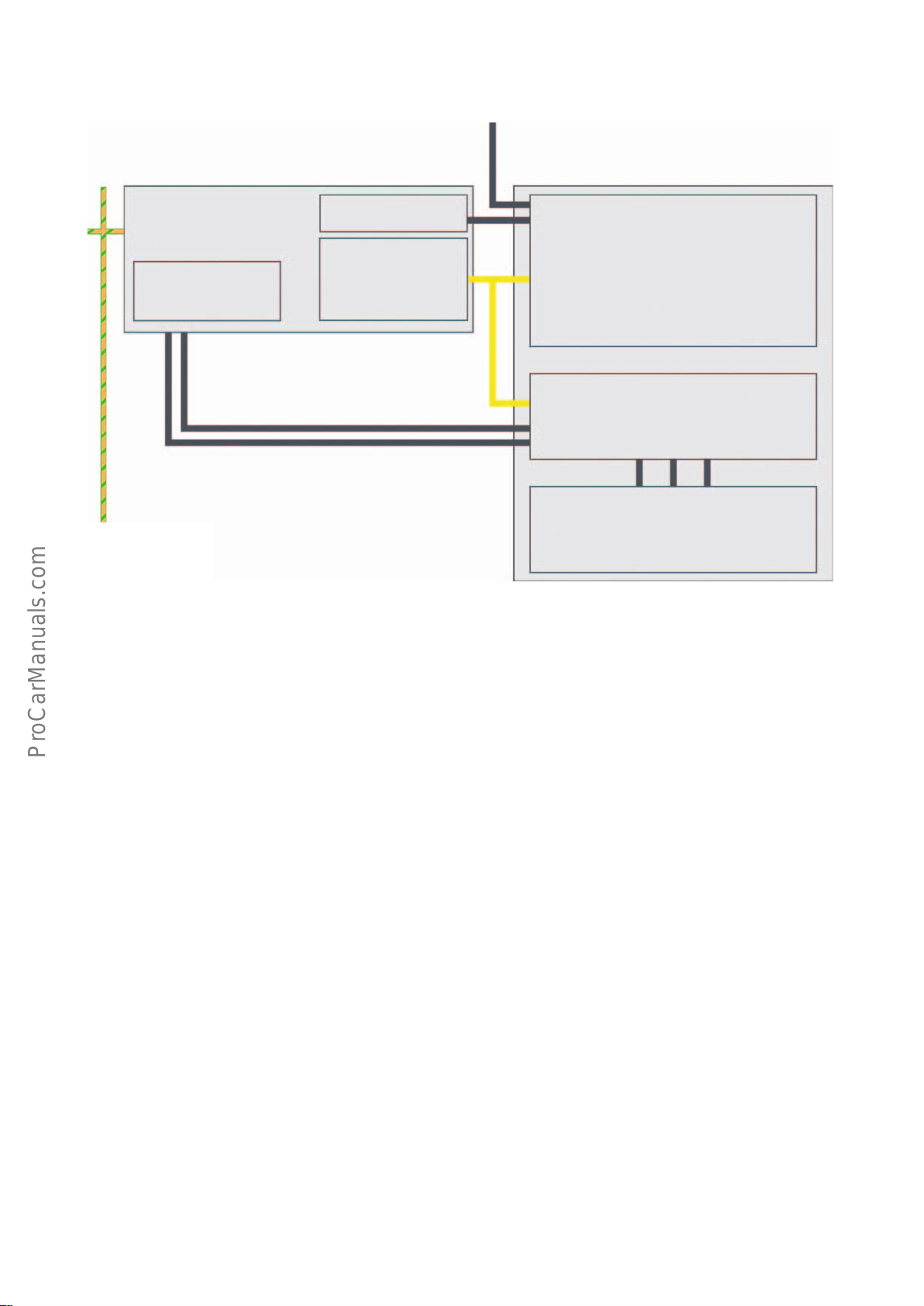
Schematic diagram of the activation mechanism
< Back
Forward >
Ξ Contents
External terminal 15 supply
LED headlights
(L/H side of vehicle)
Electrical system control unit
J519
Voltage supply
Convenience CAN
Discrete lines
Voltage supply
• Activation of light functions
• Calculation/activation of
headlight range adjustment
Discrete line
Sub-bus system
Power module 1 for left LED headlight A31
• LEDs for left dipped beam headlight
• LEDs for left dipped beam headlight
• LEDs for left static cornering light
Control unit for light control, left J1018
• LED for left side marker light (SAE
• Left headlight range control motor
Left LED module for daytime running lights and parking
lights L176
• LEDs for parking lights and daytime running lights
• LEDs for left turn signal
2)
)
Discrete lines
646_060
Activation
If the car has LED headlights, the electrical system control unit
J519 supplies voltage to power modules 1 for left/right LED
headlight A31/A27 and the left/right control units for light control
J1018/J1023. J519 also communicates with these control units via
a sub-bus system.
Power modules 1 for left/right LED headlight A31/A27 are responsible for activating the LEDs for dipped beam, main beam and
static cornering light (turning light). The control units have self
diagnostic capability and can be accessed using address
codesD6/D7.
The left/right control units for light control J1018/J1023 are
responsible for the parking light/daytime running light, turn
signals, side marker light (SAE2)) and the headlight range adjustment servomotor. The control units have self diagnostic capability
and can be accessed using address codes 29/39.
Headlight range adjustment
The LED headlight has automatic dynamic headlight range adjustment. Changes in the range of the headlight beam due to loading
of the vehicle as well as braking and accelerating are compensated.
The electrical system control unit receives information on ride
height from either the central control unit for comfort/convenience system J393 or, if installed, the suspension control unit J775.
Service
The basic setting of the headlight range adjustment function is
configured in the electrical system control unit J519. LED headlight bulbs cannot be replaced. Only the outer control units can be
replaced individually after removing the headlights.
Adaptation for driving on the opposite side of the road
It is not necessary to adapt the headlights. No further action is
needed in order to meet the statutory requirements.
Optional equipment
The LED headlight can be combined with main beam assist
(PRno.:8G1) as well as a headlight washer system (PR no.: 8X1).
1)
ECE = for European market
2)
SAE = for North American Region
47
Page 48
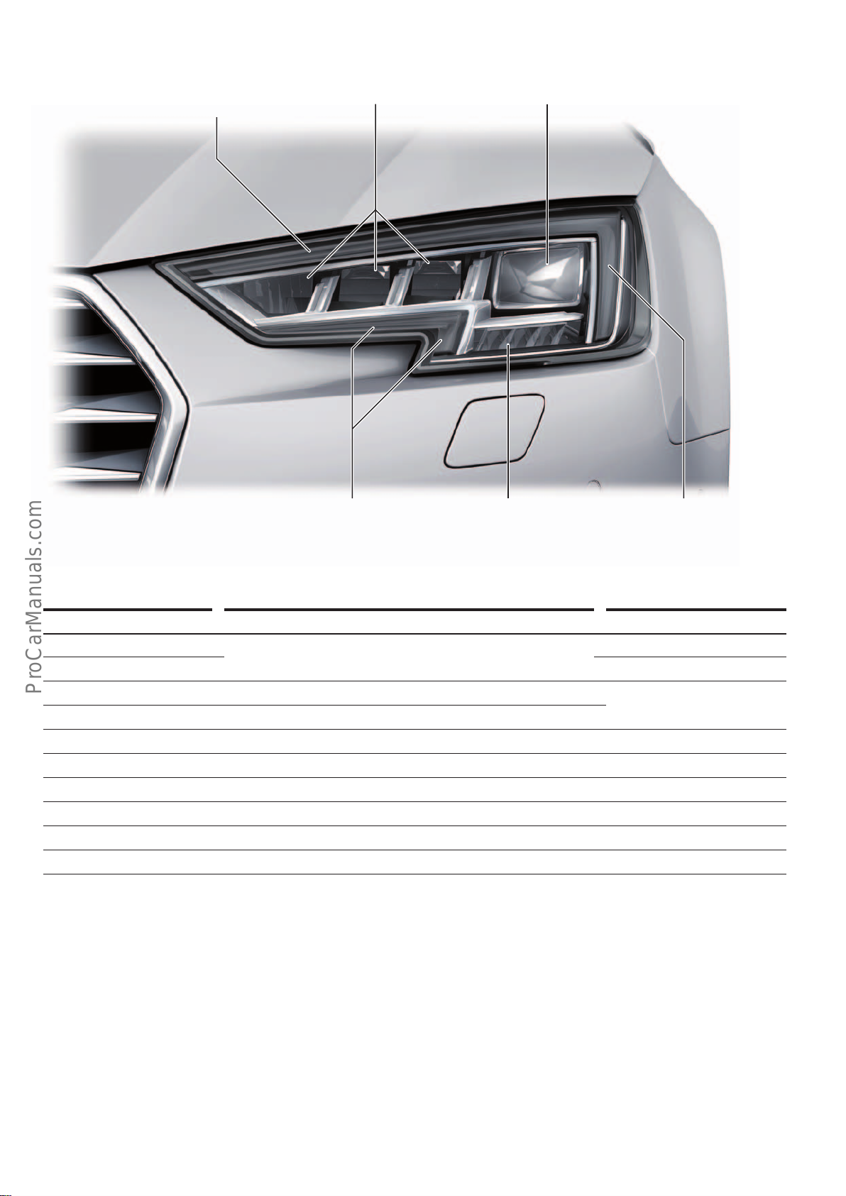
Audi Matrix LED headlight
< Back
Forward >
Ξ Contents
Daytime light/
side light/
turn signal
Main beam/
Matrix Beam headlight
Dipped beam/
motorway light
646_061
Daytime running light/
parking light
Turning light/
all weather light/
intersection light/
town light
Light functions Type of bulb used Power
Daytime running light 7LEDs with plastic optical fibres 18watts
Side light Parking light is dimmed if light function is active
Dipped beam 11 LEDs 20watts
Motorway light Raises dipped beam by means of headlight range adjustment
Matrix Beam headlight 12 LEDs 29watts
Turning light 3 LEDs 10watts
All weather light Dimmed turning light on both sides and dimmed dipped beam
Intersection lights Turning light on both sides and dipped beam
Town light Dimmed turning light on both sides and dimmed dipped beam
Turn signal (dynamic) 9 LEDs 18watts
Daytime running light/
parking light
Special features of the light functions
The "upper" daytime running light is dimmed for the duration of
the turn signalling cycle. The "lower" daytime running light is
dimmed to side light level. The Audi MatrixLED headlight supports
the dynamic turn signal function. The all-weather light, the intersection light and the town light are not aected by turn signal
operation.
48
The LEDs for the side light function and the dipped beam function
are used for the Coming Home / Leaving Home function.
The Audi MatrixLED headlight is not available in the North American Region.
Page 49
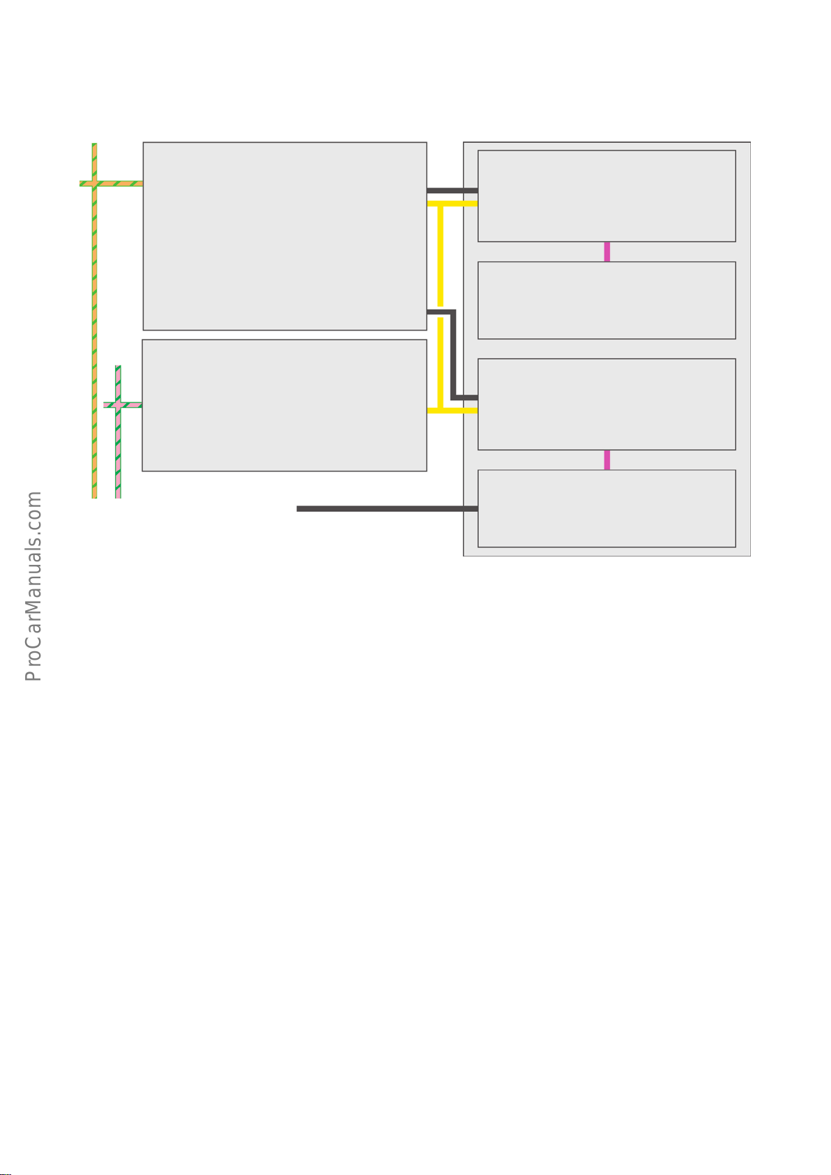
Schematic diagram of the activation mechanism
< Back
Forward >
Ξ Contents
Audi Matrix LED headlights
(L/H side of vehicle)
Convenience CAN
FlexRay
Electrical system control unit
J519
• Voltage supply
• Activation of light functions
• Calculation/activation of headlight range adjustment
Front camera for driver assistance systems
R242
• Monitoring trac
• Oncoming trac and vehicles ahead
• Calculation/activation of the Matrix Beam headlight
External terminal 15 supply
Control unit for light control, left J1018
Discrete line
• Left headlight range control motor
Left power module for headlight auxiliary functions
A47
Discrete line
• Dynamic turn signal function
• Daytime running light / parking light
Power module 1 for left LED headlight A31
• LEDs for left dipped beam headlight
Sub-bus system
• LEDs for left dipped beam headlight
• LEDs for left cornering light
• Left headlight fan
Left power module for Matrix headlight A44
LIN
LIN
Activation
If the car has Audi Matrix headlights, the electrical system control
unit J519 supplies voltage to power modules 1 for left/right LED
headlight A31/A27 and the left/right control units for light control
J1018/J1023. J519 also communicates with these control units via
a sub-bus system.
Power modules 1 for left/right LED headlight A31/A27 are responsible for activating the LEDs for dipped beam, main beam and
static cornering light (turning light) and the headlight fan. In
addition, they are connected to the LED modules for the Matrix
Beam headlight via a LIN line. The control units have self diagnostic capability and can be accessed using address codes D6/D7.
The left/right control units for light control J1018/J1023 are
responsible for the parking light/daytime running light and the
headlight range adjustment servomotor. The control units have
self diagnostic capability and can be accessed using address
codes29/39. The LED module for the dynamic turn signal function
is activated via a LIN line.
The decision whether dynamic or conventional flashing is required
is sent from the electrical system control unit J519 to the left/right
control units for light control J1018/J1023 via the sub-bus line.
646_062
Headlight range adjustment
The Audi Matrix LED headlight supports automatic dynamic headlight range adjustment. Changes in the range of the headlight
beam due to loading of the vehicle as well as braking and accelerating are compensated.
The electrical system control unit receives information on ride
height from either the central control unit for comfort/convenience system J393 or, if installed, the suspension control unit J775.
Service
The basic setting of the headlight range adjustment function is
configured in the electrical system control unit J519. Matrix LED
headlight bulbs cannot be replaced. Only the outer control units
can be replaced individually.
Adaptation for driving on the opposite side of the road
It is not necessary to adapt the headlights. No further action is
needed in order to meet the statutory requirements.
1)
ECE = for European market
2)
SAE = for North American Region
49
Page 50
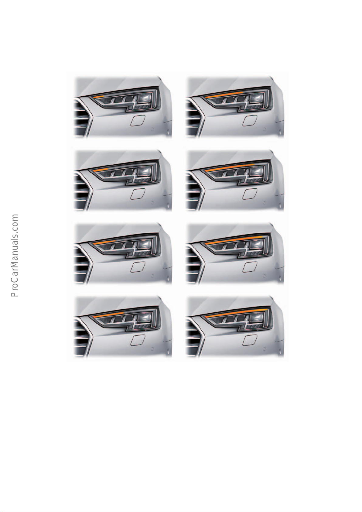
Dynamic turn signal function
< Back
Forward >
Ξ Contents
The dynamic turn signal function is implemented in the
AudiA4(type8W) both for the lighting of the ECE1) version and
the SAE2) version.
The LEDs illuminate in a sweeping motion from the inside outwards. The flashing LEDs all switch o simultaneously.
Activation
The electrical system control unit J519 instructs the headlights
and the central control unit for comfort/convenience system J393
to activate the turn signal function. J393 thereupon activates the
LEDs for the turn signal function in the tail lights. An electronic
module in the headlights or in the tail lights is responsible for
sequential activation of the LEDs.
Since sequential flashing is not desirable with all turn signal
functions, the electrical system control unit J519 informs the
headlights via a sub-bus system whether conventional or sequential flashing is required. The tail lights are supplied with the information from the central control unit for comfort/convenience
system J393 via a discrete line.
646_074
Conventional flashing is used, for example, to indicate a crash/
collision or an emergency or as a hazard warning after heavy
braking.
The dynamic turn signal function, on the other hand, is used when
indicating direction and when the hazard warning lights are manually activated, as well as for central locking acknowledgement and
after confirmation of successful programming.
Equipment
The dynamic turn signal function is implemented in the front end
of an AudiA4 with AudiMatrixLED headlights as well as in conjunction with all LED tail light versions.
1)
ECE = for European market
2)
SAE = for North American Region
50
Page 51
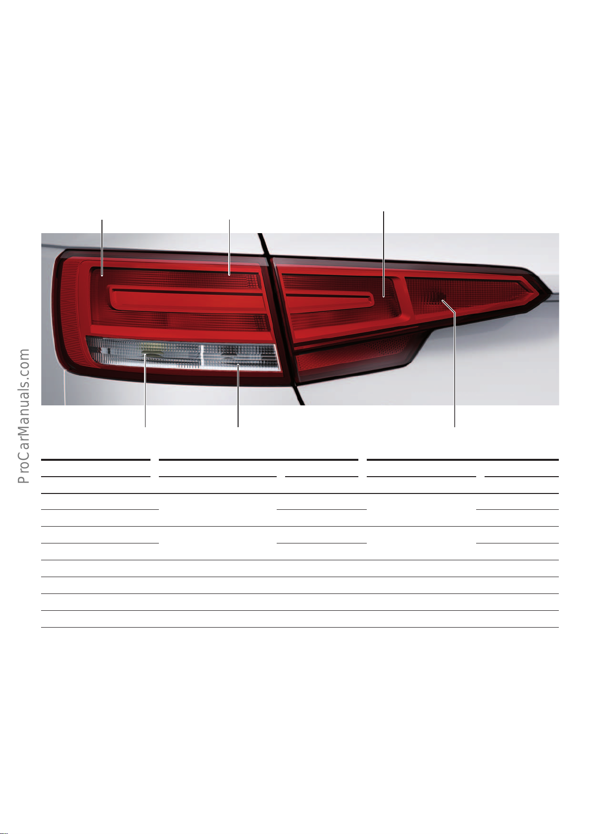
Tail lights
< Back
Forward >
Ξ Contents
In the AudiA4(type 8W) the rear light functions are distributed to
the tail lights in the body side panels and the tail lights in the rear
hatch. This statement applies equally to the AudiA4 saloon and
the AudiA4Avant. However, the various light functions are distributed dierently in the saloon and in the Avant (refer to tables).
Basic tail light (PR no.: 8SA)
The figure shows the L/H basic tail light of the Audi A4 saloon.
Brake light 1/
Tail light 1
Brake light 2/
Tail light 2
A distinction is made between the following versions of the tail
lights:
• ECE basic tail light
1)
• LED tail lights (ECE1) and SAE2))
The tail lights are activated irrespective of variant by the central
control unit for comfort/convenience system J393.
Tail light 3
Reversing light Rear fog lightTurn signal
Light functions Saloon Avant
Brake light 1 P21W
Tail light 1 25 % activation
Brake light 2 P21W
Tail light 2 32 % activation
Turn signal PY21W
Reversing light W16W
Tail light 3 W16W
Rear fog light
Special features of the light functions
The tail lights are also activated if the vehicle is equipped with a
Coming Home / Leaving Home function. The basic tail light does
not support the dynamic turn signal function. In the case of the
tail lights on the saloon model, the rear fog light is deactivated
5)
Bulb/lamp Power Bulb/lamp Power
H21W
3)
3)
3)
3)
3)
3)
4)
– 28% activation approx. 4.5watts W16W4) – 42 % activation approx. 7watts
4)
21watts W16W
approx. 5watts 28 % activation
21watts W16W
approx. 7watts 28 % activation
21watts PY21W
16watts W16W
21watts H21W
Service
To replace the bulbs/lamps in the tail lights, the light in question
must be removed. This applies to both the tail lights in the body
side panels and the tail lights in the rear hatch. All bulbs can be
replaced.
when the rear hatch is open. In the case of the tail lights on the
Avant model, the reversing light is also deactivated.
646_071
3)
3)
3)
3)
3)
4)
4)
16watts
approx. 4.5watts
16watts
approx. 4.5watts
21watts
16watts
21watts
1)
ECE = for European market
2)
SAE = for North American Region
3)
Tail lights in the body side panels
4)
Tail lights in the rear hatch
5)
One side only (L/H side only in RHD models, R/H side only in LHD models)
51
Page 52
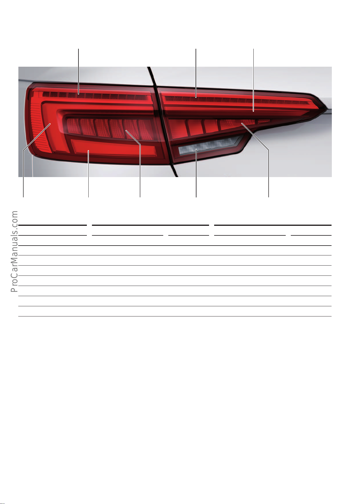
LED tail light (PR no.: 8SP)
< Back
Forward >
Ξ Contents
The figure shows the L/H LED tail light of the saloon model in the ECE1) version.
Turn signal Turn signal Tail light
646_072
Brake light Reversing light Rear fog lightTail light Tail light
Light functions Saloon
1)
Bulb/lamp Power Bulb/lamp Power
Turn signal (dynamic)
Tail light
Brake light
3)
3)
Turn signal (dynamic)
Reversing light
Tail light
4)
Rear fog light
3)
4)
4)
4), 5)
12 LEDs 10watts 12 LEDs 11watts
33 LEDs 10watts 30 LEDs 8watts
6 LEDs 6watts 9 LEDs 8watts
18 LEDs 20watts 15 LEDs 14watts
4 LEDs 6watts 2 LEDs 7watts
15 LEDs 4watts 18 LEDs 4watts
2 LEDs 4watts 2 LEDs 4watts
Special features of the light functions
The tail lights are also activated if the vehicle is equipped with a
Coming Home / Leaving Home function. Light functions are not
deactivated when the rear hatch is open.
The LED tail light supports the dynamic turn signal function.
1)
Avant
Service
No bulbs/lamps can be replaced in the LED tail light. In the event
of a fault, the complete lamp must be replaced.
1)
ECE = for European market
2)
SAE = for North American Region
3)
Tail lights in the body side panels
52
4)
Tail lights in the rear hatch
5)
One side only (L/H side only in LHD models, R/H side only in RHD models)
Page 53
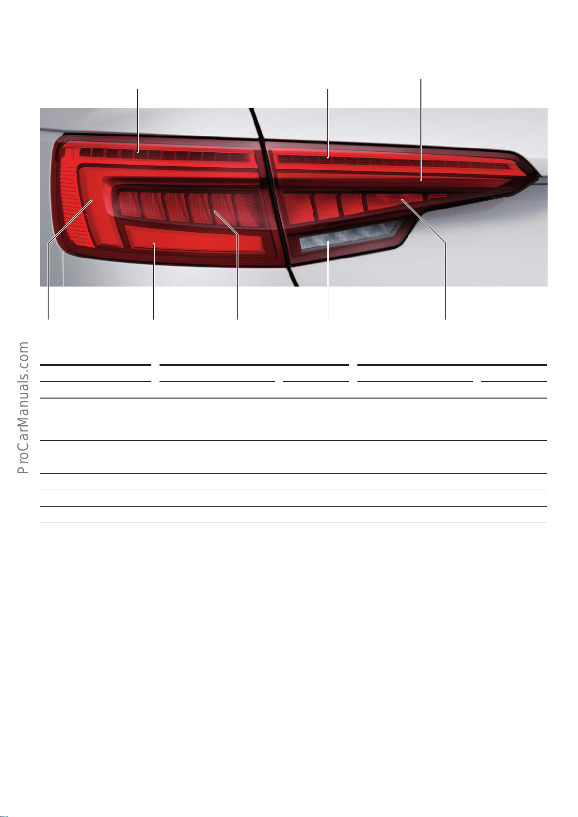
LED tail light (PR no.: 8SK)
< Back
Forward >
Ξ Contents
The figure shows the L/H LED tail light of the saloon model in the SAE2) version.
sidemarker
Brake light/
turn signal
Tail light Brake light
Brake light/
turn signal
Reversing light Rear fog lightTail light/
Tail light
646_073
Light functions Saloon
2)
Bulb/lamp Power Bulb/lamp Power
Brake light/turn signal
(dynamic)
Tail light
Brake light
Turn signal (dynamic)
Reversing light
Tail light
Rear fog light
3)
3)
3)
4)
4)
4)
4), 5)
12 LEDs 10watts 12 LEDs 14watts
33 LEDs 10watts 30 LEDs 8watts
6 LEDs 6watts 9 LEDs 14watts
18 LEDs 8watts 15 LEDs 9watts
4 LEDs 6watts 2 LEDs 7watts
15 LEDs 4watts 18 LEDs 5watts
2 LEDs 4watts 2 LEDs 4watts
Special features of the light functions
The tail lights are also activated if the vehicle is equipped with a
Coming Home / Leaving Home function. Light functions are not
deactivated when the rear hatch is open. If the tail light is activated and the brake light is simultaneously active, the LEDs for the
brake light/turn signal in the rear hatch lamp are deactivated. If
the tail light is activated and the turn signal is simultaneously
active, the LEDs for the brake light/turn signal in the rear hatch
lamp are also active. Amber-coloured LEDs are used for the turn
signal in the SAE
2)
version, while yellow LEDs are used in the ECE1)
version.
2)
Avant
In the case of the AudiA4, the dynamic turn signal function is also
supported in the SAE2) version. In this version, the LEDs for the
turn signal/brake light are briefly activated in a dimmed manner
when the turn signals are activated. After that, the LEDs for the
turn signal function are dynamically activated in an alternate
fashion to produce the dynamic eect.
Service
No bulbs/lamps can be replaced in the LED tail light. In the event
of a fault, the complete lamp must be replaced.
1)
ECE = for European market
2)
SAE = for North American Region
3)
Tail lights in the body side panels
4)
Tail lights in the rear hatch
5)
One side only (L/H side only in LHD models, R/H side only in RHD models)
53
Page 54
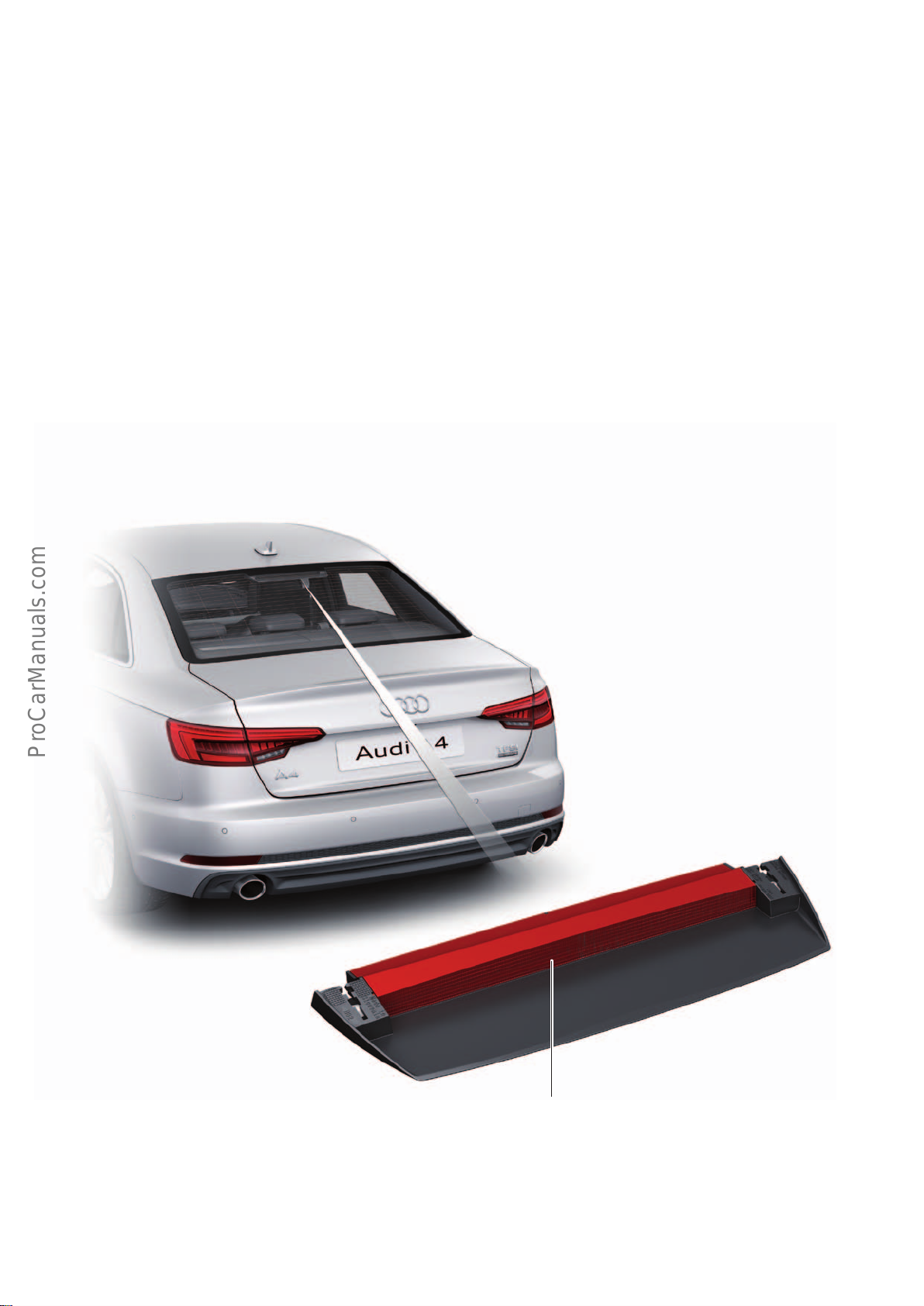
High-level brake lights / number plate lights
< Back
Forward >
Ξ Contents
Activation
As with the number plate light, the high-level brake light is activated by the central control unit for comfort/convenience system
J393.
High-level brake lights
AudiA4saloon
The high-level brake light of the saloon model is located inside the
vehicle behind the rear window. 18LEDs with a power output of
4watts support the brake light function.
In the event of a fault, the complete high-level brake light must be
replaced.
The high-level brake light and the number plate lights stay activated even the when luggage compartment flap is open.
If the AudiA4saloon has so-called "privacy" glazing, 18LEDs with
a power output of 11watts are used to compensate for the light
absorbed by the tinted glass.
646_075
High level brake light bulb
M25
54
Page 55
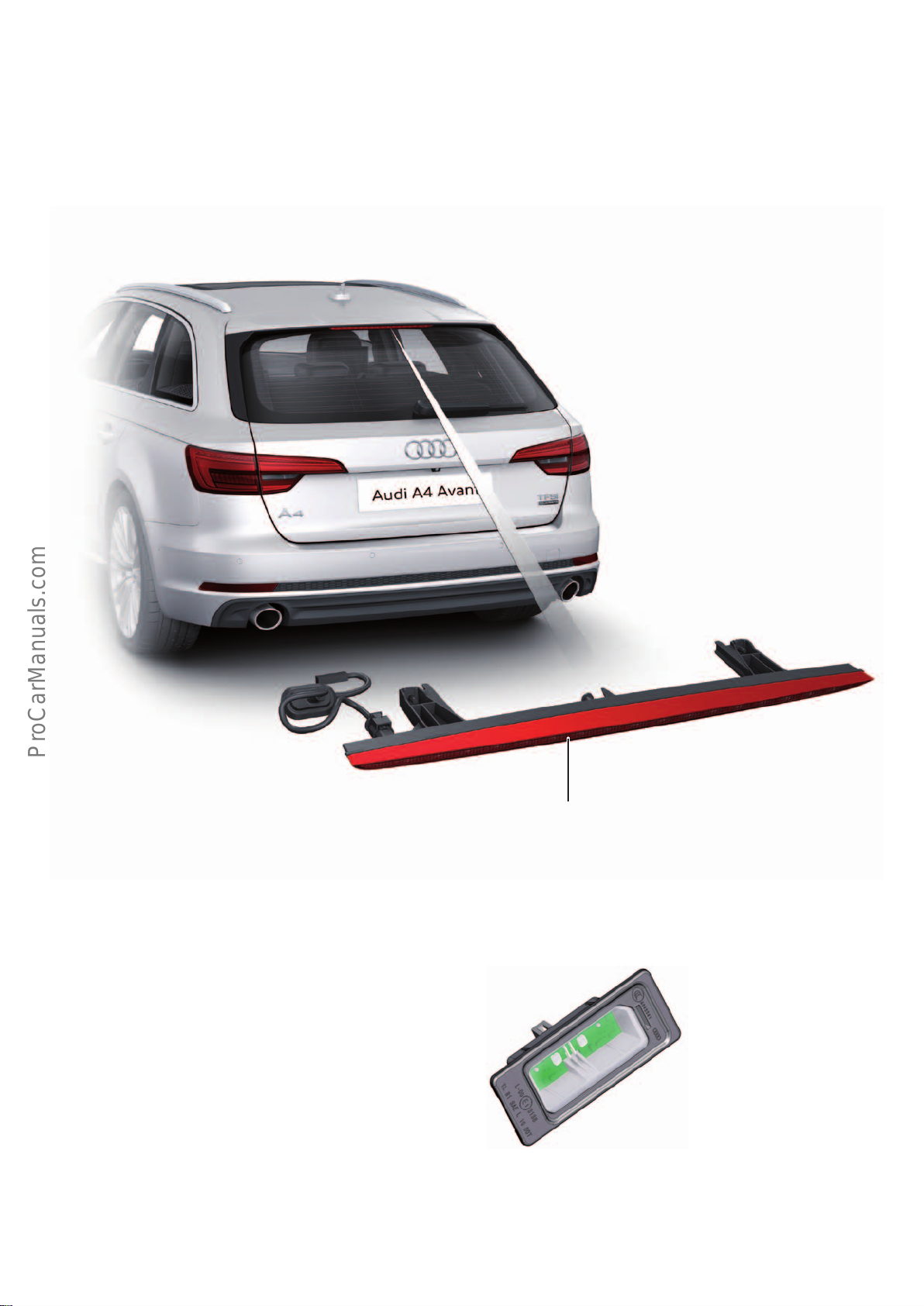
AudiA4Avant
< Back
Forward >
Ξ Contents
In the Avant model, the high-level brake light is integrated in the
rear spoiler. The 18LEDs have a power output of 4watts.
In the event of a fault, the complete high-level brake light must be
replaced.
Number plate lights
The number plate lights on the Audi A4 use LED technology irrespective of tail light version. Each of the 2 number plate lights is
clipped into the luggage compartment flap panel and has 2 LEDs.
646_076
High level brake light bulb
M25
646_077
55
Page 56
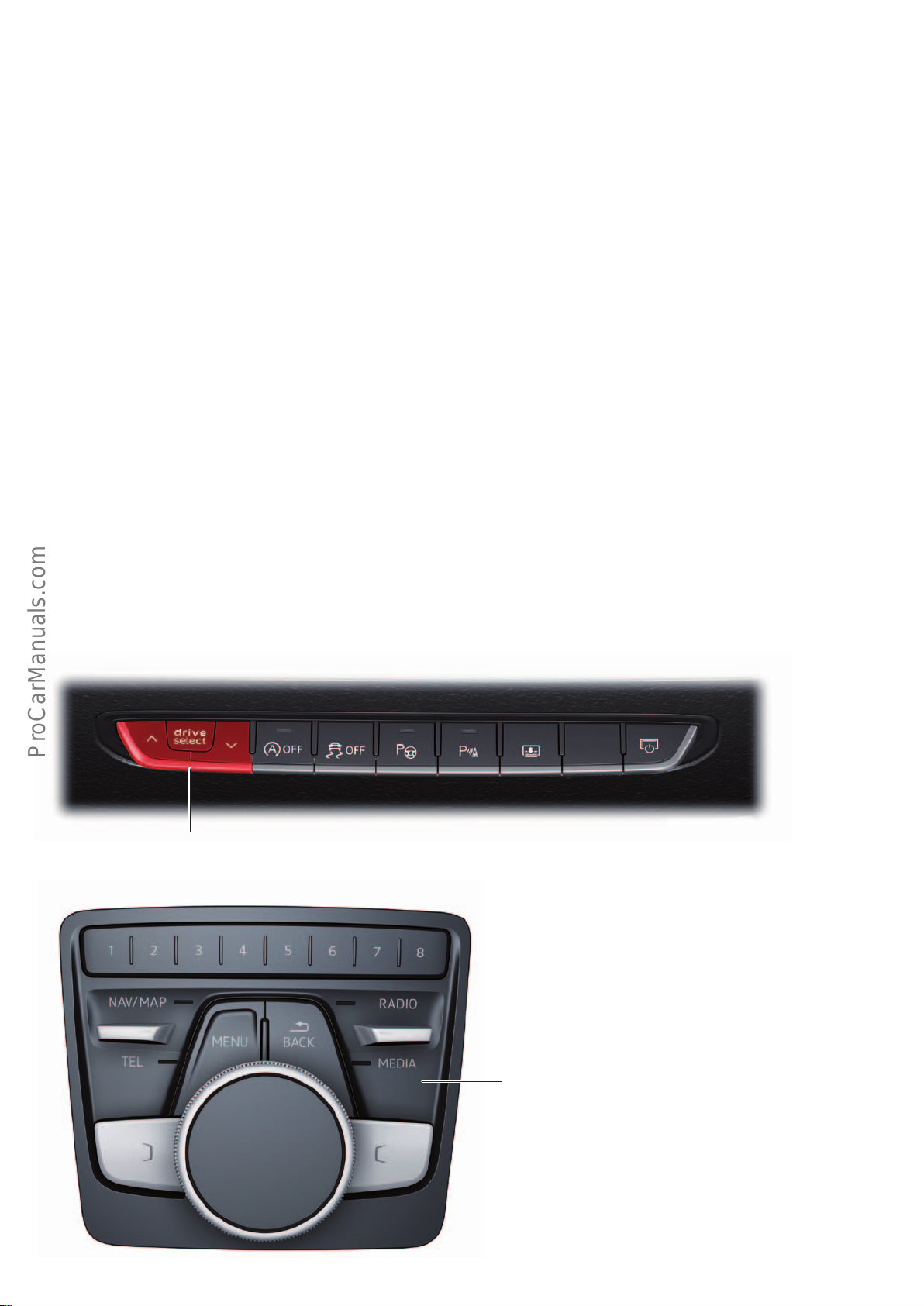
Audi drive select
< Back
Forward >
Ξ Contents
Functional characteristics
The AudiA4 is equipped with Audi drive select.
With Audidrive select, it is possible to modify the vehicle characteristic. The mode can be changed when the car is stationary or
while driving. Condition: "Terminal 15 on".
In the Audi A4 (type 8W), the driver can select between the following drive modes:
• eciency
• comfort
• auto
• dynamic
• individual
Displays and operation
The Audidriveselectsystem can be configured either using the
Audidriveselect button in operating unit 1 for drive and comfort/
convenience functions E791 in the centre console or using the
multimedia systemoperating unit E380.
In any case, the power steering and the engine characteristic are
aected.
Audi drive select also aects the following equipment:
• Automatic gearbox
• Sport dierential
• Air conditioning system
• Cornering light
• Ambient lighting
• Dynamic steering
• Damper control
• Cruise control system
• unit 2
• Audipresensebasic / presensecity
• Start-stop system
Depending on the equipment specification, the drive mode can
also be selected on the multifunction steering wheel. In the
AudiA4, the options menu is displayed on the MMI screen or in the
instrument cluster.
Operating unit 1 for drive and comfort/convenience functions
E791
646_078
Multimedia system control panel
E380
646_079
56
Page 57

Audi drive select function
< Back
Forward >
Ξ Contents
The following systems are, among others, influenced by drive
select:
System Vehicle characteristic
Engine and automatic gearbox
Steering The steering can be adapted with the regard to steering assistance. A distinction is made here between
Dynamic steering The following applies to models with dynamic steering:
Damper control Audidriveselect allows the damper control system to be configured for sporty (dynamic), comfort-oriented
Cornering light The cornering light adapts the main beam to the curvature of the corner in a speed-responsive manner. The
Air conditioning
system
Depending on mode, the engine and automatic gearbox react to accelerator inputs in a more spontaneous or
more balanced way. In the sporty dynamic mode, the gear shift points are adjusted to higher up the rev
band. When the vehicle is running in eciency mode, on the other hand, the shift points (automatic gearbox)
are adjusted to lower down the rev band in order to save fuel.
3characteristics ranging from comfortable (comfort) and balanced (auto) to sporty (dynamic).
To minimise steering eort for the driver, the steering ratio is adjusted to the speed at which the vehicle is
travelling. At higher speeds, the steering is configured for less sensitivity in order to improve handling. At
lower speeds, the steering is more direct in order to minimise steering eort for the driver during manoeuvring, for example. In addition, the dynamic steering system provides a more agile steering response at low
and medium speeds.
(comfort) or balanced (auto) response.
swivelling action of the lights and beam strength are also adapted to the mode.
The air conditioning system is only aected in eciency mode, when it operates in a highly fuel-ecient
way.
Cruise control
system
Adaptive cruise
control (ACC)
Sport dierential In comfort mode, activation of the sport dierential is kept at a minimum. Primarily, load-change reactions
The cruise control system is only aected in eciency mode, when it operates in a highly fuel-ecient way.
Depending on drive select mode, the acceleration response options range from comfortable (comfort) to
sporty (dynamic). Accordingly, the adaptive cruise control also reacts to the driving style of the driver in front
in a more balanced or more spontaneous way. The eciency mode chooses a set-up for maximum economy.
are eectively damped so that the car has a very balanced response.
In auto mode, the sport dierential is configured for optimal handling dynamics. The car steers very responsively through corners.
In dynamic mode, the sport dierential is at its most noticeable. The dynamic handling has distinctly sports
feel.
Functional features
• The vehicle remembers the last selected mode and the indi-
vidual mode configuration when it is restarted.
• To active the newly selected mode for the engine, too, the
accelerator must be briefly released (idle position) or briefly
pushed down into the full throttle position.
• To activate the newly selected mode for the steering as well,
the steering wheel must also be moved into the straight-ahead
position (zero position).
• The following applies to models with an automatic gearbox: In
dynamic mode, gearbox positionS is automatically selected. In
eciency mode, gearbox positionE is automatically selected.
• The eciency mode is unavailable when towing a trailer.
• The following applies to models with a manual gearbox: if the
accelerator is pressed down fully beyond the point of resistance
at full throttle in eciency mode, engine power output is
automatically adjusted to provide maximum acceleration.
• On some models, maximum speed is only achieved in auto and
dynamic modes.
• The start-stop system is generally activated when the vehicle is
running in eciency mode.
57
Page 58
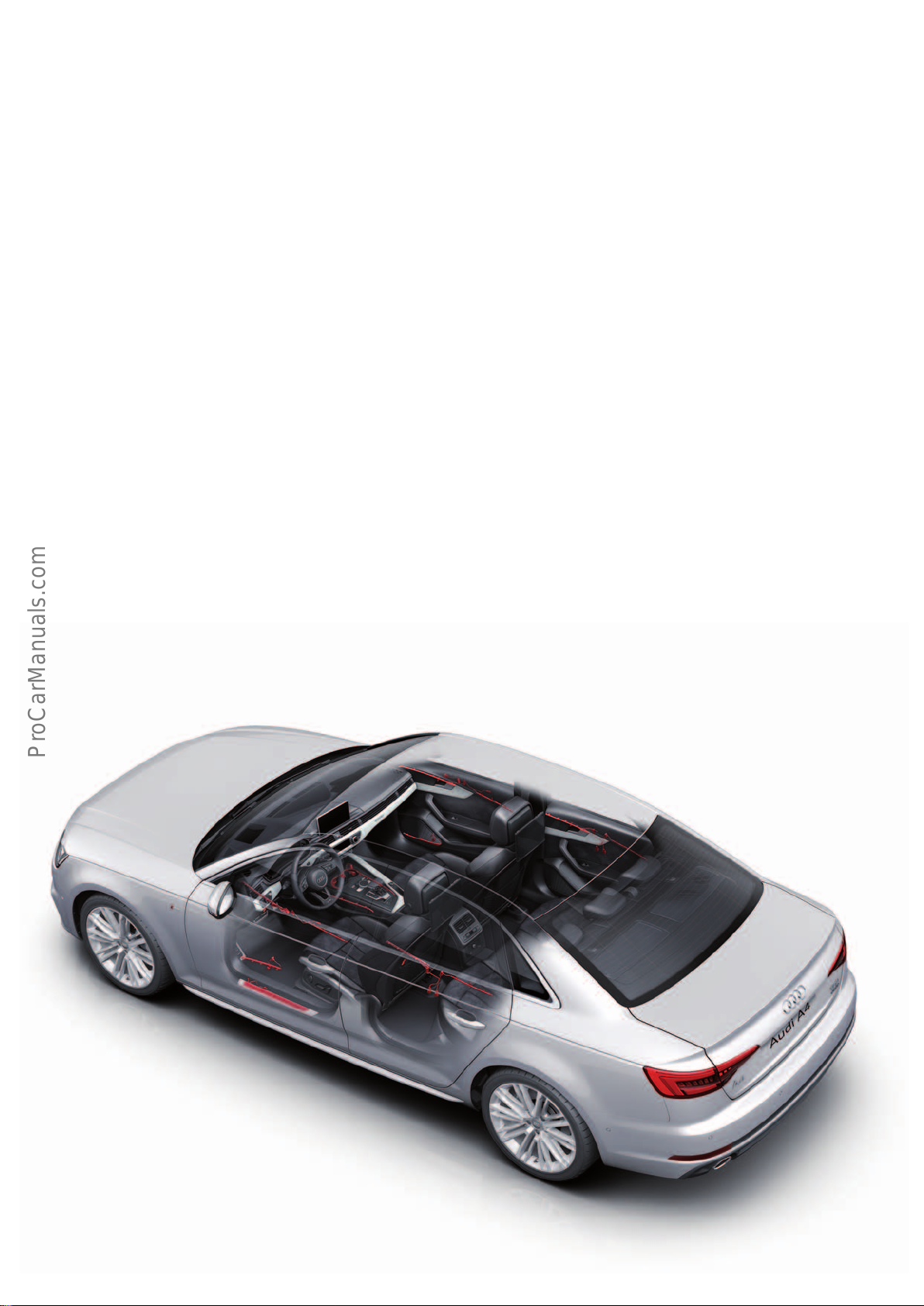
Vehicle electronics
< Back
Forward >
Ξ Contents
Interior lighting
As with the AudiQ7(type4M), the interior lighting in the
AudiA4(type8W) subdivided into 3production numbers depending on trim level:
• QQ0 basic interior lighting package
• QQ1 lighting package
• QQ2 background lighting
QQ0
Glove compartment lighting, luggage compartment lighting
The glove compartment lighting in the AudiA4(type8W) is the
only lighting which uses conventional bulbs/lamps.
QQ1
Vanity lights, footwell lights, cupholder light, centre console
background lighting, entry light, door panel lighting in the door
trims and door inner handle lighting
White light and LED technology are exclusively used as light
sources.
QQ2
Contour lighting in the door trim, door pocket lighting.
The LEDs are coloured. 30 light colours are available. The door
pocket lighting in the AudiA4(type8W) is non-capacitive. An
exception is the LED in the door inner handle which lights up in
white only.
The list of interior lighting features with the various production
numbers always includes the equipment with lower production
numbers.
The background lighting QQ2 is controlled by a background lighting module. The background lighting module is a software function
and is integrated in the electrical system control unit J519.
J519 is the RGB master. RGB denotes the colours red, green and
blue. The colour profiles are produced by additive mixing of these
colours. In the case of additive colour mixing, the human eye is
able to discern multiple wavelengths simultaneously and in quick
succession, but the dierent colours cannot be resolved and
appear as a single colour to the eye.
Apron lighting
In the AudiA4(type8W), the apron lighting is provided by 2LEDs
per door. These LEDs also function as door handle lights. In the
new AudiA4Avant, a single light is integrated in the rear hatch as
apron lighting and illuminates the area in front of the luggage
compartment when the rear hatch is open.
646_004
58
Page 59
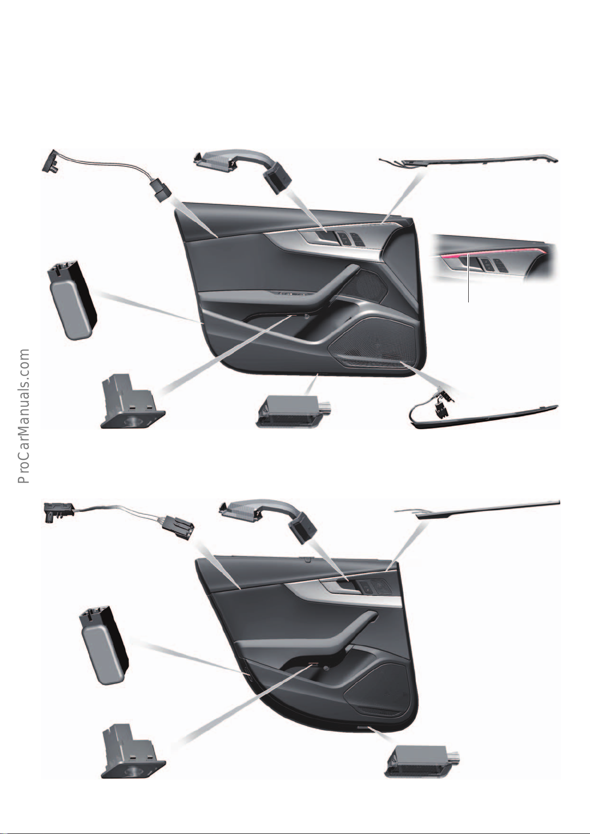
Interior door trim lighting
< Back
Forward >
Ξ Contents
Background lighting as shown using the door trims as an example
–the door warning light is passive, but may use a conventional
bulb/lamp depending on country.
Front door trim
Door panel lighting
Door warning light (passive)
Inner door handle light Contour lighting
In the case of the exterior lighting, the apron lighting is integrated
in all 4 door handles in conjunction with PR nos. QQ1 and QQ2.
Unlike the AudiQ7(type4M), the door pocket lighting is not
capacitively controlled.
Exit warning
(with optional assistance system)
Door pocket lighting
Rear door trim
Door panel lighting
Door warning light (passive)
646_005
Speaker lightingEntry light
Inner door handle light Contour lighting
Door pocket lighting
646_006
Entry light
59
Page 60
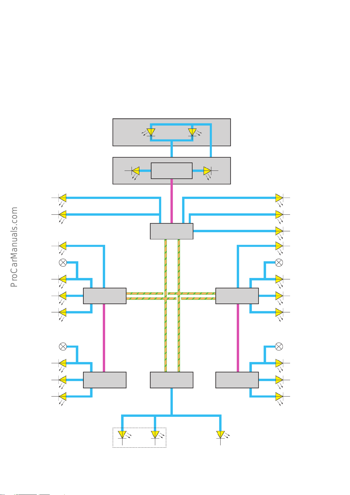
Function and control unit architecture
< Back
Forward >
Ξ Contents
Interior and background lighting
The LEDs of the interior and background lighting are controlled by
various control units which are networked with one another via the
convenience CAN. These are:
• Electrical system control unit J519
• Central control unit for comfort/convenience system J393
• Driver side door control unit J386
• Front pass. side door control unit J387
WX2
Rear left reading
light
WX3
Front left reading
light
Vanity light, left/
right
Glove box
The following control units connected by LIN bus are also used:
• Door control unit, rear driver side J926
• Rear passenger side door control unit J927
• Roof electronics control unit J528
• Front overhead module WX3
• Interior light, rear centre WX2
Rear right reading
light
J528
LIN2
Front right reading
light
Front footwell light
Rear footwell light
Apron lighting
Door warning
1)
light
Entry light
Inner door handle
Speaker
Door warning
1)
light
Entry light
Inner door handle
Apron lighting
J386
2)
LIN
J926
J519
Convenience CAN
J393
J387
2)
LIN
J927
Storage
compartment
Apron lighting
Door warning
1)
light
Entry light
Inner door handle
Speaker
Door warning
1)
light
Entry light
Inner door handle
Apron lighting
1)
Country-dependent, otherwise passive
2)
Door control unit LIN bus
3)
AudiA4Avant only
60
Luggage compartment
Apron lighting
Rear hatch
3)
646_007
Page 61
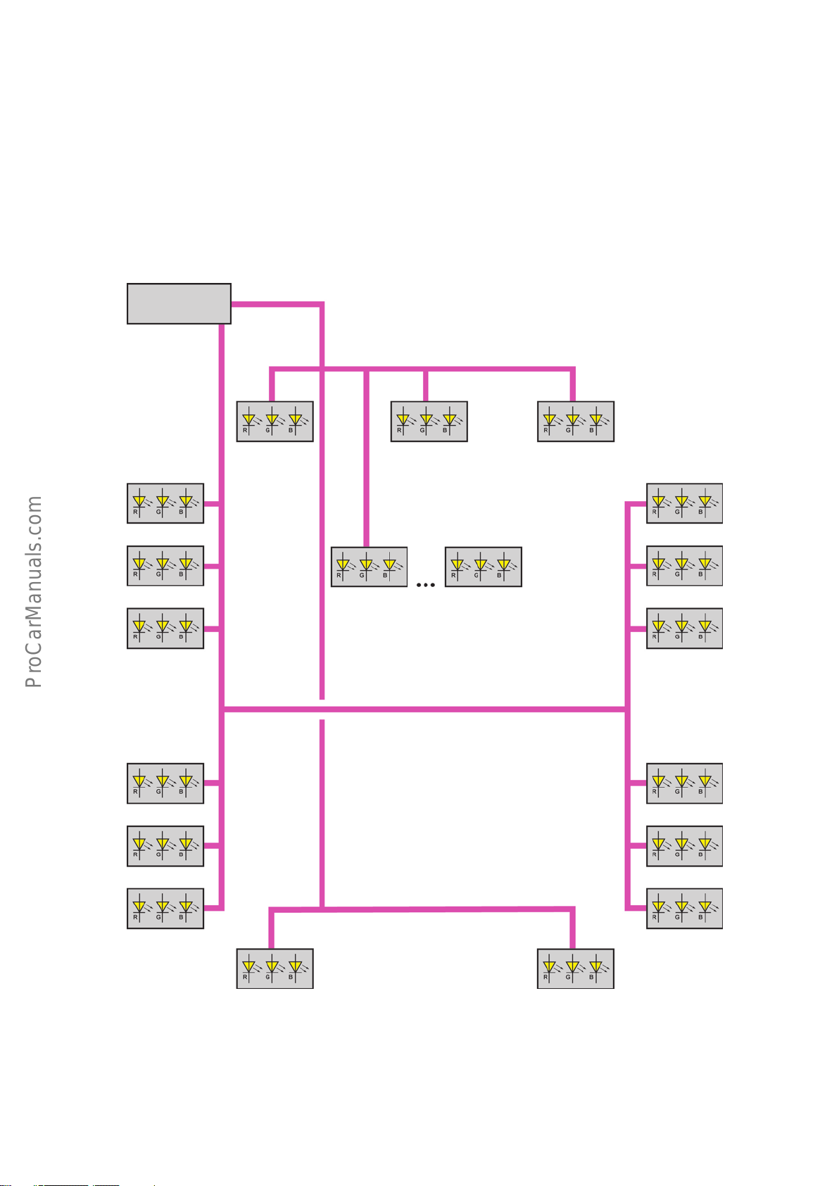
RGB components
< Back
Forward >
Ξ Contents
The RGB components of the background lighting are controlled by
the electrical system control unit J519. The individual LEDs or
optical fibres are supplied via 2 LIN bus lines.
J519
LIN5
Door shoulder
Speaker
Door pocket
LIN6
Footwell Cupholder
Centre console
Footwell
Door shoulder
Speaker
Door pocket
Door shoulder
Speaker
Door pocket
Footwell Footwell
Door shoulder
Speaker
Door pocket
646_008
61
Page 62
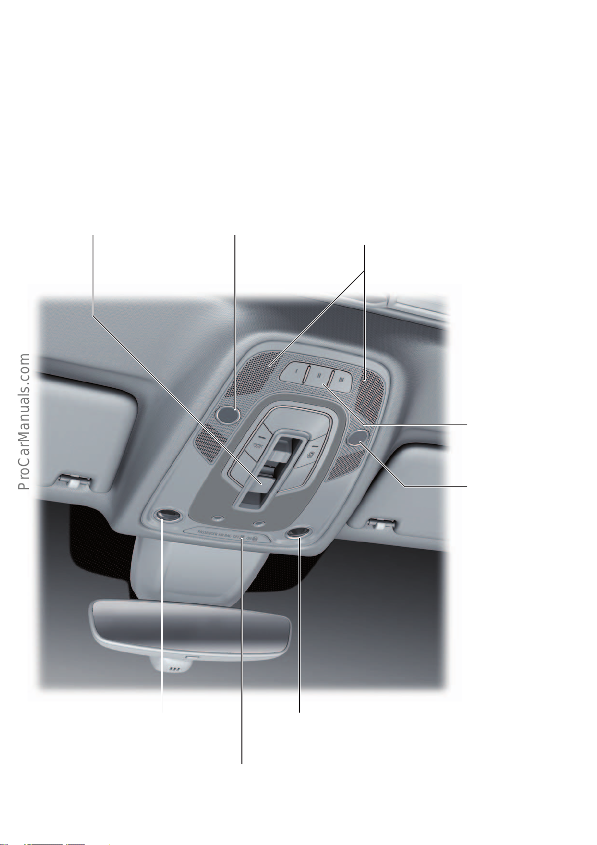
Overhead module
< Back
Forward >
Ξ Contents
The overhead module is used to activate and read in the following
components:
• Roof electronics control unit J528
• Sliding sunroof operating button
• Garage door operating unit E284
• Front interior lights
• Hands-free telephone microphone
• Front passenger airbag OFF warning lamp K145
Sliding sunroof operating button
Microphone
The interior lights are capacitive, i.e. they are controlled by touch.
The interior lights use LED technology.
The roof electronics control unit J528 is a LIN subscriber of the
electrical system control unit J519.
Motion detectors of the interior monitoring system
integrated in the anti-theft alarm
Garage door operating unit
E284
Microphone
646_009
62
Interior light
Interior light
Passenger airbag OFF warning lamp
K145
Page 63
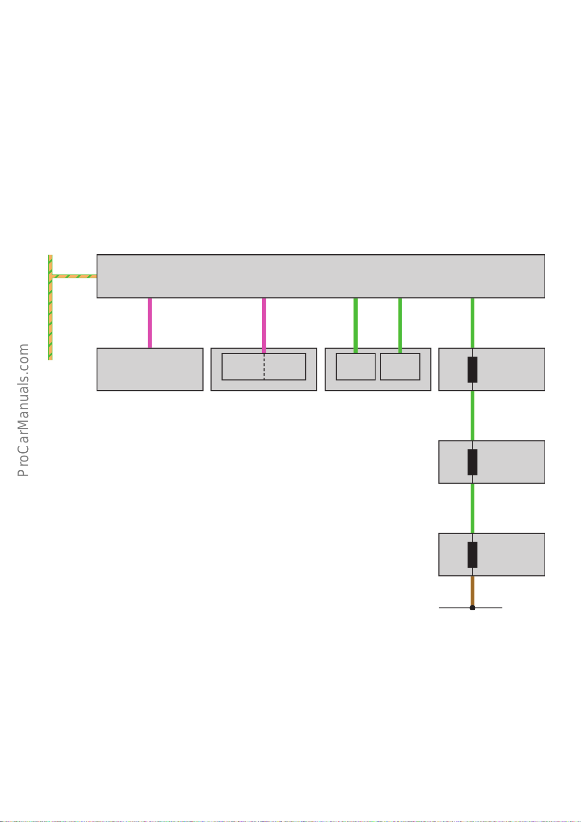
Anti-theft alarm
< Back
Forward >
Ξ Contents
The anti-theft alarm of the AudiA4(type8W) is largely identical to
the systems used in current Audi models.
The windows in the rear compartment of the AudiA4Avant are
also equipped with glass breakage sensors.
The anti-theft alarm sensor G578, which comprises the interior
monitoring sensor G273 and the vehicle inclination sensor G384,
and the alarm hornH12 are LIN bus subscribers of the central
comfort/convenience system control unit J393. G578 and H12 are
connected to J393 via dierent LIN bus lines.
J393
Convenience CAN
LIN1
H12
LIN2
G273
G384
G578 V53
A new feature of the AudiA4 and its derivatives is that the alarm
(if activated) trips if the vehicle control units are accessed via the
diagnostic connector T16 or via the on-board diagnostics (OBD).
F124F123
G304
1)
Key:
F123 Rear hatch contact switch for anti-theft alarm
F124 Key contact switch in lock cylinder, anti-theft alarm system,
central locking system
G183 Glass breakage sensor for rear left side window
G184 Glass breakage sensor for rear right side window
G273 Interior monitoring sensor
G184
G183
Ground
G304 Glass breakage sensor for rear window
G384 Vehicle inclination sensor
G578 Sensor for anti-theft alarm system
H12 Alarm horn
J393 Central control unit for comfort/convenience system
V53 Central locking motor in rear hatch
1)
1)
646_045
1)
AudiA4Avant only
63
Page 64
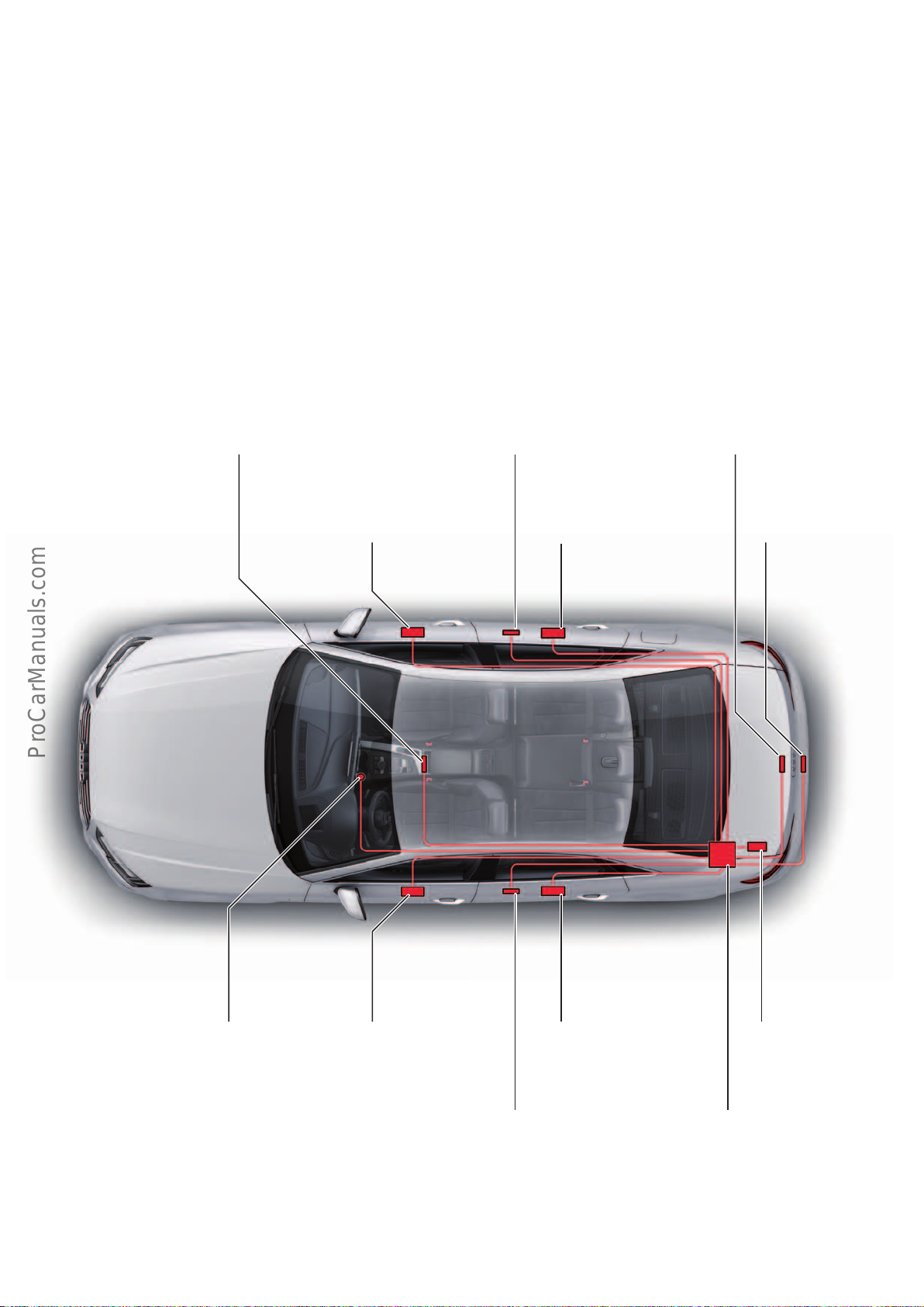
Central locking
< Back
Forward >
Ξ Contents
The vehicle can be centrally locked and unlocked in various ways:
• Using the remote control key
• Via the sensors in the door handles (advanced key)
• Manually via the locking cylinder in the driver's door
• Using the inner central locking switch (door trim)
Components
Interior aerial 1 for entry and
start authorisation
R138
Front pass. side
door control unit
J387
In the case of the AudiA4, the door handle sensors are used for
locking and unlocking with the advanced key. The door handle
sensors are not deactivated after 72h. This is no longer necessary
due to the very low static current.
Aerial for entry and start
authorisation, right
R201
Door control unit,
rear pass. side
J927
Luggage compartment aerial for
entry and start authorisation
R137
Locking button in
the rear hatch
E806
Entry and start authorisation control unit
E408
Driver side door
control unit
J386
Door control unit,
rear driver side
J926
Aerial for entry and start
authorisation, left
R200
646_065
Rear hatch power
opening control unit
J938
Central control unit for
comfort/convenience
system
J393
64
Page 65
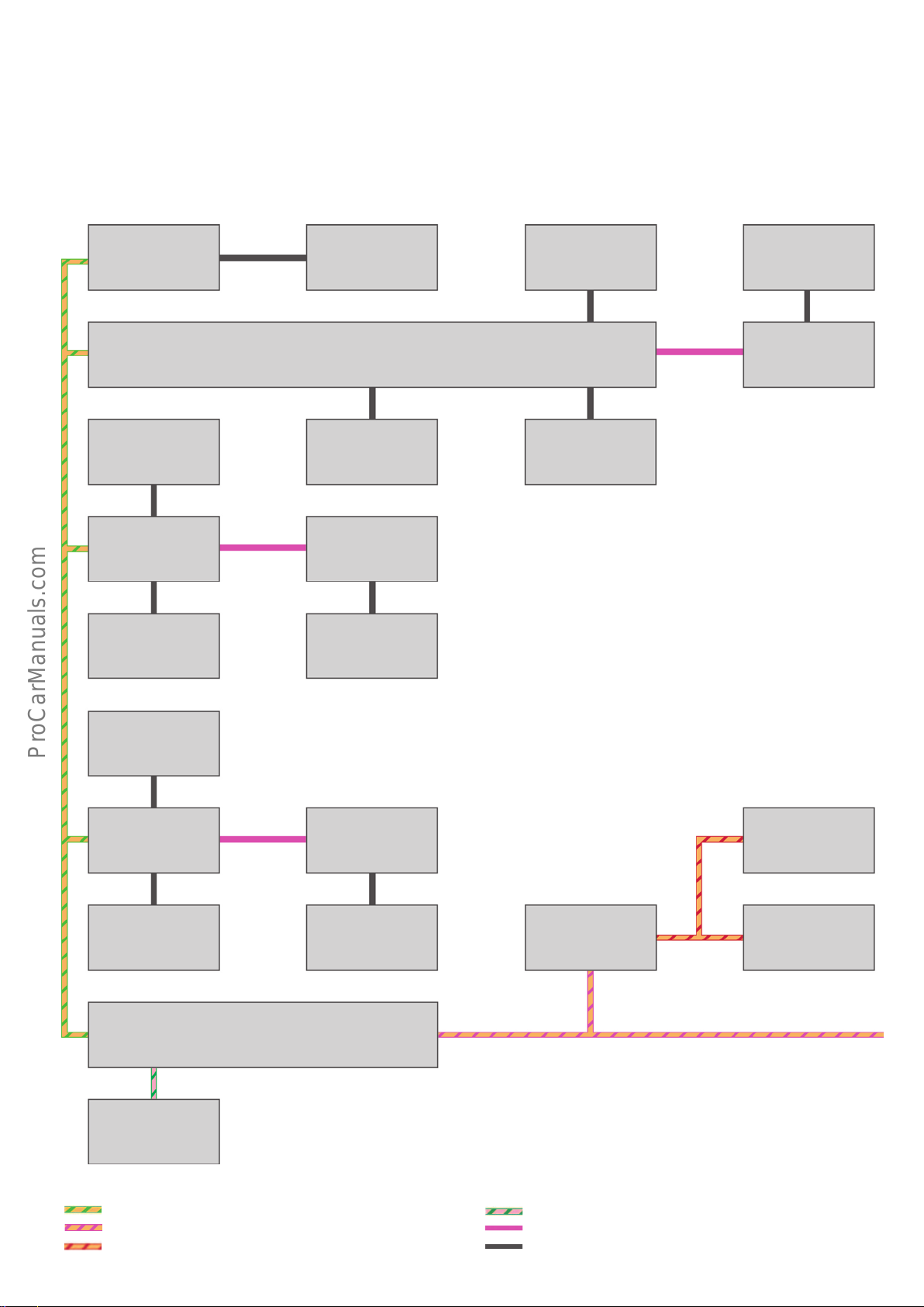
System overview
< Back
Forward >
Ξ Contents
The system overview shows the theoretical maximum specification. The ABScontrol unit J104 receives the vehicle speed signal
required for the Autolock function via the central control unit for
comfort/convenience system J393.
Rear hatch
control unit
J605
Central control unit for comfort/convenience system
J393
Interior locking button,
driver side
E308
Driver side
door control unit
J386
Locking button in the
rear hatch
E806
Tank flap remote
release switch
E204
Door control unit,
rear driver side
J926
All personalised settings are visualised on the MMI displayJ685.
The exterior door handle contact sensors in all 4 doors are connected directly to the central control unit for comfort/convenience
system J393.
Rear hatch handle
release button
E234
Exterior door handle
contact sensors
G415–G418
Rear hatch opening
sensors 1 and 2,
in rear bumper
G750, G760
Rear hatch power opening control unit
J938
Exterior door handle
touch sensor, driver side
G415
Interior locking button,
front pass. side
E309
Front pass. side
door control unit
J387
Exterior door handle
touch sensor,
front passenger side
G416
Data bus diagnostic interface
J533
Exterior door handle
central locking button,
rear left door
E371
Door control unit,
rear pass. side
J927
Exterior door handle
central locking button,
rear right door
E372
Information electronics
control unit 1
J794
MMI display
J685
Multimedia system
operating unit
E380
ABS control unit
J104
Key:
Convenience CAN
Infotainment CAN
Modular Infotainment Platform (MIB) CAN
646_066
FlexRay
LIN bus
Discrete cable
65
Page 66
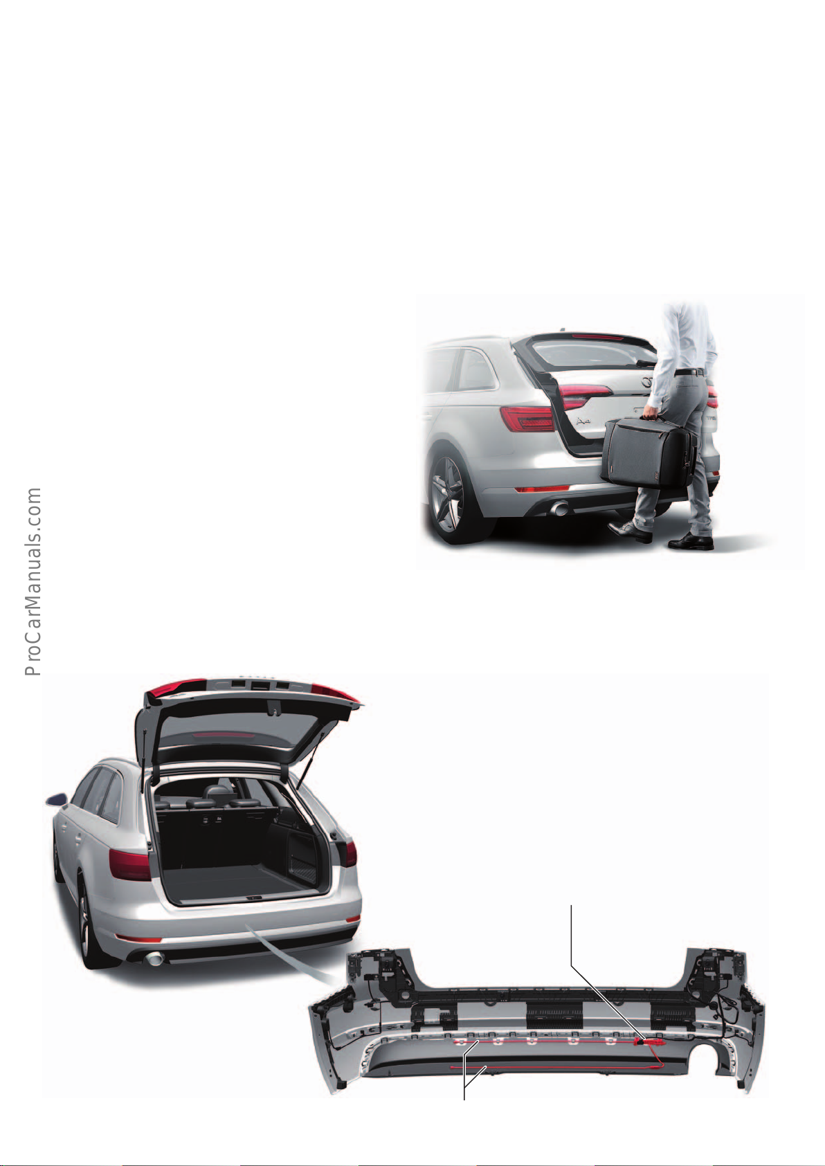
Sensor-controlled luggage compartment release
< Back
Forward >
Ξ Contents
The "sensor-controlled luggage compartment release" option is
only available in combination with the "advanced key" option. A
further requirement for opening and closing the rear hatch is that
the car key is within the detection range of the luggage compartment aerial for entry and start authorisation R137.
The rear hatch of the Audi A4 can only be opened with a foot
gesture.
Starting scenario
Stand about 20 cm behind the rear end of the vehicle and then
perform a simple swipe of the foot and shin as closely as possible
to the bumper. The shin must be within the upper range of the
sensor and the foot within the lower range of the sensor. Quickly
retract the foot and shin so that both are outside the range of the
sensor.
Closing of the rear hatch is annunciated by a warning signal and
can be interrupted by repeating the movement described above.
The rear hatch of the AudiA4Avant can be opened or closed with a
foot gesture.
The vehicle is not locked when the rear hatch is closed with a foot
gesture.
There are also twin buttons in the luggage compartment: one
button for closing the rear hatch only and one button for locking
the vehicle. In addition, the driver can close the rear hatch using
either the button in the door or the advanced key (hold down).
Design
The sensor line of the sensor-controlled luggage compartment
release system consists of 2 coaxial wires.
646_067
Rear hatch power opening control unit
J938
66
Sensor line
646_068
Page 67
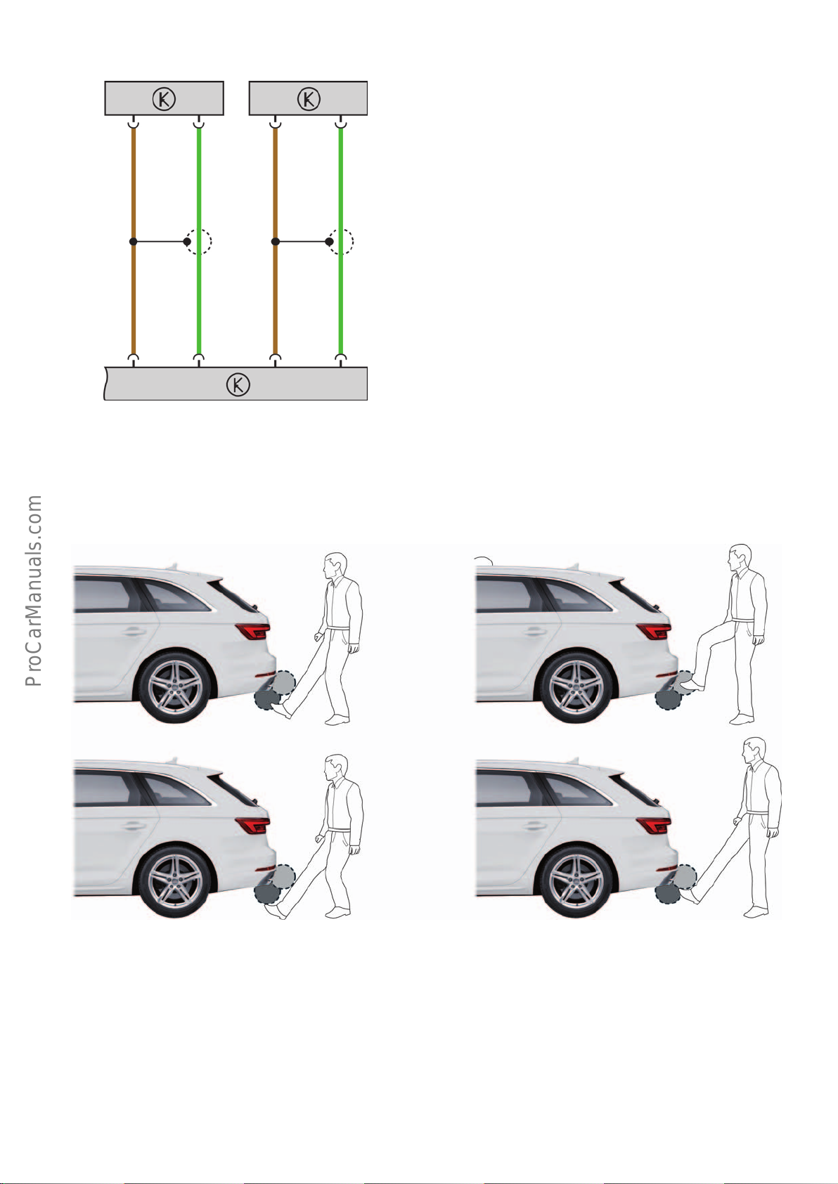
Activation
< Back
Forward >
Ξ Contents
G750 G760
5
1
J938
Potential operating errors
detect both sensor lines (induction loops).
Key:
G750 Rear hatch power opening sender, in rear bumper
G760 Rear hatch power opening sender 2, in rear bumper
J938 Rear hatch power opening control unit
1 Sensor-, G750
2 Sensor+, G750
3 Sensor-, G760
5
4 Sensor+, G760
5 Shield
432
646_070
The leg must be reliably detectable by both grey detection areas.Potential operating errors usually occur when the system fails to
Other possible errors
The sensor-controlled rear hatch is not available or only available
to a limited extent in the following situations (examples):
• If the rear bumper is very dirty.
• If the rear bumper is wetted with salty water, e.g. after
driving on gritted roads.
critical
646_069
• If the luggage compartment lid is closed or opened directly
beforehand.
67
Page 68
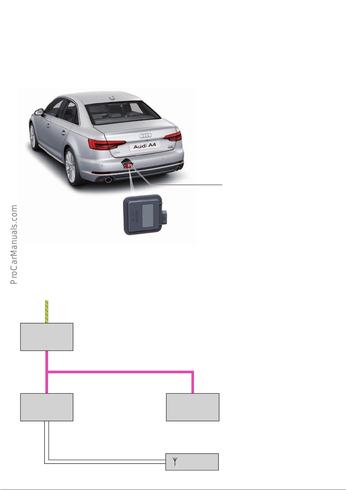
Garage door opener (HomeLink)
< Back
Forward >
Ξ Contents
Installation locations
The garage door opener control unitJ530 is attached to the vehicle
body at the rear left by means of a bracket specific to the AudiA4.
The control unit itself is a carry-over part from the AudiQ7(type4M).
The garage door opener programming aerial R278 for programming the handheld garage door sensor terminates inside the
AudiA4 (within the cable duct in the rear right heel panel area).
Garage door opener control unit
J530
System architecture
The electrical system control unit J519 the master control unit for
garage door operation control unit J530. The control unit J530
communicates with control unit J519 via LIN bus (LIN 2). The same
applies to the garage door operating unit E284 (integrated in
overhead module).
Convenience CAN
Electrical system
control unit
J519
LIN2
646_046
The garage door opener programming aerial R278 is connected to
garage door operation control unit J530. The garage door opener
programming aerial R278 is configured as a dipole antenna.
Garage door
operation control unit
J530
68
Garage door
operating unit
E284
Garage door opener
programming aerial
R278
646_048
Page 69
Programming process
< Back
Forward >
Ξ Contents
As with the AudiQ7(type4M), there are two dierent processes
for programming both garage door opener systems for the new
AudiA4:
• a fixed code system
• a rolling code system
Both programing processes are MMI-controlled. The individual
steps are visualised on the MMI screen.
Vehicle settings
Program garage door opener
Clear programmed settings
Garage door opening
646_049
The two code systems are handled dierently. A programmed fixed
code system is ready for use straight after programming. In the
case of a rolling code system, on the other hand, the garage door
and the in-car HomeLink system, for example, still need to be
synchronised.
Service measurement data / diagnostic tester
The last 3 programming cycles of the sensor can be read out by
service personnel via the data blocks.
These 3 data blocks provide the mechanic with the following
information relating to the last 3 programing cycles:
• Frequency
• Manufacturer
• Fault status and modulation
• Programming timeout
• User abort
Other data blocks provide the mechanic with information about
the current country code and the system supply voltage.
• Speed information
• Aerial
• Status
• Channel
Note
It is recommended that two persons perform the adaption process, e.g. to synchronise the garage door drive with the
HomeLink system, as there is usually only a very small window available for synchronisation, e.g. between the garage door
opener and the garage door itself.
Note
Individual buttons can be reprogrammed using the menu navigation. This overwrites the previously stored value.
All programmed channels can be deleted with menu assistance.
Programming can be aborted at any time using the BACK button.
69
Page 70
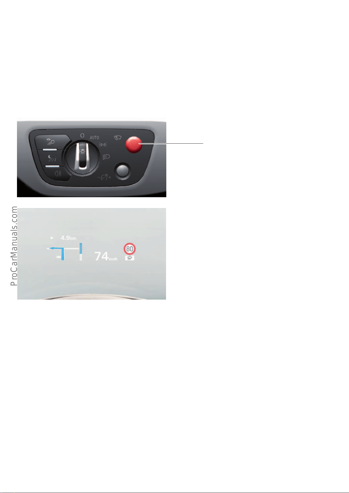
Head-up display
< Back
Forward >
Ξ Contents
Warnings, selected information from assistance systems and
navigation instructions can be projected onto the windscreen via
the head-up display (control unit for windscreen projection J898).
This information is displayed within the driver's field of vision. The
virtual image is only visible to the driver within a limited region of
the windscreen. The driver is able to discern a virtual image at a
distance of approximately 2.1 m (image viewing distance).
646_063
The control unit for windscreen projection J898 can be invoked via
the diagnostic tester using diagnostic code 82. J898 is integrated
in the vehicle electrics via the infotainment CAN.
The head-up display is attached to the module cross-member by
means of an adjustable bracket.
Windscreen projection button
E736
646_064
Example of a display on the head-up display
Operating and setting options for customers
• Switching the head-up display on/o
• Individual height adjustment of the projected image (on the
windscreen projection button E736, in the rotary light switch
module)
• Selection of information to be displayed (via MMI menu)
Setting options for service partners:
The control unit for windscreen projection J898 can be calibrated.
Calibration is necessary under the following conditions:
• The control unit for windscreen projection J898 has been
replaced.
• The windscreen has been removed and installed or replaced.
• Adjustment of display brightness level (via MMI menu)
• Image rotation to align the display with the horizontal (via
MMI menu)
• The event memory contains the entry
NO or INCORRECT BASIC SETTING / ADAPTION.
70
Page 71
Self study programmes
Ξ Contents
< Back
Forward >
For more information about the technology of the AudiA4, please
refer to the following self study programmes.
Appendix
SSP286 New Data Bus Systems –
LIN, MOST, Bluetooth
Order number: 000.2811.06.20
SSP 634 Audi Q7 (type 4M)
Onboard power supply and networking
Order number: A15.5S01.19.20
TM
SSP 459 Audi A8’10
Onboard power supply and networking
Order number: A10.5S00.63.20
SSP 638 Audi Q7 (type 4M)
Convenience electronics
Order number: A15.5S01.25.20
SSP644 Audi A4 (type 8W)
Order number: A15.5S01.28.20
SSP647 Audi A4 (type 8W)
Infotainment and Audi connect
Order number: A15.5S01.29.20
71
Page 72

Audi Vorsprung durch Technik
646
All rights reserved.
Technical specifications are
subject to change.
Copyright
AUDI AG
I/VK-35
[email protected]
AUDI AG
D-85045 Ingolstadt
Technical status 07/15
Printed in Germany
A15.5S01.31.20
 Loading...