

Page 1
Self Study Programme 644
For internal use only
Audi A4 (type8W)
Audi
Service Training
Page 2
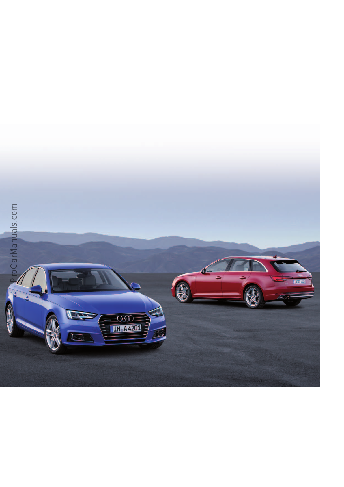
The A4 family and its predecessor the Audi 80 have been techno-
< Back
Forward >
Ξ Contents
logical innovators and true winners for many decades. The brand
with the four rings already set new standards for lightweight
construction, performance and agility with the first Audi 80 in the
year 1972. The brand’s longstanding bestsellers have always
played a major role at Audi. The new Audi A4 saloon and the new
Audi A4 Avant (type 8W) feature numerous high-end technologies
which set higher benchmarks for their class. They combine elegant
design with an innovative operating concept, systematic lightweight construction and new, ecient drivetrain solutions. The
Audi A4 saloon and Audi A4 Avant are also ahead of their peers in
terms of infotainment and assistance systems. As a result, Audi
drivers can look forward to a truly high-tech experience ― an
innovative synthesis of technology and aesthetics.
When it comes to aerodynamics, the two new models dramatically
outpace the competition. The AudiA4saloon has a drag coecient
of 0.23, while the Avant achieves 0.26. The rear design plays a
pivotal role in terms of aerodynamics. On the new Audi A4 saloon,
the lines of the rear hatch ensure that the air flow is smooth.
On the Audi A4 Avant, a roof edge spoiler with a strong downward
slant performs this function. When it comes to interior dimensions, the new Audi A4 saloon and the Audi A4 Avant surpass their
predecessors in almost every respect. All seats oer a feeling of
genuine spaciousness. The interior design underscores this impression, as its clear architecture is strictly focused on horizontal lines.
With the anatomically shaped front seats, the head restraints can
be adjusted not only for height, but also for distance from the
head. At market launch in Europe, the Audi A4 saoloon and the
A4saloon will be available with a choice of three TFSI and four TDI
engines. All engines comply with the Euro 6 emission limits, so
that the TDI has been labeled a clean diesel.
Manual gearboxes, S tronic and tiptronic, front-wheel drive and
quattro drive – there are various solutions for power transmission
in the new A4 models
Tailored technology is available for each engine.
Learning objectives of this self study programme:
This self study programme describes the design and functioning of
the AudiA4 (type8W). Once you have completed this self study
programme you will be able to answer questions on the following
topics:
644_002
• New features of the body
• New features of the occupant protection system
• Engines and fuel tank systems
• New power transmission features
• New chassis features
• Function of the surround camera
• New features of the air conditioning system
2
Page 3

Contents
Introduction
Presentation _________________________________________________________________________________________________________________________________________________ 4
Dimensions __________________________________________________________________________________________________________________________________________________ 6
Body
Introduction _________________________________________________________________________________________________________________________________________________ 8
Body structure _______________________________________________________________________________________________________________________________________________ 8
Attachments ________________________________________________________________________________________________________________________________________________12
Seating systems ____________________________________________________________________________________________________________________________________________14
Occupant protection
Passive safety _______________________________________________________________________________________________________________________________________________16
Active safety ________________________________________________________________________________________________________________________________________________23
Engines
Petrol engines ______________________________________________________________________________________________________________________________________________24
Diesel engines ______________________________________________________________________________________________________________________________________________26
Fuel tank ____________________________________________________________________________________________________________________________________________________28
SCR system _________________________________________________________________________________________________________________________________________________ 32
Engine/gearbox combinations ____________________________________________________________________________________________________________________________33
Power transmission
Overview ____________________________________________________________________________________________________________________________________________________ 34
6-speed manual gearbox 0DJ/0CS _______________________________________________________________________________________________________________________36
7-speed dual clutch gearbox 0CK/0CL – Stronic ________________________________________________________________________________________________________44
park-by-wire (PBW) parking lock _________________________________________________________________________________________________________________________48
8-speed automatic gearbox 0D5 – tiptronic _____________________________________________________________________________________________________________ 58
Gearbox functions __________________________________________________________________________________________________________________________________________60
Chassis
Overall concept _____________________________________________________________________________________________________________________________________________ 64
Axles and wheel alignment _______________________________________________________________________________________________________________________________ 65
Standard/sports suspension with electronic damper control (1BL/1BQ) ____________________________________________________________________________68
Brake system _______________________________________________________________________________________________________________________________________________ 71
Steering system ____________________________________________________________________________________________________________________________________________75
Adaptive Cruise Control (ACC) ____________________________________________________________________________________________________________________________ 79
Wheels and tyres ___________________________________________________________________________________________________________________________________________ 80
Electrical system
Installation locations of control units ___________________________________________________________________________________________________________________ 82
Topology ____________________________________________________________________________________________________________________________________________________84
Surround cameras __________________________________________________________________________________________________________________________________________86
Infotainment
Overview of versions _______________________________________________________________________________________________________________________________________92
Air conditioning
Introduction ________________________________________________________________________________________________________________________________________________94
Air conditioners ____________________________________________________________________________________________________________________________________________95
Auxiliary heating ___________________________________________________________________________________________________________________________________________96
Steering wheel heating ____________________________________________________________________________________________________________________________________96
Service
Inspection and maintenance ______________________________________________________________________________________________________________________________97
Self study programmes ____________________________________________________________________________________________________________________________________99
new automotive components or new technologies.
It is not a repair manual! Figures are given for explanatory purposes only and refer to the data valid at the
time of preparation of the SSP.
This content is not updated.
For further information about maintenance and repair work, always refer to the current technical literature.
NoteThe self study programme teaches a basic understanding of the design and mode of operation of new models,
Reference
3
Page 4
Introduction
< Back
Forward >
Ξ Contents
Presentation
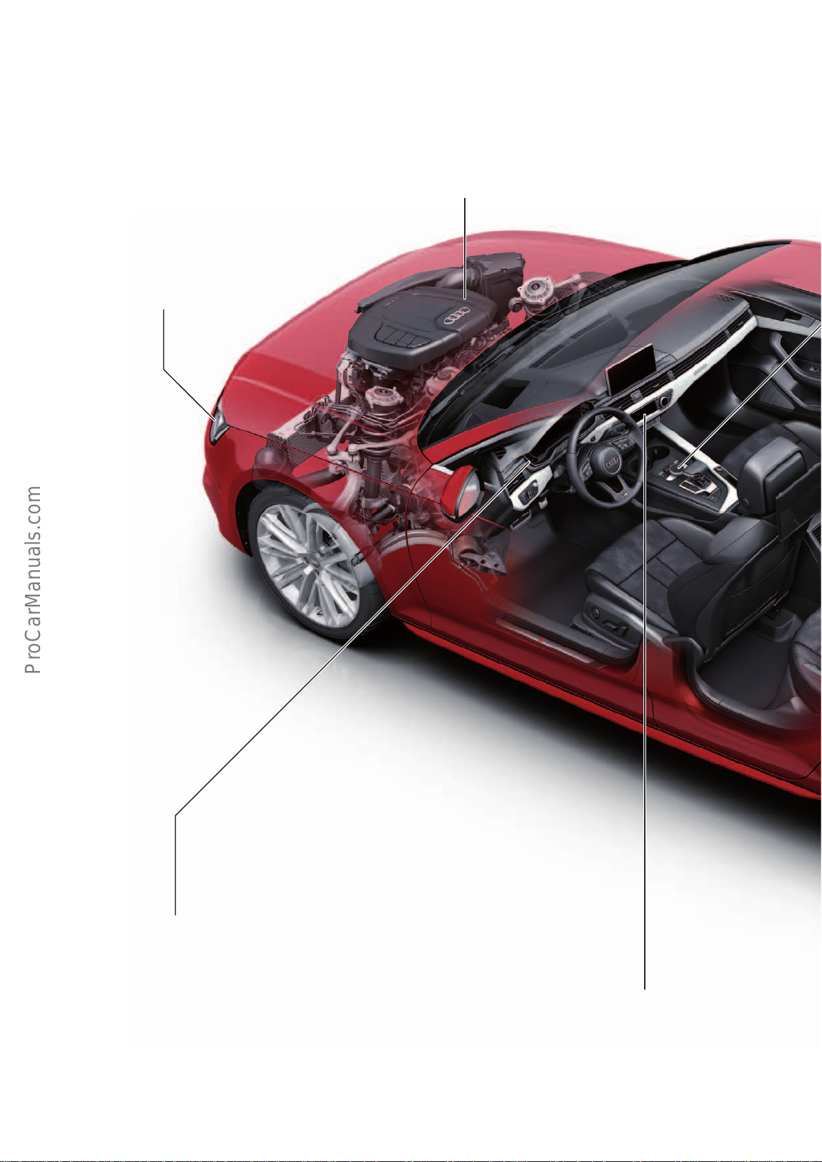
The new-generation Audi A4 is a fascinating synthesis of technology and aesthetics. All the technology in the brand's bestselling
family has been redeveloped so that it yet again defines the benchmark in the segment.
Headlights
Depending on trim level, the A4 can be equipped with
either xenon plus, LED or matrix LED headlight technology.
The dynamic turn signals use a series of light diodes
switched sequentially from inside to outside in the direction of turn, clearly signaling the car’s direction to other
road users.
Engines
• 1.4l R4 TFSI engine (110kW)
• 2.0l R4 TFSI engine (140–185kW)
• 2.0l R4 TDI engine (90–140kW)
• 3.0l V6 TDI (160–200kW)
Other engine versions will become available at a later date.
Assistance systems
The following systems are optionally available:
• adaptive cruise control Stop&Go including trac jam assist
• Predictive eciency assist
• Audi active lane assist
• Audi side assist
• Park assist
• Rear cross trac assist
• Exit warning
• Turning assist
• Evasion assist
• Camera based trac sign recognition
• Audi pre sense city, basic and rear
Air conditioning
Single-zone automatic air conditioning is standard. Just a few buttons and
dials are sucient for convenient control. Audi also oers the option of a
3-zone automatic air conditioning system whose temperature displays are
integrated into the rotary dials. When one of the capacitive rocker switches
is approached by a finger, its function is shown enlarged on the dark LCD
display and selected.
4
Page 5
Displays and operation
< Back
Forward >
Ξ Contents
Displays appear on a central MMI monitor which is permanently attached to
the instrument panel. The focal point of the operating system is the MMI allin-touch control unit with a full touch surface. Depending on trim level, the
Audi Q7 features a fully digital instrument cluster - the Audivirtualcockpit.
A head-up display is optional. The system projects relevant information onto
the windscreen in the form of easily comprehensible symbols and characters.
Body
In the Audi A4 saloon and A4 Avant, hot-stamped components form the
high-strength, crash-proof backbone of the occupant cell. They strengthen
the transition from the front end to the cabin, the frontal area of the roof
frame, the B posts, the side sills and parts of the floorpan.
The module cross member under the instrument panel is made of extruded
and sheet aluminium, while the front cross member is an extruded profile.
In addition, the nodes in the upper ends of the D posts are made of die-cast
aluminium and the rear hatch is also aluminium.
A sensor control for opening the luggage compartment, an electrical
luggage compartment cover and an electric drive for the rear hatch are available for the A4 Avant.
Power transmission
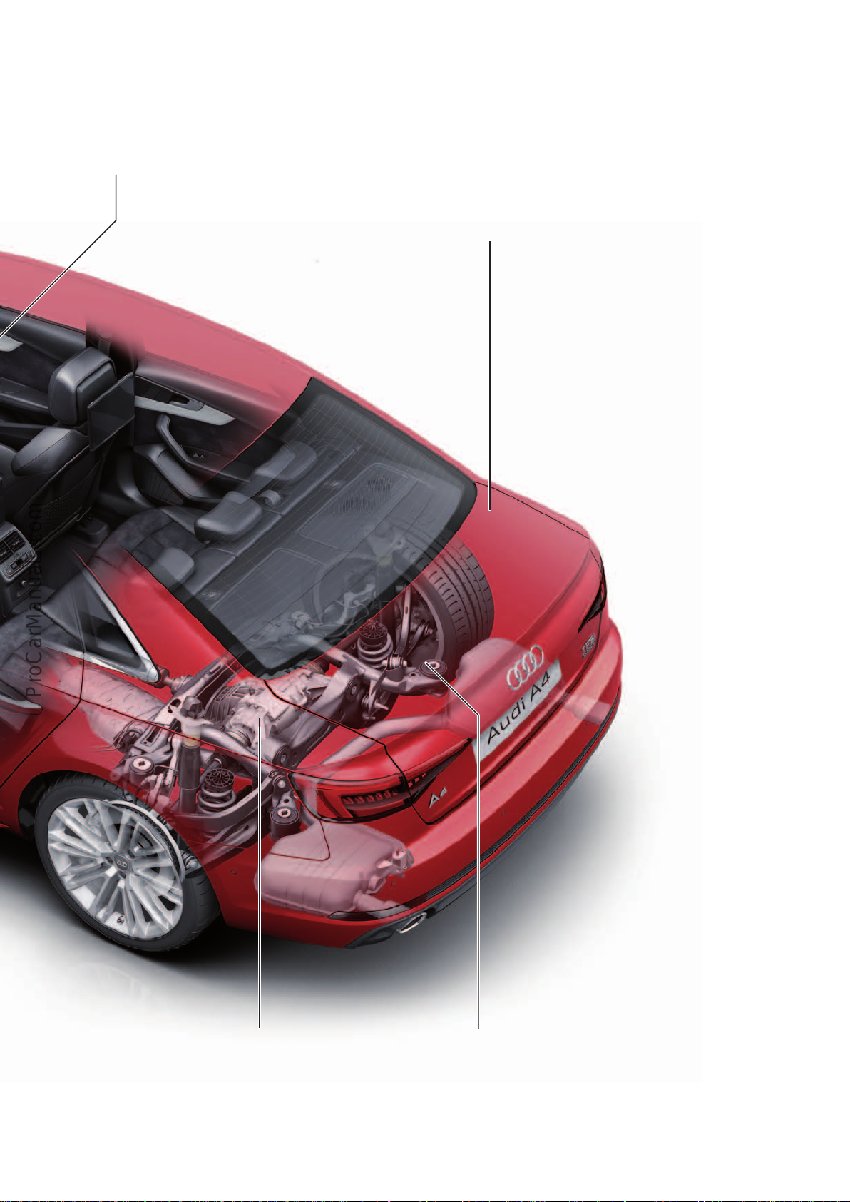
A newly developed eight-speed tiptronic transfers the engine's power to the
quattro full-time all-wheel drive system. Thare is also a 6-speed manual
gearbox or a 7-speed Stronic dual clutch gearbox with the option of frontwheel drive or quattro. The sport dierential, optional as of 2016, optimises
handling.
644_036
Suspension
The chassis is characterised by precise electro-mechanical steering in addition to the newly developed five-link front and rear axles. An additional
advantage is that driving dynamics can be adjusted to each situation. Audi
drive select influences the mapping of the power steering and accelerator
pedal as well as the optional variable suspension. A central suspension
control system has been applied to achieve ideal interaction between the
various driving dynamics systems.
5
Page 6
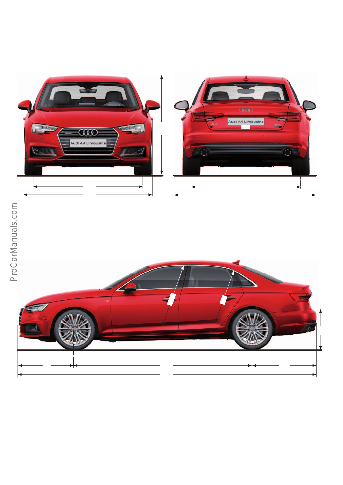
Dimensions
< Back
Forward >
Ξ Contents
1572
1842
644_047
1427
1
1039
985
1555
2022
644_048
953
684
880
6
2820
4726
1026
644_049
Page 7
2)
< Back
Forward >
Ξ Contents
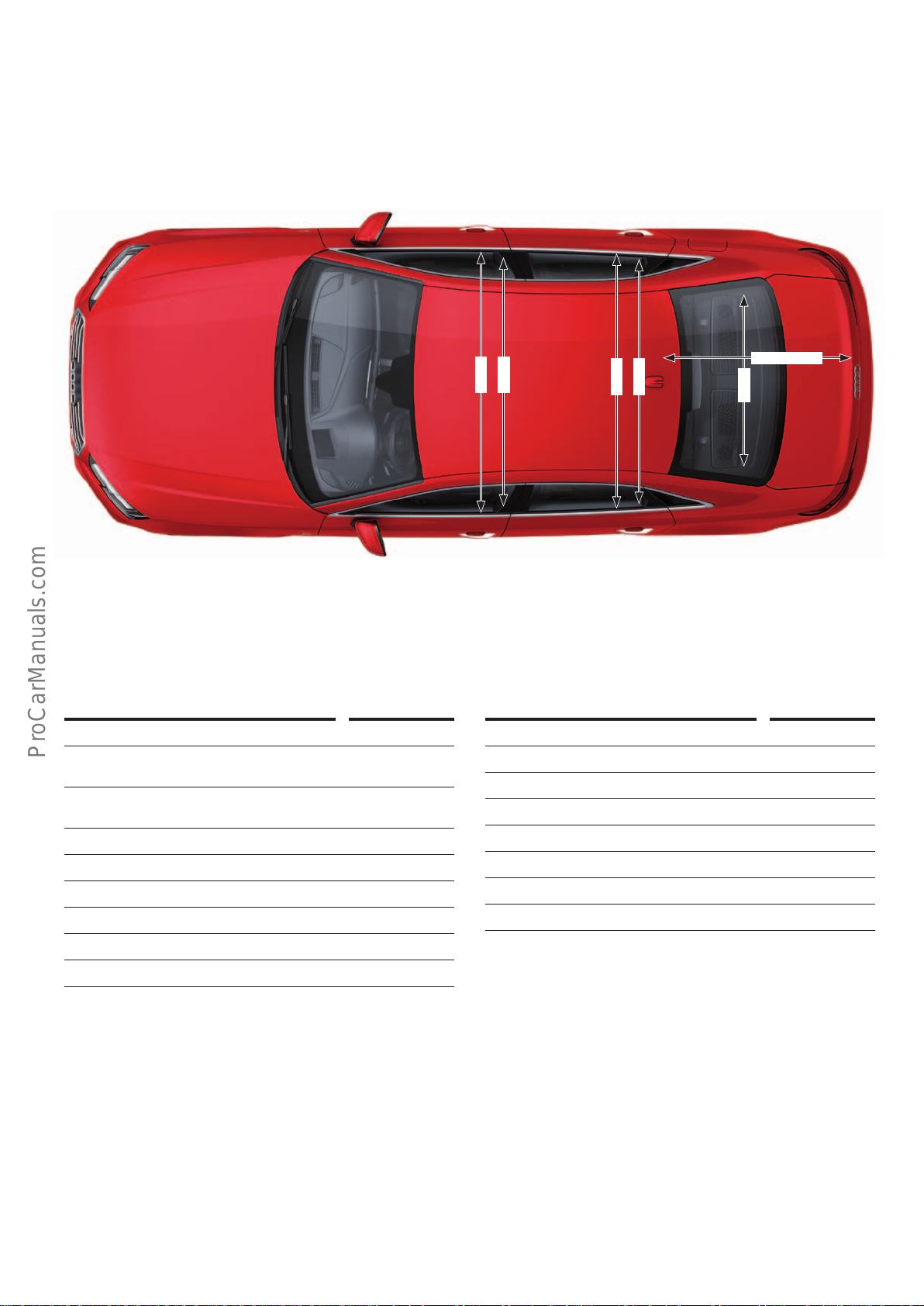
1476
3)
1421
2)
1446
3)
1384
1081/1050
1000
4)
644_050
Exterior dimensions and weights
Length in mm 4726
Width (not including exterior
mirrors) in mm
Width (including exterior mirrors)
in mm
Height in mm 1427/1434
Front track width in mm 1572
Rear track width in mm 1555
Wheelbase in mm 2820
Kerb weight in kg 1430
Gross vehicle weight in kg 2030
1)
Maximum headroom
2)
Elbow room width
3)
Shoulder room width
4)
Dimension for AudiA4Avant
5)
Front wheel drive / front wheel drive (optional) / quattrodrive
1842
2022
Inner dimensions and other specifications
Front cabin width in mm 1476
Front shoulder width in mm 1421
Rear cabin width in mm 1466
Rear shoulder width in mm 1384
4)
Load sill height in mm 684/634
Boot capacity in l 480/505
Drag coecient c
w
Capacity of fuel tank in l 40/54/58
2)
3)
2)
3)
0.23/0.26
4)
4)
4)
5)
All dimensions are given in millimetres and refer to the unladen weight of the vehicle.
7
Page 8
Body
< Back
Forward >
Ξ Contents
Introduction
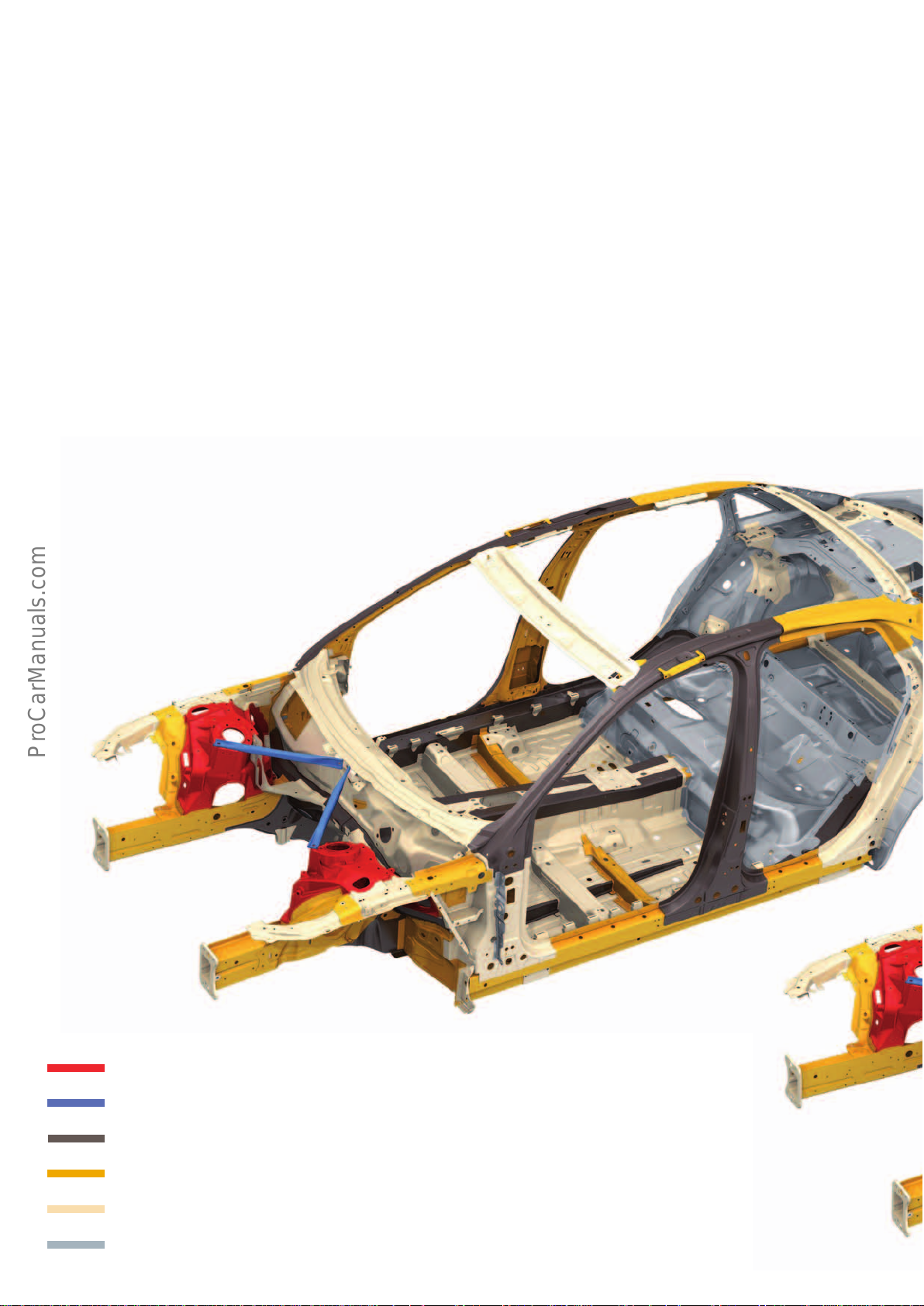
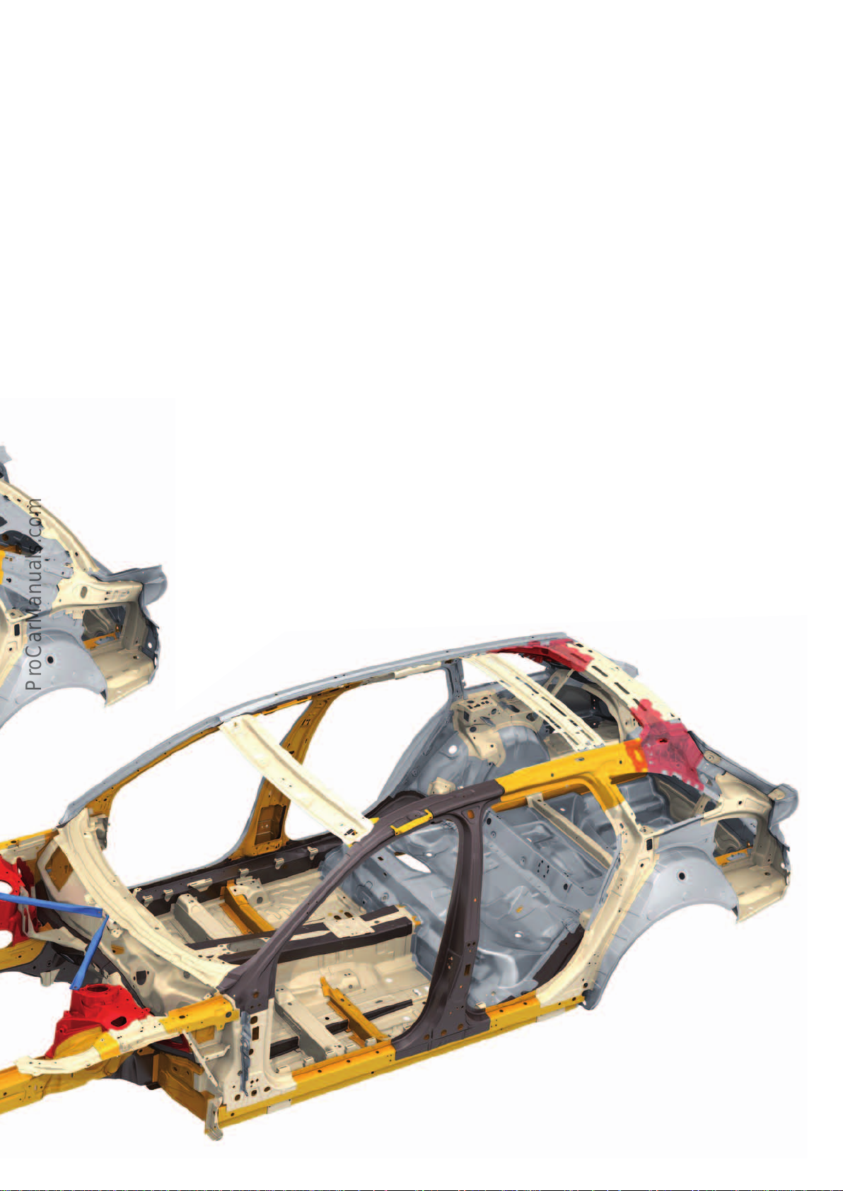
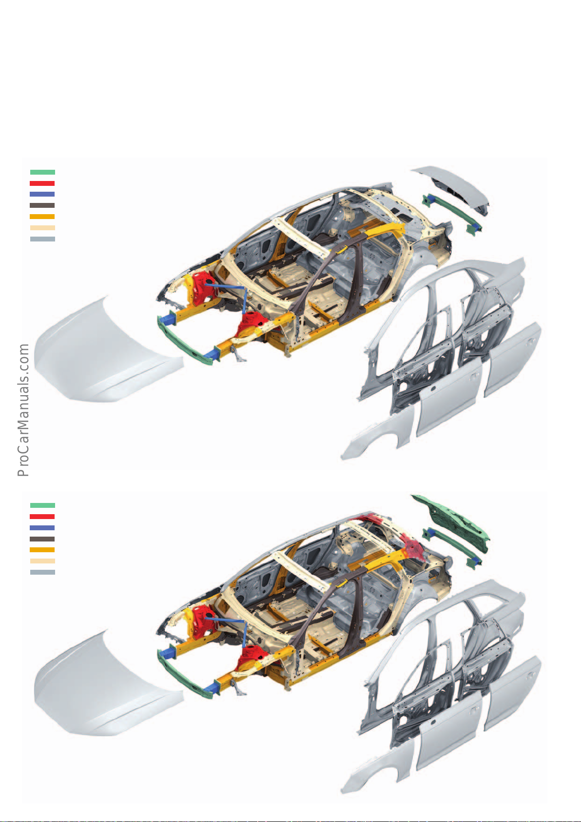
The Audi A4 saloon and the Audi A4 Avant bodies have a hybrid
design. This lightweight construction concept utilises die-cast
aluminium components in addition to regular sheet-metal parts.
Adecisive factor in modern body construction is the lightness and
rigidty of the body structure as a whole. For this reason, the bodies
of the AudiA4 incorporate die-cast aluminium components in addition to soft, high-strength, modern high-strength and ultra-highstrength sheet-steel components (2 in the saloon and 4 in the
Avant).
Body structure
Ultra-high-strength hot-stamped components are used in the
following areas:
• Front frame side member
• Front side member reinforcement
• Bulkhead (tunnel bridge)
• A post
• B post
• Inner chassis rail (sill)
• Upper tunnel reinforcement
• Rear frame side member
These are the front spring strut mounts and the nodes at the upper
end of the D posts on the Audi Avant A4.
Thanks to geometrical lightweight construction and an intelligent
material mix, the body of the Audi A4 is 15 kg lighter than that of
the Audi A4 (type 8K).
Key:
Die-cast aluminium
Aluminium profile
Ultra-high-strength steel (hot-stamped)
Advanced high-strength steel
High-strength steel
Soft steel
8
Page 9
Ultra-high-strength steel (hot-stamped)
< Back
Forward >
Ξ Contents
In the Audi A4 saloon and in the Audi A4 Avant, hot-stamped
components form the high-strength, crash-proof backbone of the
occupant cell. They strengthen the transition from the front end to
the cabin, the frontal area of the roof frame (A post), the B posts,
the lower beams and parts of the floorpan. They constitute 17 %
of the body structure.
Sectional repairs may be performed on the following heat-stamped
components:
• A post
• B post
Special care must be taken when handling hot-stamped steel
during servicing. This material must not be straightened or
reshaped, even if the deformation is only minimal, due to its high
yield strength and rebound eect.
For this reason, attention was given to special service solutions
during the development of the body structure. This means that
damaged components are replaced fully or partially in specially
designated parting cut areas (depending on energy flow).
All other hot-stamped components must, if damaged, be completely replaced to manufacturer specifications. This is because
high heat input into the welding area would irreversibly compromise the strength and structure of the component by causing
microstructural changes in the material.
644_152
644_153
9
Page 10
Outer skin
< Back
Forward >
Ξ Contents
Both Audi A4 models have a steel outer skin. The attachments are
also made of steel. Only the impact absorbers and the rear hatch
of the Audi A4 are made of aluminium. The hatch is deep-drawn in
the press using what is known as an "intelligent" tool.
Outer skin of the A4 saloon
Sheet aluminium
Die-cast aluminium
Aluminium profile
Ultra-high-strength steel (hot-stamped)
Advanced high-strength steel
High-strength steel
Soft steel
Laser sensors measure how the sheet metal behaves during the
shaping process. If necessary, electrically operated drawing aids
make small adjustments to the press. This results in even higher
precision in the magnitude of thousandths of a millimetre.
Outer skin of the Audi A4 Avant
Sheet aluminium
Die-cast aluminium
Aluminium profile
Ultra-high-strength steel (hot-stamped)
Advanced high-strength steel
High-strength steel
Soft steel
644_154
644_155
10
Page 11
Aluminium castings
< Back
Forward >
Ξ Contents
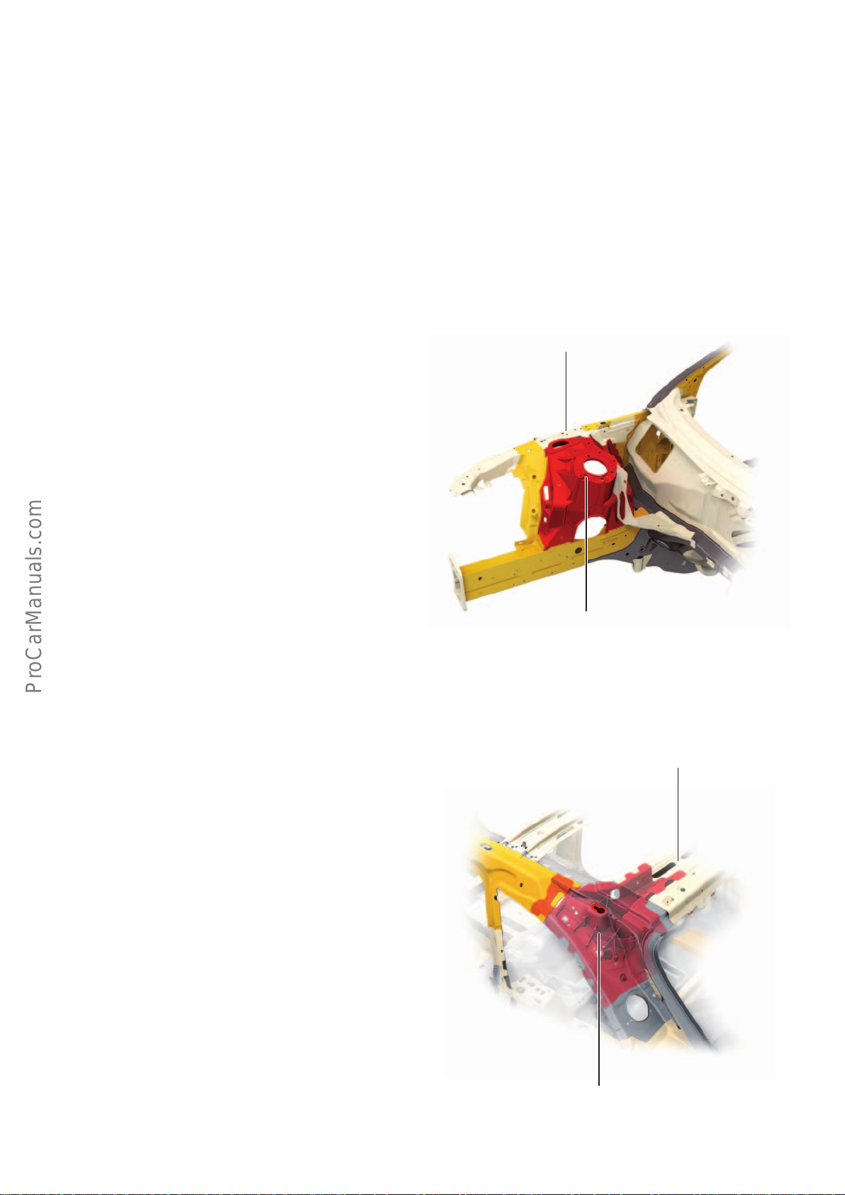
The aluminium castings in the vehicle structure are joined to the
adjacent sheet-metal parts by punch riveting and using structural
adhesive. The adhesive also serves to insulate both materials from
one another, thus preventing contact corrosion.
Specific repair solutions have been developed for repairing damage
to these aluminium castings and adjoining sheet-steel parts.
Straightening and reshaping work is not permitted in the area of
these components.
Structural integration of the spring strut mounts in the AudiA4saloon and AudiA4Avant
The front spring strut mounts are highly integrated die-cast
aluminium components. Compared with sheet-steel components,
which are welded together out of several parts, they reduce weight
in the AudiA4 by a total of 8 kg. This design allows a very sti
connection between the upper wishbones and the car body, thus
ensuring optimal conditions for driving dynamics.
Side member, wheel arch upper end
(wing stay)
Structural integration of the upper D post node on the AudiA4Avant
There are two die-cast aluminium nodes in the upper D posts on
the AudiA4Avant. The component incorporates the hinge mounts
for the rear hatch attachment and the roof rail mount.
644_156
Spring strut mount
Rear roof frame
644_157
Node, D post upper end
11
Page 12
Attachments
< Back
Forward >
Ξ Contents
Striker on the boot
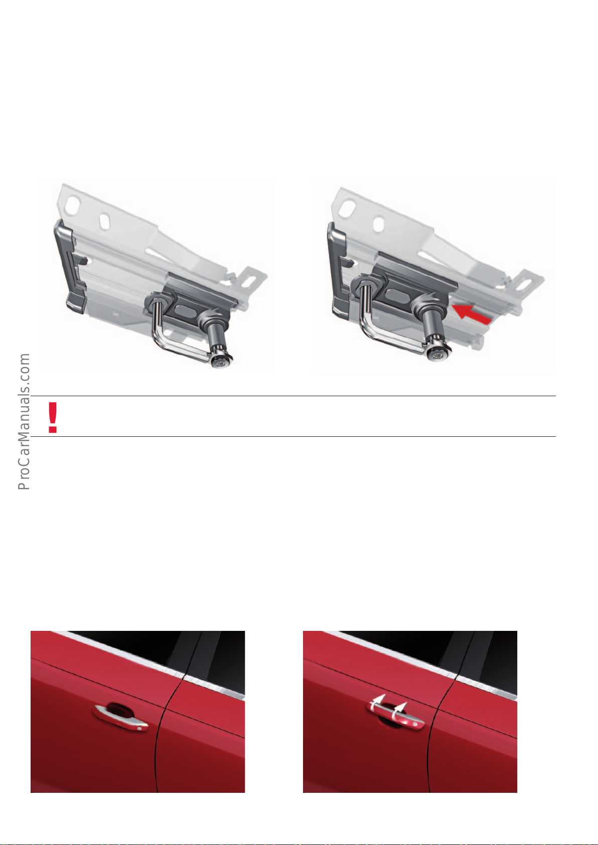
If the AudiA4 (type8W) is equipped with an active pedestrian
protection system, the bonnet is displaced upwards and backwards
when a collision with a pedestrian is detected. To facilitate this
type of displacement, long strikers which allow longitudinal
Initial position Position when bonnet is deployed
movement within the catch hooks are fitted in the other Audi
models. In certain markets, "movable" strikers are used on the
AudiA4 (type8W). The maximum displacement is approximately
50 mm.
644_109
Note
Refer to the current service literature for information on replacement of the strikers after deployment of the pedestrian
protection system.
Door handles
The kinematics of the door handles on the AudiA4 (type8W) have
been modified. Whereas door handles typically move in a horizontal direction only, this door handle now also swivels approximately
30° upwards.
644_110
This results in an intuitive action which is anatomically adapted to
the movement of the hand and provides better ergonomics when
opening the door.
12
644_106
644_107
Page 13
Active radiator louvre
< Back
Forward >
Ξ Contents
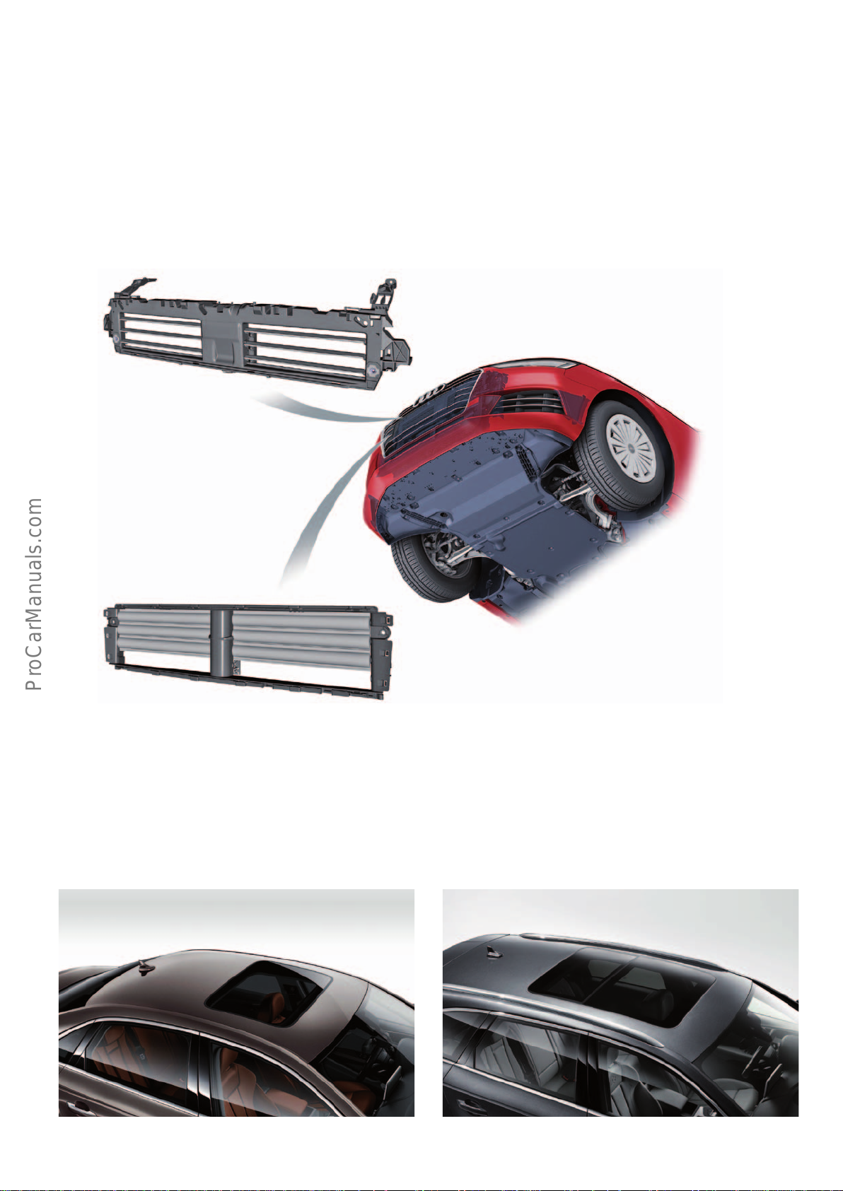
Depending on engine type, the AudiA4 (type8W) may be equipped
with an active cooling air intake system which improves aerodynamics and assists the thermal management system.
Unlike the AudiQ7(type 4M), the A4 features a split active cooling
air intake system. The upper and lower louvres can be activated
separately.
Upper radiator louvre
Three positions are possible depending on various input variables
such as coolant temperature, engine temperature, gearbox temperature and exhaust gas temperature.
• Both units closed
• The lower unit open and the upper unit closed (to ensure earlier
air flow through the charge air cooler).
• Both units open
The lower louvre does not have a bottom plate. This ensures a
continuous, forced flow of air through the charge air cooler. Both
units are open upwards of a speed of 160 kph.
Lower radiator louvre
Roof variants
Sliding sunroofs are optional for the A4saloon and the A4Avant.
The sunroof option for the saloon is a regular sliding sunroof with
a moving glass panel.
644_111
The A4Avant has a two-section panoramic glass sunroof where the
rear panel is fixed and the front panel is movable.
AvantSaloon
644_104 644_105
13
Page 14
Seating systems
< Back
Forward >
Ξ Contents
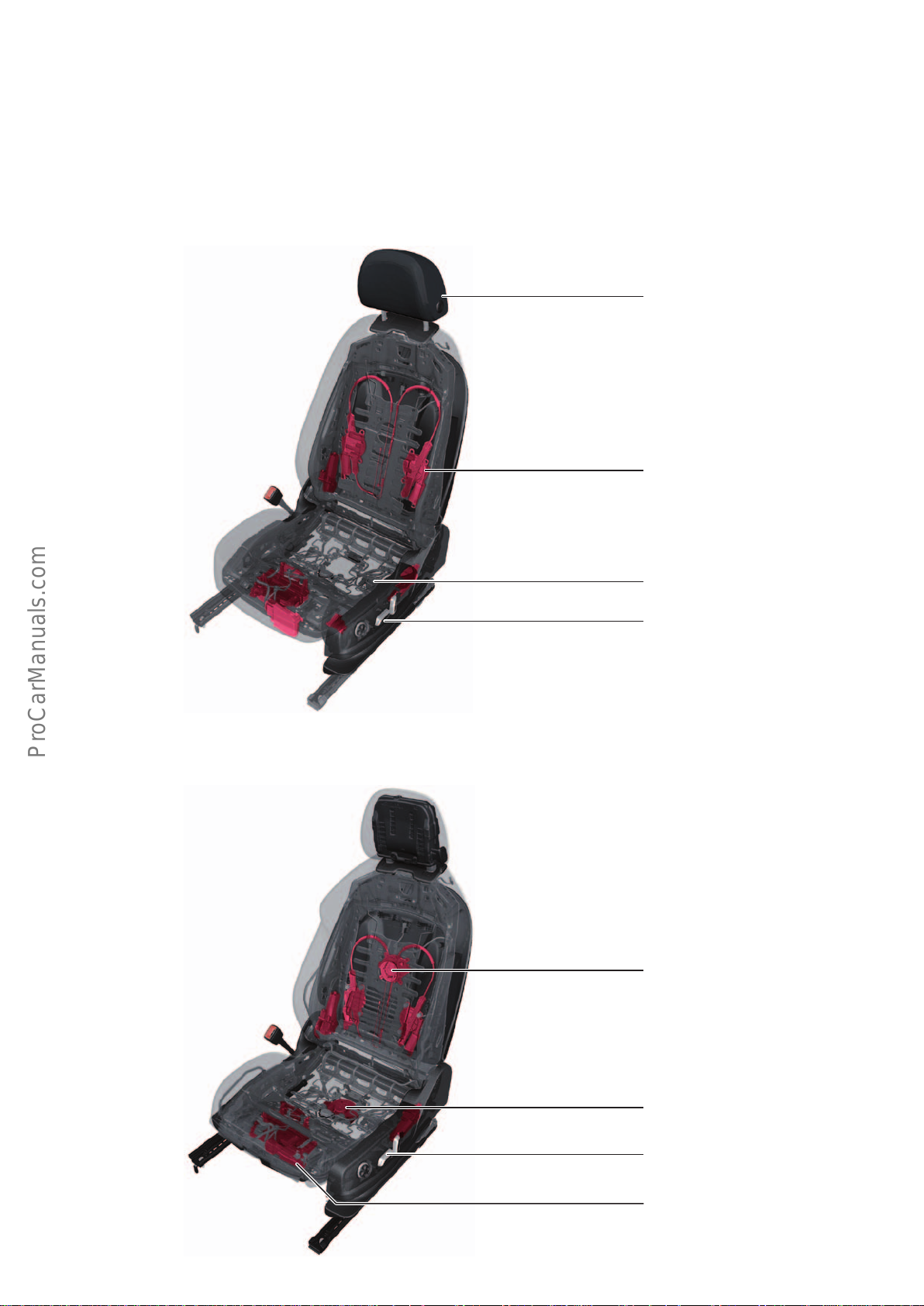
The Audi A4 and A4Avant have front seats tailored to the contours
of the body. The head restraints are adjustable for height and
distance to the back of the head.
The standard seats are optionally available with heating and partial
or full electrical adjustment.
Standard front seat
A central armrest in the front – adjustable if desired and with a
large storage space – large door pockets and two cup holders are
standard features, providing enhanced seating comfort.
Head restraints with manual adjustment
for height, angle and distance
Optional electrical lumbar support
Sport seat
The optional sport seats have electrically
adjustable lumbar supports and are
optionally available with seat ventilation.
Front seat subframe
of high-strength steel
Optional electric seat adjustment
644_009
Seat vent
V388/V389
Seat vent
V390/V391
Operating unit for driver seat adjustment
E470
Seat control units
J136/J521
644_010
14
Page 15
Seat memory
< Back
Forward >
Ξ Contents
The memory function allows personal seating profiles to be stored
for the driver and recalled. The memory function can be operated
with the remote control key and with the recall buttons in the
driver's door.
Whenever the vehicle is locked, the driver's seat profile is re-stored
and assigned to the remote control key. The seat profile is automatically recalled when the door is opened.
The settings for the seats and the two door mirrors can be stored
as indicated in the adjacent table.
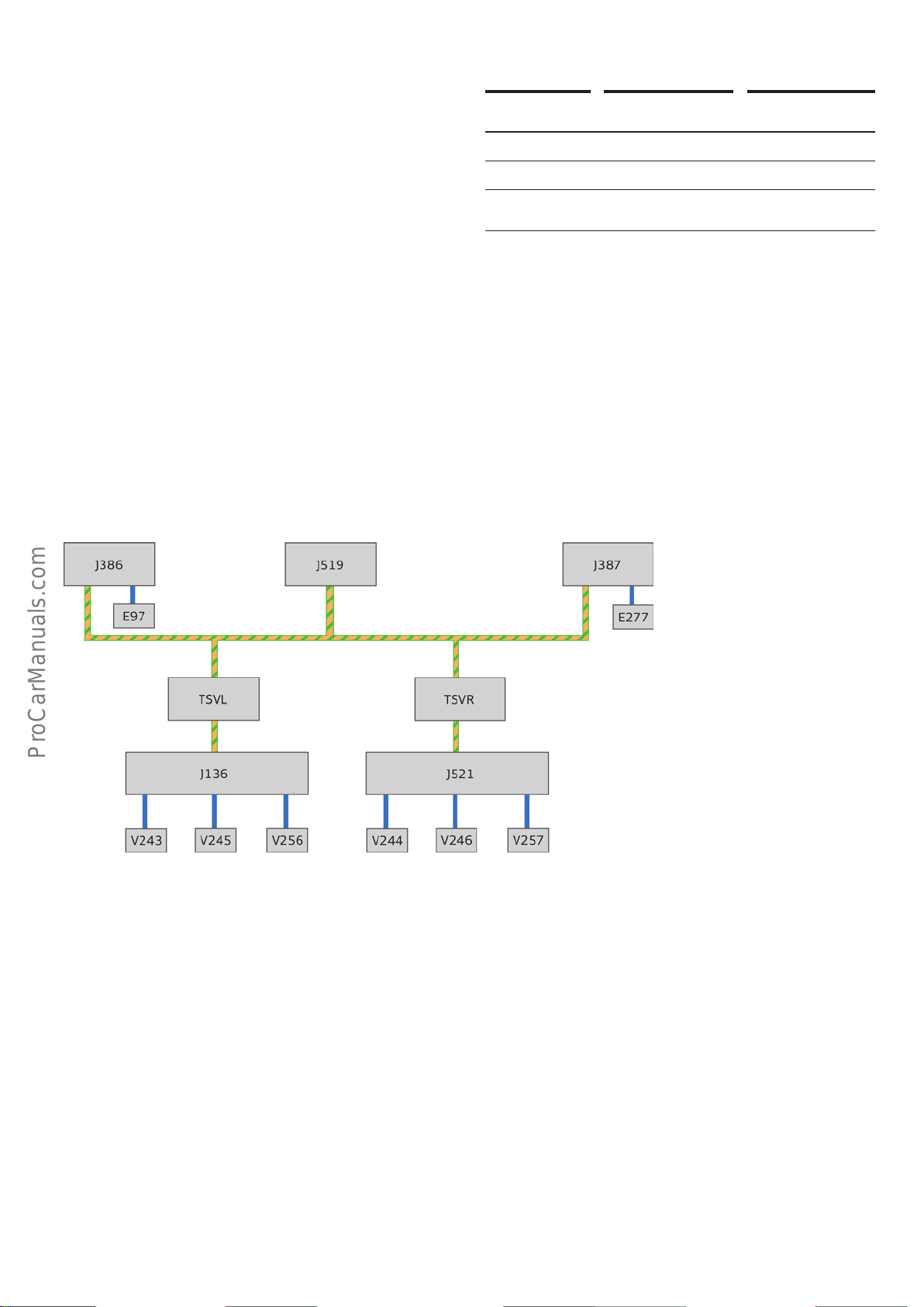
System overview and signal characteristic
The information from the operating units for the driver/front
passenger seat with memory function E97/E277 is processed by
the two driver/front passenger door control units J386/J387.
Remote
control key
Driver Driver
Seat x x
Both
door mirrors
This information is transferred to the two seat control units with
memory function J136/J521 via the convenience CAN. The seat
control units then activate the corresponding control motors.
x x
Recall button
Key:
E97 Operating unit for driver seat adjustment with memory
function
E277 Operating unit for front passenger seat adjustment with
memory function
J136 Seat and steering column adjustment
control unit with memory function
J386 Driver's side door control unit
J387 Door control unit, pass. side
J519 Electrical system control unit
J521 Front passenger seat adjustment control
unit with memory
Convenience CAN
644_027
V243 Driver seat angle adjustment motor
V244 Front passenger seat angle adjustment motor
V245 Driver seat height adjustment motor
V246 Front passenger seat height adjustment motor
V256 Driver seat depth adjustment motor
V257 Front passenger seat depth adjustment motor
TSVL Front left seat coupling
TSVR Front right seat coupling
15
Page 16
Occupant protection
< Back
Forward >
Ξ Contents
Passive safety
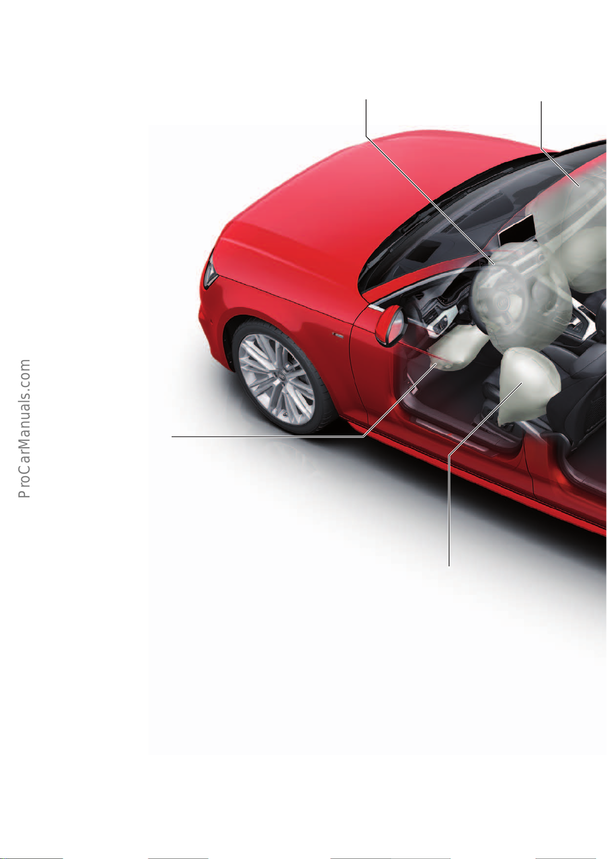
On the following pages you will find a summary of the occupant
protection system in the Audi A4.
In-car airbags
Front pass. airbagDriver airbag
Driver side knee airbag
Components
Depending on country version and trim level, the passive occupant
and pedestrian protection system in the Audi A4 can comprise the
following components and systems:
• Airbag control unit
• Adaptive driver airbag
• Adaptive front passenger airbag
(front passenger airbag, two-stage country version)
• Front side airbags
• Rear side airbags (equipment option)
• Head airbags
• Knee airbags (country version)
• Front airbag crash sensors
• Crash sensors for side impact detection in the doors
• Crash sensors for side impact detection in the C posts
• Centre pedestrian protection crash sensor
(acceleration sensor, country version)
• Left and right pedestrian protection crash sensors
(pressure sensors, country version)
Front side airbag
• Front inertia-reel seat belts with pyrotechnic belt tensioners
• Front inertia-reel seat belts with electrical belt tensioners
• Front inertia-reel seat belts with active belt force limiters
• Inertia-reel seat belts for second seat row with pyrotechnic belt
tensioners, driver and front passenger sides
(country or trim level version)
• Seat belt warning for all seats (country version)
• Seat occupancy sensor in front passenger seat
• Front pass. airbag disabling switch (country version or trim level
version)
• Front pass. airbag OFF and ON warning lamp
(country version or trim level version)
• Driver and front passenger seat position sensors
• Pedestrian protection trigger (country version)
• Battery isolator
16
Page 17
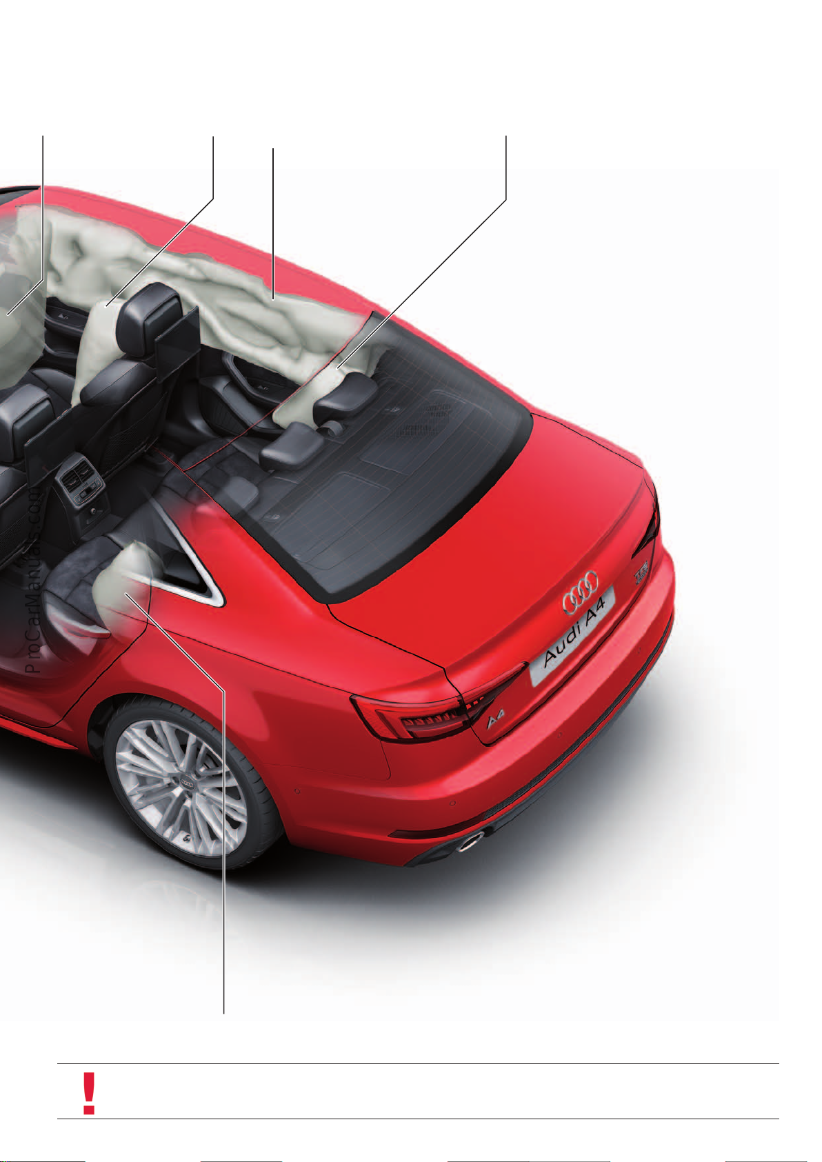
Pass. side knee airbag
< Back
Forward >
Ξ Contents
Front side airbag Head airbag,
driver and front pass. side
Rear side airbag
Rear side airbag
644_115
Note
The schematic diagrams in the chapter "Occupant protection" provide a better understanding.
17
Page 18
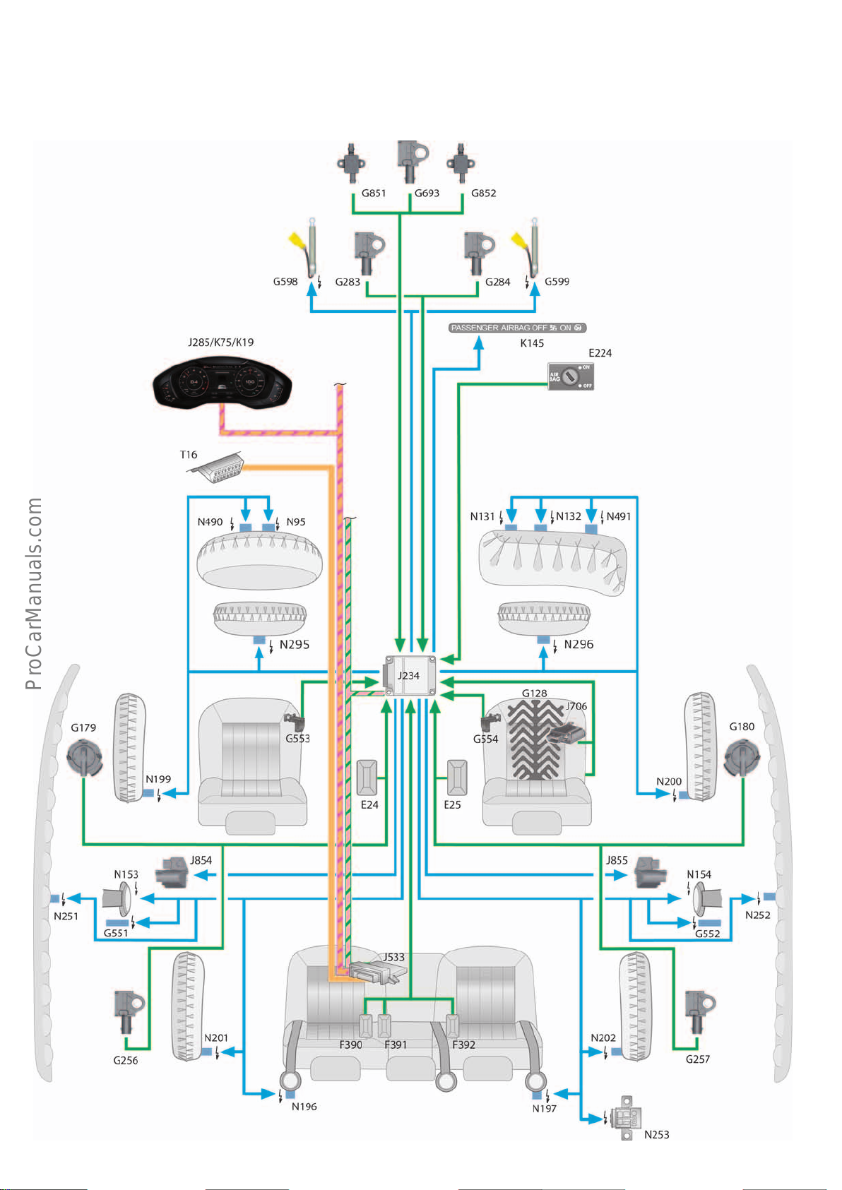
System overview
< Back
Forward >
Ξ Contents
The system overview shows the components for all markets. Keep in
mind that this constellation is not possible in a production model.
644_003
18
Page 19

Additional equipment
< Back
Forward >
Ξ Contents
Equipment specifications may vary due to the dierent requirements and statutory provisions which apply to vehicle manufacturers in the various markets.
Key to figure on page 18:
E24 Driver side seat belt switch
E25 Front pass. side seat belt switch
E224 Airbag disabling switch, pass. side
F390 Driver side seat belt switch, 2nd seat row
F391 Centre belt switch, 2nd seat row
F392 Front pass. side seat belt switch, 2nd seat row
G128 Pass. side seat occupancy sensor
G179 Side airbag crash sensor, driver side
G180 Side airbag crash sensor, pass. side
G256 Rear side airbag crash sensor, driver side
G257 Rear side airbag crash sensor, pass. side
G283 Front airbag crash sensor, driver side
G284 Front airbag crash sensor, pass. side
G551 Belt force limiter, driver side
G552 Belt force limiter, pass. side
G553 Seat position sensor, driver side
G554 Seat position sensor, pass. side
G598 Pedestrian protection actuator 1
G599 Pedestrian protection actuator 2
G693 Centre pedestrian protection crash sensor
G851 Driver side crash sensor for pedestrian impact mitigation 2
G852 Pass. side crash sensor for pedestrian impact mitigation 2
J234 Airbag control unit
J285 Control unit in dash panel insert
J533 Data bus diagnostic interface (gateway)
J706 Seat occupancy recognition control unit
J854 Front left seat belt tensioner control unit
J855 Front right seat belt tensioner control unit
K19 Seat belt reminder warning lamp
K75 Airbag warning lamp
K145 Front pass. airbag OFF warning lamp (ON and OFF status of
front pass. airbag is indicated)
N95 Driver side airbag igniter
N131 Front pass. side airbag igniter 1
N132 Front pass. side airbag igniter 2
N153 Seat belt tensioner igniter 1, driver side
N154 Seat belt tensioner igniter 1, pass. side
N196 Rear seat belt tensioner igniter, driver side
N197 Rear seat belt tensioner igniter, pass. side
N199 Side airbag igniter, driver side
N200 Side airbag igniter, pass. side
N201 Rear side airbag igniter, driver side
N202 Rear side airbag igniter, pass. side
N251 Head airbag igniter, driver side
N252 Head airbag igniter, pass. side
N253 Battery isolation igniter
N295 Knee airbag igniter, driver side
N296 Knee airbag igniter, pass. side
N490 Driver airbag relief valve igniter
N491 Front pass. airbag relief valve igniter
T16 16-pin connector, diagnostic port
Wire colours:
Diagnostics CAN
Infotainment CAN
FlexRay
Input signal
Output signal
19
Page 20
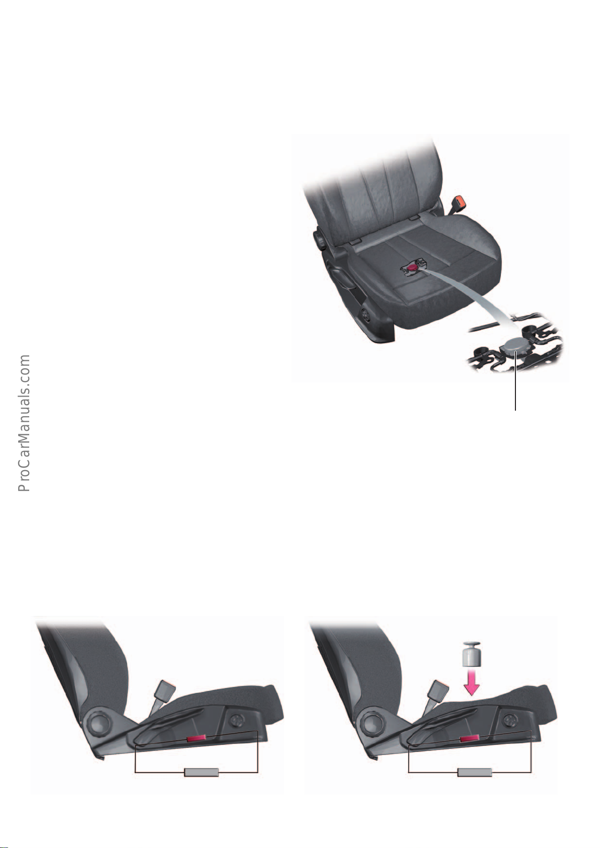
Sensors
< Back
Forward >
Ξ Contents
Seat occupancy sensor
Due to the dierent statutory requirements applicable in the
marketplace, two dierent versions of the seat occupancy sensor
are used in the Audi A4.
Version 1 für ROW1) vehicles
Passenger side seat occupancy sensor G128
The AudiTT(type FV) uses a new-generation passenger side seat
occupancy sensor G128. This new-generation seat occupancy
sensor is also installed on the Audi A4.
The seat occupancy sensor oers the following benefits for
customers and service:
• Low parts diversity
• Easy installation and removal, no need to remove seat
upholstery
• Minimal labour time during replacement
• Minimal repair cost during replacement
• No influence on seat ventilation (optional equipment)
Installation location
The seat occupancy sensor is attached to the seat assembly at the
bottom of the wire frame by clips. The seat upholstery and seat
cover are located overhead. When a person sits on the seat, the
seat upholstery is pushed downwards by weight force thereby
activating the seat occupancy sensor. When the person occupying
the seat stands up, the seat upholstery rebounds upwards,thus
relieving the load on, and thus deactivating, the seat occupancy
sensor.
Function
The seat occupancy sensor is used for the purpose of detecting an
occupant on the front passenger seat. The seat occupancy sensor
has a resistance of approximately 400ohms in the non-activated
state. This value means that no-one is occupying the seat. If a
person is occupying the seat, the seat occupancy sensor is activated and its resistance changes to approximately 100 ohms.
644_004
Pass. side seat
occupancy sensor
G128
The resistance values tell the airbag control unit if the front
passenger seat is occupied or vacant.
If the airbag control unit J234 recognises an occupied seat and the
latch plate of the inertia-reel seatbelt is not engaged in the seat
belt buckle, the airbag control unit J234 activates the audible and
visual seat belt reminders.
1)
ROW = rest of world
20
kg
400Ω 100Ω
644_005
644_006
Page 21
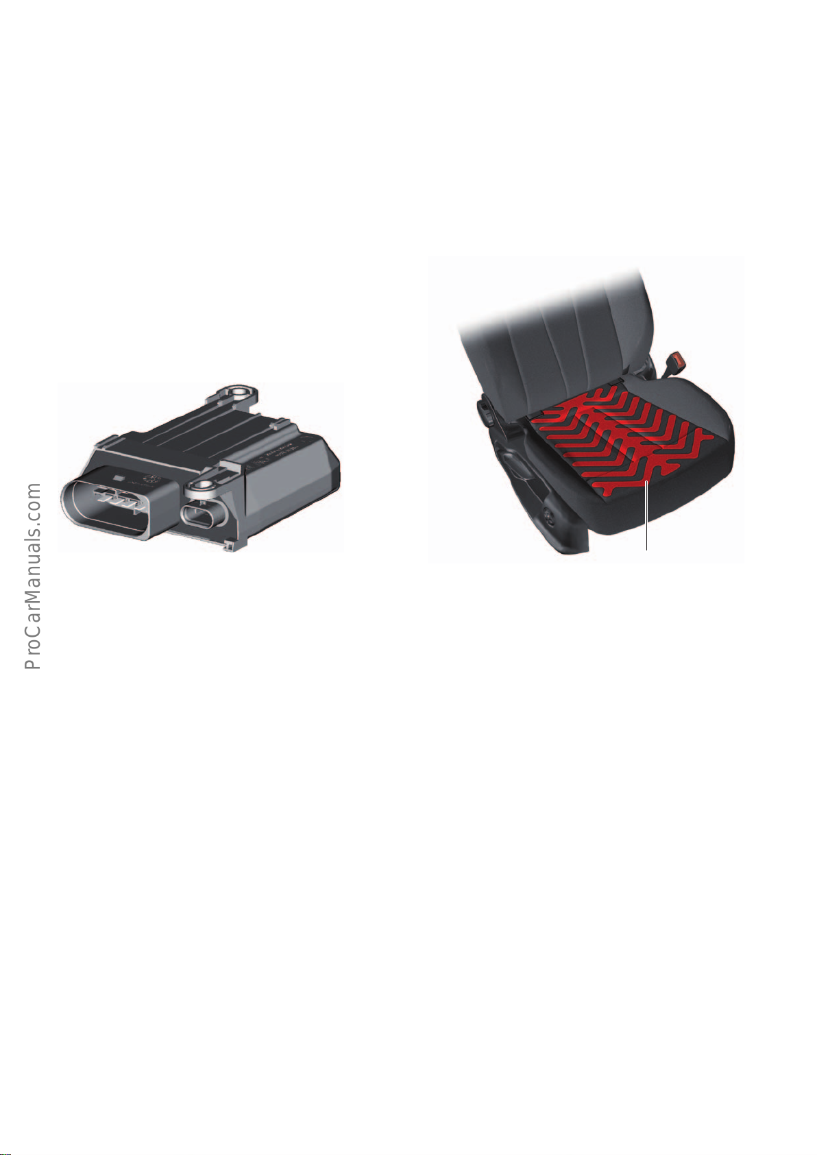
Version 2 für NAR1) vehicles
< Back
Forward >
Ξ Contents
Pass. side seat occupancy sensor G128 with
seat occupancy recognition control unit J706
Until now, the capacitive systems which were first oered in the
AudiA7Sportback (type4G) used a separate sensor mat (pass.
side seat occupancy sensor G128) to determine if a front passenger seat is occupied or vacant.
The AudiTT(type FV) uses a new-generation passenger side seat
occupancy sensor G128 in NAR1) models. In this new-generation
system, the seat heater element (front passenger seat heater Z8)
serves not only as a seat heater but also as a sensor mat for seat
occupancy recognition. As before, capacitive sensors are used for
occupancy recognition.
For the sake of simplicity, the following text refers solely to the
passenger side seat occupancy sensor G128, although the sensor
mat also serves as the front passenger seat heater Z8 as described
above.
The seat occupancy recognition control unit J706 is connected to
ground (the seat assembly) by a discrete wire.
To prevent interference with the capacitive system, the wires
leading to the passenger side seat occupancy sensor G128 are
shielded.
The seat occupancy recognition control unit J706 is connected to
the airbag control unit J234 by means of a LIN bus.
Service Kit
In the Service Kit, the seat occupancy recognition control unit J706
and the passenger side seat occupancy sensor G128 are calibrated
to one another. This is why a new Service Kit must be installed in
the event of a fault in the control unit or in the seat occupancy
sensor. It is not permitted to interchange individual components.
Service Kit version 1
• Seat occupancy recognition control unit J706
• Seat cushion
• Passenger side seat occupancy sensor G128 including wiring
kit. In this case, the passenger side seat occupancy sensor is
bonded to the seat upholstery.
Vehicles without seat heating use the same passenger side seat
occupancy sensor G128 as vehicles with seat heating.
644_012
Pass. side seat
occupancy sensor
G128
The electrical plug connection between the seat occupancy recognition control unit J706 and the passenger side seat occupancy
sensor must not be disconnected. Depending on vehicle trim level,
the Service Kit may comprise the following components:
Service Kit version 2
• Seat occupancy recognition control unit J706
• Seat upholstery
• Passenger side seat occupancy sensor G128 including wiring
kit. In this case, the passenger side seat occupancy sensor is
stitched to the seat upholstery.
644_013
Diagnostics
The passenger side seat occupancy sensor G128 and the seat
occupancy recognition control unit J706 are diagnosed via the
airbag control unit J234.
1)
NAR = North American Region
If a Service Kit is replaced, a basic setting procedure must be
performed using the Guided Fault Finding function. In this case,
the serial number of the Service Kit is transferred to the airbag
control unit J234.
21
Page 22
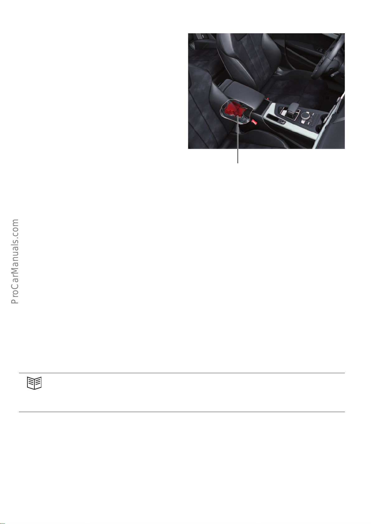
Airbag control unit J234
< Back
Forward >
Ξ Contents
The airbagcontrol unit J234 of the AudiA4 is based on the same
control unit generation used in the AudiQ7 (type4M). The system
designation of the airbagcontrol unit is "Airbag10.44" and can be
recalled in the Guided Fault Finding under "Control unit identification".
The features and the setup of the airbagcontrol unit J234 have
been adapted to suit the AudiA4. For details of the equipment
specification, refer to the system overview on page 18.
644_103
Airbag control unit
J234
Sensors
As previously in the Audi Q7 (type4M), the driving dynamics
control sensors are integrated in the airbag control unit in the
AudiA4. The driving dynamics control sensors measure acceleration in the X and Y directions as well as the yaw rate about the Z
axis.
The driving dynamics control sensors work in a lower acceleration
and deceleration range than the crash sensors. This acceleration
and deceleration levels which can occur during a collision are
clearly dierent to those which can occur when a vehicle loses grip
(e.g. oversteer, understeer).
Reference
More detailed information about the subsystems mentioned herein can be found in the following self study programmes:
• The dynamic steering system: Self Study Programme 402 "Dynamic steering in the AudiA4’08".
• The quattro sport dierential: Self Study Programme 476 "Rear final drive 0BF/0BE - sport dierential".
• The airbag control unit: Self Study Programme 637 "Audi Q7 (type 4M) Occupant protection and infotainment".
The crash sensors for the X and Y directions have the ability to
measure acceleration rates of up to approximately +/- 96g, while
the driving dynamics control sensors have the ability to measure
acceleration rates of up to approximately +/- 5g, where 1g is the
force of gravity or approximately 9.81 m/s
have the ability to measure rates of up to approximately +/- 187°/s
(degrees per second).
If the vehicle is equipped with dynamic steering (PR No.1N8) or
the quattro sport dierential (PR No.GH2), the driving dynamics
control sensors are duplicated in the airbag control unit J234. This
provides redundant (multiple) backup for the sensor signals for
dynamic steering and quattro Sport.
2
. The yaw rate sensors
22
Page 23
Active safety
< Back
Forward >
Ξ Contents
Audi pre sense
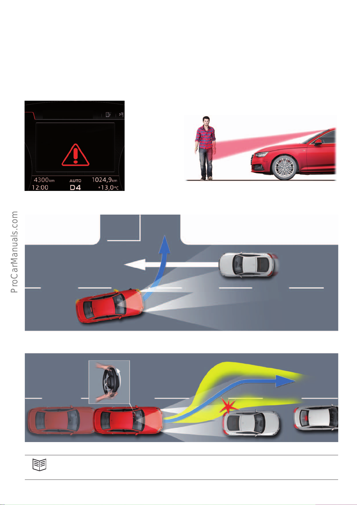
The Audi pre sense system (pre sense city, pre sense basic, pre
sense rear, pre sense front, evasion assist or turn assist) of the
Audi A4 has the same on-board pre sense functions as the AudiQ7
(type4M).
Display in instrument cluster Pre sense city with pedestrian recognition function
Of course, the components and the specifications have been
adapted to suit the A4(type8W). In functional terms, the Audi pre
sense functions in the A4 are identical to those in the AudiQ7.
Audi pre sense
644_030
Turning assist
644_031
Evasion assist
Reference
For detailed information about Audi pre sense, refer to Self Study Programme 637 "AudiQ7(type4M) Occupant Protection
and Infotainment".
644_032
644_033
23
Page 24
Engines
< Back
Forward >
Ξ Contents
Petrol engines
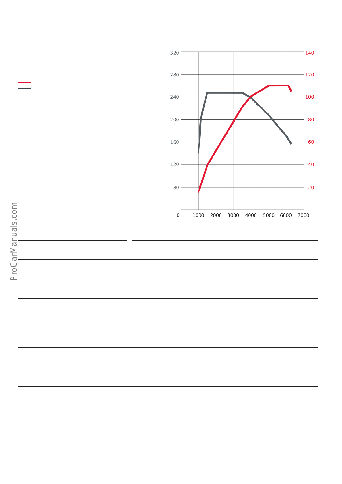
Torque/power curve of 1.4l TFSI engine
Engine with code CVNA
Power output in kW
Torque in Nm
Engine speed [rpm]
Features Specications
Engine code CVNA
Type 4-cylinder inline engine
Displacement in cm
3
1395
Stroke in mm 80.0
Bore in mm 74.5
Number of valves per cylinder 4
Firing order 1-3-4-2
Compression ratio 10,5:1
Power output in kW at rpm 110 at 1500-3500
Torque in Nm at rpm 250 at 5000-6000
Fuel type Premium unleaded 95 RON
Engine management system Bosch MED 17.01.61
Lambda/knock control Adaptive lambda control, adaptive knock control
Mixture formation Sequential direct injection
644_015
Exhaust gas treatment Oxidising catalyst, oxygen sensors (2bistable sensors)
Emission standard EU6 (W)
emissions in g/km 114
CO
2
1)
AudiA4saloon with front wheel drive and Stronic
24
1)
Page 25
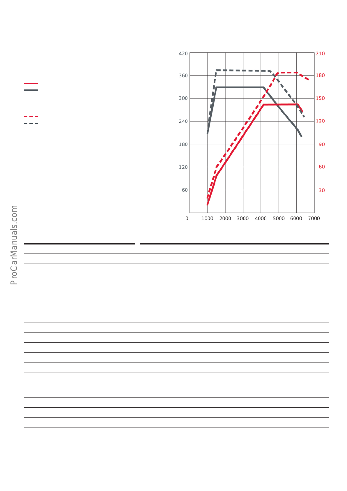
Torque/power curve of 2.0l TFSI engine
< Back
Forward >
Ξ Contents
Engine with code CVKB
Power output in kW
Torque in Nm
Engine with code CYRB
Power output in kW
Torque in Nm
Engine speed [rpm]
Features Specications
Engine code CVKB CYRB
Type 4-cylinder inline engine 4-cylinder inline engine
Displacement in cm
3
1984 1984
Stroke in mm 92.8 92.8
Bore in mm 82.5 82.5
Number of valves per cylinder 4 4
Firing order 1-3-4-2 1-3-4-2
Compression ratio 11.65:1 9.6:1
Power output in kW at rpm 140 at 4200-6000 185 at 5000-6000
Torque in Nm at rpm 320 at 1400-3700 370 at 1600-4500
Fuel type Premium unleaded 95 RON Premium unleaded 95 RON
Engine management system Bosch MED 17.01.10 SIMOS 18.4
Lambda/knock control Adaptive lambda control, adaptive knock control
Mixture formation Combined (dual) direct (FSI) and multipoint (MPI) injection with adaptive idle
charge compensation
Exhaust gas treatment Close-coupled ceramic calatyst, oxygen sensors before and after catalytic converter
644_016
Emission standard EU6 (W) EU6 (W)
CO
emissions in g/km 114
2
1)
AudiA4Avant with front wheel drive and Stronic
2)
AudiA4saloon with front wheel drive and Stronic
3)
AudiA4Avant with quattro drive and Stronic
1)
1292) / 139
3)
25
Page 26
Diesel engines
< Back
Forward >
Ξ Contents
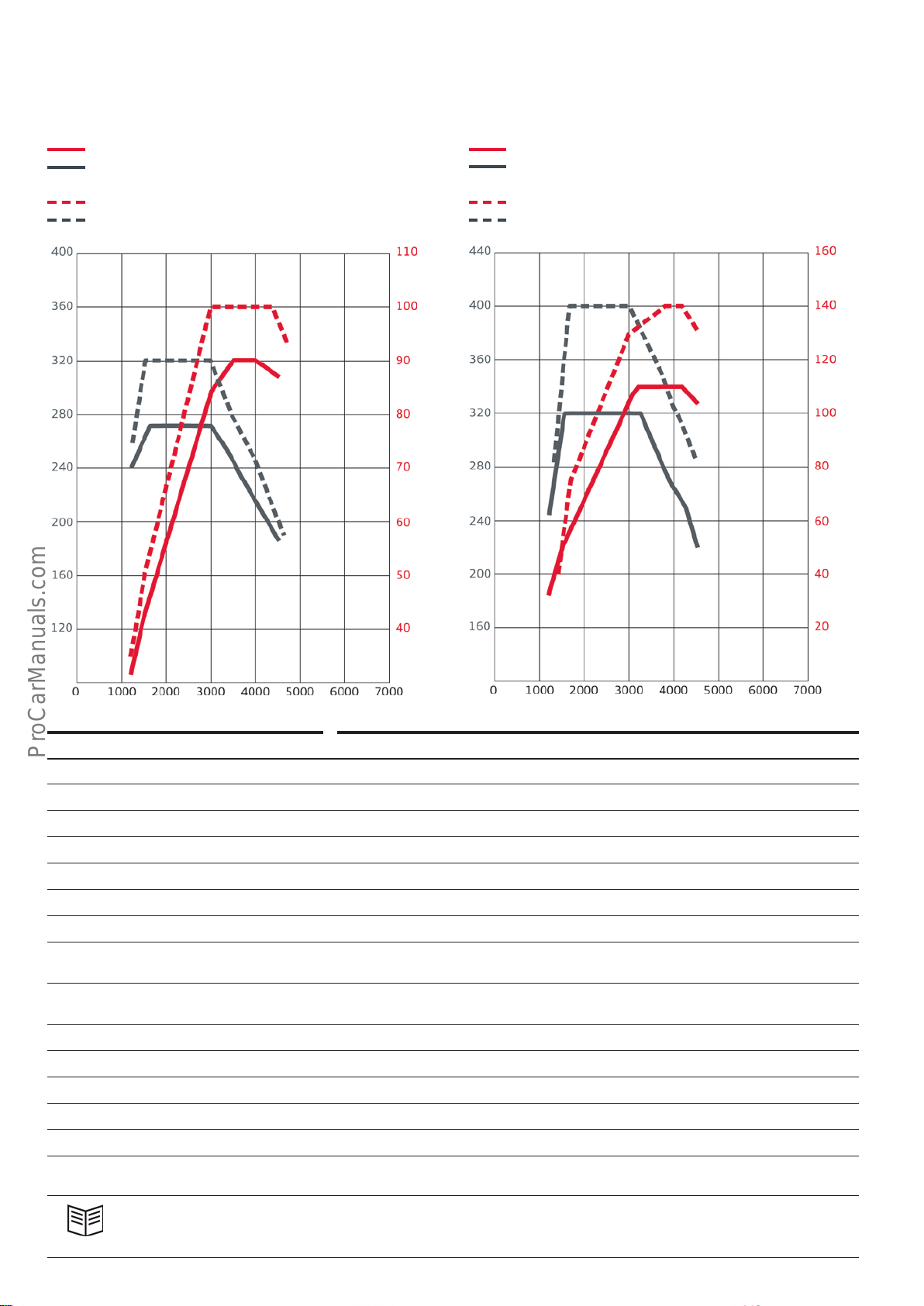
Torque/power curve of 2.0l TDI engine
Engine with code DEUC
Power output in kW
Torque in Nm
Engine with code DEUB
Power output in kW
Torque in Nm
Engine with code DEUA
Power output in kW
Torque in Nm
Engine with code DETA
Power output in kW
Torque in Nm
Engine speed [rpm]
Features Specications
644_017
Engine speed [rpm]
Engine code DEUC DEUB DEUA DETA
Type 4-cylinder inline engine
Displacement in cm
3
1968 1968 1968 1968
Stroke in mm 95.5 95.5 95.5 95.5
Bore in mm 81.0 81.0 81.0 81.0
Number of valves per cylinder 4 4 4 4
Compression ratio 16.2:1 16.2:1 16.2:1 15.5:1
Power output in kW at rpm 90 at
3500–4000
Torque in Nm at rpm 270 at
1500-3000
100 at
3000-4400
320 at
1500-3000
110 at
3250-4200
320 at
1500-3250
140 at
3800-4200
400 at
1750-3000
Engine management system Bosch EDC 17
Maximum injection pressure in bar 2000 with solenoid injectors, 8-hole nozzles
Exhaust gas treatment Oxidising catalyst, SCR coated diesel particulate filter, oxygen sensors
Emission standard EU6 (W) EU6 (W) EU6 (W) EU6 (W)
CO
emissions in g/km –
2
1)
1)
–
992) / 104
3)
1072) / 109
644_018
3)
Reference
For further information about the diesel engines of the Modular Diesel Platform, please refer to Self Study Programme608
"Audi1.6l / 2.0l 4-cylinder TDI engines".
26
Page 27
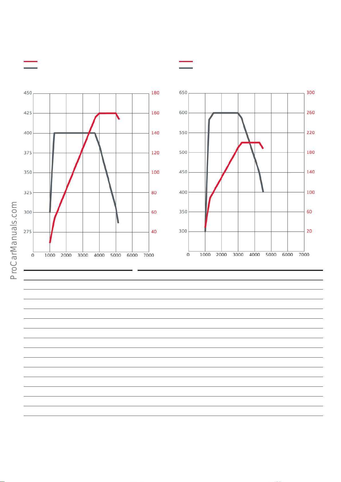
Torque/power curve of 3.0l TDI engine
< Back
Forward >
Ξ Contents
Engine with code CSWB
Power output in kW
Torque in Nm
Engine with code CRTC
Power output in kW
Torque in Nm
Engine speed [rpm]
Features Specications
644_019
Engine speed [rpm]
Engine code CSWB CRTC
Type V6-cylinder engine
Displacement in cm
3
2967 2967
Stroke in mm 91.4 91.4
Bore in mm 83.0 83.0
Number of valves per cylinder 4 4
Compression ratio 16.0:1 16.0:1
Power output in kW at rpm 160 at 4000 – 5000 200 at 3250-4250
Torque in Nm at rpm 400 at 1250-3750 600 at 1500-3000
Engine management system Bosch EDC 17 with start-stop and recuperation
Maximum injection pressure in bar 2000 with piezo injectors
Exhaust gas treatment Close-coupled NO
oxidising catalyst, SCR coated diesel particulate filter
x
Emission standard EU6 (W) EU6 (W)
emissions in g/km 110 1292) / 134
CO
2
644_020
3)
1)
Data was unavailable at time of going to print.
2)
AudiA4saloon
3)
AudiA4Avant
27
Page 28
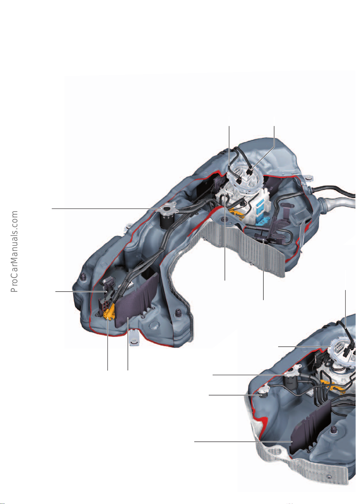
Fuel tank
< Back
Forward >
Ξ Contents
The fuel systems in the AudiA4 (type8W) have the following
features:
• Compact design
• Maximum integration of components to reduce fuel emission
• No carrier plate
• Fuel delivery system with large integral swirl pot
• Use of sound-insulating baes
Diesel-engined models
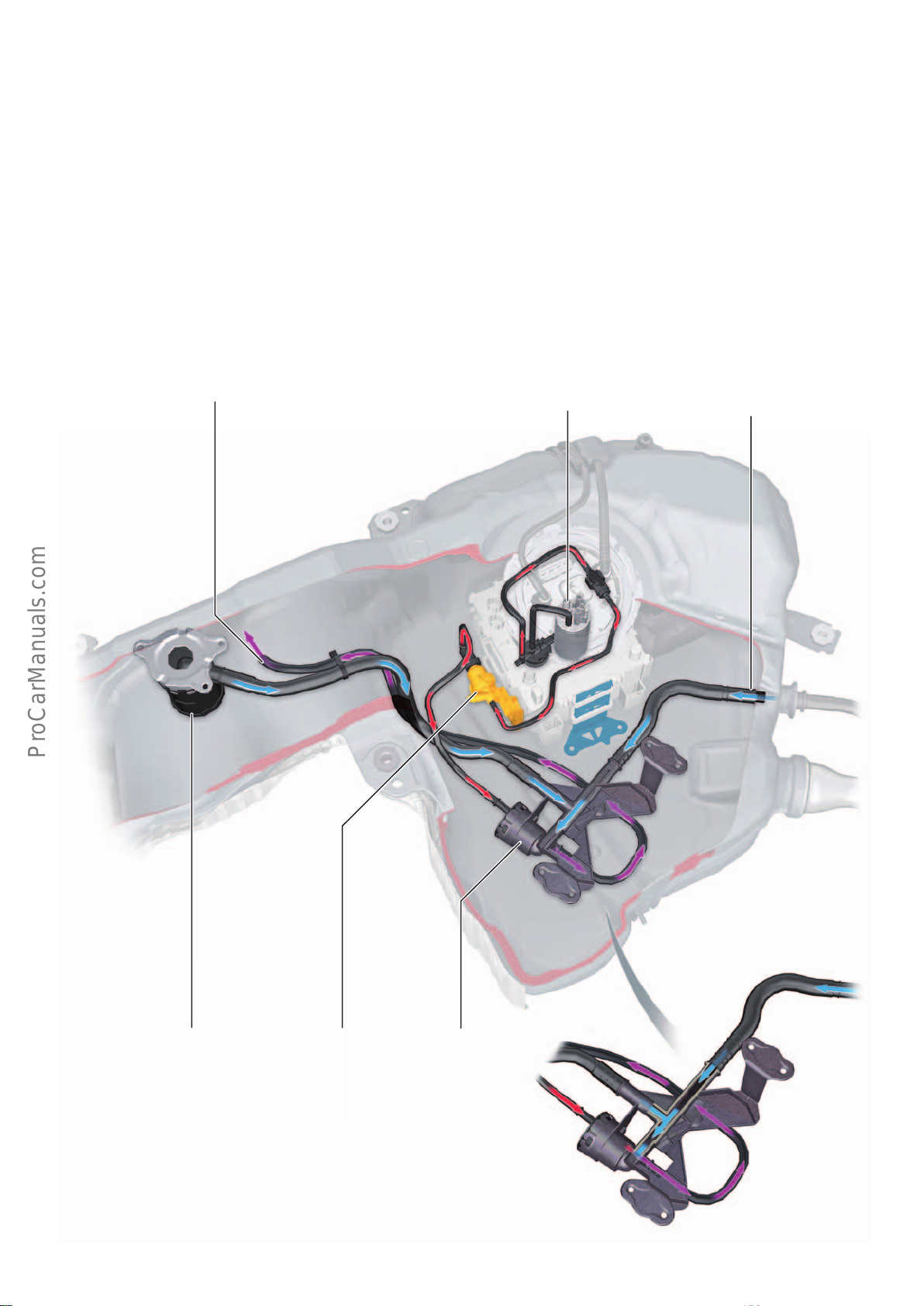
The figure shows the fuel tank of a vehicle with quattro drive
without auxiliary heating.
Fuel vent valve
• The components in the secondary chamber, e.g. fuel level
sender in quattro models, are not accessible to service
personnel. There is only one service port in the fuel tank on
the right.
• A liquid trap with active extraction system is integrated in
the fuel tank ventilation system.
• Fluid separator at top of fuel tank filler neck
Fuel return line
Fuel supply line
Fuel level sender,
left pocket
Suction jet pump
Bae
Fuel vent valve
Rollover valve
Fuel delivery and
sender unit
Suction jet pump of
active extraction system
Fuel delivery and sender unit
644_040
Fuel supply line
Bae
28
Page 29
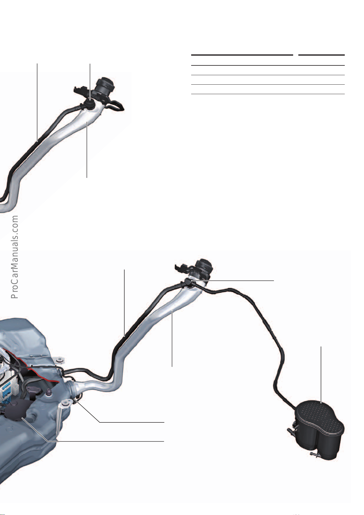
Vent line
< Back
Forward >
Ξ Contents
Rollover valve
Fuel filler neck
Petrol-engined models
Filling volume
Front wheel drive 40 litres
Front wheel drive (optional) 54 litres
quattro drive 58 litres
The figure shows the fuel tank of a vehicle with front wheel drive
and auxiliary heating.
Vent line
Fluid separator
Activated carbon canister
Fuel filler neck
Metering pump (for auxiliary heating)
V54
Liquid trap with active extraction system
644_039
29
Page 30
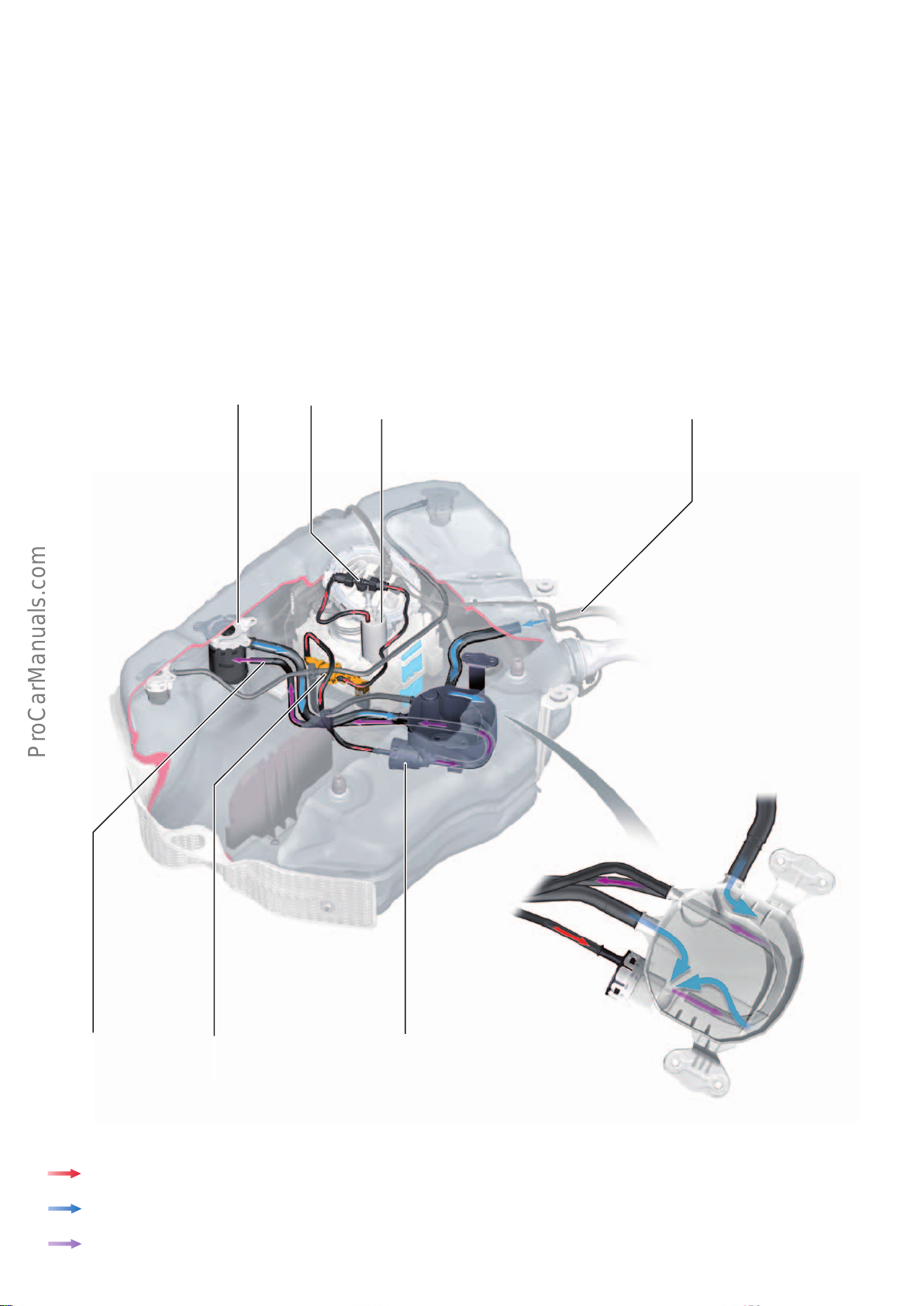
Tank ventilation system
< Back
Forward >
Ξ Contents
Due to the space constraints in new models, the tank ventilation
system has been revised. It was important to ensure that siphoning cannot occur in the line from the fuel filler neck to the activated carbon filter.
Petrol-engined models
Fuel vent valve
T piece
Fuel pump (pre-supply pump)
G6
The tank ventilation system is designed such that the fuel which
enters the vent line can be actively extracted from the liquid trap
while meeting the most stringent emission laws. The result is a
higher tank capacity and less air in the tank moulding.
Vent line to activated
carbon canister
Open-ended drainage outlet
Key:
Fuel system pressure from fuel pump G6
Non-return valve
Suction jet pump of
active extraction system
Liquid trap with active extraction system
Extraction
Fuel return to tank moulding
30
644_051
Page 31
Tank ventilation function
< Back
Forward >
Ξ Contents
Eects of failure of the tank ventilation system
The ventilation system is configured dierently depending on what
type of fuel is used.
The system requires a larger liquid trap for models with petrol
tanks due to the boiling characteristic of the fuel. The fuel which
has collected in the liquid trap is extracted by means of a suction
jet pump and drained o pressurelessly at the highest point in the
tank.
Diesel-engined models
Open-ended drainage outlet
Fuel pump (pre-supply pump)
G6
If one of the components of the ventilation system fails (lifetime
configuration), problems may occur during refuelling (refuelling
shut-o). A strong fuel odour could also be noticeable in petrolengined models (ACF canister flooding).
Vent line to
fuel filler neck
Liquid trap with active extraction system
Non-return valveFuel vent valve
Suction jet pump of
active extraction system
644_085
31
Page 32
SCR system
< Back
Forward >
Ξ Contents
Equalisation chamber
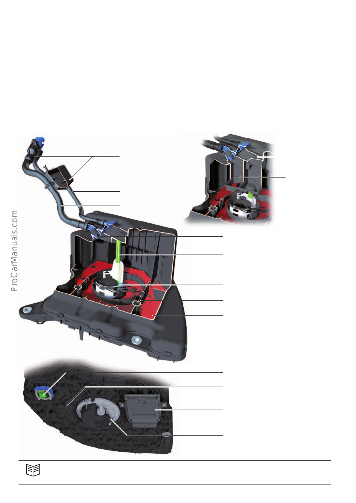
There are two dierent AdBlue® reducing agent capacity options
for the SCR system: a reducing agent tank with a capacity of
12litres and an optional tank for extended range with a capacity of
24litres.
The ventilation system within the reducing agent tank is designed
such that the tank can be filled with AdBlue® reducing agent using
pump nozzles. To be able to hold the reducing agent flowing into
the tank at a high flow rate, there is an equalisation chamber in the
vent line and in the filler neck. The returning reducing agent would
The capacity of the 12 litre reducing agent tank can be dierentiated by an extended filler tube and an extended vent line. A short
filler and vent line indicates a capacity of 24litres.
otherwise cause the pump nozzle to shut o too early.
To prevent the flow-back of reducing agent in the filler neck, a
non-return flap is installed at the end of the filler neck.
24litre version 12litre version
Reducing agent
filler neck
Equalisation chamber
Vent line
Filling line
Extended
vent line
Extended
filler line
644_011
Non-return flap
Reducing agent tank sender
G684
Swirlpot with reducing agent pump
V437
Baes
Reducing agent tank heater
Z102
644_007
Reducing agent quality sensor
G849 (initially available in NAR version only)
Outlet for draining the reducing agent
Reducing agent metering system control unit
J880
Swirlpot with reducing agent pump
V437
644_008
Reference
For more information about the SCR system, refer to Self Study Programme632 "AudiQ7 (type4M)".
32
Page 33
Engine/gearbox combinations
< Back
Forward >
Ξ Contents
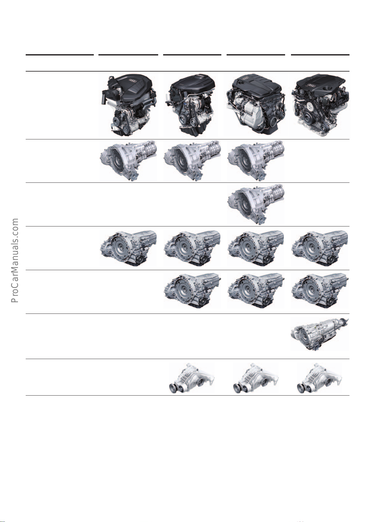
The engine-gearbox combinations shown below are those currently
available at market launch.
Engines 1.4l TFSI engine
(CVNA)
6-speed
manual gearbox 0DJ
ML322-6F
6-speed
manual gearbox
0CS
ML402-6F
7-speed
dual clutch gearbox
0CK
S tronic
DL382-7F
2.0l TFSI engine
(CVKB, CYRB)
2.0l TDI engine
(DEU..., DETA)
3.0l TDI engine
(CSWB, CRTC)
7-speed
dual clutch gearbox
0CL
S tronic
DL382-7Q
8-speed automatic
gearbox 0D5
tiptronic
AL552-8Q
Rear nal drive
0DB to 400 Nm
0D2 from 400 Nm
Breakdown of manufacturer codes:
e.g.: ML322-6F
A Automatic planetary gearbox
M Manual gearbox
D Dual clutch gearbox
L Longitudinal mounting
6 Number of gears
F Front-wheel drive
Q quattro all-wheel drive
(with integrated centre dierential)
322 Development number (provides information on torque
capacity, generation and position of front final drive etc.)
33
Page 34
Power transmission
< Back
Forward >
Ξ Contents
Overview
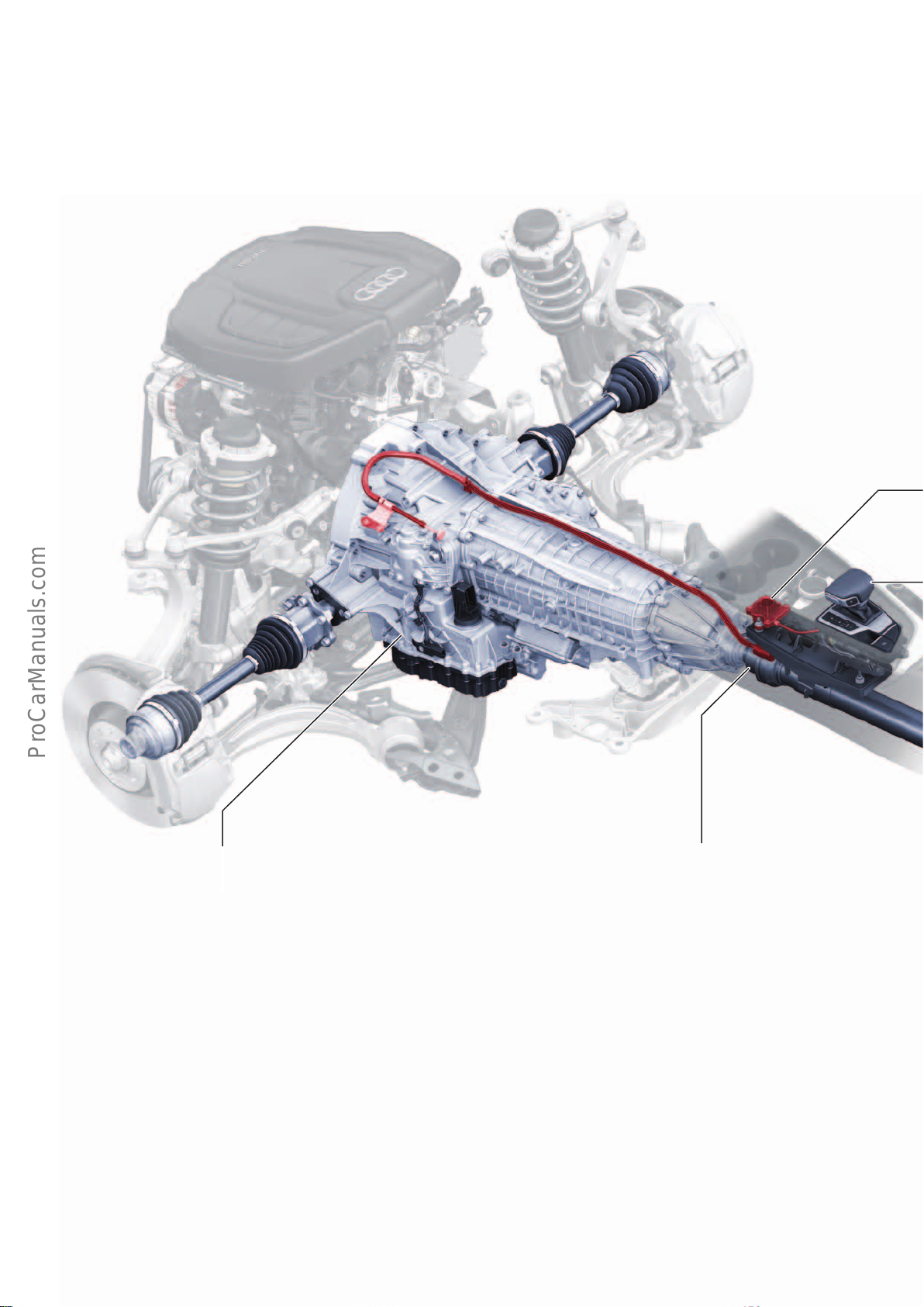
The Audi A4(type8W) employs the same drivetrain concept as the
preceding B8 series (type8K, 8T, 8F). The automatic and manual
gearboxes for front and all-wheel drive are new developments,
which have been installed previously in a slight dierent configura-
tion in the AudiA6ultra (type4G) and in the AudiQ7(type4M).
7-speed dual clutch gearbox 0CL
Depending on engine type, the following gearboxes will be available at start of production:
• 6-speed manual gearbox 0DJ – ML322-6F – front wheel drive
– refer to page 36
• 6-speed manual gearbox 0CS – ML402-6F – front wheel drive
– refer to page 36
• 7-speed dual clutch gearbox 0CK – Stronic – DL382-7F – front
wheel drive – refer to page 44
• 7-speed dual clutch gearbox 0CL – Stronic – DL382-7Q – all-
wheel drive – refer to page 44
• 8-speed automatic gearbox 0D5 – tiptronic – AL552-8Q
– all-wheel drive – refer to page58
Splined prop shaft
Assembly of the front prop shaft
The prop shaft is connected to the gearbox output shaft by a
spline.
For further information, refer to Self Study Programme457
"AudiA8’10 Power Transmission" and the AudiService TV pro-
gramme "AudiA8Power Transmission Part2/Topic: Splined Prop
Shaft" of 02.09.2010.
34
Page 35
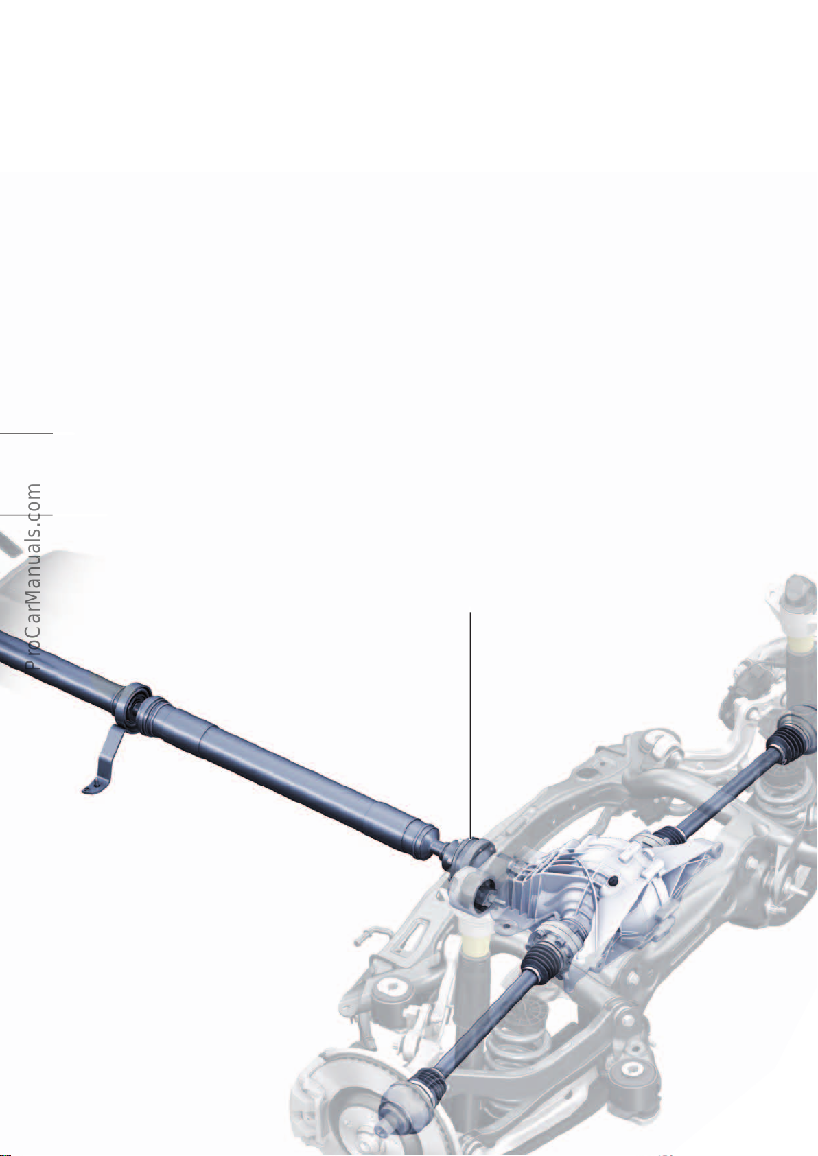
Rear axle transmission
< Back
Forward >
Ξ Contents
Standard
• Rear final drive 0DB – for engines with max. torque of up to
approx. 400Nm – refer to Self Study Programme 632 "AudiQ7
(type4M)", page 31
• Rear final drive 0D2 – for engines with max. torque of approx.
400Nm or higher
Optional
• Rear final drive 0D3 – sport dierential – to be used on AudiS4
for first time as of around Q2 2016
Emergency-releasing the parking lock – refer to page 56
Sport dierential 0D3 is an advancement on sport dierential 0BF.
The key modifications in sport dierential 0D3 are:
• Adaptation of the gearcase to the rear axle
• Welded crown wheel
• New axle oil and ATF
• Shortened sensors for more clearance to exhaust system
• The driving dynamics control system is integrated in the
suspension control unit J775 (no longer in the all-wheel drive
control unit J492). All that control unit J492 does is execute
the commands issued by J775.
• Various lightweight construction measures
For further information about sport dierential0BF, refer to
AudiService TV programme "Audi quattro with sport dierential",
Parts 1, 2, 3 and 4 as well as Self Study Programme476 "Rear final
drive 0BF/0BE - sport dierential".
Assembly of the rear prop shaft
Selector mechanism
The automatic gearboxes are operated by means of shift-by-wire and
park-by-wire technology – refer to page 40.
The procedure for attaching the prop shaft to the rear axle drive is
described in the bolting specification for triangular matching.
Refer to Workshop Manual.
For detailed information about triangular matching, refer to Self
Study Programme 409 and the AudiServiceTV programme
"AudiA5 Power Transmission /Topic: Prop Shaft Assembly
Concept" of 23.02.2010.
644_058
35
Page 36
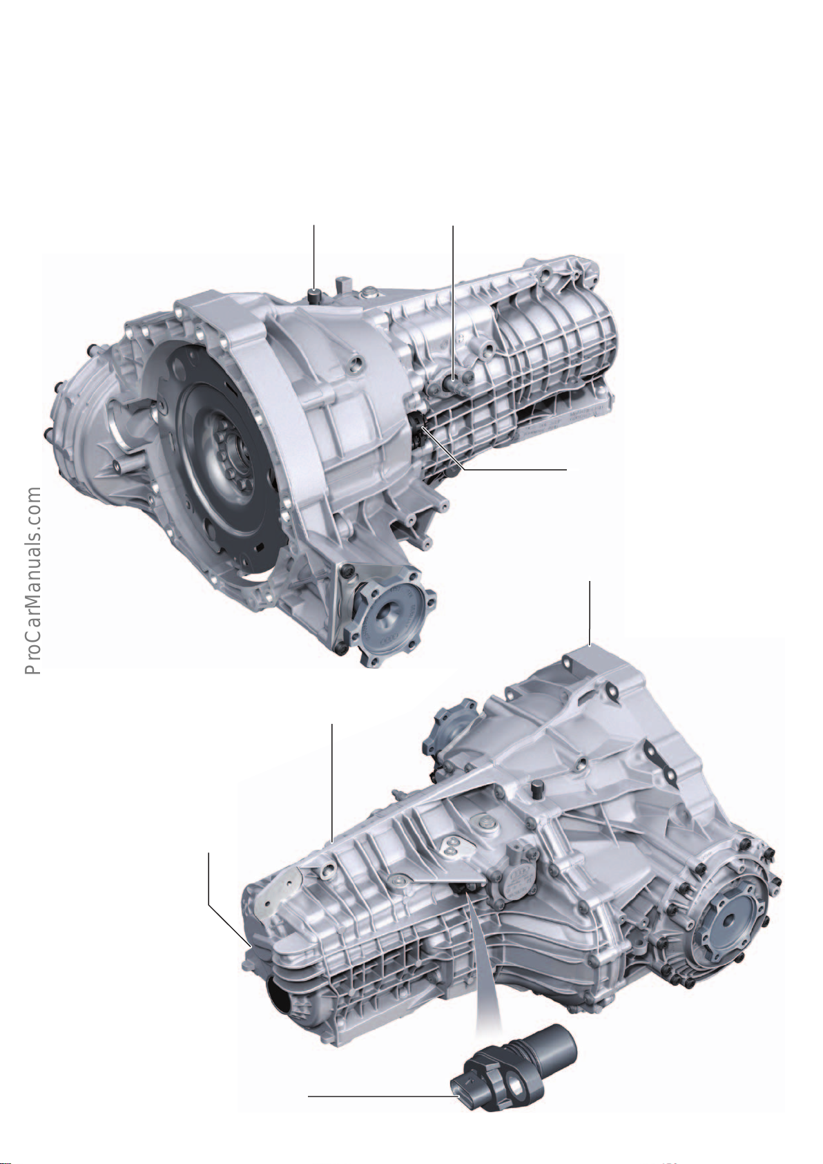
6-speed manual gearbox 0DJ/0CS
< Back
Forward >
Ξ Contents
The AudiA4 (type8W) features manual gearboxes which have
been specially designed for low weight, making optimal use of
installation space and improved eciency.
A key feature of these gearboxes is that they have no side shaft.
Gearbox vent Selector shaft
In addition to being significantly lighter, the gearboxes are very
narrow at the back. The slimline design reduces the width of the
body tunnel, which in turn frees up space in the driver and front
passenger footwells.
Hydraulic connection and vent screw of
clutch slave cylinder
644_059
Gearcase back – gearbox cover:
• Made of magnesium in 0DJ and 0CS gearboxes
A manual gearbox will be available at a later date
for quattro all-wheel drive.
It stems from the same gearbox series and will
have the designation 6-speed manual gearbox 0CX.
Gearcase front end:
• Made of magnesium in 0DJ gearbox
• Made of aluminium in 0CS gearbox
In models with the 0DJ / 0CS gearbox,
maximum speed is reached in 5th and/or
6th gear, depending on engine type.
Gear recognition sensor G604
• For information about G604, refer to
Self Study Programme486 "Audi A6’11", page 32 .
644_060
36
Page 37
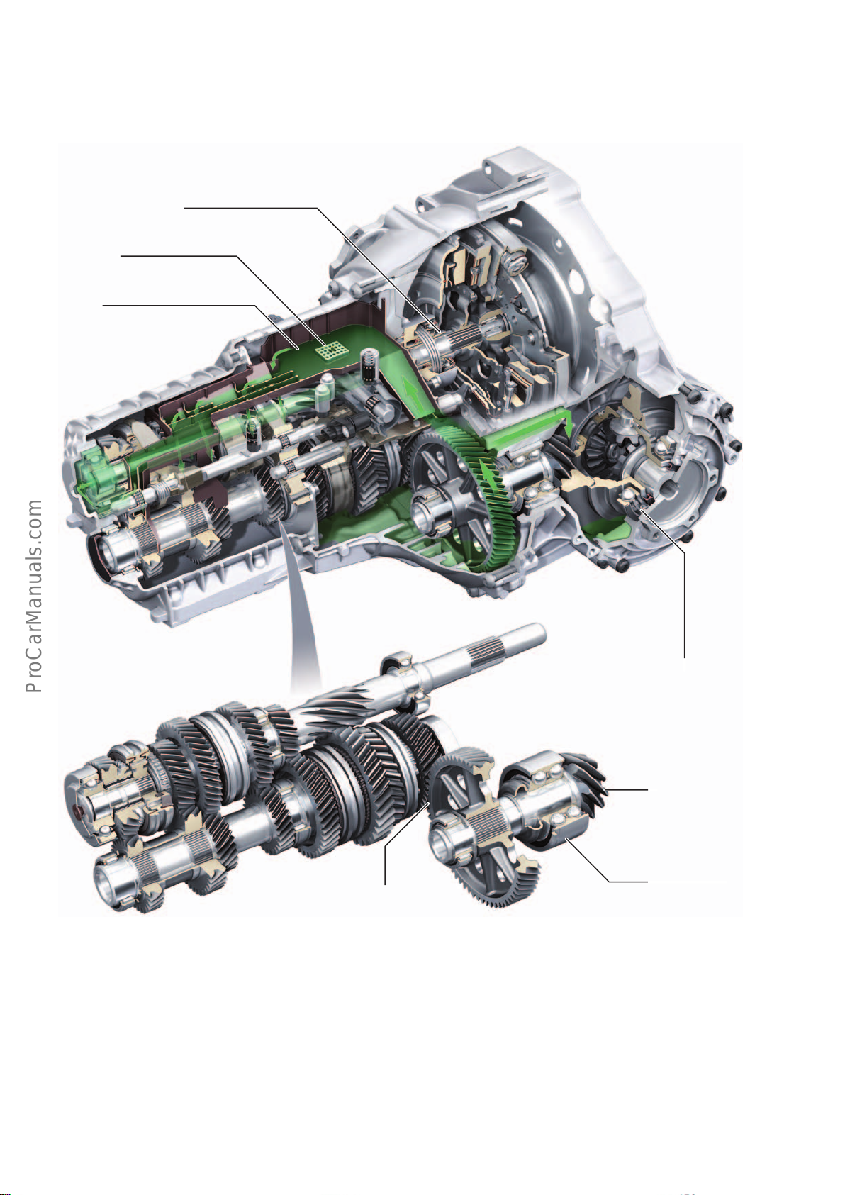
6-speed manual gearbox 0DJ and 6-speed manual gearbox 0CS are
< Back
Forward >
Ξ Contents
identical in design and dier from one another principally in terms
of the material used in manufacturing the front gearcase. The two
gearcases for the 0DJ gearbox are made of magnesium. In the case
of the 0CS gearbox, the front gearcase is made of aluminium and
the rear gearcase (gearbox cover) is made of magnesium.
Concentric clutch disengagement system
Permanent
magnet
Oil pan
The 0DJ gearbox with its two magnesium gearcases is lighter, while
the 0CS gearbox has a higher torque capacity due to its aluminium
front gearcase.
Gear set of 0DJ / 0CS gearbox
Spur gear step
The special oiling concept of the gear set allows for a low oil fill
quantity. It also allows the vehicle to run at a much lower oil level,
while significantly reducing churning and drag losses. To achieve
this, the spur gear of the pinion shaft conveys the gear oil (ATF)
into the oil drip pan, which in turn distributes it to the lubrication
points.
The oiling concept, a new low-viscosity MTF and friction-optimized
gear set bearings provide much better eciency and significantly
reduce fuel consumption.
Dierential cage mounted
in ball bearings
Drive pinion
Double row angular contact
ball bearings
644_061
Power is transmitted to the pinion shaft through a low-loss spur
gear step. The short pinion shaft runs at right angles to the crown
wheel, and there is no axial oset. This permits the use of lowfriction spiral teeth and low-viscosity MTF (gear oil) in the bevel
gear. In addition, the final drive can be repaired by service centres
in the conventional way.
Double row angular contact ball bearings are used as fixed bearings in the pinion shaft, minimising prestress in the bearings and
enabling the bearings to run smoothly.
37
Page 38
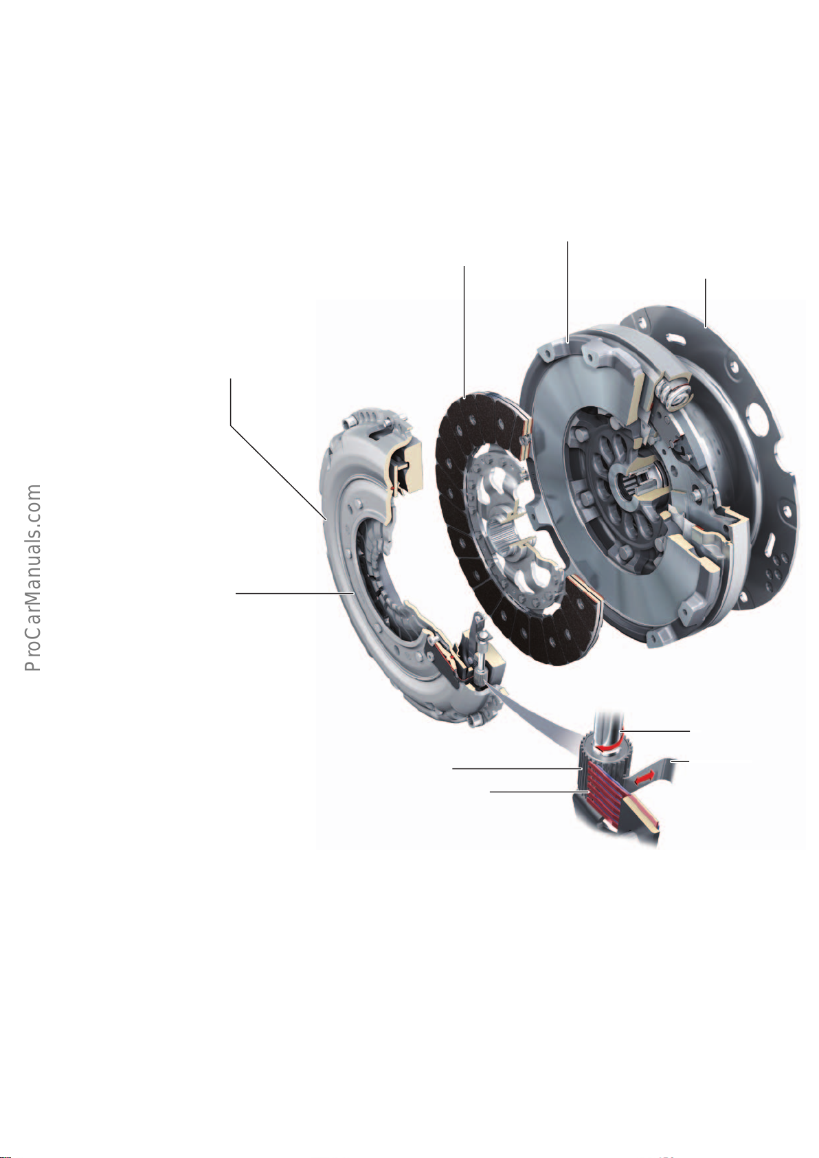
Clutch module
< Back
Forward >
Ξ Contents
The clutch modules are specially configured to meet the dierent
requirements of the various engine versions.
The 0DJ gearbox in combination with the 1.4l TFSI engine features
a clutch module with a conventional dual-mass flywheel (DMF) and
a non-self-adjusting clutch pressure plate.
All other engine versions have self-adjusting clutch pressure plates
and a DMF with a centrifugal pendulum-type absorber.
There are three versions of the clutch pressure plate:
• Non-self-adjusting clutch pressure plate
• SAC clutch pressure plate (self-adjusting)
• TAC clutch pressure plate (self-adjusting)
The AudiService TV programme "Dual mass flywheel with centrifugal pendulum absorber" of 16.01.2015 explains the functional
principle of these dual-mass flywheels and provides practical
advice for workshop personnel.
The Audi Service TV programme "AudiA5Power Transmission" of
23.02.2010 deals in depth with the clutch module.
Dual mass flywheel with and
without centrifugal pendulum-type absorber
Clutch plate
Transmission plate
• Pay attention to correct order of assembly.
The self-adjusting clutch pressure plates
by LuK are currently available in two different versions - the SAC clutch pressure
plate and the TAC clutch pressure plate.
SAC clutch pressure plate
SAC stands for "Self Adjusting Clutch". The SAC system is dependent on release force. In the SAC system, the clutch pressure plate
can be reset after it has been adjusted to compensate for wear.
Refer to Workshop Manual. This allows the clutch disc and the
clutch pressure plate to be replaced individually.
For more information about the SAC, refer to Self Study Programme198 "The 2.7l V6 biturbo".
TAC clutch pressure plate
TAC stands for "Travel Adjusting Clutch". The TAC system works by
adjusting its release travel according to clutch wear. In the TAC
system, the clutch pressure plate cannot be reset after it has been
adjusted to compensate for wear. Refer to Workshop Manual. The
clutch disc and clutch pressure plate may only be replaced
together. The TAC clutch is used on models with higher torque
engines because the TAC system is less susceptible to axial vibration.
Ratchet mechanism
of the TAC clutch pressure plate
Threaded spindle
Pinion
Anti-reversing
lock
Drive pawl
644_062
Function
Travel is adjusted during the engagement and disengagement of
the clutch. If the distance between the friction faces of the clutch
pressure plate and the DMS decreases due to clutch wear, the
release travel of the clutch changes accordingly. This change in
travel activates a ratchet mechanism which is coupled with a
threaded spindle and rotates the ramp ring, thereby compensating
for wear. Further information about the TAC is available on the
internet.
38
Page 39
Clutch control
< Back
Forward >
Ξ Contents
Advantages of the CSC clutch release mechanism:
The new gearbox series is equipped with a so-called CSC clutch
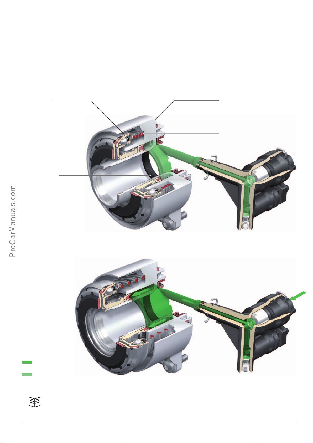
release mechanism. CSC stands for "Concentric Slave Cylinder". The
clutch slave cylinder and the release bearing form a functional unit
and can only be replaced together.
Clutch not actuated / clutch engaged
Release bearing
Oil seal for gearbox
input shaft
• Fewer moving parts and constant actuation forces over the
lifetime of the clutch
• Exact axial clutch release improves clutch release and engagement (enhanced comfort).
• Minimum installation space requirements
Clutch slave cylinder
Preload spring
Clutch actuated / clutch disengaged
Key:
Clutch pressure
Depressurised
644_063
644_064
Reference
For detailed information about the function, design and service-related aspects of the 0CS gearbox in the AudiA6ultra
(type4G), refer to the AudiService TV programme "6-speed manual gearbox 0CS – front wheel drive / service information" of
14.03.2014.
39
Page 40
Automatic gearbox selector mechanism
< Back
Forward >
Ξ Contents
Basic shift schematic
The AudiA4 (type8W) employs the latest generation Audiselector
mechanism with full shift-by-wire capability (SBW). This means
that parking lock operation is also fully automatic. The term used
for this is "park-by-wire" (PBW). There is no selector cable connecting the selector mechanism to the gearbox. This selector mechanism was previously used in the AudiQ7(type4M) and in the
AudiR8(type4S) and will also be used in the future C series.
The operating concept is highly intuitive and is essentially identical
to the familiar operating logic of automatic gearbox models. After
every operation, however, the selector lever always returns to the
normal position of the automatic or tiptronicgate.
The parking lock normally engages and disengages automatically
via the Auto-P function, but can also be engaged manually by the
driver using the P button.
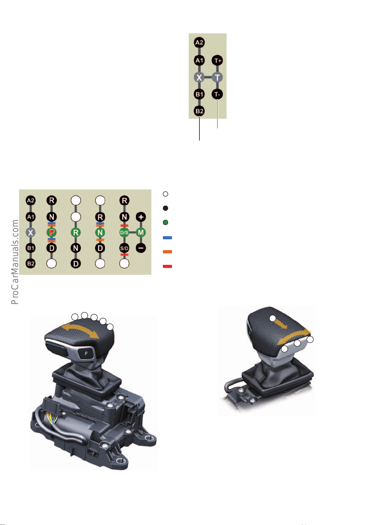
Shift schematic
Possible positions of the selector lever. Normal
position X in automatic mode or normal
position T in tiptronicmode.
Depending on the selector lever position, this
position information (A1, A2 etc.) is displayed
in the measured data of the diagnostic tester.
644_065
tiptronic gate
Automatic gate
Positions selectable without moving the selector
Selectable drive positions
Normal position of the selector lever and current drive position
Software lock: deactivate by pressing the release button E681
Software lock: deactivate by pressing the foot brake
Mechanical locking by selector lever lock solenoid N110 –
deactivate by pressing the release button E681
644_066
Note: An acknowledgement tone sounds when drive position R is
engaged.
Automatic gate tiptronic gate
A1
A2
X
B1
B2
1)
X
T+
T
T-
644_068
Speed-dependent gearbox protection function
A change in driving direction from forwards to reverse and vice
versa is only possible up to a driving speed of about 8kph with the
AL552 gearbox and up to about 15kph with the DL-382 gearboxes.
When this speed threshold is exceeded, a gearbox protection
644_067
1)
The orange-coloured software lock is activated in drive position N after about one second. This allows quick-changing of the drive position
function prevents prevents direction reversal.
from D to R and vice versa without applying the brake. The makes it possible, for example, to free a stuck vehicle by rocking it backwards
and forwards and makes it easier to change gear when manoeuvring the vehicle.
40
Page 41
Component overview
< Back
Forward >
Ξ Contents
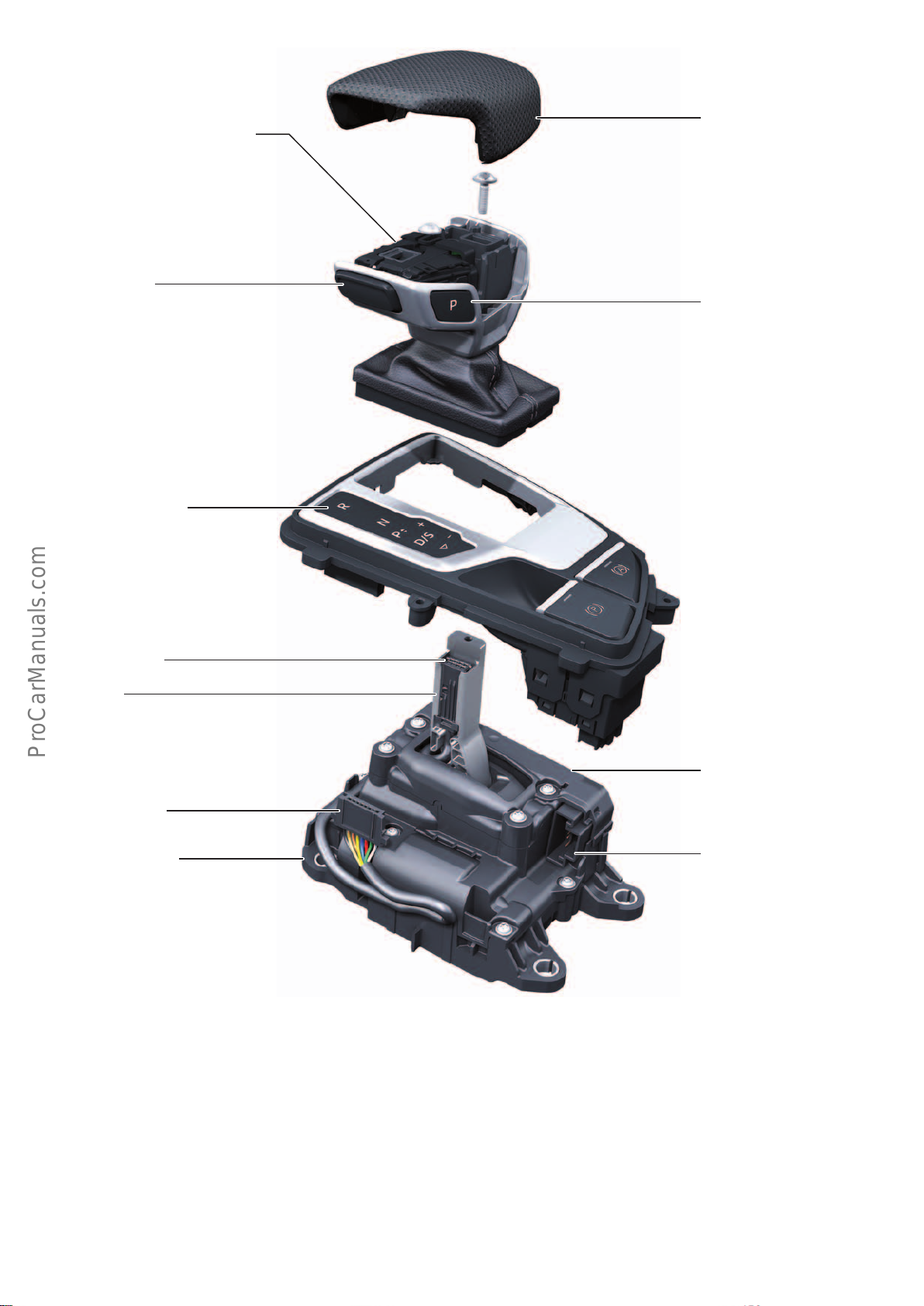
Handle for selector lever
bottom section with selector lever
gaiter
Selector lever
release button
E681
Selector lever position
display
Y5
Handle for selector lever
upper section
P button –
parking lock button E816 with
parking lock warning light K320.
K320 illuminates the P button in
a dimmed fashion and is brightly
lit when the parking lock is
active.
Plug connection E
Selector
lever
Plug connection C
Selector mechanism
(selector lever E313)
Selector lever release button E681 – release button Parking lock button E816 – P button
Button E681 is used to deactivate the software lock, which is
highlighted blue in Fig. 644_066, and to release selector lever lock
N110. It consists of two shift elements for reliability and diagnostics. In the event of a fault, release button E681 is considered
actuated.
The locks marked red and blue (Fig. 644_066) are disabled. A fault
is registered in the event memory and indicated in the instrument
cluster. To move the selector out of drive positions P and N, the
brake pedal must be pressed in addition to the release button.
The P button is for manually deactivating the parking lock. The
parking lock can only be activated if the vehicle is travelling at a
speed of <xkph (AL552 <3kph, DL382 <2kph (<1kph with
Auto-P function)). Button E816 comprises three shift elements for
reliability and diagnostics. Its shift status is transferred to the
selector lever sensors control unit J587 via two interfaces. In the
event of a fault in E816, a message appears in the instrument
cluster and the parking lock can only engaged by the Auto-P
function.
Selector lever sensors
control unit
J587
Plug connection A
644_069
41
Page 42
Information exchange
< Back
Forward >
Ξ Contents
Information flow
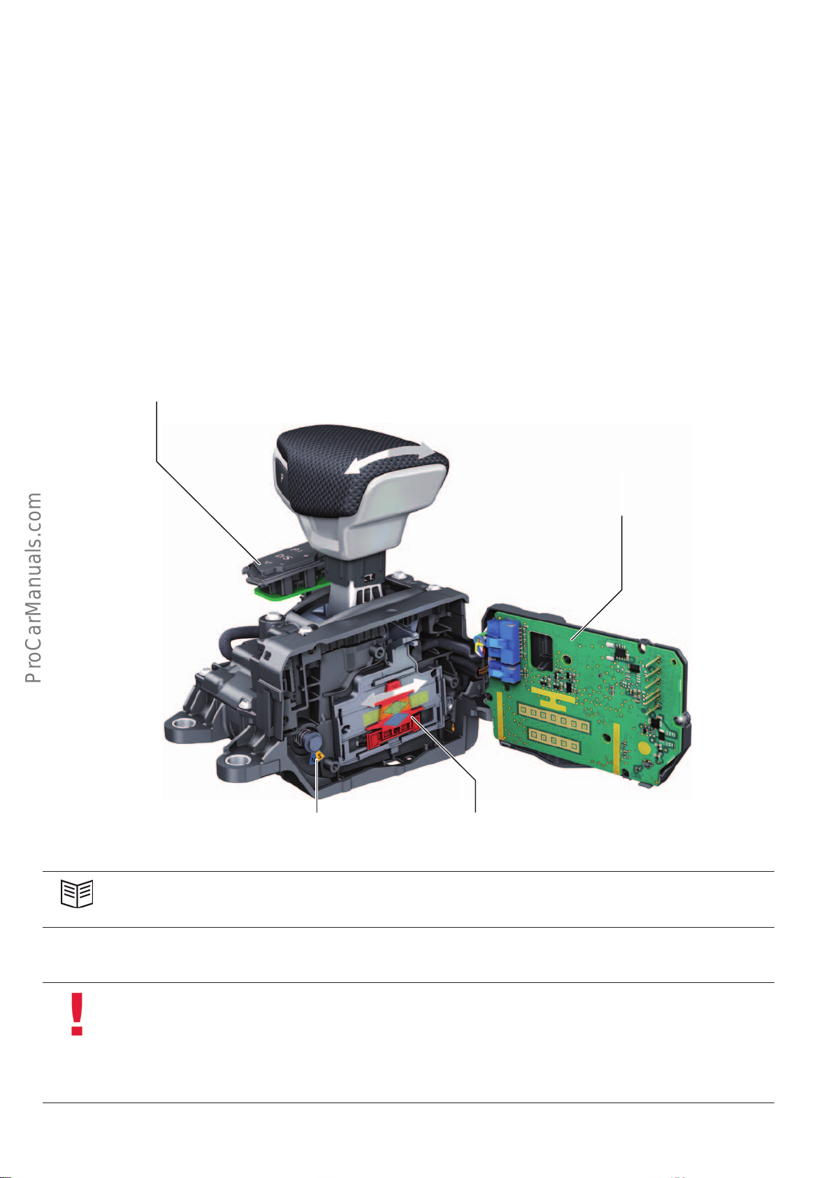
Data is exchanged between the selector mechanism and the
gearbox through the gateway. The selector lever sensors control
unit J587 communicates with the infotainment CAN, the gearbox
control unit J217 and the FlexRay.
In the event of a system malfunction in J587 after which the
gearbox cannot be operated using the selector mechanism, drive
positions P, R, N and D can be selected by simultaneously operating both shift paddles while the vehicle is stationary and with the
brake applied.
Selector lever position display
Y5
J587 registers the positions of the selector lever as well as the
signals from both buttons and sends this information on to the
gearbox control unit. The gearbox control unit engages the gear
corresponding to the driver input and sends this information on to
J587. The selector lever control unit then activates the corresponding selector lever locks (N110/V577), the selector lever position
display LEDs Y5 and the parking lock warning light K320. When a
gear is selected, this information flow process involves a short
delay until the corresponding gear symbol lights up.
Special feature of the dual clutch gearboxes
In the AudiA4(type8W) with dual clutch gearboxes of the DL382
series, J587 has two additional interfaces for controlling the
parking lock holding magnets N486. Refer to function diagram and
page 48 .
Selector lever sensors control unit J587
with selector lever position sender G727 and
transverse selector lever lock sender G868
Reference
For further information about the selector mechanism, refer to Self Study Programme643 "7-speed dual clutch gearbox 0BZ
- Stronic in the AudiR8 (types42 and 4S)".
1)
Note
In the case of the 0D5 gearbox (AL552), the parking lock can only be disengaged (P-OFF) when the engine is running because
the 0D5 gearbox uses a mechanical-powered ATF pump which only conveys ATF when the engine is running.
In the case of the DL382 gearboxes, the engine does not have to be running to disengage the parking lock (P-OFF). That is
because this gearbox is supplied with ATF by an electric-powered ATF pump and a pressure accumulator. This means that the
supply of ATF is not dependent on engine operation and that the parking lock can be disengaged when the ignition is on.
644_070
Sender element for G727Sender element for G868
42
Page 43
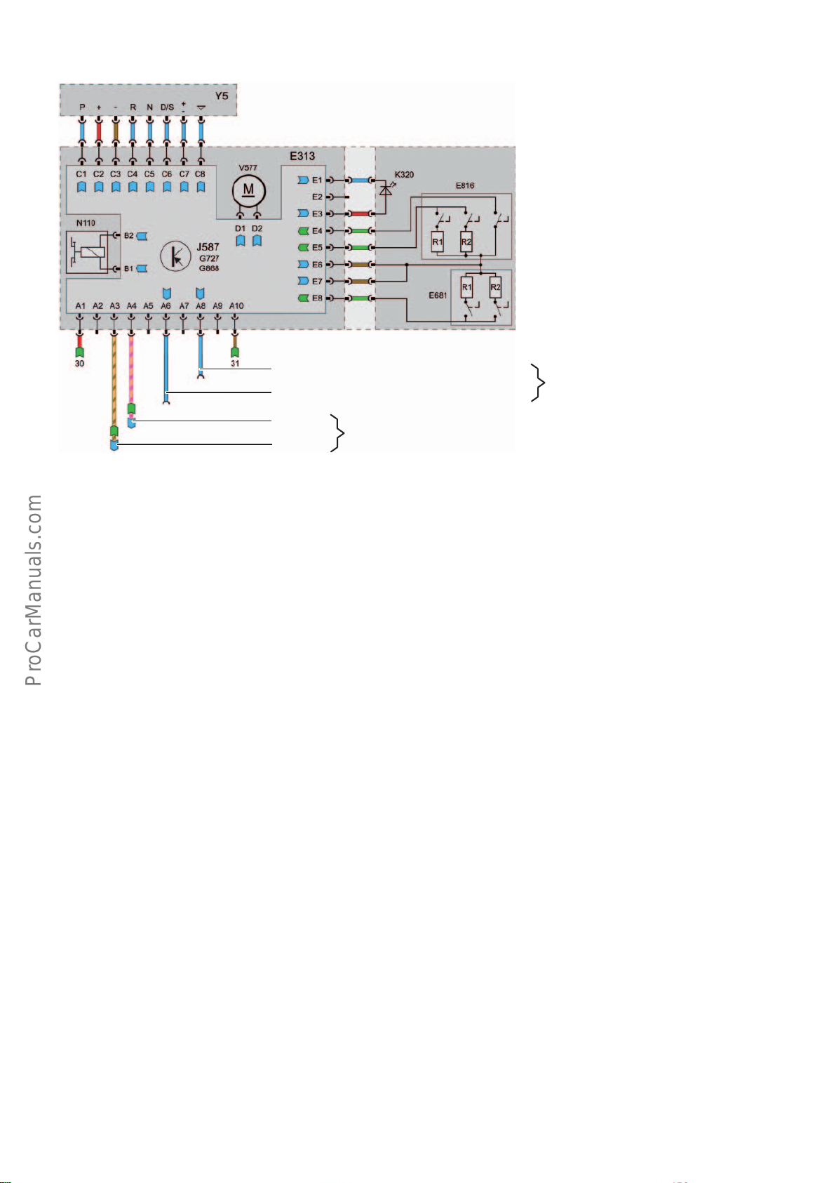
Function diagram – selector mechanism
< Back
Forward >
Ξ Contents
Key:
E313 Selector lever (selector mechanism)
E681 Selector lever release button
E816 Parking lock button
G727 Selector lever position sender
G868 Transverse selector lever lock sender
J587 Selector lever sensors control unit
K320 Parking lock warning light
N110 Selector lever lock solenoid
V577 Transverse selector lever lock motor
Y5 Selector lever position display
Interface to parking lock holding magnet + (pinA1)
Interface to parking lock holding magnet - (pinA2)
CAN-High
CAN-Low
Infotainment CAN
Auto-P function
In the case of the automatic gearboxes, the parking lock is electrohydraulically operated. This allows the gearbox control unit to
automatically operate the parking lock, thereby enhancing operating comfort.
The Auto-P function engages the parking lock automatically (P-ON
position) if all of the following conditions are met:
• Vehicle stationary – speed < 1 kph
• Driving position E, D, S, R or M is selected
• Engine is not running – terminal 15 OFF
Activating drive position N (P-OFF position)
To be able to briefly move the vehicle without the parking lock,
e.g.in a car wash, automatic engagement of the parking lock can
be suppressed.
A condition for this is that the selector mechanism, the P button
and the gearbox are working properly.
The following applies to vehicles with the AL552 gearbox (tiptronic):
To activate P-OFF, drive position N must be selected when the
engine is running and then the engine must be shut o. When the
ignition is turned o, engagement of the parking lock is suppressed for a period of 30 minutes.
The following applies to vehicles with the DL382 gearbox
(Stronic):
In the case of the DL382 gearboxes, the P-OFF position can be
engaged with or without the engine running. To activate P-OFF,
drive position N must be selected after turning the ignition on.
The parking lock is now disengaged (P-OFF) and engagement of
the parking lock is suppressed for a period of 30minutes after
turning the ignition o.
1)
Only available in the AudiA4 (Typ8W) in combination
with dual clutch gearboxes of the DL382 series. Refer
to page 49.
644_071
In the AudiA4(type8W), the drievr can also engage the parking
lock by pressing the P button as soon as the vehicle is travelling
slower than 2kph (DL382) or 3kph (AL552).
The parking lock is disengaged automatically (P-OFF position) if
the engine is running and drive positionE, D, S, R, N or M is
selected with the brake applied and the release button pressed.
The following applies to all gearboxes:
After 29 minutes the following message is displayed in the instrument cluster: "Start engine to remain in N." along with a warning
tone. If this instruction is not followed, the parking lock engages
after 30 minutes and the system shuts down.
If a speed signal (v>1kph) is detected during this time, the period
is extended according to the driving time of the vehicle until the
system detects that the vehicle has been stationary for at least
5minutes.
During the stopping period in the P-OFF position, electrical power
is consumed by the activity of the control unit, bus operation and
the holding magnet. If the vehicle is held stationary for a lengthy
period of time, the battery may become discharged to the extent
that the parking lock automatically self-engages.
If it is necessary to hold the parking lock in the P-OFF position for a
longer period of time, the parking lock emergency release mechanism must be actuated (refer to page 48). Refer to page 56.
43
Page 44
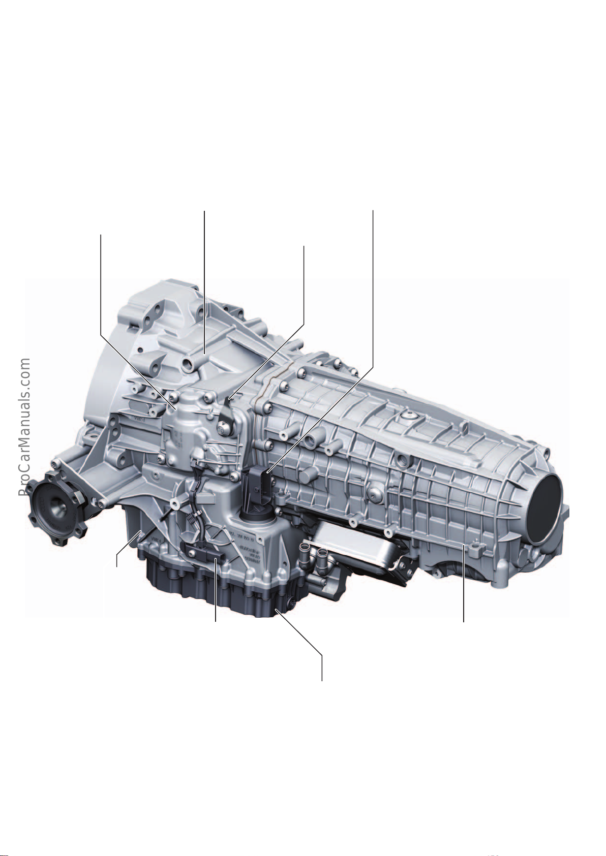
7-speed dual clutch gearbox 0CK/0CL – Stronic
< Back
Forward >
Ξ Contents
Both 7-speed dual clutch gearboxes are advancements on the 0CK
gearbox which was launched in the AudiA6ultra(type4G) in mid
2014.
The functions of the 0CK gearbox were extended for the
AudiA4(type8W) and various improvements were implemented.
7-speed dual clutch gearbox 0CK – front-wheel drive
Combined gearbox ventilation system for
the ATF and MTF systems
Parking lock module – refer to page 48
1)
Gearbox selector lever for emergency-releasing
the parking lock – refer to page 56
Key new features are a variant for quattro all-wheel drive, the
shift-by-wire technology and the electrohydraulically operated
parking lock with park-by-wire technology.
A striking feature of the new S tronic gearboxes is the ATF pan
made of black plastic.
Electrical connection for the mechatronics and
automatic gearbox control unit J217
Separate ATF system with ATF
supply independent of engine
operation
Electrical connection for the parking lock solenoid N486
• Parking lock holding magnet – refer to page 48
1)
1)
For detailed information about the function, design and
service-related aspects of the 0CK gearbox in the
AudiA6ultra(type4G), refer to the following AudiService
TV programmes:
• 7-speed dual clutch gearbox 0CK – Stronic Part1
Design and function of 26.10.2014
• 7-speed dual clutch gearbox 0CK – Stronic Part2
Service and practical advice for workshop personnel of
26.10.2014
• Dual mass flywheel with centrifugal pendulum-type
absorber of 16.01.2015
644_072
Separate MTF system, dry sump
lubrication system with MTF pump
Plastic ATF pan
• The gearbox must be set down onto the ATF pan with care and over a large
area. To ensure that the MTF pump cannot become damaged, the gearbox
must be secured against tilting backwards. Refer to Workshop Manual and
AudiService TV programme Part 2.
1)
44
Page 45
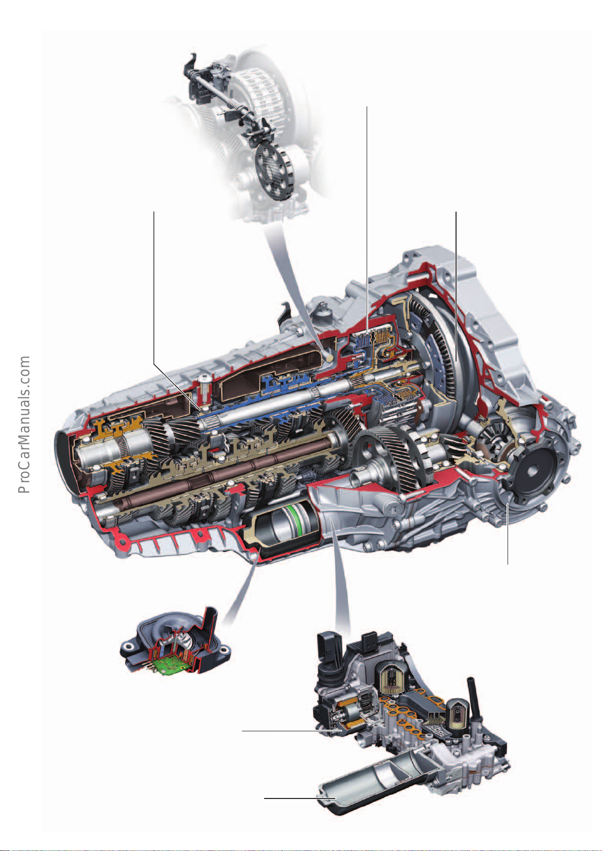
Special features at a glance
< Back
Forward >
Ξ Contents
shift-by-wire and park-by-wire
technology
Innovative features of the dual clutch gearbox1):
• Clutch operation with stationary central engagement system
(without rotary union)
• Active clutch plate separation
• Separate clutch cooling system
Low-friction bearing concept
of gear set for increased eciency
1)
Dual mass flywheel with
centrifugal pendulum-type absorber
1)
Dry sump lubrication system for
the gear set and MTF pump
• Electrical gearbox
pump2 V553
1)
Electric-powered tandem ATF pump
• Electrical gearbox pumpV552
Rear axle final drive without hypoid oset
1)
Mechatronic unit with demand-responsive, full-time ATF supply independent of
engine speed by means of an electrical
ATF pump and pressure accumulator
1)
concept
1)
Pressure accumulator (gas pressure hydraulic
accumulator)
1)
• Note: follow the safety instructions given in
the Workshop Manual.
644_073
45
Page 46
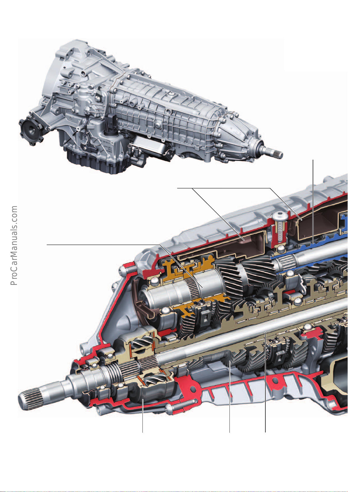
7-speed dual clutch gearbox 0CL – all-wheel drive
< Back
Forward >
Ξ Contents
644_074
MTF supply pan
The quattro version – 0CL is, apart from the all-wheel drive component set, absolutely identical to the front wheel drive version – 0CK.
Input shaft 2
Input shaft 1
Self-locking centre dierential with asymmetric-dynamic engine torque split
– refer to Self Study Programmes429 "AudiQ5 - Engines and Transmissions"
page 22 . and 632 "AudiQ7 (type4M)", page 32 .
The self-locking centre dierential comes in dierent versions (dierent
manufacturers). The characteristics of both versions are identical.
46
Input shaft for
sub-gearboxes 1 and 2
The input shaft within the output shaft for
sub-gearboxes 1 and 2 connects to the spur
gear step of the front final drive
Page 47
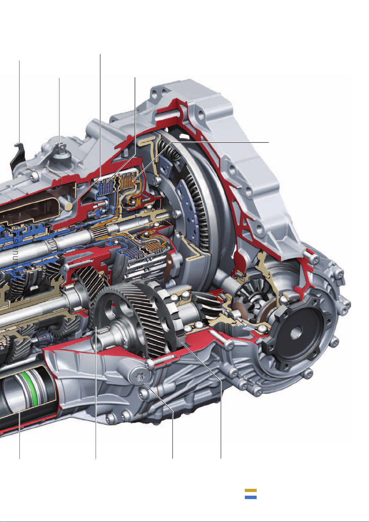
In models with the 0CK or 0CL gearbox, top speed is in 6th gear. In
< Back
Forward >
Ξ Contents
7th gear engine speed is reduced for better fuel economy. Refer to
information on page 62.
Gear shift lever for
parking lock emergency release
Parking lock module
Selector shaft for parking lock
Clutch K2
Clutch K1
Pressure accumulator
(gas pressure hydraulic
accumulator)
Note: please follow the
safety instructions given
in the Workshop Manual.
Spur gear step
– front final drive
MTF filler and
inspection screw
644_075
Parking lock gear
Key:
Gearbox input, sub-gearbox 1
Gearbox input, sub-gearbox 2
47
Page 48
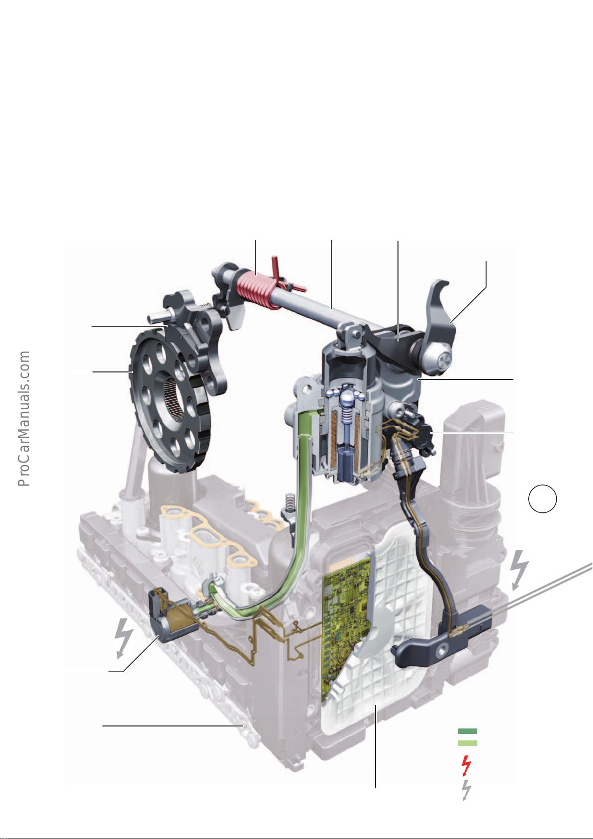
park-by-wire (PBW) parking lock
< Back
Forward >
Ξ Contents
Parking lock for 7-speed dual clutch gearbox 0CK/0CL
The 0CK and 0CL gearboxes belong to the DL382 series. The DL382
is available with a manual, cable-operated parking lock
(AudiA6ultra, type4G) and now, in the AudiA4(type8W), with an
electrohydraulically operated parking lock (park-by-wire).
The basic working principle of the parking lock mechanism has
been retained and extended to include the necessary electrohydraulic components.
The mechatronic unit was developed on the basis of the design
chosen for the DL382 shift-by-wire und park-by-wire system. There
are therefore no major dierences between the mechatronic unit
and the manually operated mechanical system.
Parking lock spring Selector shaft Parking lock lever Gear selector lever for
Pawl with spring
Parking lock gear
The main feature of the system in the AudiA4 (type8W) with
DL382 series dual clutch gearboxes is that the parking lock is not
solely controlled by the mechatronic unit; the selector mechanism
is also actively involved. Control unit J587 (selector mechanism)
activates the parking lock holding magnets, while the automatic
gearbox control unit J217 controls the parking lock. Refer to
function chart on page 49.
emergency-releasing the
parking lock – refer to page 56
Gear sensor
G676
Solenoid valve 6 – N93
VSS valve accumulator
points
Mechatronic unit
J743
Parking lock module
1
644_095
Key:
Electrohydraulic
control unit
(control valve assembly)
48
Automatic gearbox control unit
J217
System pressure
Depressurised
Energised
De-energised
Page 49
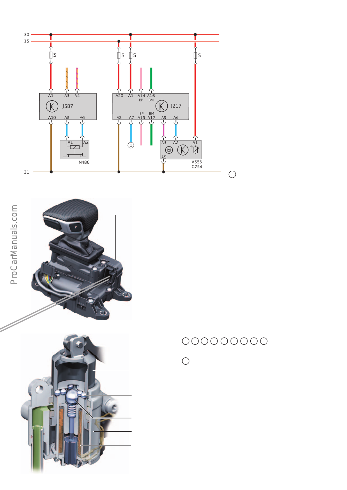
Function plan – 0CK/0CL gearbox with park-by-wire
< Back
Forward >
Ξ Contents
Infotainment CAN
Selector
mechanism
FlexRay
IN
FlexRay
OUT
LIN
Gearbox
Information is exchanged between the
selector mechanism and the gearbox via the
gateway by means of the infotainment CAN
and the FlexRay bus – refer to page 84.
Key:
G754 Gearbox oil temperature sensor 2
– MTF temperature sensor
J217 Automatic gearbox control unit –
gearbox control unit
J587 Selector lever sensors control unit
N486 Parking lock solenoid
– Parking lock holding magnet
V553 Electrical gearbox pump2
– MTF pump
BP FlexRay Bus Plus
BM FlexRay Bus Minus
Selector mechanism
Parking lock module
Selector lever sensors
control unit
J587
644_038
1
Starter control signal
(P/N signal)
Function
The parking lock is engaged mechanically by spring force alone
(P-ON). The parking lock module is disengaged (P-OFF) by hydraulic pressure produced by the mechatronic unit. A special locking
mechanism integrated in the piston of the parking lock module
additionally secures the parking lock in the P-ON or P-OFF position
and increases the operating reliability of the park-by-wire system.
Refer to page 54.
The core of the locking mechanism is the parking lock solenoid
N486. N486 is activated by the selector mechanism (J587) as
commanded by the gearbox control unit (J217). J587 provides
feedback to J217 on the actual status of N486. J217 and J587
communicate with one another bidirectionally via the gateway by
using the FlexRay and CAN infotainment buses.
The various functional states of the parking lock and the parking
lock module are shown below:
1
2A 2B
4A 4C 4D
3
4B
4E
644_077
Parking lock piston
Locking balls
Central ball
Parking lock cylinder
Parking lock solenoid N486
– Parking lock
holding magnet
Parking lock engaged (P-ON) – refer to Fig. 644_095
1
Starting scenario
The vehicle is shut o (the bus is at idle) and the parking lock is
engaged (P-ON).
The entire hydraulic system is depressurised and de-energised. In
the de-energised state of N93, the inlet from the parking lock
cylinder to the oil sump is open. The parking lock spring pushes the
locking pawl into the tooth gap in the parking lock gear and the
holds the parking lock in the ON position.
The parking lock holding magnet is inactive. The locking balls do
not have a locking eect because the central ball does not exert
any force on the locking balls.
49
Page 50
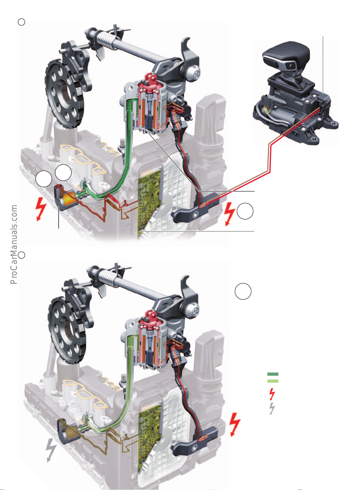
2
< Back
Forward >
Ξ Contents
Parking lock disengaged (P-OFF)
2B
2A
Selector lever sensors control unit
J587
2B
Solenoid valve 6
N93
Keep parking lock disengaged by activating drive position N (time-limited P-OFF position – refer to page 43)
3
3
1)
Note: The parking lock module is only
depressurised in N after ignition OFF
(special function for workshops/car
washes). After N is selected and the
ignition is turned on, system pressure
is applied to the parking lock module.
Parking lock solenoid – N486
– parking lock holding magnet
Automatic gearbox control unit
J217
644_086
1)
Key:
System pressure
Depressurised
Energised
De-energised
644_087
50
Page 51
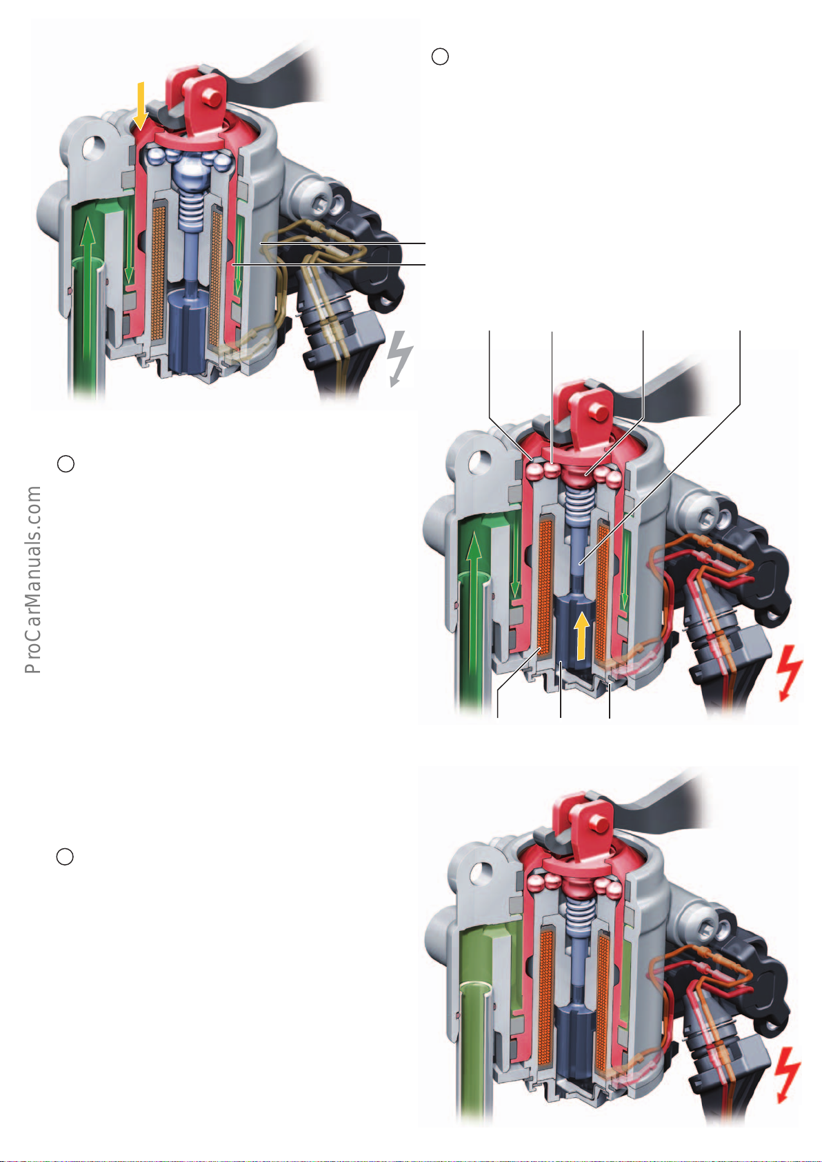
Disengage parking lock (P-ON --> P-OFF)
< Back
Forward >
Ξ Contents
2A
To disengage the parking lock, the parking lock holding magnet
(N486) is first deactivated. Afetr this, the gearbox control unit
J217 energises solenoid valve 6 N93, whereupon it directs the
system pressure to the parking lock cylinder. The piston force is
greater than the force of the parking lock spring. The parking lock
is disengaged. If the P-OFF position is detected by gear sensor
G676, the parking lock holding magnet is activated – refer to (2B).
Parking lock cylinder
Parking lock piston
Keep parking lock disengaged (P-OFF)
2B
In the P-OFF position, oil pressure is continuously applied to the
parking lock piston – refer to (3) for exception. To safeguard
against an unwanted pressure drop, the parking lock piston is
additionally locked with the aid of a locking mechanism. This
locking mechanism is actuated by the parking lock magnet N486,
which, in turn, is activated by the selector lever sensoes control
unit J587.
Function – locking mechanism / parking lock holding magnet
The armature is pulled into the coil by energising N486. The
armature pushes the central ball upwards with the tappet, with
the result that the locking balls are pushed into and held in the
P-OFF annular groove as long as N486 is energised. To activate the
lock, N486 is initially energised by applying approx. 1.2 A. To hold
the lock, the current is reduced to approx. 620 mA. This prevents
the coil from overheating and reduces power consumption.
644_088
Annular groove P-OFF
Coil Armature
Locking balls
Tappet with springCentral ball
Parking lock solenoid – N486
Parking lock holding magnet
644_089
Keep parking lock disengaged by activating drive position N
3
The P-OFF position can be maintained by selecting drive position N
before turning o the ignition or before shutting o the engine
(bypassing the Auto-P function). After turning the ignition o, the
selector levers control unit J587 remains active in local run-on
mode and energises the parking lock holding magnet N486.
The gearbox control unit J217 shuts down as soon as it has reduced
the pressure inside the pressure accumulator – refer to
page 53(4D). The P-OFF position is now held solely by N486 or by
the locking mechanism, which locks the parking lock piston in the
P-OFF position. This P-OFF position is maintained for a limited time
– refer to page 43 "Auto-P function".
1)
644_090
51
Page 52
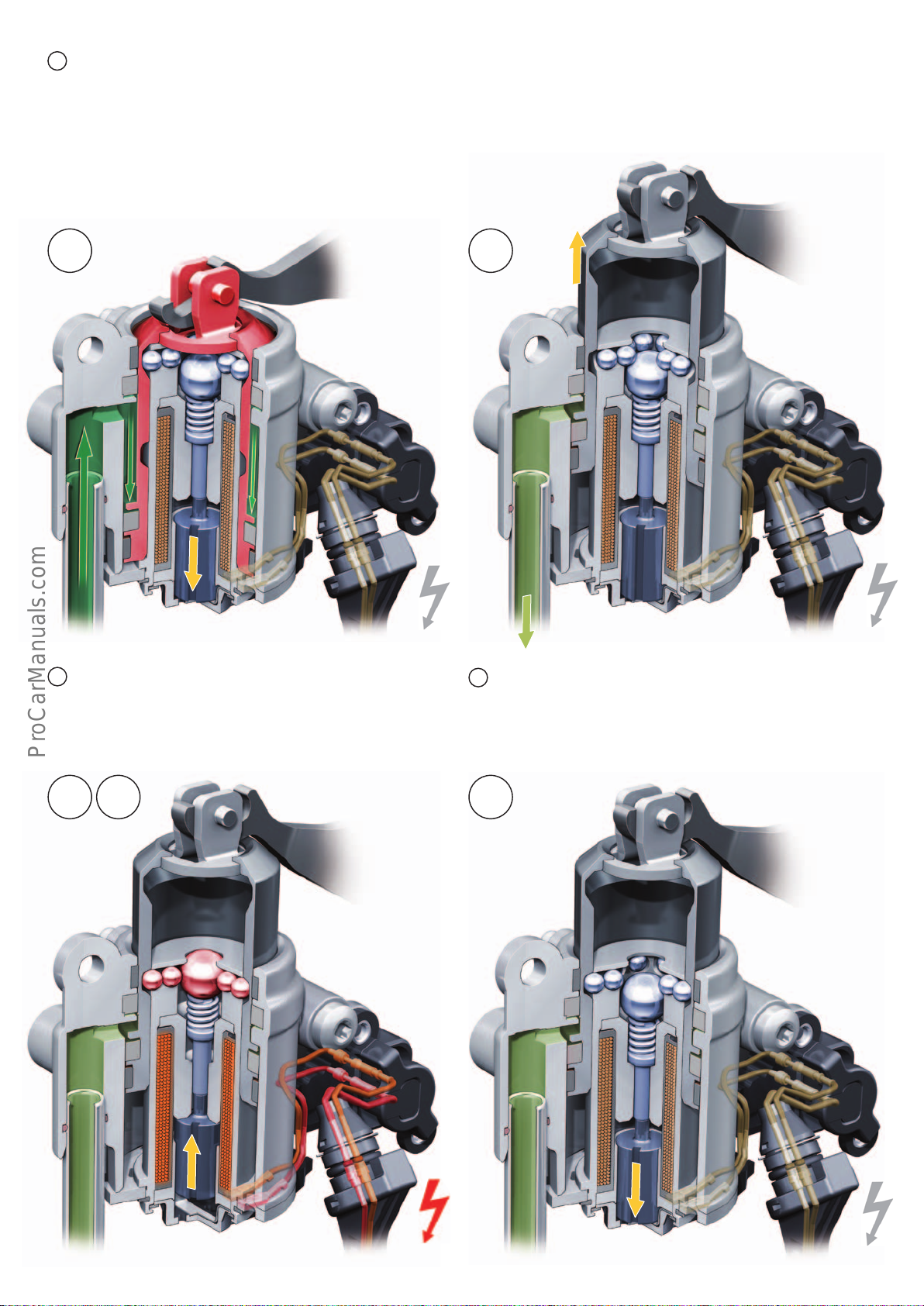
Engage parking lock (P-ON --> P-OFF)
< Back
Forward >
Ξ Contents
4
Starting scenario
Taking (2B) as a starting point – refer to Fig. 644_089 – the engine
is shut o when the vehicle is stationary and the parking lock is
engaged by the Auto-P function. The process of "engaging the
parking lock" (up to (1) on page 53) involves several steps (4A) –
(4E).
4A
4A
To engage the parking lock, the parking lock holding magnet
must first be switched o to allow movement of the selector
shaft.
644_091
4B
4B
Solenoid valve 6N93 is deactivated, whereupon it opens the
inlet from parking lock cylinder to the oil sump. The pressure
in the parking lock cylinder is dissipated. The parking lock is
engaged (P-ON) by the parking lock spring.
644_092
4C
4D
4E
52
644_093
644_094
Page 53
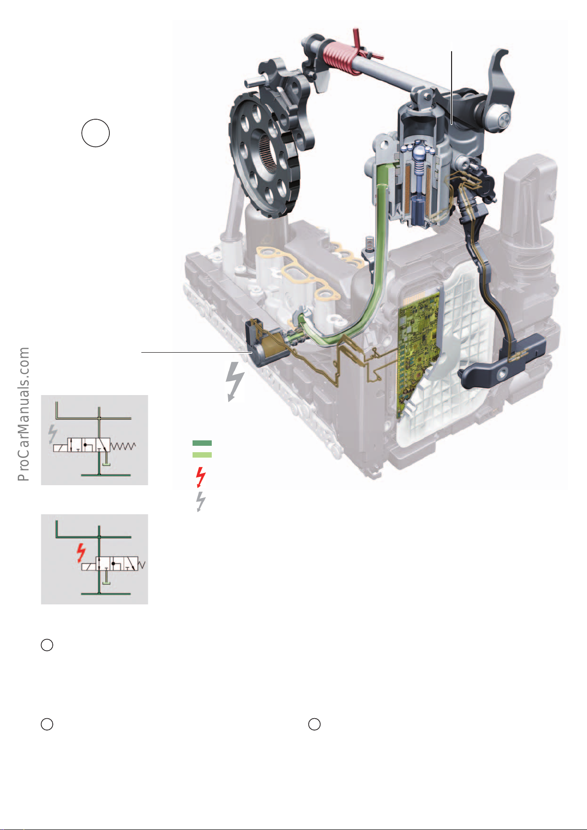
Parking lock engaged (P-ON)
< Back
Forward >
Ξ Contents
1
Gear sensor
G676
Solenoid valve 6 – N93
VSS valve accumulator points
Solenoid valve 6N93 – de-energised
3
Solenoid valve 6N93 – energised
3
4
5
6
1
4
1
2
644_096
5
6
2
644_097
Key:
System pressure
Depressurised
Energised
De-energised
1 System pressure from pressure
accumulator
2 To gear actuator control unit
3 To parking lock cylinder
4 To clutch control unit
5 To clutch control unit
6 To oil sump
644_076
Solenoid valve 6N93
Solenoid valve 6N93 has two adjacent switch positions.
• Energised switches the system pressure to the
parking lock cylinder.
• De-energised opens the inlet from the parking
lock cylinder to the oil sump.
4C
If the P-ON positon is detected by the gear sensor G676, the
selector lever sensors control unit J587 energises the parking
lock solenoid N486. The P-ON position is engaged thereby
ensuring that the parking lock cannot be disengaged due to a
malfunction.
The pressure in the pressure accumulator is now actively
4D 4E
reduced by alternately activating the gear actuators. After the
pressure has dissipated, the gearbox control unit J217 cuts
out unless prevented from doing so by other or internal
activity. The control unit J587 remains active and energises
the parking lock solenoid N486.
N486 is energised by J587 until the gateway initiates bus idle
mode, whereupon J587 cuts out. The parking lock is now in
the starting position (1) – refer to page 48 or Fig. 644_095.
53
Page 54
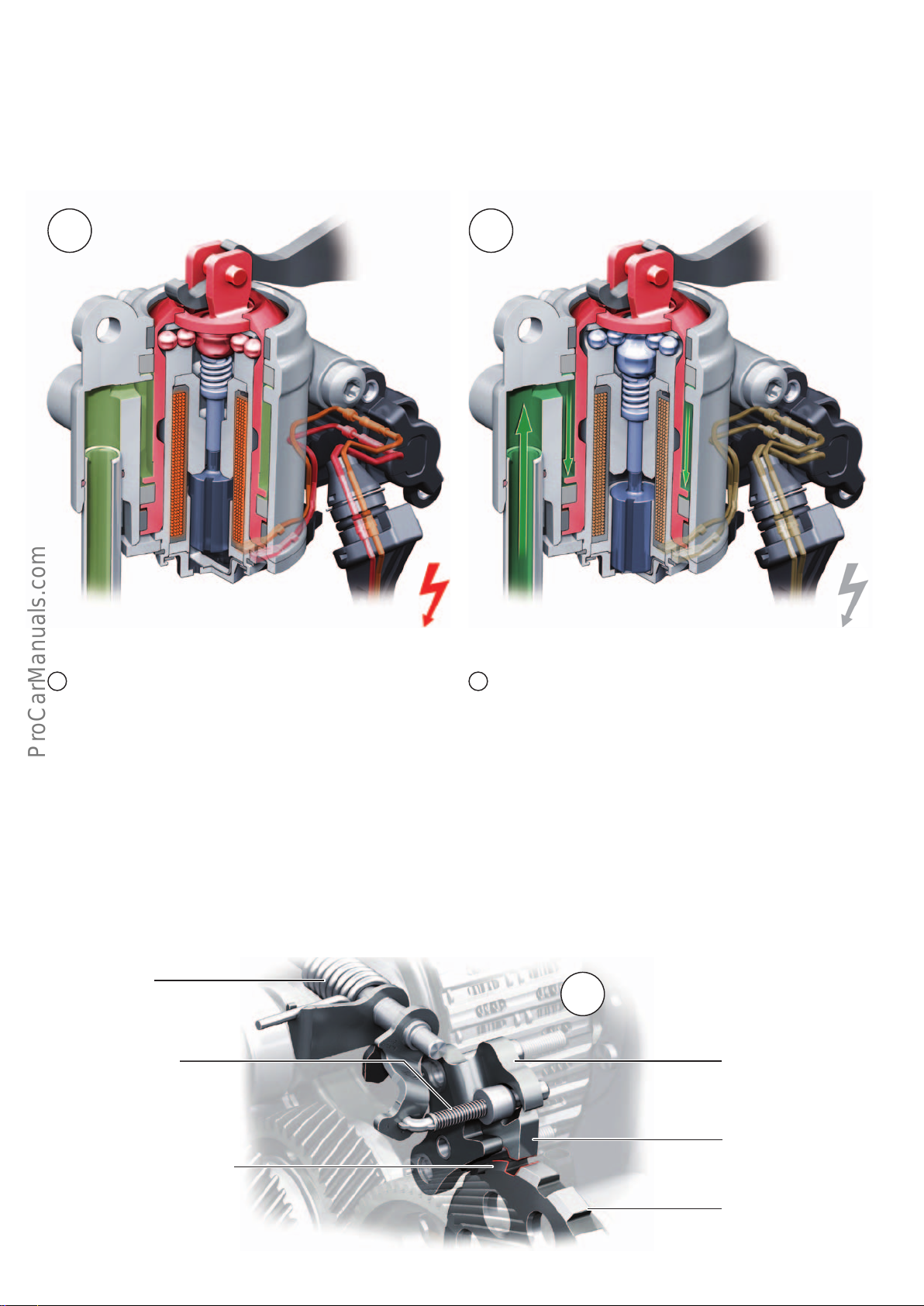
Functional reliability of the parking lock
< Back
Forward >
Ξ Contents
The system is configured such that the P-OFF position is maintained in two ways when the system is fault-free: first, hydraulically by means of system pressure; and, second, electro-mechanically by means of the locking mechanism operated by the parking
lock solenoid N486.
X
If the system malfunctions during vehicle operation, this ensures
that the parking lock is not engaged after a simple fault.
Y
644_098
In the event of an unwanted drop in pressure in the
X Y
mechatronic unit, the P-OFF position is maintained by the
parking lock magnet N486. Given that N486 is activated by
the selector lever sensors control unit J587 (selector mechanism), the P-OFF position is maintained even if there is a loss
of power to the mechatronic unit.
Parking lock mechanism
The parking lock mechanism is a carry-over from the previous
gearbox and adopts the functional principle used by many gearboxes.
Parking lock spring
Sliding cone with spring
644_099
In the event of a fault in the power supply to N486 from the
selector lever sensors control unit J587, the P-OFF position is
maintained electrohydraulically by the mechatronic unit.
P-OFF position
1
Thrust bearing, fixed
If the parking lock gear is as shown
here, the locking pawl can lock into
the tooth without encountering any
resistance.
54
Pawl with spring
Parking lock gear
644_100
Page 55
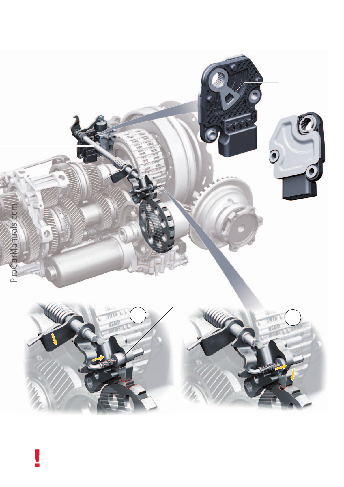
Gear sensor G676
< Back
Forward >
Ξ Contents
The position of the parking lock is monitored by the gearbox
control unit J217 along with the gear sensor G676.
The G676 in DL382 with shift-by-wire is identical in design to the
sensor of the DL382 with selector lever cable (shift-by-cable). In
the DL382 with shift-by-wire, the sensor signal is used only to
determine the position of the parking lock. The name of the sensor
has been adopted from the first generation gearbox.
Selector shaft
For further information about the G676, refer to the AudiService TV
programme: "7-speed dual clutch gearbox 0CK – Stronic Part2 –
Service and practical advice for workshop personnel" of 26.10.2014.
Sender element trim
P-ON position – locking pawl not engaged P-ON position –
Taper and spring are prestressed
locking pawl engaged
2
644_101
If the parking lock gear is "tooth to tooth", the sliding cone is
pretensioned and does not push the locking pawl into the tooth
until the vehicle moves a little.
For safety reasons, the geometry of the parking lock gear and the
locking pawl gearing is designed such that the locking pawl cannot
engage at a speed of over approximately 3 kph.
3
644_102
Note
The parking lock gear locks the pinion shaft of the front final drive. If the vehicle is raised on one side at the front, the locking
action is cancelled on the opposite gear because balancing is provided by the front axle dierential.
55
Page 56
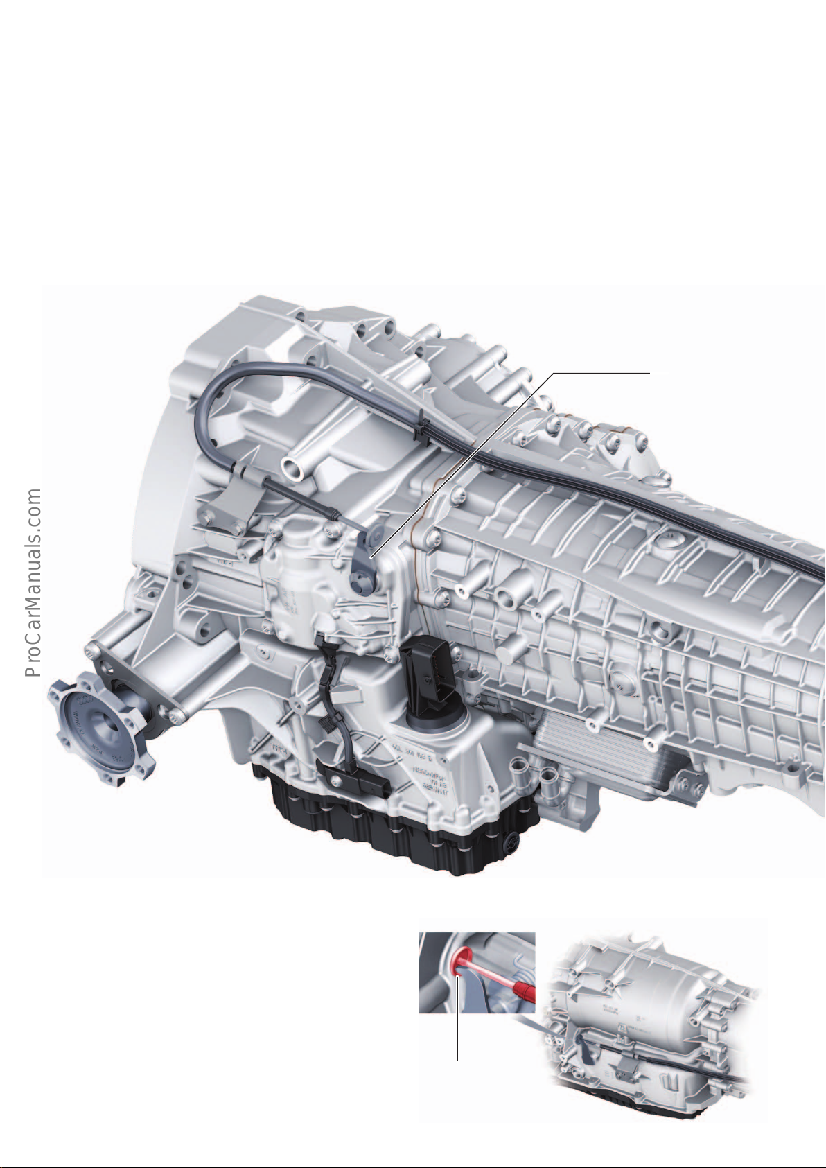
Emergency release of parking lock
< Back
Forward >
Ξ Contents
During normal operation, the parking lock is electrohydraulically
actuated. To allow electrohydraulic disengagement of the parking
lock, the internal combustion engine must be running1) and the
park-by-wire system must have a suitable ATF and power supply.
To hold the parking lock in the OFF position, sucient ATF pressure must be available or the parking lock holding magnet must
have sucient power.
In the event of malfunction, the emergency release mechanism
serves to disengage the parking lock or to hold the P-OFF position
for longer, if necessary.
The emergency release mechanism of the parking lock must be
actuated in the following situations:
• To tow the vehicle
• If the parking lock cannot be released electro-hydraulically due
to a malfunction.
• If the vehicle cannot be manoeuvred or moved due to low
onboard voltage.
• If the internal combustion engine is not running and it is
necessary to manoeuvre or move the vehicle, e.g. in the workshop1).
• For function testing after carrying out assembly work on components of the emergency release mechanism.
Gear shift lever for
parking lock emergency release
Reduction of structure-borne noise transmission
A special feature is the positioning of the emergency release
Bowden cable in relation to the gear selector lever. A rigid rod and
a mushroom-shaped plate are attached to end of the emergency
release Bowden cable and contactlessly envelop the gear selector
lever. This minimises structure-borne noise transmission from the
gearbox to the Bowden cable, and thus into the occupant cell. The
plate and the gear selector lever do not make contact until the
emergency release mechanism is actuated.
Attachment of the
emergency release cable
to the 0D5 gearbox
644_079
56
Page 57
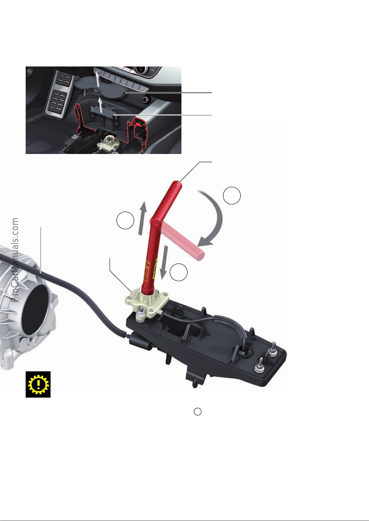
Installation location of the emergency release mechanism
< Back
Forward >
Ξ Contents
Emergency-releasing the parking lock (P-OFF position)
In the AudiA4 (type8W), the parking lock is emergency-released
from inside the vehicle by means of a cable pull. The emergency
release mechanism is located under the cupholder in the centre
console.
644_080
Warning! Before actuating the emergency release mechanism of
the parking lock, the vehicle must be secured to prevent it from
rolling away.
The socket wrench and the screwdriver are contained in the tool
kit. After removing the rubber inlay, remove the cover using a
screwdriver – refer to Fig. 644_080. Items (1) and (2) show the
procedure.
Rubber inlay
Cover
Socket wrench
Turn the socket wrench clockwise
2
as far as it will go and then push it down.
Emergency release cable
Acuator unit for parking lock
emergency release mechanism
3
When the parking lock emergency release mechanism
is actuated, the yellow gearbox warning lamp and the
gear drive position indicatorN light up in the instrument cluster. The following message is also displayed
in the instrument cluster: „Vehicle may roll away!
Pcannot be selected. Please apply parking brake."
1)
In the case of the 0D5 gearbox (AL552), the parking lock can only
be disengaged (P-OFF) when the internal combustion engine is
running, because the 0D5 gearbox uses a mechanical-powered
ATF pump which only conveys ATF when the internal combustion
engine is running. In the case of the DL382 gearboxes, the
internal combustion engine does not have to be running in order
to disengage the parking lock (P-OFF) because this gearbox is
supplied with ATF by an electric-powered ATF pump and a pressure accumulator. This means that the ATF supply is not dependent on operation of the internal combustion engine and that the
parking lock can be disengaged when the ignition is on.
1
Insert emergency release socket wrench
into the actuator unit as shown.
644_078
3
Deactivating the emergency release mechanism (P-ONposition)
Hold the socket wrench with both hands and carefully pull it out
– item (3). Use one hand to guide the socket wrench, so as to avoid
damaging other adjacent parts. If the socket wrench is sti, it is
easier to remove if it is turned slightly clockwise.
Note: Do not under any circumstances turn the socket wrench
back (i.e. anticlockwise) as this will damage the actuator unit.
57
Page 58
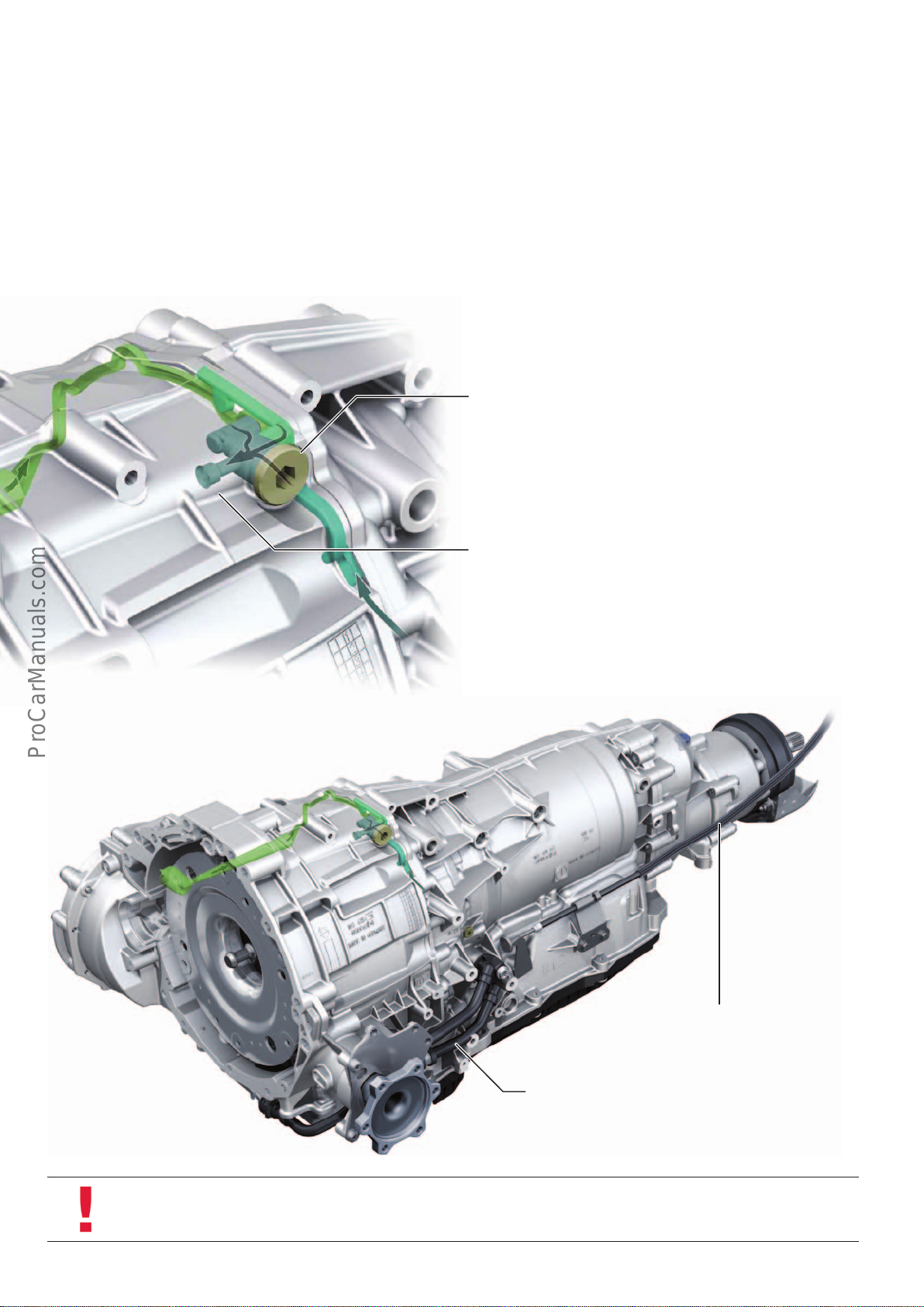
8-speed automatic gearbox 0D5 – tiptronic
< Back
Forward >
Ξ Contents
8-speed automatic gearbox 0D5 is an improved version of 8-speed
automatic gearbox 0BK first used in the Audi A8 (type 4H).
At Audi the 0D5 gearbox has the internal works designation
AL552-8Q. The manufacturer, ZF-GetriebeGmbH, uses the designation 8HP65A. It is rated for an input torque of up to 700Nm
and, in the AudiA4 (type8W), serves to transmit power from the
high-performance engines with a peak torque of 400Nm or higher.
For basic information about 8-speed automatic gearbox 0BK, refer
to Self Study Programme457 "AudiA8’10 Power Transmission".
The main new features of the 0D5 gearbox compared to the 0BK
gearbox are described in Self Study Programme632
"AudiQ7(type4M)".
The main dierence between this gearbox and the 0D5 gearbox in
the AudiQ7(type4M) are explained below.
The vents in the oil chambers of the ATF system and the front final drive
are combined in a collecting chamber. The pressure in both oil systems is
equalised through a port connecting the converter bell to the collecting
chamber.
No vent tube in the gearbox bell.
644_081
One-piece emergency release cable
without quick-release coupling
ATF line to ATF cooler made of plastic in 3.0l V6 TDI
Coolant circuit without gearbox cooling valve
N509
644_082
Note
During transportation and when carrying out work on the removed gearbox, the oil from the front final drive and the ATF may
mix via the common gearbox vent if the gearbox is tilted too far. Follow the instructions given in the Workshop Manual.
58
Page 59
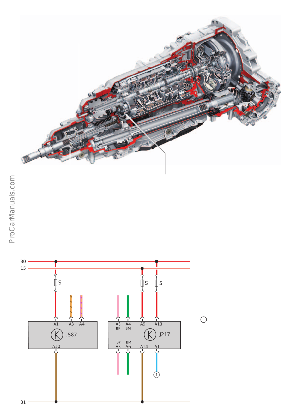
The pressure in the distributor box is equalised by a conventional vent.
< Back
Forward >
Ξ Contents
The 3.0l TDI engine in combination with the
05Dgearbox achieves its top speed in 7th gear.
In 8th gear engine speed is reduced for better fuel
economy. Refer to information on page 62.
The self-locking centre dierential is available in dierent versions (dierent
manufacturers). The characteristics of both versions are identical.
shift-by-wire and park-by-wire
The park-by-wire technology in the 0D5 gearbox is largely identical
to that of the 0BK/0BL gearbox in the AudiA8(type4H). For
further information about the park-by-wire technology, refer to
Self Study Programme457 "AudiA8’10 Power Transmission",
page 48 .
Infotainment CAN
FlexRay
IN
Design of parking lock for passenger car requirements
644_083
In the case of the AudiA4(type8W), information is exchanged
between the selector mechanism and the gearbox via the gateway
by means of the infotainment CAN bus and the FlexRay bus – refer
to pages 42 and 84.
Key:
J217 Automatic gearbox control unit –
gearbox control unit
J587 Selector lever sensors control unit
– selector mechanism
BP FlexRay Bus Plus
BM FlexRay Bus Minus
Starter control signal
1
(P/N signal)
Selector mechanism Gearbox
FlexRay
OUT
644_037
59
Page 60

Gearbox functions
< Back
Forward >
Ξ Contents
Coasting mode
1)
If the applicable conditions are met, the gearbox can activate the
coasting mode. In coasting mode, the engine is disengaged from
the gearbox by opening the power-transmitting clutch. The vehicle
does not enter overrun mode as it usually does, but rather rolls
without any engine braking eect and utilises the kinetic energy of
its motion. Fuel savings can be achieved by adopting an anticipatory driving style.
Activating the coasting mode
The following conditions must be met before the coasting mode
can be activated:
• Audidriveselect mode comfort, auto or eciency
• Coasting mode must be activated in the MMI system –
refer to Eciency assist on the following page.
• Driving positionD, tiptronic
2)
M or eciency modeE
must be selected.
• Vehicle is travelling at a speed of between 55 kph and 160 kph
• Negative accelerator pedal gradient up to 0% accelerator pedal
angle (in drive positionD: Slowly release accelerator pedal. In
eciency mode the accelerator pedal gradient (rate at which
driver releases accelerator pedal) does not have any eect)3).
• Low downhill gradient or low uphill gradient
• Cruise control not active4) – exception: ACC (adaptive cruise
control) with PEA (predictive eciency assist)
–see next item
• Activated by PEA (optional, market-specific) – the PEA utilises
the route data provided by the navigation system. When cruise
control is active, the PEA, in conjunction with the ACC option, is
able to activate and deactivate coasting mode in an anticipatory
and ecient manner depending on the situation.
• The following applies to vehicles with the DL382 gearbox
(Stronic) only:
In coasting mode and in the highest available gear (e.g. in
3rdgear travelling at a correspondingly low speed), coasting
mode can also be activated at low speeds using the Tip+ shift
paddle even if it is no longer activated via the accelerator pedal.
In the case of the Stronic (0CK/0CL), the coasting mode is activated by opening the engaged clutch (K1 or K2). In coasting mode,
the gearbox selects a gear suited to the decreasing speed of the
vehicle. This allows the clutch to close smoothly on restoration of
traction and ensures that the right gear is preselected.
In the case of the tiptronic gearbox (0D5), the coasting mode is
activated by opening the clutch D. For further information about
the function, refer to Self Study Programme632
"AudiQ7(type4M)", page 51.
Deactivating the coasting mode
Coasting mode is deactivated if one of the following controls is
operated:
• Accelerator
• Brake pedal
• Tip- shift paddle
Coasting mode is also cancelled if one of the adjacent operating
5)
conditions is not longer met.
The ACC can deactivate the coasting mode in conjunction with the
PEA.
1)
Coasting mode is not available in all markets due to market-
specific adjustments.
2)
In tiptronicmode, the coasting mode can be activated in the
highest available gear using the Tip+ shift paddle.
3)
The following applies to drive position D: At a slightly greater
negative accelerator pedal gradient up to 0% accelerator pedal
angle (release accelerator pedal slightly more quickly), the
vehicle enters coasting mode.
Notes on the operation of coasting mode
Coasting mode can be activated manually by pulling the Tip+ shift
paddle if the given requirements are met. Example: If the coasting
mode is deactivated by briefly applying the brake, it can be reactivated by pulling the Tip+ shift paddle again.
The Tip- and Tip+ shift paddles can be used to shift at random
between overrun mode and coasting mode within the above
parameters.
60
4)
The cruise control system can be switched o, but the cruise
control system must be activated.
5)
The speed range can vary depending on engine-gearbox combina-
tion. Coasting mode can be activated with the Tip+ shift paddle
even at lower speeds if certain conditions are met.
Page 61
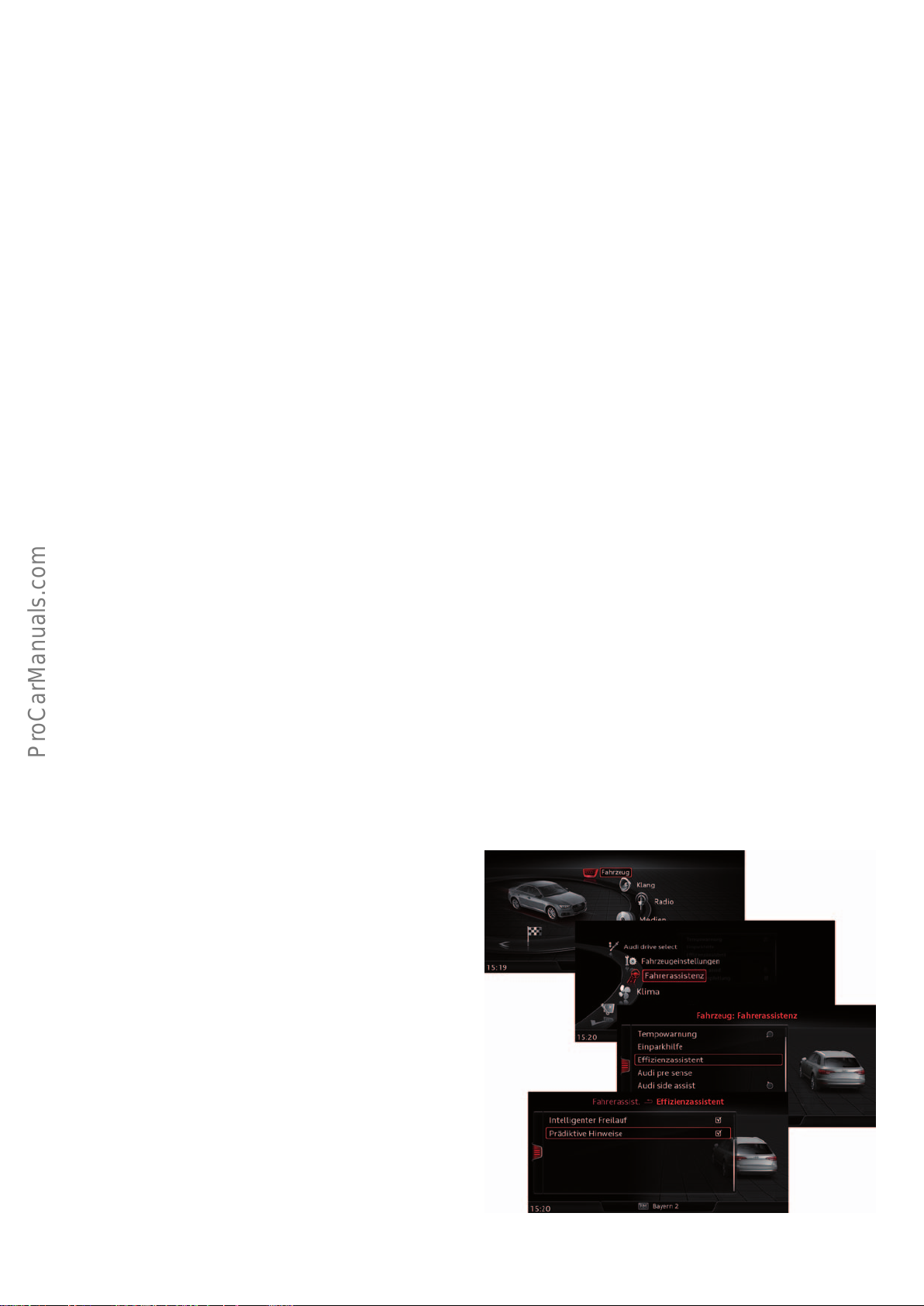
Tip-shifting in D/S
< Back
Forward >
Ξ Contents
Manual gearshifts can be executed at any time using the shift
paddles on the steering wheel (steering wheel tiptronic) in drive
positions D/S. If steering wheel tiptronic is activated, the gearbox
switches to manual mode (tiptronicmode) for a limited time.
If the vehicle is in a normal, constant driving state for a period of
about 8 seconds, the gearbox shifts back into drive position D orS.
The countdown from about 8seconds is stopped in the following
cases:
• Sporty driving style
• Cornering
• Overrun mode
• Selection of another gear with the steering wheel tiptronic
Special features of the steering wheel tiptronic function
• After a long pull of the Tip- shift paddle (long pull-), the
gearbox changes down into the lowest possible gear.
• After a long pull of the Tip+ shift paddle, the gearbox switches
from temporary tiptronic mode to automatic mode.
• If a system malfunction occurs in the selector mechanism, drive
positions P,R,NandD can be selected by simultaneously
pulling both shift paddles, provided that the vehicle is stationary and the brake is applied.
• Coasting mode can be activated with the Tip+ shift paddle if the
given conditions are met. Coasting mode can be cancelled at
any time with the Tip- shift paddle. Coasting mode can be
activated even at low speeds. Coasting mode can be cancelled
at any time with the Tip- shift paddle.
It is possible to return to automatic mode before this in various
ways:
• Pull the selector lever back one position (position B1)
• Move the selector lever into the tiptronic gate and back into the
automatic gate.
• Long pull of the Tip+ shift paddle (long pull+)
In the case of the 0D5 gearbox, the tip shift function can be activated or deactivated in D orS using the adaption function of the
diagnostic tester. For further information about this function, refer
to Self Study Programme632 "AudiQ7(type4M)", page 53.
Launch control program
The Launch Control Program is available in the AudiA4(type8W)
with Stronic (0CK/0CL). The Launch Control Program regulates the
maximum acceleration of the vehicle from a standing start. Refer
to the user manual for operating instructions and other information.
Eciency assist
Eciency assist helps the driver adopt an anticipatory driving style
and save fuel. Refer to Owner's Manual.
The functions "Intelligent coasting" (with automatic gearbox only)
and "Predictive messages" (with navigation system only) are
available in the MMI system under Vehicle > Driver assist > E-
ciency assist.
In vehicles with an automatic gearbox, "Intelligent coasting"
must be selected so that coasting mode is activated.
If the "Predictive messages" is also selected, the "predictive eciency assist (PEA)" function is active. In addition to driver information, PEA influences the activation and deactivation of the coasting
mode – refer to previous page.
1)
1)
Not approved for use in all markets.
644_112
61
Page 62

Audi drive select
< Back
Forward >
Ξ Contents
With Audidriveselect, it is possible to select between dierent
vehicle setups.
In this chapter you will learn how the gearbox control unit
Gearbox setups are tailored to the customer's requirements in a
country-specific manner. For this reason, only typical dierences
between the various modes can be shown here.
responds to the various Audi drive select modes.
Mode Gearbox setup
eciency In eciency mode the gearbox setup follows a defined shift program without driver type recognition. Upshifts
are performed as early as possible and downshifts are performed late in order to save fuel and reduce
emissions. In addition, the engine power output is reduced, allowing the gearbox control unit to reduce
C0
2
the clutch pressure. This, in turn, has a positive eect on fuel consumption and CO2 emissions. In eciency
mode, the coasting mode is activated independently of the accelerator pedal gradient – refer to page 60. In
eciency mode, both the tiptronic functions and drive positionS are available. If drive position S is activated
before shutting o the engine, the eciency mode(E) is automatically activated when the engine is subsequently started1). An E is displayed as the drive position (E1–7or 8) in the gear selection indicator.
comfort The gearbox setup is especially comfort-oriented with soft gear shifts and low engine speeds. As is the case in
auto mode, gear selections are made with the aid of the driver type recognition feature.
auto Driver type recognition in drive positions D and S: In drive positions D and S a driver type recognition is made
on the basis of the driver's driving style. Criteria for driver type recognition include the mode of actuation of
the brake and accelerator, the speed of the vehicle as well as transverse and longitudinal acceleration within
defined periods. Accordingly, an economical driving style leads to early upshifts and late downshifts. A sporty
driving style leads to late upshifts and early downshifts. The driving phases in which the driver adopts an ecient, economical, sporty or manual driving style can be read out using the diagnostic tester.
Selector position D: Gearshifts are comfort-oriented and shift point selection is adapted to the driver's driving
style with the aid of driver type recognition.
Selector positionS
1)
: In Sport mode (sport program), the shift points are sporty and adapted to the performance range of the engine. The shift points are configured with the aid of driver type recognition. Shift times
and shift points vary from driving in the standard sport program to a handling course setup with short, noticeable shift cycles.
dynamic If dynamic mode is selected, the gearbox control unit activates the sport program (drive position S).
In dynamic mode, both the tiptronicfunctions and drive position D are available. If selector position D is activated before shutting o the engine, selector position (D) is again activated when the engine is subsequently
1)
started
. If the driver wishes to have selector position S, he must select this.
individual In individual mode, the driver can freely select the gearbox setup irrespective of other vehicle systems.
1)
Based on the emission class, the drive programs of selector position D or E are always preselected when the vehicle is restarted.
Note
In the case of certain engine-gearbox combinations, maximum speed is only achieved in the auto and dynamic modes.
Reference
For further information about Audidriveselect, refer to Self Study Programme646 "AudiA4 (type8W) Vehicle Electrics and
Electronics".
62
Page 63
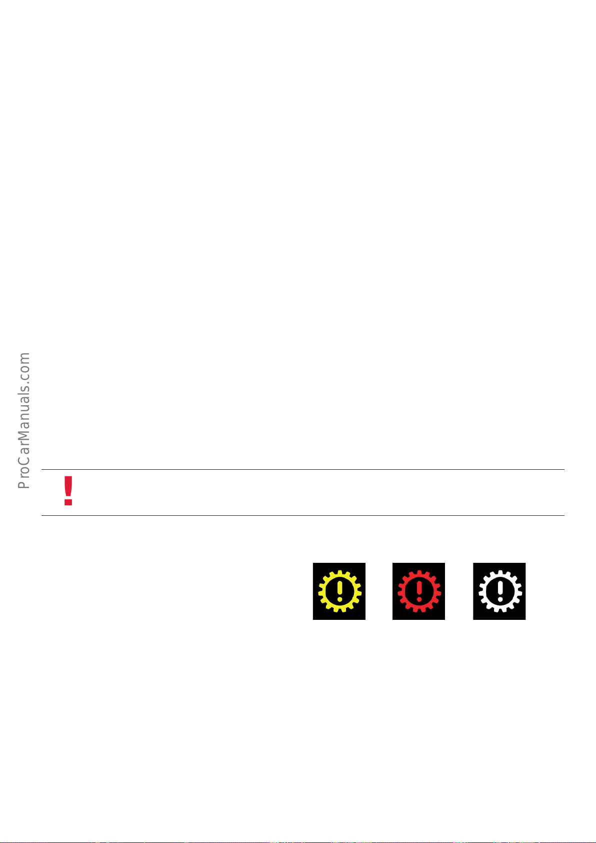
Navigation-data-based gear selection
< Back
Forward >
Ξ Contents
Provided that suitable data is available from the navigation system
(optional and market dependent), the automatic gearbox utilises
relevant route data for gear selection purposes. The gearbox
control unit processes information on the route ahead, e.g. curvature of corners or corner length. The gearbox control unit also
detremines whether the vehicle is driving in or outside built-up
areas.
Towing vehicles with a manual gearbox
If a vehicle with an automatic gearbox needs towing, the usual
restrictions on automatic gearboxes apply:
• Actuate the parking lock's emergency release mechanism
• Max. towing speed 50kph
• Max. towing distance 50 km
To tow the vehicle with the axle raised, the instructions in the
Owner's Manual must be followed.
This information reduces shift frequency and makes it easier for
the gearbox control unit to select or preselect the correct gear. For
detailed information about this function, refer to Self Study
Programme 457 "AudiA8’10 Power Transmission", page 58 .
Navigation-data-based gear selection can be activated or deactivated by selective adaption using the diagnostic tester. Refer to
Self Study Programme 632 "Audi Q7 (type 4M)", page 53 .
Reason
When the engine is at standstill, the oil pump is not driven and
certain parts of the gearbox are not lubricated.
In the dual-clutch gearboxes, overspeeding occurs when a vehicle
speed of 50 kph is exceeded, depending on which gears are
engaged in the sub-gearboxes.
Failure to observe the towing conditions can lead to serious
gearbox damage.
For more detailed information, refer to Self Study Programme386
"6-speed dual-clutch gearbox 02E (Stronic)", page 86.
Gearbox warning lamps and driver information
The gearbox control unit provides a large number of notes and
fault messages, which can be displayed to the driver in the instrument cluster according to their priority. For further information,
please refer to the Owner's Manual.
Note
Refer to the further information on towing given in the Owner's Manual.
63
Page 64
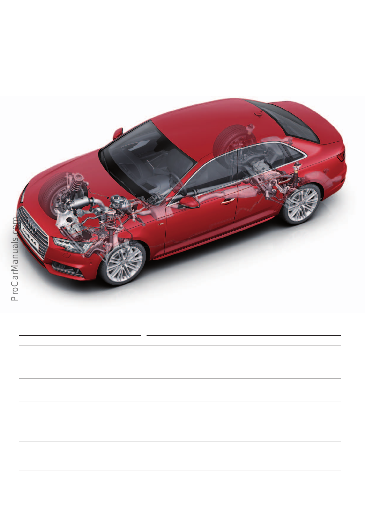
Chassis
< Back
Forward >
Ξ Contents
Overall concept
The chassis of the AudiA4 (type8W) a new development compared to the chassis of the preceding model. As the second Audi
model after the AudiQ7(type4M), the A4 is based on the new
modular longitudinal platform (MLBevo).
A key development goal was to achieve systematic lightweight
construction while resolving the conflict of objectives between
high ride comfort and outstanding driving dynamics.
The following suspension variants are available for the Audi A4 (type 8W).
Suspension variants Features
Standard suspension (1BA)
Sports suspension (1BE)
Heavy duty suspension (1BR)
Heavy duty suspension (1BB)
1)
1)
1)
1)
Sports suspension with electronic
damper control (1BQ)
1)
Suspension with electronic damper
control (1BL)
1)
The standard suspension is standard equipment.
This chassis version is optional. Ride height is approximately 23 mm lower than
that of the standard suspension. The distinctly sporty suspension setup is
achieved by using suitable springs, dampers and anti-roll bars.
Heavy duty suspension 1BR is standard for certain markets and optional in some
markets. Ride height is approximately 13 mm higher than that of the standard
suspension.
Heavy duty suspension 1BB is available for the Chinese market only. Ride height is
identical to that of the standard suspension.
Sports suspension with electronic damper control is also available as an option.
The various damping characteristics are implemented by dierent damper control
maps. Ride height is identical to that of standard suspension 1BE.
The suspension with electronic damper control is an option scheduled to be
launched at a later date. In contrast to sports suspension 1BQ, a comfort-oriented
control stategy is applied. Ride height is approximately 10 mm lower than that of
the standard suspension.
644_119
1)
Production control number
64
Page 65
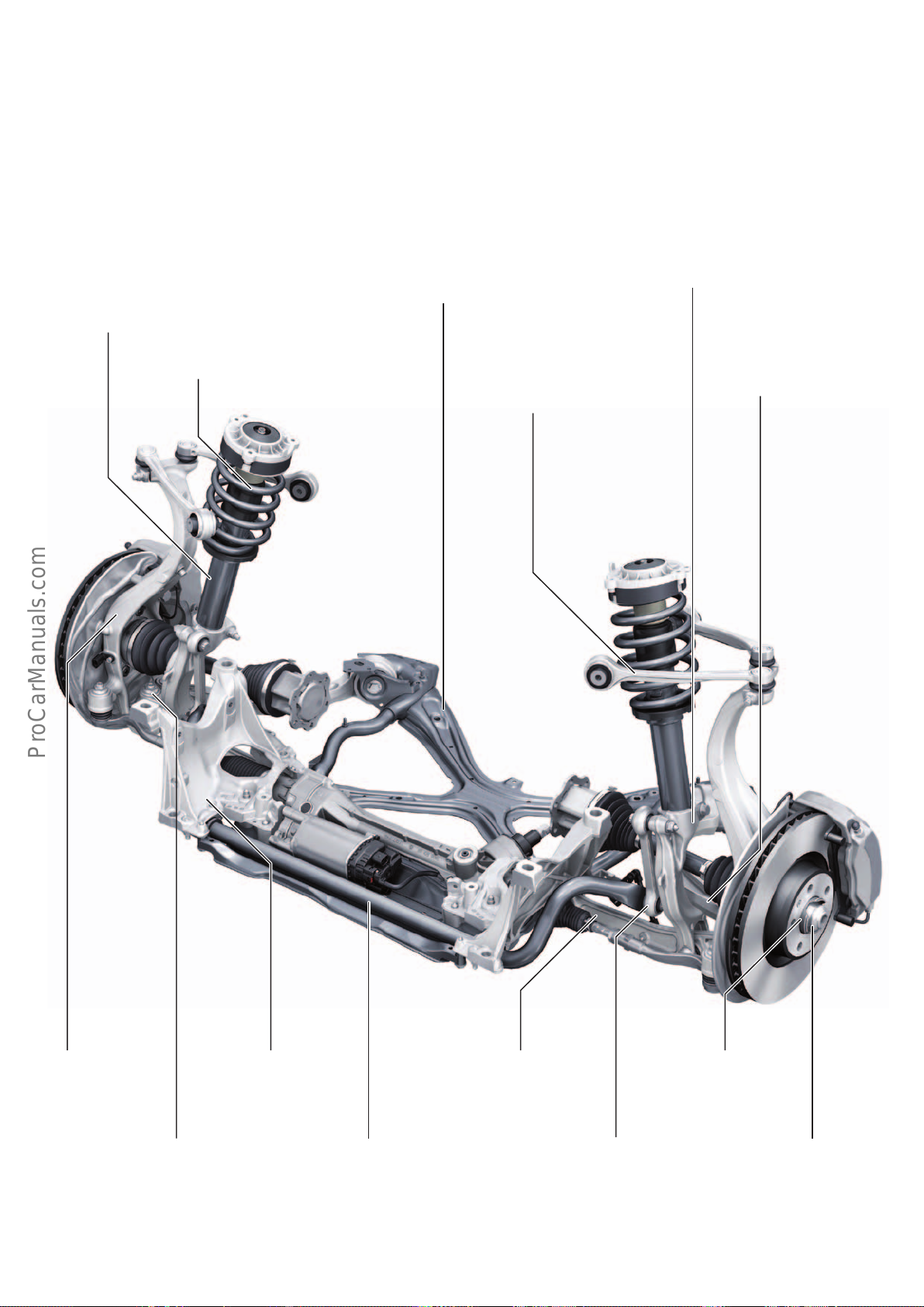
Axles and wheel alignment
< Back
Forward >
Ξ Contents
Front axle
The front axle is based on the Modular Longitudinal Platform
(MLBEvo). The Audi A4 (type 8W) adopts the tried and tested
five-link axle concept already used on other Audi models.
Damper
• Single-tube damper
• Twin-tube damper
• Polyurethane auxiliary spring
• Low-friction axial bearings
for upper strut mountings (new development)
1)
1)
Spring
• Steel springs with linear characteristic
Cross strut
• Steel construction
• bolted to subframe
to increase rigidity
The system components are basically identical in design and
function to those of the front axle on the AudiQ7 (type4M).
Suspension strut knuckle
• Cast aluminium construction
• Bolted to support link
Upper link
• Forged aluminium construction
• Mounted directly to body without
separate bearing pedestal
Guide link
• Forged
aluminium construction
Pivot bearing
• Forged aluminium
construction
Joint
• Spherical joint as connection between
wishbone and pivot bearing
• Aluminium housing
Engine/gearbox mount
• Cast aluminium node
Support link
• Forged aluminium construction
Anti-roll bar
• Tubular anti-roll bars
• Vulcanised bearing elements for 1BB
Wheel bearing
• Second generation
wheel bearing
Tie rod
• Aluminium housing with
rubber-metal bearings
Wheel hub
• Steel construction
1)
Depending on suspension version.
644_120
65
Page 66
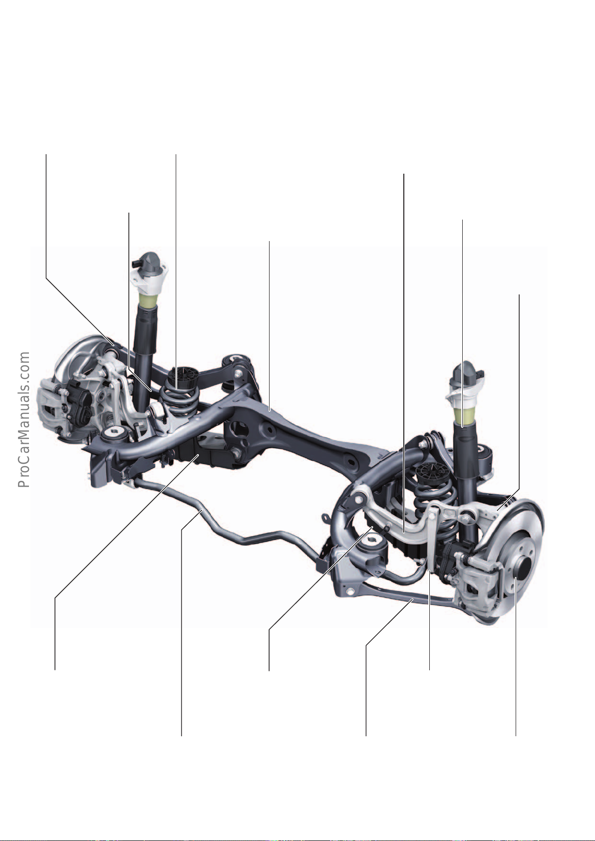
Rear axle
< Back
Forward >
Ξ Contents
The rear axle of the new five-link rear axle is based on the modular
longitudinal platform (MLBevo).
Upper rear wishbone
• Steel construction
Track link
• Steel construction
Spring
• Steel spring with linear spring characteristic
Engine/gearbox mount
• Steel construction
• Flexible body attachment, achieved using rubber-metal
bearings at the rear and hydraulic bearings at the front
• 2 variants for front-wheel drive / quattro drive
The system components are basically identical in design and
function to those of the rear axle on the AudiQ7 (type4M).
Upper front wishbone
• Forged aluminium design
• Attachment of the anti-roll bar coupling rod and
the linkage of the level control system sensor
Damper
• Single-tube damper with
additional polyurethane spring
Wheel carrier
• Aluminium casting
• 2 versions based on dif-
ferent wheel bearings
Aero trim
• Attached to the spring link
at the bottom by clips
• reduces lift and drag coecient
• Stone guard
Spring link
• Shaped aluminium extrusion profile
• Attachment of spring and damper
• Concealed by aero trim in diagram
Anti-roll bar
• Solid anti-roll bar for 1BR,
otherwise tubular anti-roll bars
• 2-piece bearing shells, loose
and bolted using steel clamps
Tie rod
• Aluminium extrusion
profile with rubbermetal bearings
Lower front wishbone
• Steel construction
• Carryover from
AudiQ7 (type4M)
Wheel bearing
• Second generation wheel
bearing
• 2 variants for front-wheel
drive / quattro drive
644_121
66
Page 67
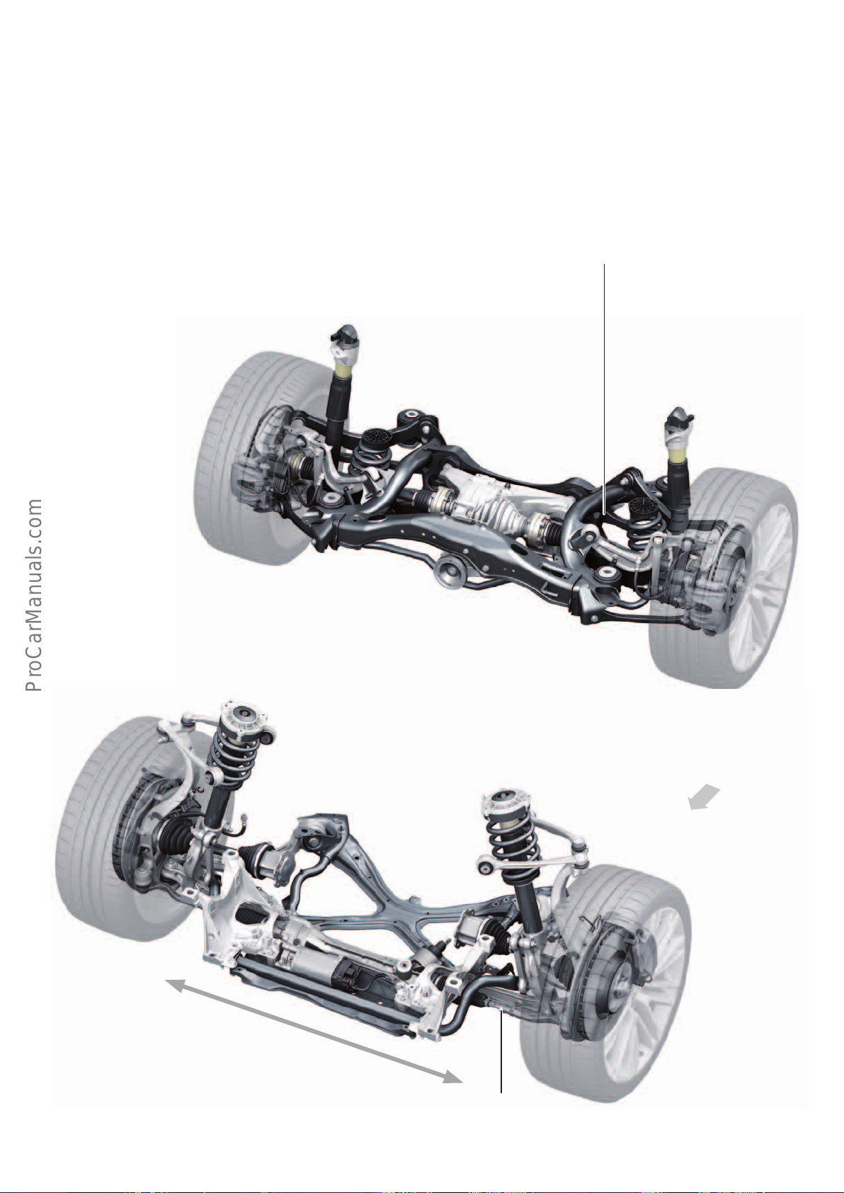
Wheel alignment
< Back
Forward >
Ξ Contents
The left and right tracking values on the front axle can be adjusted
separately by altering the length of the track rods. The camber can
be balanced (centred) within narrow limits by shifting the
Rear axle
Tracking adjustment at attachment point
Spring link subframe
(concealed by aero trim)
subframe transversely. Individual tracking values and individual
camber values can be adjusted on the five-link rear suspension.
Tracking adjustment at attachment point
of track link and subframe
(not shown in graphic)
Front axle
Direction of travel
Camber balancing
Tracking adjustment
644_127
67
Page 68
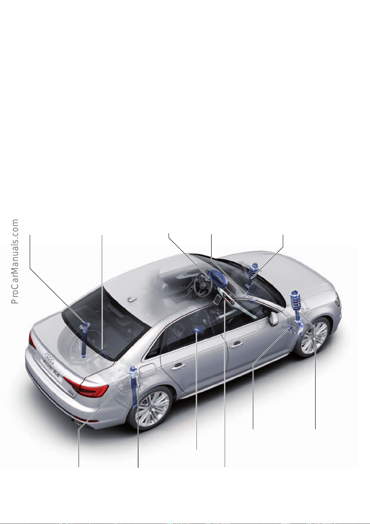
Standard/sports suspension with electronic damper control (1BL/1BQ)
< Back
Forward >
Ξ Contents
The system is based on the electronic damper control system used
in the AudiA4(type8K). A key new feature is the suspension
control unit J775 incorporating the control software. In addition,
the body acceleration sensors previously designated as independent system components are integrated in this control unit together
with the sensors for measuring torque about the x and y axes
(pitching and rolling rates).
CDCivo dampers ("continuously damping control internal evolution") are used. The supplement "internal" in the designation refers
to the integration of the solenoid valve into the damper. The
addition "evolution" refers to the latest technically advanced
damper generation. The control unit activates the solenoid valve by
means of a PWM signal thereby bypassing the piston valves.
Depending on the opening cross-section of the valve, the damping
forces can be varied in the tension and compression stages. Activation is wheel-selective.
Level control system
sensor, rear left
G76
Damper with damping
adjustment valve,
rear left
N338
Control unit
in instrument panel
J285
To be able to determine the required damping forces, the control
software has a modular design. The vertical module evaluates lift,
pitching and rolling movements of the body structure on the basis
of the sensors integrated in the control unit.
The transverse module utilises the measured data from the steering angle sender and the transverse acceleration sensor (in the
airbag control unit) to determine the transverse dynamics.
The longitudinal module assesses the vehicle's longitudinal
dynamics by evaluating the measured data for brake pressure
(from the ESC) und the driver's torque input (from engine control
unit). A higher-level system module serves to respond to the
actions of other systems (ESC, EPB, brake assist etc.).
In addition, the speed of the vehicle and the road conditions
(surface unevenness – determined from the measured data supplied by the body acceleration sensor in control unit J775) are
incorporated into the control process.
Level control system
sensor, front left
G78
Damper damping adjustment
valve, front left
N336
Damper with damping
adjustment valve,
rear right
N339
Level control system
sensor, rear right
G77
Suspension control unit
J775
Button in operating unit 1 for drive
and convenience functions B791
(alternatively, the drive program
can be configured in the MMI)
Level control system
sensor, front right
G289
Damper with damping
adjustment valve,
front right
N337
644_128
68
Page 69
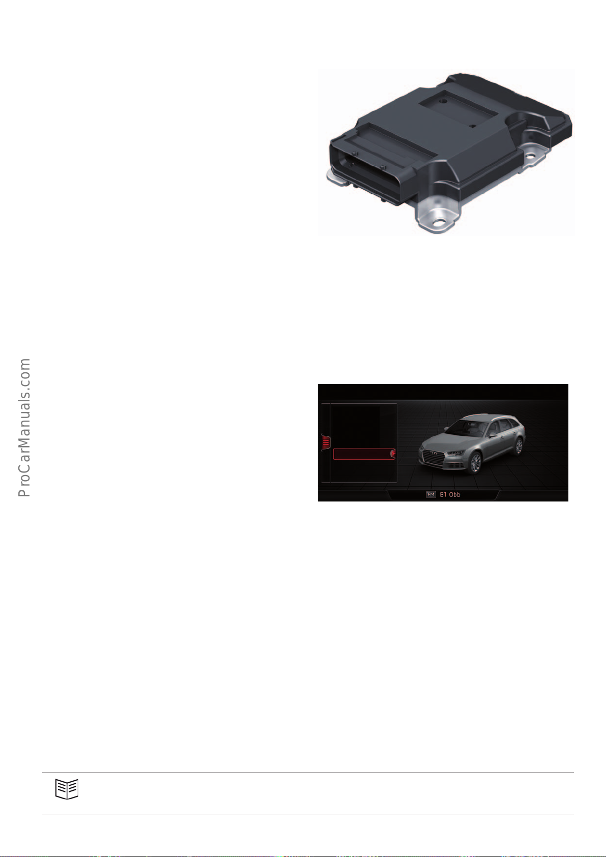
Suspension control unit J775
< Back
Forward >
Ξ Contents
As previously in the AudiQ7 (type4M), the suspension control
unitJ775 is used for damper control in the Audi A4. This function
therefore replaces the adaptive suspension control unit J197.
In addition, the sensors are integrated in the control unit to
measure vertical acceleration (z) as well as the torque about the
longitudinal axis (x direction, rolling movements) and the transverse axis (y direction, pitching movements).
Since the control unit also computes the vehicle's dynamics for the
sport dierential, it is available in two versions. In the case of
vehicles with a sport dierential without damper control, the
control unit does not require the above-mentioned sensors. The
control unit is not used in vehicles without a sport dierential and
without damper control.
The control unit is mounted on the centre tunnel at the front of the
vehicle. It communicates across the FlexRay data bus.
644_129
System behaviour
The electronic damper control system has 3 dierent damping
characteristics. Depending on the setting chosen in
Audidriveselect, the system activates maps which provide a
medium, comfort-oriented or sporty characteristic.
When the ignition is turned on (terminal 15), the damper valves
are activated with short pulses to activate the control system and
vent the valves. If the vehicle is stationary and terminal 15is on,
the damper valves are activated by applying about 400mA (low
damping forces – "soft" characteristic). The highest damping forces
are produced when a current of about 1.9 A is applied.
If it is no longer possible to activate a damper or if there is no
longer any measured data available from a level control system
sensor, the control system is deactivated.
The damper valves are designed in such a way that medium
damping forces (basic damping) are produced in a neutral (nonactivated) state. The vehicle remains dynamically stable despite
the corresponding loss of comfort.
The system shutdown is indicated to the driver by the usual yellow
pictogram (damper icon) and by a text message.
Vehicle: Audi drive select
eciency
comfort
auto
dynamic
individual
12:00
644_130
Reference
For further information about Audidriveselect, refer to Self Study Programme646 "AudiA4 (type8W) Vehicle Electrics and
Electronics".
69
Page 70
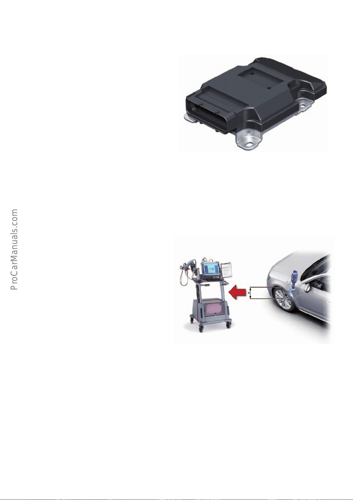
Service operations
< Back
Forward >
Ξ Contents
Control unit J775 is encoded online. The following 3 basic settings
are available for the electronic damper control system:
• Program tension stop
Raise the vehicle on a hydraulic lift such that the wheels lose
ground contact and the dampers can be moved to their tension
stops. The corresponding measured data from the level control
system sensor is stored in the control unit.
• Program zero position of height sensors
This process follows the same approach as the other
Audimodels with adaptive air suspension or damper control
(=programming the default suspension height). The distance
from the centre of the wheel to the wing cutout is measured at
all 4 wheel positions and inidcated to the diagnostic tester. The
control unit stores the corresponding measured data from the
level control system sensor. Together with the data for the
tension stops, the positions of the pistons in the dampers can
be determined using the measured data from the level control
system sensors.
644_129
• Calibrate inertial sensors
This basic setting is used to calibrate the sensors in the control
unit for measuring the pitching and rolling movements as well
as the body acceleration in the z direction.
The basic settings can be recalled separately or collectively. The
activation of the damper valves can be checked by performing an
actuator test.
This check on the dampers is performed on the test bench when
the ignition is o. The dampers are not energised and are tested at
basic damping (medium damping forces).
644_131
70
Page 71
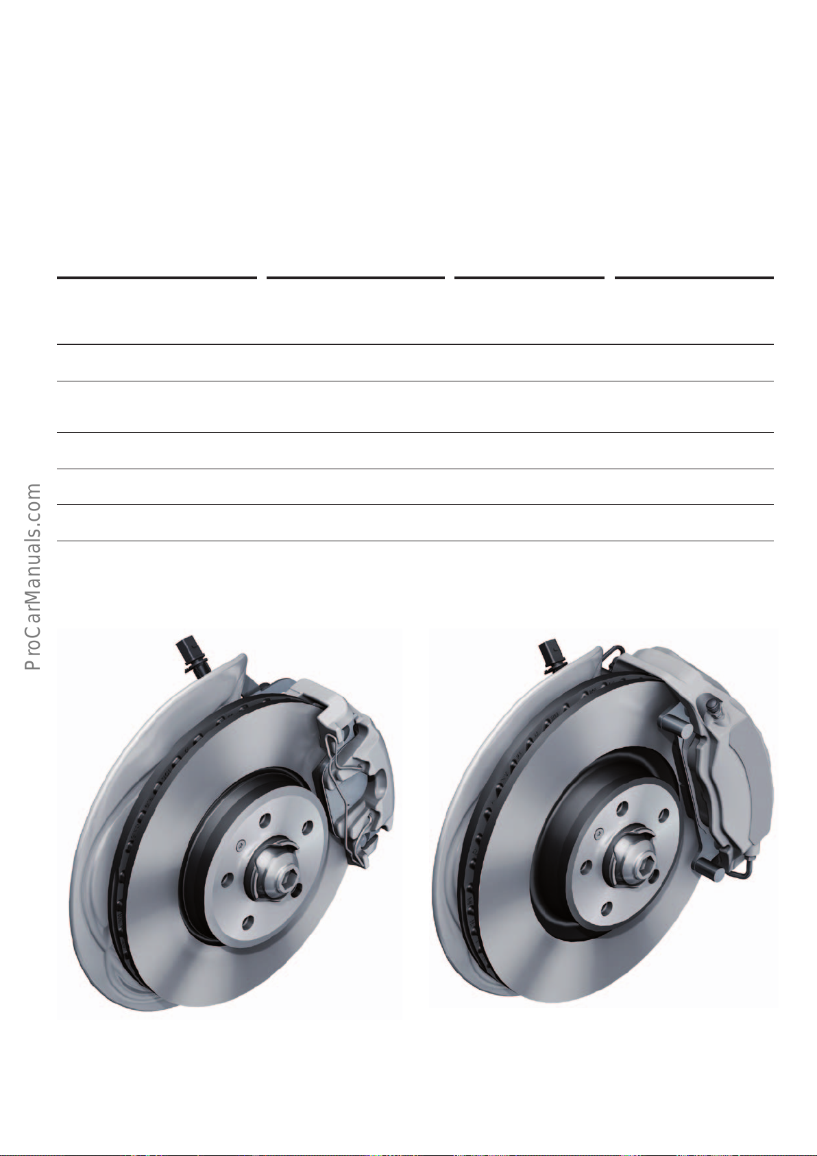
Brake system
< Back
Forward >
Ξ Contents
During the development of the wheel brakes, special attention was
given to lightweight construction. Depending on engine type, a
weight saving of up to 5 kg has been achieved compared with the
previous model. The brake pads are now copper-free and therefore
already meet the mandatory regulations which do not come into
eect until 2021. As is the acse with the previous model, the
electro-mechanical parking brake is standard equipment for the
Audi A4.
The ninth-generation ESC system by RobertBoschGmbH is a
carry-over from the AudiQ7(type4M). The control software has
been adapted for use in the AudiA4. Compared with the previous
model, the brake circuit layout has been modified from diagonal to
a split between the front brakes and rear brakes.
Front axle
Engine type 1.4l TFSI (110 kW)
2.0l TFSI (125, 140 kW)
2.0l TDI (90 – 120 kW)
Minimum wheel size 16“ 16“ 17“
Brake type Conti FN-57
floating caliper
Number of pistons 1 4 4
Brake disc diameter 314mm 318mm 338mm
2.0l TDI (140 kW)
3.0l TDI (160 kW)
Conti 4MF 42-42
fixed caliper
2.0l TFSI (185 kW)
3.0l TDI (200 kW)
Conti 4MF 42-42
Fixed caliper
Brake disc thickness 25mm 30mm 30mm
644_132 644_133
16“ wheel brake Conti FN-57 17“ wheel brake Conti 4MF 42-42
71
Page 72
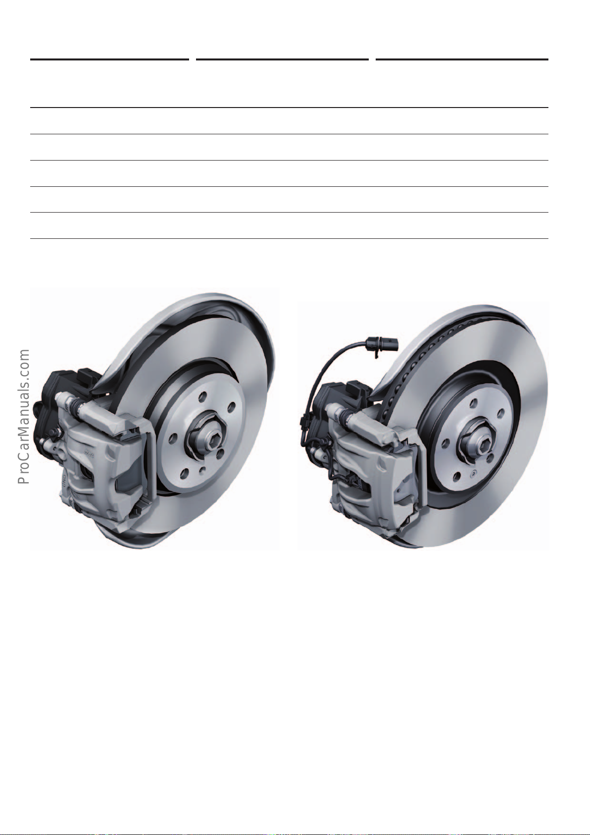
Rear axle
< Back
Forward >
Ξ Contents
Engine type 1.4l TFSI (110 kW)
2.0l TFSI (125, 140 kW)
2.0l TDI (90 – 140 kW)
3.0l TDI (160 kW)
Minimum wheel size 16“ 17“
Brake type TRW PC42 EPBi floating caliper TRW PC43HE EPBi floating caliper
Number of pistons 1 1
Brake disc diameter 300mm 330mm
Brake disc thickness 12mm (solid) 22mm (inside-ventilated)
2.0l TFSI (185 kW)
3.0l TDI (200 kW)
644_134 644_135
16“ wheel brake TRW PC42 EPBi with solid brake disc 17“ wheel brake TRW PC43 HE EPBi with inside-ventilated brake disc
72
Page 73
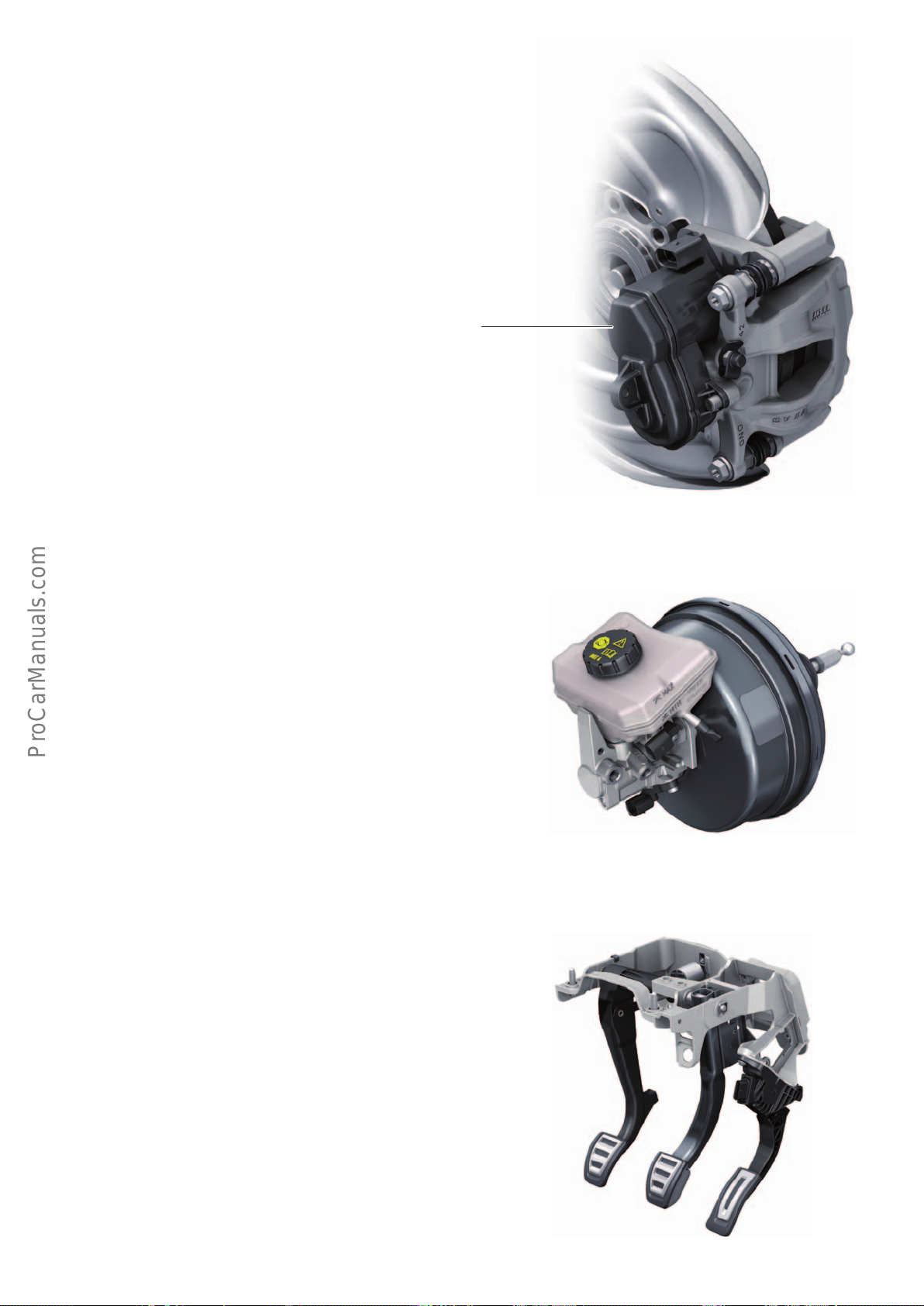
Electro-mechanical parking brake (EPB)
< Back
Forward >
Ξ Contents
Like in the previous model, the electro-mechanical parking brake is
standard equipment for the Audi A4. In terms of design, function,
operation and scope of service, the actuator is identical to that
used in the AudiA7Sportback(type 4G). The control software is an
integral part of the ESC control unit J104. For further information,
refer to Self Study Programme 612 "AudiA3’13 Suspension".
Electro-mechanical parking brake (EPB)
644_136
Brake servo and master brake cylinder
A size 8/9“ tandem brake servo with a "single-rate" characteristic
for left and right hand drive models is used in the Audi A4. The
brake light switch is a carry-over from the AudiQ7(type4M). It is
located on the master brake cylinder and is a Hall-eect sensor.
Vacuum is supplied by a mechanical-powered vacuum pump on the
internal combustion engine.
Models with the 1.4l TFSI engine do not have a mechanical-powered vacuum pump on the internal combustion engine. In this
case, the vacuum in the intake manifold is used.
Foot controls
The pedal assembly is an entirely new development. To improve
acoustics, all pedals are manufactured from enclosed profiles. In
the case of the foot controls, too, special attention was given to
lightweight construction. The aluminium brake pedal is approximately 50% lighter than that of the previous model. A weight
saving of 400 g compared with manual gearbox models was
achieved by using a special bearing pedestal for automatic gearbox
models. The pedals of SLine vehicles feature stainless steel caps,
which are also oered as accessories.
644_137
644_138
73
Page 74
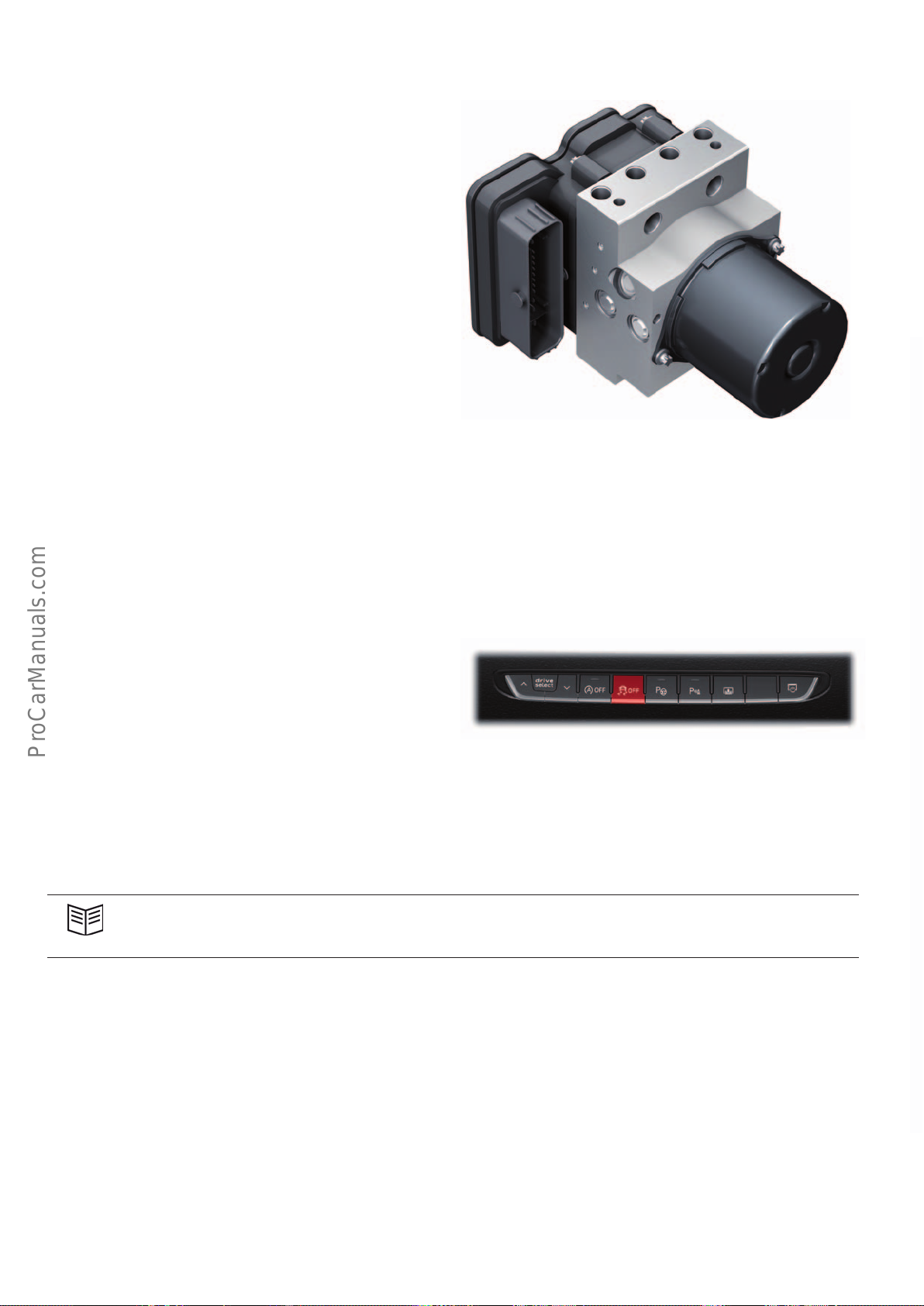
ESC
< Back
Forward >
Ξ Contents
Two versions of the ESC9.0 by Robert Bosch GmbH are used in the
Audi A4. Vehicles equipped with ACC have a higher-performance
version of the 6-piston hydraulic pump and three pressure sensors
for additional measurement of the brake pressure within the brake
circuits. A 2-piston hydraulic pump is used in vehicles without ACC.
These ESC units are already used in the AudiQ7(type4M). The
control software has been modified for use in the A4.
This ESC unit is installed in the engine bay on the left-hand side of
the vehicle (under the engine control unit). The ESC system utilises
the measured data (longitudinal and transverse acceleration, yaw
rate) provided by the sensors in the airbagcontrol unit J234. In
future, they will replace the sensor electronics control unit J849
and the ESP sensor unit J419. The active wheel speed sensors have
also been adopted from AudiQ7 (type4M). The ESC service operations are identical to those for the AudiA7Sportback(type4G) or
Q7 (type 4M).
644_139
Operation and driver information
The 2-stage operating concept has also been implemented in the
AudiA4. Sport mode is activated by briefly pressing the ESC button
(< 3 s). The TCS and ESC control functions are limited in order to
allow a more sporty style of driving. If the ESC button is pressed
for longer than 3 seconds, TCS and ESC are fully deactivated.
Reference
For further information about the design, function and service operations for ESC, please refer to Self Study Programmes480 "AudiA7Sportback Suspension" and 633 "AudiQ7 (type4M) Suspension".
644_124
74
Page 75
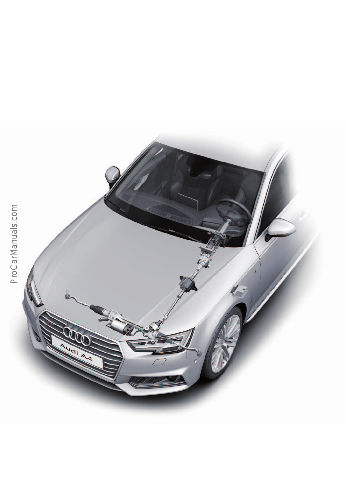
Steering system
< Back
Forward >
Ξ Contents
Overview
Like its predecessor, the AudiA4 is equipped with an electromechanical steering system (EPS). The steering column is mechanically adjustable.
Three-spoke steering wheels are available as standard equipment
and optional equipment. Dynamic steering is also optional.
Steering system with dynamic steering option
644_140
75
Page 76
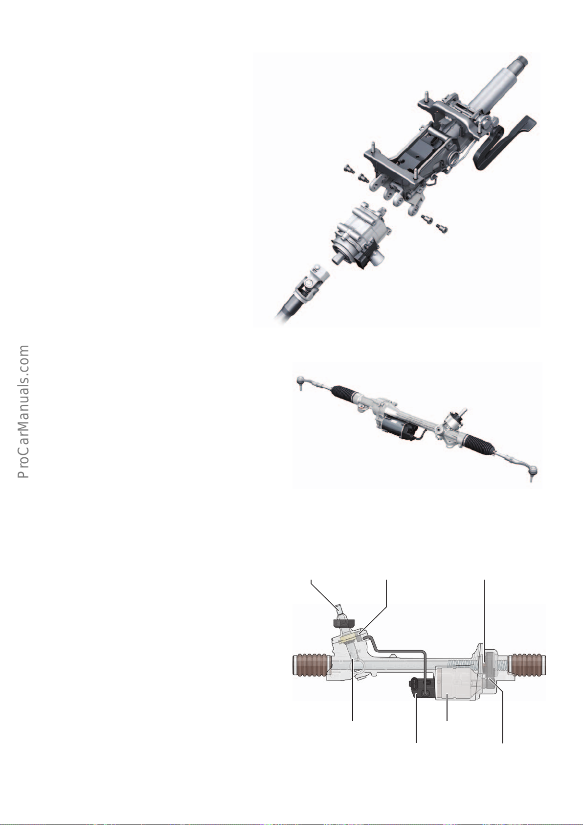
Steering column
< Back
Forward >
Ξ Contents
The mechanically adjustable steering column is identical in design
and function to that of the Audi Q7 (type 4M). The modified installation position and the modified adjustment range (axial/vertical
60/50mm) compared with the Audi Q7 (type 4M) are achieved by
using an adapted bracket and dierent stop elements. If the
vehicle is equipped with the optional dynamic steering system, a
variant with specially adapted connection dimensions is employed.
644_141
Electro-mechanical steering (EPS)
Design and function
The paraxial electromechanical steering system is basically identical
in design to the steering system used in the current VWPassat,
Tiguan and Touran models as well as in the Lamborghini Gallardo.
In contrast to the steering system in the above-mentioned VW
models, the steering angle sender in the Audi A4 is not integrated
in the steering gear, but rather in the steering column switch
module.
Whereas the electro-mechanical steering system in the Audi A3
(type8V) and TT(type FV) models provides steering assistance
through a second steering pinion driven by an electric motor, the
electro-mechanical steering system in the AudiA4 transmits power
to the steering rack through a ball screw as in the Audi R8 (type4S).
Functionally, this steering system is identical to that used in the
Audi A6, A7Sportback(type4G), A8(type4H) and Q7(type4M)
models. The dierence between the Audi A4 and these models is
that the ball nut in the former is driven by a belt drive from an
electric motor aligned in parallel with the steering rack. In the
AudiA6, A7Sportback(type4G), A8(type4H) and Q7(type4M)
models, the electric motor concentrically surrounds the steering
rack.
Torsion bar
644_125
Ball screwSteering torque sender
The paraxial layout was chosen for design space reasons in particular. Whereas the concentric layout involves making allowance for an
installation height of about 120 mm, the installation height for the
paraxial layout is only about 60 mm.
Two versions of the electro-mechanical steering system are
employed in the Audi A4. They have dierent gear ratios. The ratios
for vehicles with dynamic steering are more direct.
76
Steering pinion
Electric motor
All-wheel drive
Belt drive
644_126
Page 77
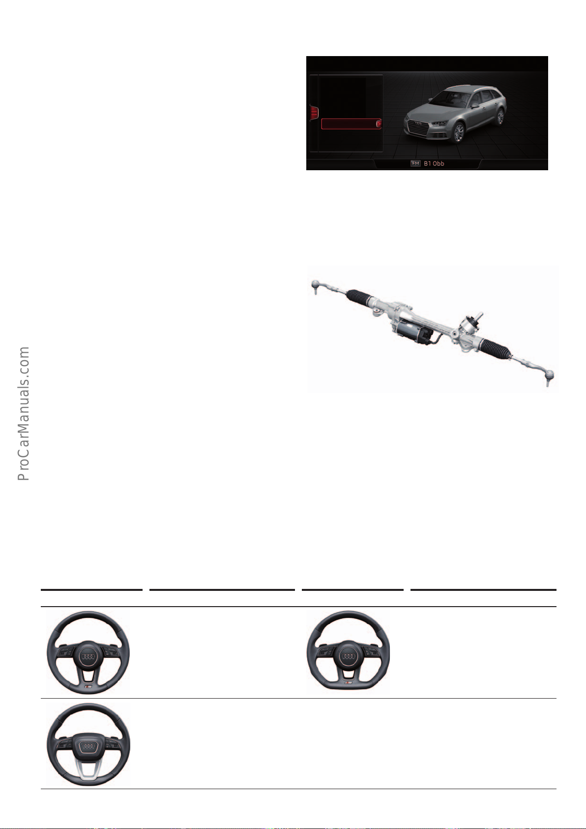
Operation and driver information
< Back
Forward >
Ξ Contents
This steering system is operated by selecting the relevant mode in
the Audidriveselect handling system. Three maps have been
programmed into the control unit for this purpose.
System faults are indicated to the driver by the usual yellow and
red warning symbols. If the maximum steering assistance achievable by the system is less than 60 % of the maximum servo power,
the red warning symbol is activated.
Service operations
The service operations for the steering system used on the Audi A4
are also identical to those for the systems used on the Audi A6,
A7Sportback(type4G), A8(type4H), Q7(type4M) and R8
(type4S) models.
For detailed information, refer to Self Study Programme 612
"AudiA3’13 Suspension".
What is new is that it is no longer necessary to program the
maximum steering stops after replacing the steering. This is
performed automatically and iteratively during subsequent driving
cycles. A basic setting function for resetting the programmed
values allows an existing steering system to be installed in a
dierent vehicle. The steering unit can only be replaced as a
complete unit in service centres. The steering unit in combination
with the subframe is a key factor in body stiness. The instructions
given in the Workshop Manual must therefore be followed when
removing and installing the steering unit.
Vehicle: Audi drive select
eciency
comfort
auto
dynamic
individual
12:00
644_130
644_125
Steering wheels
For the first time, the AudiA4 is based on a worldwide lines
concept with distinctive dierentiating features. A range of threespoke steering wheels are available in the following equipment
lines: base, sport, design, designselection and Sline. Generally,
the steering wheels are distinguished visually by the design of the
airbag module and the steering wheel rim. Two design versions of
the airbag module are used: a round module and a trapezoidal
module.
Steering wheel Equipment Steering wheel Equipment
Steering wheel with round airbag
module
Steering wheel with trapezoidal
airbag module
Steering wheels with a round module are principally used in the
Sline and sport lines. They are oered with and without a flattened rim. Other distinguishing features are options such as
chrome trims, leather trim, heating and tiptronic paddles. In
addition, various switch versions are available.
Steering wheel with round airbag
module and flattened rim
644_145
77
Page 78
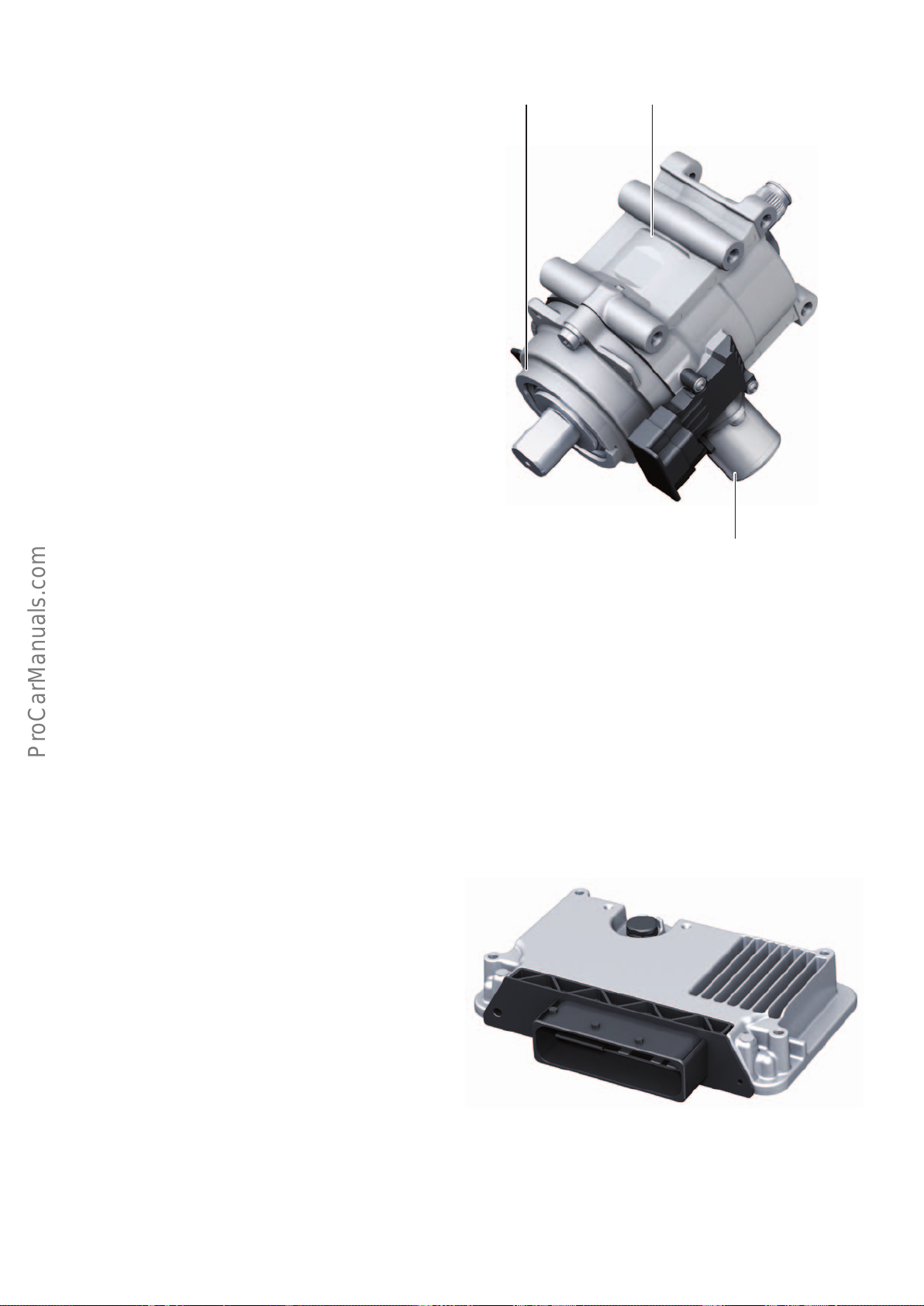
Dynamic steering
< Back
Forward >
Ξ Contents
Dynamic steering is optional for the Audi A4. The AudiA4 is the
first Audi model to be equipped with the second-generation
dynamic steering system. It is identical to the first generation in
general design and function. For further information, refer to Self
Study Programme402"Dynamic Steering in the AudiA4’08".
Other improvements are the numerous detailed modifications
listed below.
New features of the actuator
The gear ratio (angle of rotation of steering pinion relative to angle
of rotation of electric motor) has been changed from 1:50 to 1:30.
This has increased maximum positioning velocity from approximately 450°/s to approximately 650°/s. Maximum engine speed
has also been reduced to 3200rpm from 4500rpm. Acoustic
response and dynamics during stabilising steering inputs have
been improved.
The new, 2-piece housing is about 400 g lighter than that of the
first-generation actuator. Dust and water tightness have been
improved. The gearbox bay and the engine bay are completely
separate.
The mechanical lock for the hollow shaft of the electric motor is a
new design. A proportional magnet is now used instead of the
"digital" electric magnet. A key advantage for the customer is the
elimination of locking noise. Power consumption is reduced.
Electric motorGear unit
Mechanical lock
Dynamic steering actuator
New features of the electric motor
Maximum torque has been increased to 1.4Nm from 1.1 Nm. The
rotor position sensor has double the number of magnetic pole
pairs, increasing the sensor resolution to 7.5° from 15°.
New features of the active steering control unit J792
The control unit communicates across the FlexRay data bus.
Instead of the 3 individual plugs, the electric motor is coupled
electrically by a one-piece connector strip. Use of a dual-core
microprocessor.
Service operations
In terms of the service operations, the second-generation dynamic
steering system is identical to the first-generation system.
If it is necessary to replace the actuator, the overall actuator/
steering column unit must be replaced. If it is necessary to replace
the steering column, the intact actuator can be reused.
644_142
644_143
78
Page 79
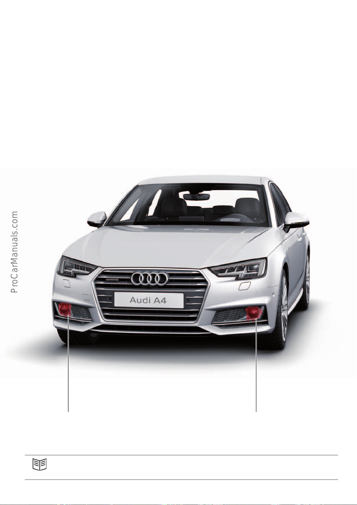
Adaptive Cruise Control (ACC)
< Back
Forward >
Ξ Contents
The fourth-generation ACC system is used in the Audi A4. After the
AudiQ7(type4M), the A4 is the second Audimodel to be equipped
with the latest technology. In terms of design and function as well
as operation and service operations, the ACC system of the A4 is
identical to that of the Q7 (type 4M).
The ACC-based assistance systems first used in the AudiQ7
(type4M) are also oered for the AudiA4. When adapting these
assistance systems for the AudiA4, special attention was given to
eciency and reducing CO
the predictive eciency assist system with ACC and the eciency
mode.
emissions. This applies in particular to
2
The configured time intervals (time gaps) to vehicles ahead can be
varied by the system within certain limits ("flexible time gaps"). In
certain situations it is much more ecient to "coast", i.e. shift the
gearbox into neutral, even when following a vehicle ahead.
Until now, coasting mode could only be activated if ACC had not
detected a vehicle ahead and if an analysis of the navigation data
had shown that the course of the road, speed limits and terrain
topography were suitable for the activation of coasting mode.
ADR sender, right G259 and
ACC control unit J428 (master)
Reference
For detailed information about the system configuration, the assistance functions, system operation, driver information and
service operations for the ACC, refer to Self Study Programme633 "AudiQ7(type4M) Suspension".
644_123
Left ADR sender G258 and
ACC control unit 2 J850 (slave)
79
Page 80
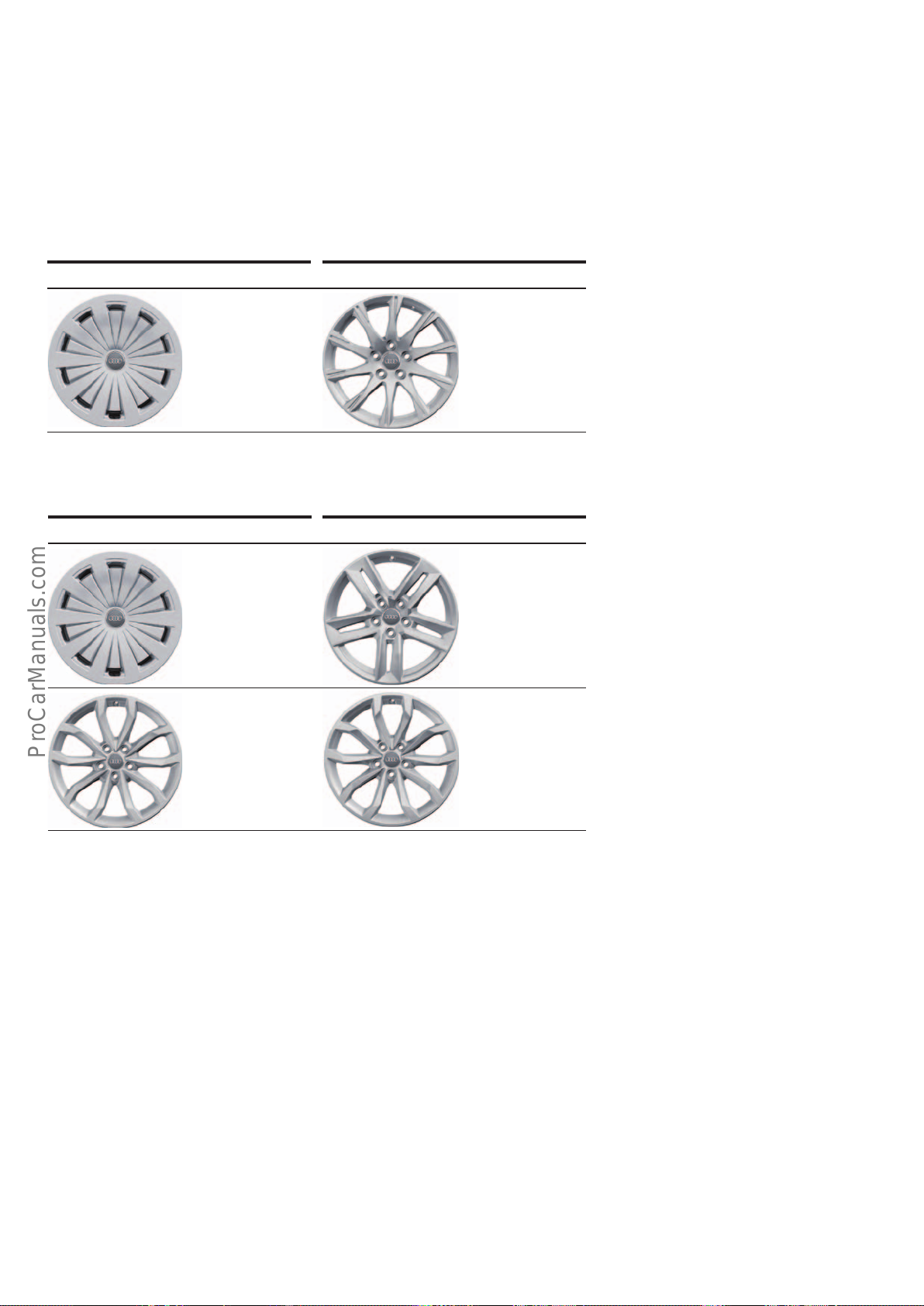
Wheels and tyres
< Back
Forward >
Ξ Contents
Depending on engine type, size 16" and 17" wheels are standard
equipment for the Audi A4 when it is launched. 16"to 18" wheels
are optional. The range of tyres extends from 205/60R16 to
245/40R18.
Standard wheels
7.0Jx16 ET35
Lightweight
forged wheel
205/60 R16
Winter wheels
The "Tire Mobility System" is standard equipment. A space saver
spare wheel is optional. The car comes with a jack if ordered
factory-fitted with winter wheels and if equipped with a space
saver wheel.
7.5J x 17 ET38
Lightweight
forged wheel
225/50 R17
7.0Jx16 ET35
Lightweight
forged wheel
Suitable for snow
chains
205/60 R16
7.5Jx18 ET39
Flow form cast
wheel
Suitable for snow
chains
225/45 R18
7.0Jx17 ET42
Cast wheel
Suitable for snow
chains
225/50 R17
8.0Jx18 ET40
Flow form cast
wheel
245/40R18
644_143
80
Page 81
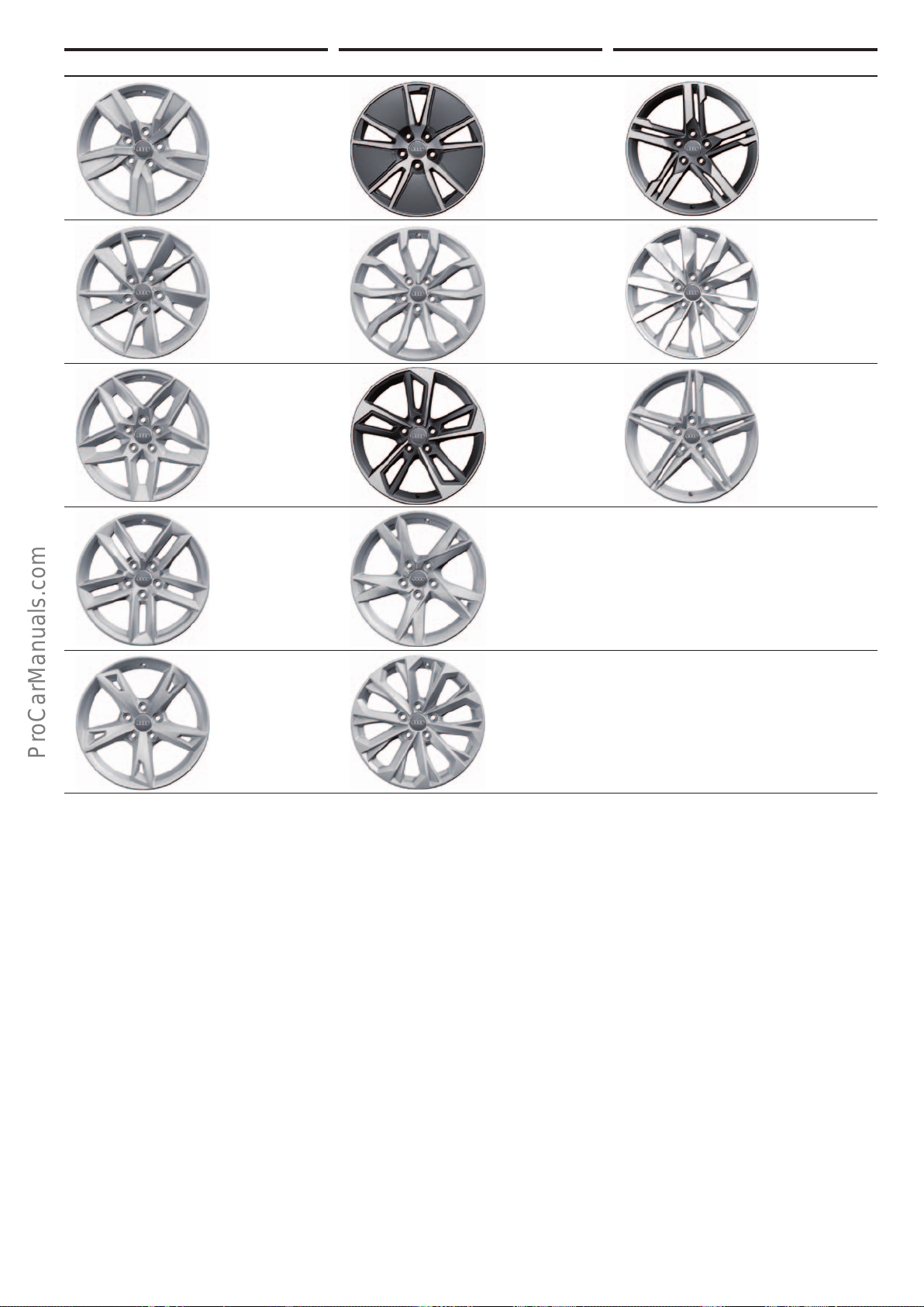
Optional wheels
< Back
Forward >
Ξ Contents
7.0Jx16 ET35
Cast wheel
205/60 R16
7.0Jx16 ET35
Cast wheel
205/60 R16
7.0J x 17 ET38
Cast wheel
225/50 R17
7.5J x 17 ET38
Cast wheel
225/50 R17
7.5J x 17 ET38
Flow form cast
wheel
Bicolor
225/50 R17
8.0Jx18 ET40
Flow form cast
wheel
245/40R18
8.0Jx18 ET40
Flow form cast
wheel
Bicolor
245/40R18
7.5J x 17 ET38
Cast wheel
225/50 R17
8.0Jx18 ET40
Flow form cast
wheel
Bicolor
245/40 R18
8.0Jx18 ET40
Flow form cast
wheel
Bicolor
245/40 R18
8.0Jx18 ET40
Flow form cast
wheel / Sline
245/40 R18
7.5J x 17 ET38
Cast wheel
225/50 R17
Low tyre pressure indicator
The second-generation low tyre pressure indicator (RKA+) is
standard equipment for the Audi A4. In terms of design and
function, operation and driver information as well as service and
diagnosis functions, the system is identical to the systems already
in use in other current Audi vehicles.
7.5J x 17 ET38
Cast wheel
225/50 R17
644_143
81
Page 82
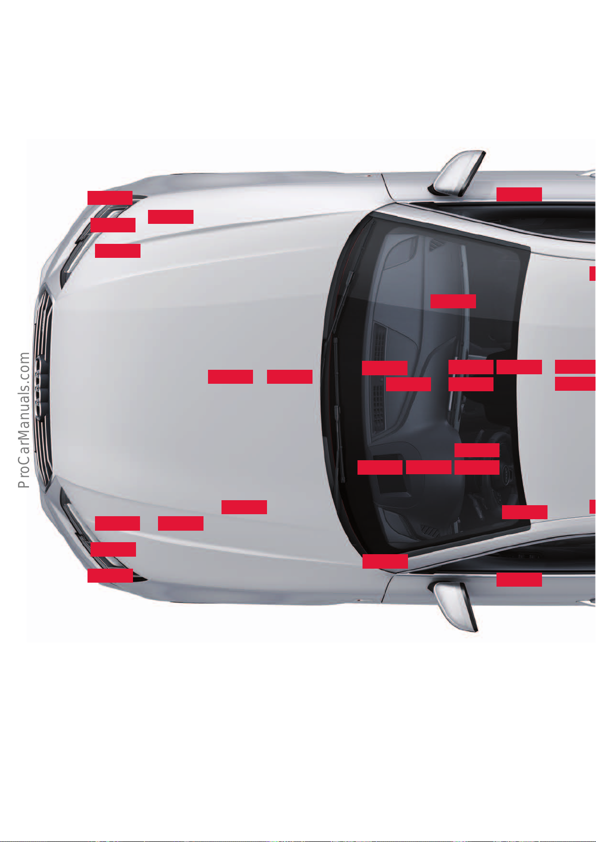
Electrical system
< Back
Forward >
Ξ Contents
Installation locations of control units
Some of the control units shown in the overview are optional and/
or country-specific equipment. For reasons of clarity, not all
control units fitted in the vehicle can be shown here.
J428
J364
J1023
A27
Refer to the current service literature for details of control unit
installation positions as well as instructions for installation and
removal.
J794
J217J500
J685
E87
J844
R242
J387
E380
J245
J587
J623
A31 J104
J1018
J850
Key:
A27 Right LED headlight power module 1
A31 Left LED headlight power module 1
E87 Front air conditioner/Climatronic operating and display unit
E265 Rear air conditioner/Climatronic operating and display unit
E380 Multimedia system operating unit
J104 ABS control unit
J136 Seat and steering column adjustment control unit with
memory
J217 Automatic gearbox control unit
J234 Airbag control unit
J245 Sliding sunroof control unit
J285 Instrument panel control unit
J764
J898
J519
J285
J527
J792
J386
J345 Trailer detector control unit
J364 Auxiliary heating control unit
J386 Door control unit, driver side
J387 Door control unit, pass. side
J393 Central control unit for comfort/convenience system
J428 ACC control unit
J492 Four-wheel drive control unit
J500 Power steering control unit
J519 Electrical system control unit
J521 Control unit for pass. seat adjustment with memory func-
tion
J525 Digital sound package control unit
J527 Steering column electronics control unit
J533 Data bus diagnostic interface
82
Page 83
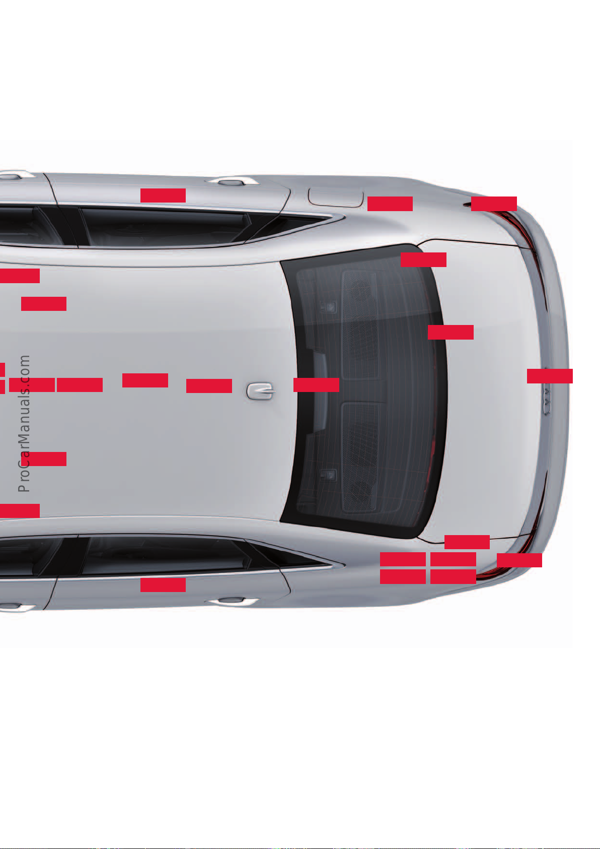
J649
< Back
Forward >
Ξ Contents
J521
J927
R78
J769
J880
J492
J234
J136
J775
J648
J587 Selector lever sensors control unit
J605 Rear hatch control unit
J608 Control unit for special vehicles
J623 Engine control unit
J648 Control unit for rear left information display and
operating unit
J649 Control unit for rear right information display and
operating unit
J685 MMI display
J764 Electrical steering column lock control unit
J769 Audi lane assist control unit
J770 Audi lane assist control unit 2
J772 Rear-view camera system control unit
J775 Suspension control unit
E265
J926
J533
J605
J393
J525
J928
J608
J345
J770
J792 Control unit for active steering
J794 Information electronics control unit 1
J844 Main beam assist control unit
J850 ACC control unit 2
J880 Reducing agent metering system control unit
J898 Control unit for windscreen projection (head-up display)
J926 Door control unit, rear driver side
J927 Door control unit, rear pass. side
J928 Surround camera control unit
J1018 Control unit for light control, left
J1018 Control unit for light control, right
R78 TV tuner
R242 Front camera for driver assistance systems
J772
644_113
83
Page 84
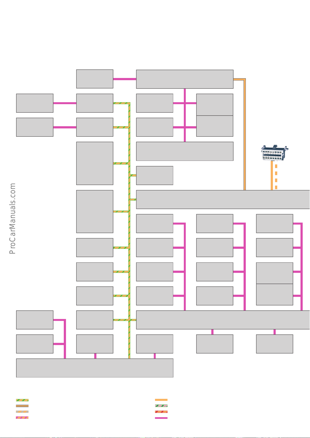
Topology
< Back
Forward >
Ξ Contents
The topology shows all control units with connectivity to the bus
systems.
Door control unit,
rear driver side
J926
Door control unit,
rear pass. side
J927
Flap control control
motors
1 –15
Driver side door
control unit
J386
Front pass. side
door control unit
J387
Seat and steering
column adjustment
control unit with
memory function
J136
Front air conditioner/Climatronic operating and
display unit
E87
Fresh air blower
control unit
J126
High pressure
sender
G65
Rear air conditioner/Climatronic operating and
display unit
E265
Electronic steering
column lock
control unit
J764
For a detailed description of the control units and the electrical
system, refer to Self Study Programme 646 "Vehicle Electrics and
Electronics".
Humidity sender in
fresh air intake
duct
G657
Air quality sensor
G238
Diagnostic port
Front passenger
seat adjustment
control unit with
memory
J521
Special vehicle
control unit
J608
Sliding sunroof
adjustment
control unit
J245
Rear hatch
control unit
J605
Heated windscreen
control unit
J505
Anti-theft alarm
sensor
G578
Trailer recognition
control unit
J345
Alarm horn
H12
Data bus diagnostic interface
J533
Seat back fan 1,
front left
V512
Seat cushion fan 1,
front left
V514
Seat back fan 1,
front right
V516
Seat cushion fan 1,
front right
V518
Electrical system control unit
J519
Rear hatch opening
control unit
J938
Garage door
operating unit
E284
Garage door opener
control unit
J530
Automatic anti dazzle rear view mirror
Y7
Roof electronics
control unit
J528
Interior light
module
Light switch
E1
Wiper motor
control unit
J400
Rain and light
detector sensor
G397
Humidity sensor
G355
Interior light
module
Central control unit for convenience system
J393
Key:
Convenience CAN
Hybrid CAN
Extended CAN
Infotainment CAN
84
Diagnostics CAN
FlexRay
Modular Infotainment Platform (MIB) CAN
LIN bus
Page 85
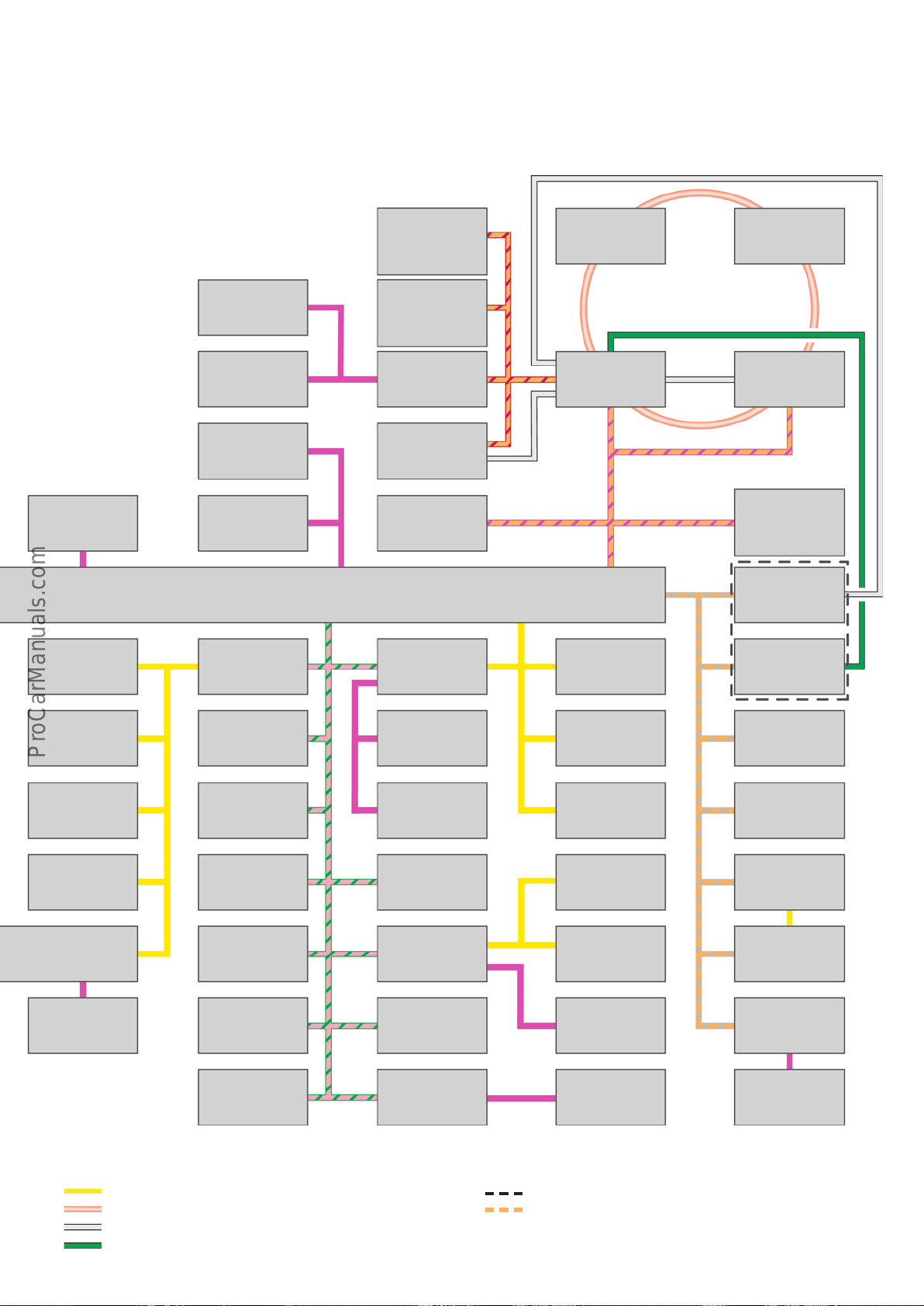
Control unit for
< Back
Forward >
Ξ Contents
rear left information display and
operating unit
J648
Digital sound package control unit
J525
TV tuner
R78
Driver side volume
control
E67
Multimedia system
key module
E817
Battery monitor
control unit
J367
Multifunction
steering wheel
control unit
J453
L/H control unit for
light control
J1018
R/H control unit for
light control
J1023
Alternator
C
Front camera for
driver assistance
systems
R242
ABS control unit
J104
Control unit for
rear right information display and
operating unit
J649
Multimedia system
operating unit
E380
MMI display
J685
Selector lever sensors control unit
J587
Engine control unit
J623
Radiator louvre
control motor
V544
Information
electronics
control unit 1
J794
sender
NO
x
control unit
J583
NO
sender
x
control unit 2
J881
Control unit in dash
panel insert
J285
Control unit for windscreen projection
(head-up display)
J898
Surround camera
control unit
J928
or
Rear-view camera
system control unit
J772
Reducing agent
metering system
control unit
J880
Left LED headlight
power module 1
A31
Right LED headlight
power module1
A27
Operating unit 1 for
drive and comfort/
convenience functions
E791
Sub-bus systems
MOST bus
LVDS
FBAS
Power steering
control unit
J500
Suspension
control unit
J775
Steering column
electronics
control unit
J527
ACC control unit
J428
All-wheel drive
control unit
J492
Radiator louvre
control motor 2
V550
Active steering
control unit
J792
Airbag control unit
J234
ACC control unit 2
J850
Automatic gearbox
control unit
J217
Particulate sensor
G784
Front left seat
belt tensioner
control unit
J854
Front right seat
belt tensioner
control unit
J855
Seat occupancy
recognition
control unit
J706
Electrical pump2
for gearbox
V553
Main beam assist
control unit
J844
Audi side assist
control unit
J769
Audi side assist
control unit 2
J770
Auxiliary heating
control unit
J364
Remote control
receiver for auxiliary
heating
R64
"OR" configuration
Ethernet port for diagnose interface VAS6154
644_114
85
Page 86
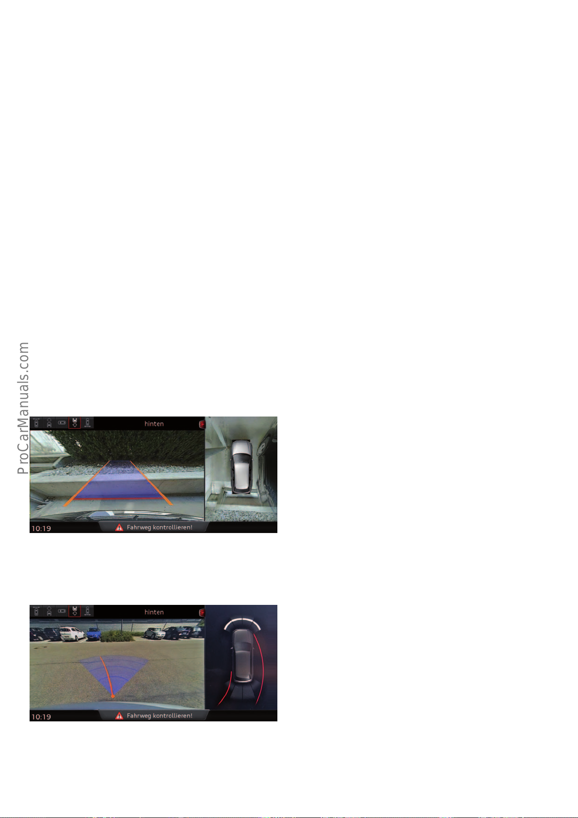
Surround cameras
< Back
Forward >
Ξ Contents
Function
The surround cameras constitute a driver assist system which is
designed to help the driver during manoeuvring and parking. A
better overview of the immediate vicinity of the vehicle helps the
driver detect obstacles or hazards outside the normal visible range.
Thus, the system can help avoid collisions.
Available views
The views from the surround cameras are always displayed in
splitscreen mode. The selected view is shown on the left-hand side
of the MMI display and takes up about ⅔of the total display area.
An image is displayed in portrait mode on the right-hand side. This
is either the graphic of the OpticalParkingSystem(OPS) of the
"overhead view" (bird's eye view) of the surround cameras.
The surround camera system comprises four wide-angle cameras
which capture the entire area around the vehicle. The cameras are
integrated in the radiator grille, in the rear hatch handle and in
both door mirrors.
The driver can choose between six dierent views: a bird's eye view
of the vehicle or images from individual cameras.
If the overhead view is already being shown on the left-hand side
of the display, the graphic of the OpticalParkingSystem(OPS) is
shown on the right-hand side.
The following six views are available to the customer:
Rear view –normal view
This view shows the area behind the vehicle. The image provided by
the rear camera is solely used for this purpose. The orange-coloured lines show the projected trajectory of the vehicle as it continues to reverse. They are dependent on the actual steering angle
and are designed to help the driver during reversing and parking. If
the red line in the image hits an obstacle, the driver should stop
reversing as there is a risk of collision.
644_159
Rear view –trailer view
To couple a trailer to the vehicle, the driver can switch to what is
known as "trailer view". A blue circular segment and an orangecoloured line are projected into the image. They help the driver
position the vehicle so that a trailer can be coupled without a great
deal of eort.
644_160
86
Page 87
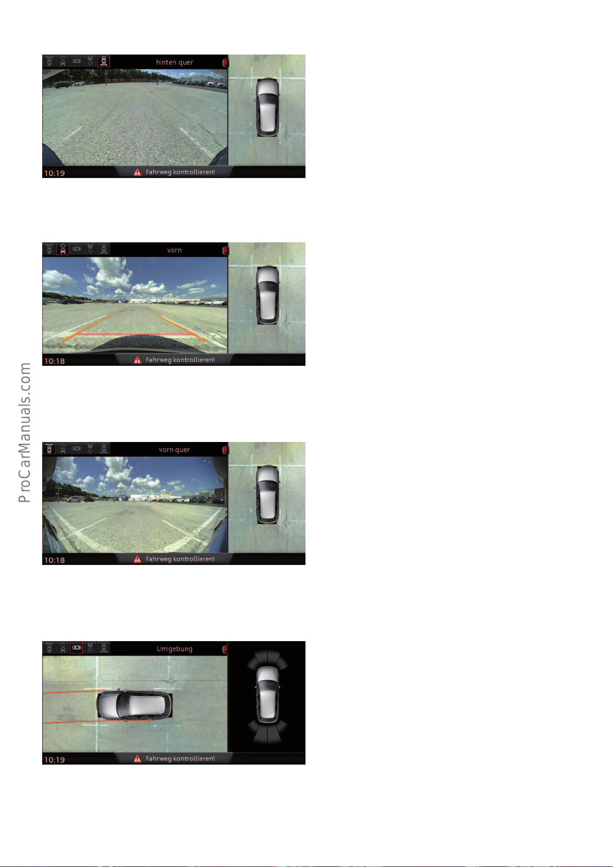
644_162
< Back
Forward >
Ξ Contents
Corner view, rear
This view represents a 180° panorama view of the area behind the
vehicle and is identical to the image from the rear camera. The
distortion of the wide-angle image in the control unit is eliminated
from this view. This view is ideal for reverse parking in impaired
visibility situations. It enables cross trac approaching from the
side to be detected earlier and helps avoid a collision. The orangecoloured lines show the projected trajectory of the vehicle as it
continues to travel forwards.
Front view
This view shows the area in front of the vehicle. The image provided by the front camera is the basis for this. The image components of the camera picture showing the front side area of the
vehicle are, however, not shown in this view.
644_161
Corner view, front
This view represents a 180° panorama view of the area in front of
the vehicle and is identical to the image from the front camera. The
distortion of the wide-angle image in the control unit is eliminated. This view helps, for example, when manoeuvring forwards
out of a perpendicular parking space in an impaired visibility
situation or when passing a narrow driveway exit. It enables cross
trac approaching from the side to be detected earlier and helps
avoid a collision.
644_163
Overhead view
This view shows the immediate vicinity of the vehicle from the
bird's eye perspective. This image is a composite of all 4 camera
pictures. However, objects above the door mirrors at the side
cannot be displayed. This is not possible because the side cameras
are installed on the undersides of the door mirrors. The two red
lines in front of the vehicle show the projected path ahead on the
basis of the steering angle.
644_164
87
Page 88
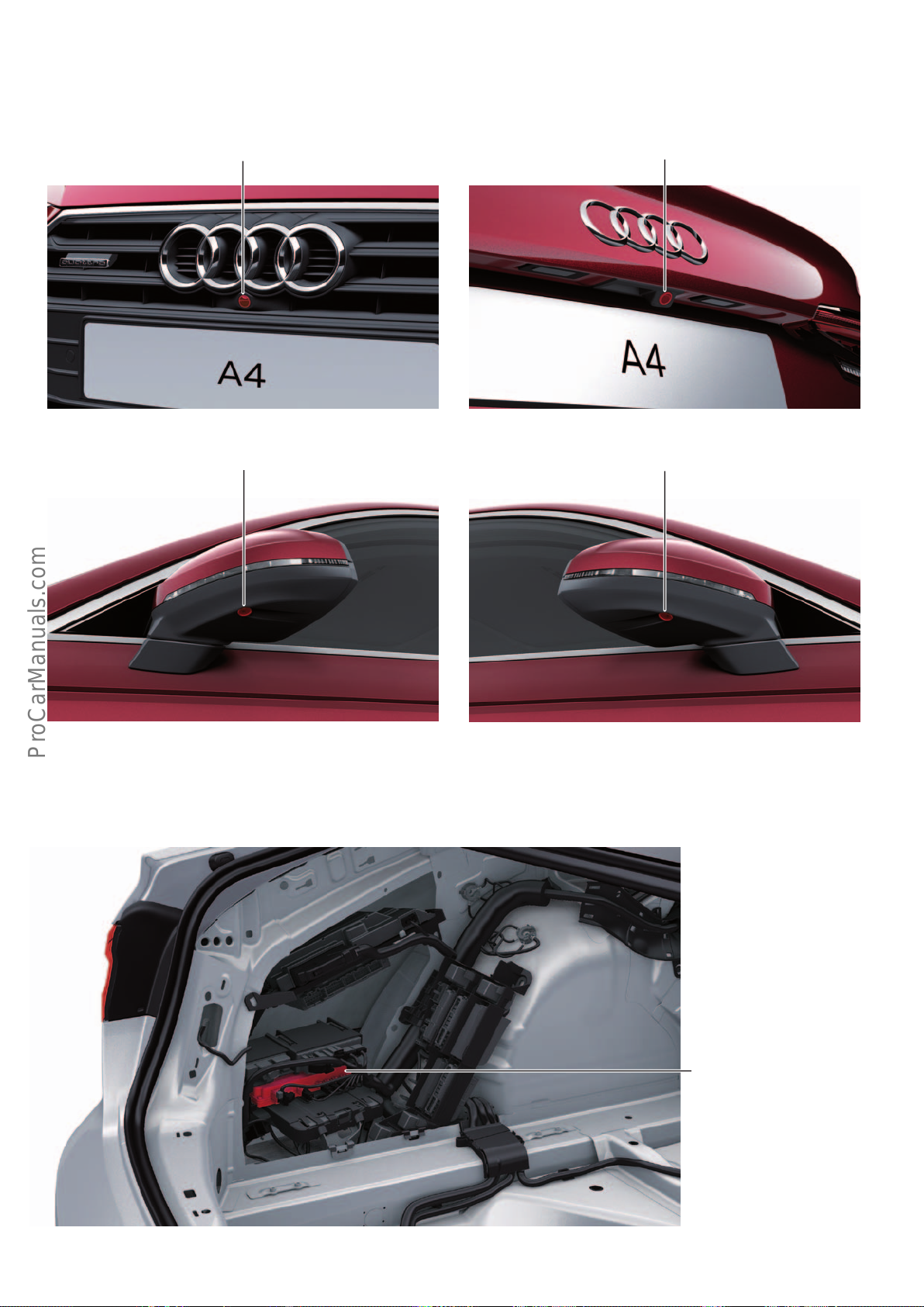
Installation locations of components in the AudiA4(type8W)
< Back
Forward >
Ξ Contents
Installation location of surround cameras R243 – R246
Front surround camera
R243
L/H surround camera
R244
Rear surround camera
R246
644_147 644_148
R/H surround camera
R245
Surround camera control unit J928
644_149
644_150
Surround camera control unit
J928
644_165
88
Page 89
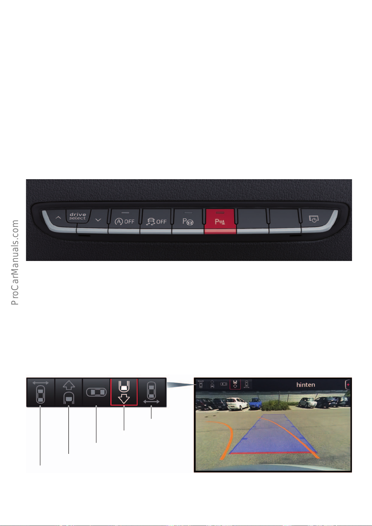
System operation
< Back
Forward >
Ξ Contents
Switching on and o
The surround cameras are a useful complement to Audi's park
assist systems. The system is able to show the entire area around
the vehicle in the form of a bird's eye view. This allows obstacles to
be recognised visually by the driver, in addition to the audible
signals generated by the parking aid.
The following actions activate the surround camera display on the
MMI screen:
• Engagement of reverse gear
• Pressing the parking aid button
The bird's eye view also covers the areas to the side of the vehicle
which are beyond the range of the parking aid sensors.
For this reason, activation of the surround cameras is coupled to
the activation and deactivation of the Audi parking aid.
The following actions deactivate the surround camera display:
• Travelling forwards at a speed of greater than 10 kph
• Pressing the parking aid button again
• Turning o the ignition
Selecting the desired view
The driver can select the desired view using the turn-push button
on the MMI panel. The following option is available for this
purpose at the edge of the MMI screen.
Corner view, rear
Rear view
644_166
Overhead view
Front view
Corner view, front
644_167
89
Page 90
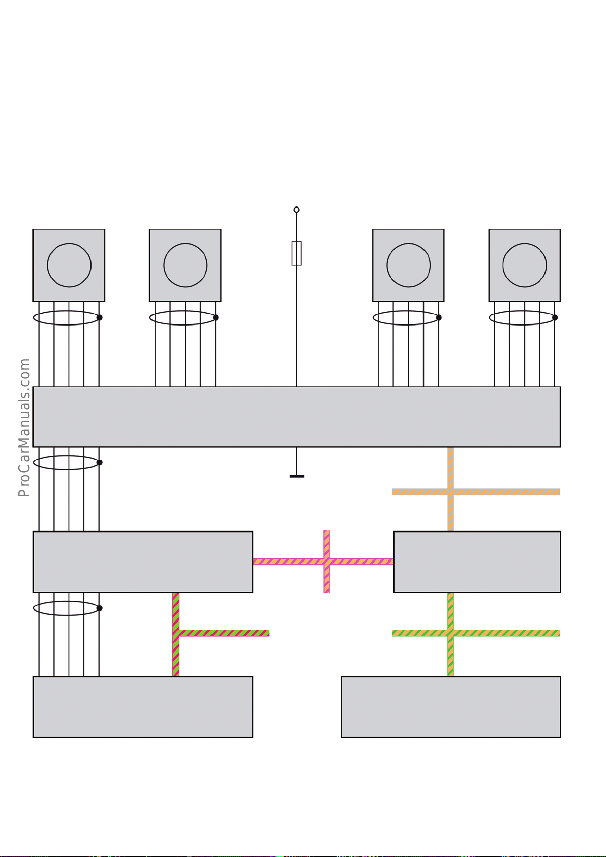
Implementation of the function in the vehicle
< Back
Forward >
Ξ Contents
The images provided by the four surround camerasR243–R246
are transmitted to the surround cameracontrol unit J928 via a
shielded Ethernet connection. This connection transmits the
Front
surround
camera
R243
Left
surround
camera
R244
requested image via a shielded LVDS connection to the information
electronics control unitJ794, which in turns sends the image via a
shielded LVDS connection to the MMI displayJ685.
Terminal 30
5A
Right
surround
camera
R245
Rear
surround
camera
R246
Ethernet -LVDS -LVDS -
VCC
Ground
Shield (ground)Shield (ground)Shield (ground)
Ethernet +
Ethernet +
Surround camera control unit
J928
GroundGround
GroundGround
LVDS +LVDS +
Information electronics
control unit 1
J794
VCC
Ethernet -
Ground
Modular Infotainment
Platform CAN
Shield (ground)
Terminal 31
Infotainment CAN
Ethernet +
Ethernet -
Gateway
J533
VCC
Ethernet +
Ethernet -
Ground
VCC
Ground
Shield (ground)
Extended CAN
Convenience CAN
Shield (ground)
MMI display
J685
90
Electrical system control unit
(parking aid system)
J519
644_146
Page 91
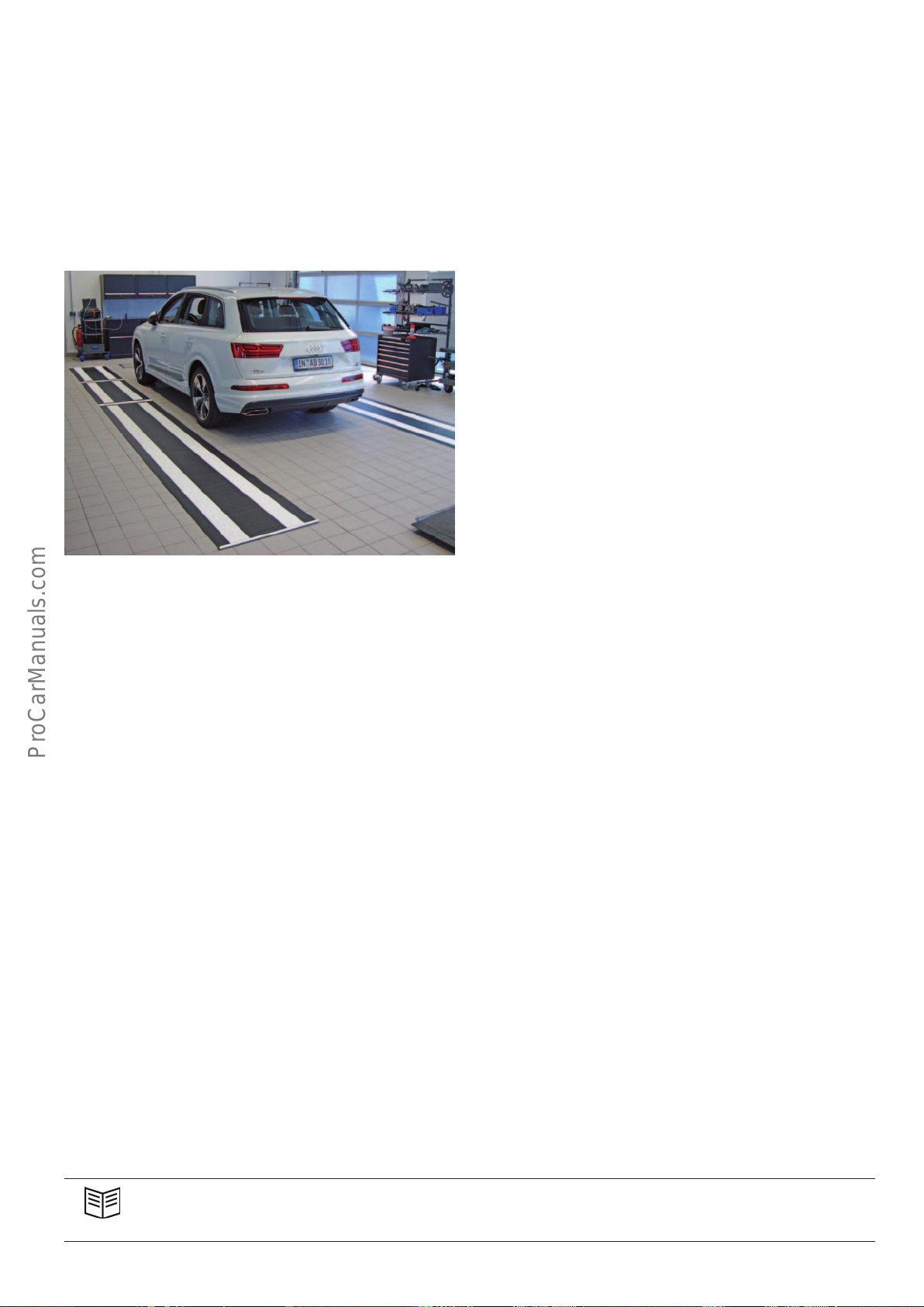
Calibration tools VAS6350 and VAS721001
< Back
Forward >
Ξ Contents
There are currently two dierent generations of the Audi surround
camera. The first-generation surround camera is oered in models
launched prior to the AudiQ7(type4M). The second-generation
surround camera was introduced in the AudiQ7(type4M). It is
also available in the AudiA4(type8W).
Depending on generation, two dierent special tools are needed to
calibrate the surround camera.
• For the first generation: special tools VAS6350 and
VAS6350/6
• For the second generation: special tool VAS721001
Calibrating the second-generation surround camera
To calibrate the second-generation surround cameras, two socalled calibration mats (VAS721001) are rolled out at the sides of
the vehicle. Both calibration mats are identical. After this, they are
aligned with the vehicle as specified in the Workshop Manual.
Finally, the calibration program is started on the diagnostic tester.
It takes only a few seconds to successfully complete the calibration
routine.
Calibrating the first-generation surround camera
When calibrating the first-generation surround cameras, each
camera is calibrated individually. This means that the calibration
tool has to be realigned for each camera. This process is much
more time-consuming. First-generation surround cameras can only
be calibrated using special tools VAS6350 and VAS6350/6.
644_151
Each of the two calibration mats is approx.8m long. Due to the
length and alignment of the calibration mats, each mat can be
viewed simultaneously by 3 surround cameras. Depending on the
side of the vehicle, these are the left or right side camera and the
two front and rear cameras. Due to this fact, all four cameras can
be calibrated simultaneously after aligning both calibration mats.
Reference
For information about other driver assistance systems in the Audi A4, refer to Self Study Programme635 "AudiQ7(type4M)
Driver Assistance Systems".
91
Page 92
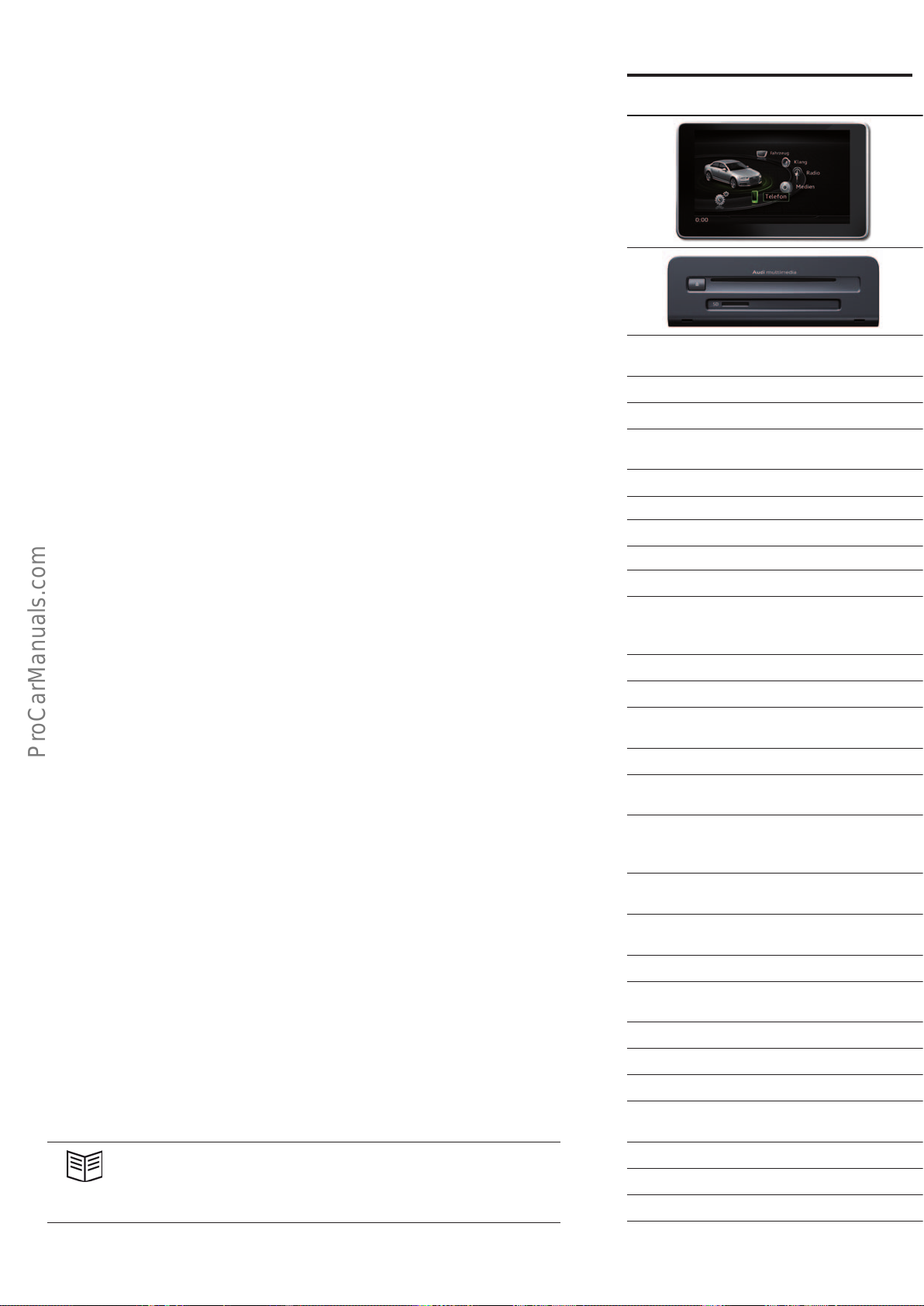
Infotainment
< Back
Forward >
Ξ Contents
The infotainment package for the AudiA4 (type8W) has been
completely revised compared with the previous model. The AudiA4
is the first Audi model to feature the second-generation MIB Scale.
Overview of versions
Three versions of the MMI are available for the Audi A4:
• MMI Radio plus
• MMI Navigation
• MMI Navigation plus
MMI Radio plus (I8E) MMI Radio plus (I8S) with
From a technical point of view, MMI Radio plus is identical to the
second-generation MIB Standard.
The MMIRadioplus with Connectivity Package and MMINavigation
are based on the new MIBScale line.
MMINavigationplus is a second-generation MIBHigh system.
1)
7UH for countries without navigation map data
2)
EL0 for markets without Audi connect
3)
2x HFP (2mobile phones can be coupled via Hands-Free Profile)
4)
For markets in which no coupling box (external aeria connection for smartphone) is
available.
5)
The Audi connect data module will then become a fully fledged telephone module mit
SAP (SIM Access Profile).
6)
If digital radio (QV3) and TV tuner (QV1) are ordered together, the PRNR is QU1.
7)
Auto SOS only (IW1) or Auto SOS and Service (IW3), depending on country
7.0“ TFT colour monitor with 800x480pixel
resolution
Without navigation (7Q0) Pre-wiring for navigation unit (7UH) 3D SD navigation (7UG) 3D SSD navigation (7UG)
Basic operating unit Mid operating unit Mid operating unit MMI touch
5“ monochrome display in instrument cluster
with driver information system (9S5)
AM/FM radio AM/FM radio AM/FM radio AM/FM radio
CD drive (MP3, WMA, AAC) CD drive (MP3, WMA, AAC) CD drive (MP3, WMA, AAC) DVD drive (audio/video)
1 SDXC card readers 2 SDXC card readers 2 SDXC card readers 2 SDXC card readers
AUX-in jack and 5V USB charging port (UE3) Audi music interface and Audi smartphone
Basic sound system (8RM) Basic sound system (8RM) Basic sound system (8RM) Basic sound system (8RM)
Bluetooth interface (9ZX) Bluetooth interface (9ZX) Bluetooth interface (9ZX) Bluetooth interface (9ZX)
Optional equipment
7“ display in instrument cluster with driver
information system (9S7)
Audi music interface with 2 USB ports and
AUX-In jack (UE7)
Audi phone box including wireless charging
2)
(9ZE)
Audi phone box light
(for wireless charging only) (9ZV)
3),4)
Audi sound system (9VD) Audi sound system (9VD) Audi sound system (9VD) Audi sound system (9VD)
Bang & Olufsen Sound System with 3D sound
(9VS)
Digital radio DAB (QV3)
6)
92
Reference
For further information about the infotainment system and Audiconnect,
refer to Self Study Programme647 "AudiA4 (type8W) Infotainment and
Audiconnect".
Audi Auto SOS & Audi connect
vehicle-related services (IW3)
7)
Prewiring for Rear Seat Entertainment (9WM) Prewiring for Rear Seat Entertainment (9WM) Prewiring for Rear Seat Entertainment (9WM) Prewiring for Rear Seat Entertainment (9WM)
Page 93
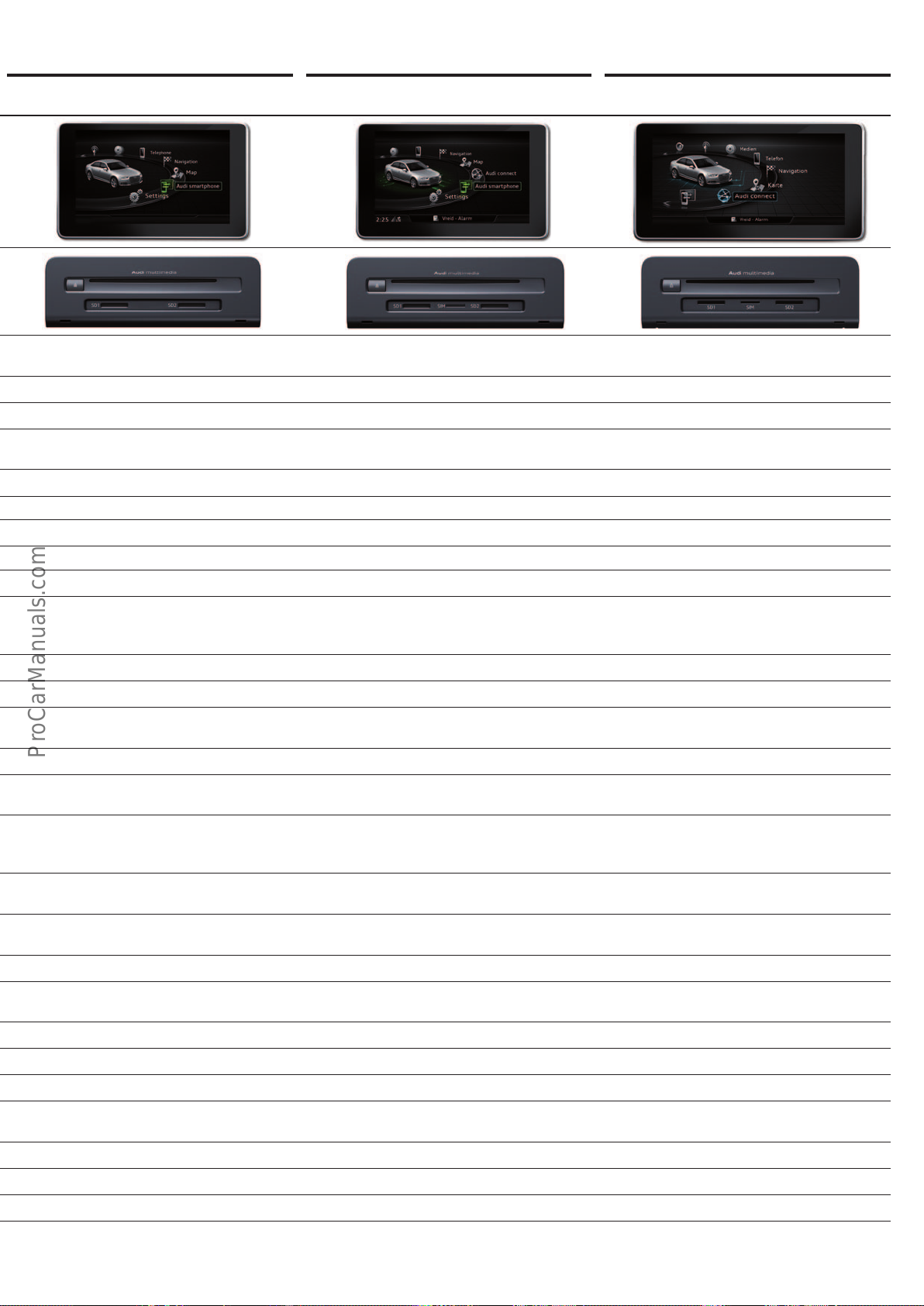
Connectivity Package (PNV)
< Back
Forward >
Ξ Contents
MMI Navigation (I8S) MMI Navigation plus (I8H)
7.0“ TFT colour monitor with 800x480pixel
resolution
5“ monochrome display in instrument cluster
with driver information system (9S5)
interface with 2 USB ports and
AUX-In jack (UI2)
7“ display in instrument cluster with driver
information system (9S7)
Audi phone box including wireless charging
3)
(9ZE)
Audi phone box light
(for wireless charging only) (9ZV)
3),4)
7.0“ TFT colour monitor with 800x480pixel
resolution
5“ monochrome display in instrument cluster
with driver information system (9S5)
8.3“ TFT colour monitor with 1024x480pixel
resolution
1)
)
7“ display in instrument cluster with driver
information system (9S7)
Satellite radio for North America (Sirius) (QV3)
Jukebox (10GB)
AUX-in jack and 5V USB charging port (UE3) AUX-in jack and 5V USB charging port (UE3)
2)
UMTS/LTE data module (EL32) UMTS/LTE data module (EL3)
including
Audi connect (IT1)
7“ display in instrument cluster with driver
Audi virtual cockpit (9S8)
information system (9S7)
Audi music interface and Audi smartphone
interface with 2 USB ports and
AUX-In jack (UI2)
Audi phone box including wireless charging
3),5)
(9ZE)
Audi phone box light
(for wireless charging only) (9ZV)
3),4),5)
Audi music interface and Audi smartphone
interface with 2USB ports and
AUX-In socket (UI2)
Audi phone box and wireless charging
3),5)
(9ZE)
Audi phone box light
(for wireless charging only) (9ZV)
3),4),5)
Bang & Olufsen Sound System with 3D sound
(9VS)
Digital radio DAB (QV3)
6)
Audi Auto SOS & Audi connect
vehicle-related services (IW3)
7)
Bang & Olufsen Sound System with 3D sound
(9VS)
Digital radio DAB (QV3)
TV tuner (QV1)
6)
6)
Audi connect (IT1)
Audi Auto SOS & Audi connect
vehicle-related services (IW3)
7)
Bang & Olufsen Sound System with 3D sound
(9VS)
Digital radio DAB (QV3)
TV tuner (QV1)
6)
6)
Audi Auto SOS & Audi connect
vehicle-related services (IW3)
7)
1Audi tablet (9WE)
2Audi tablet (9WF)
93
Page 94
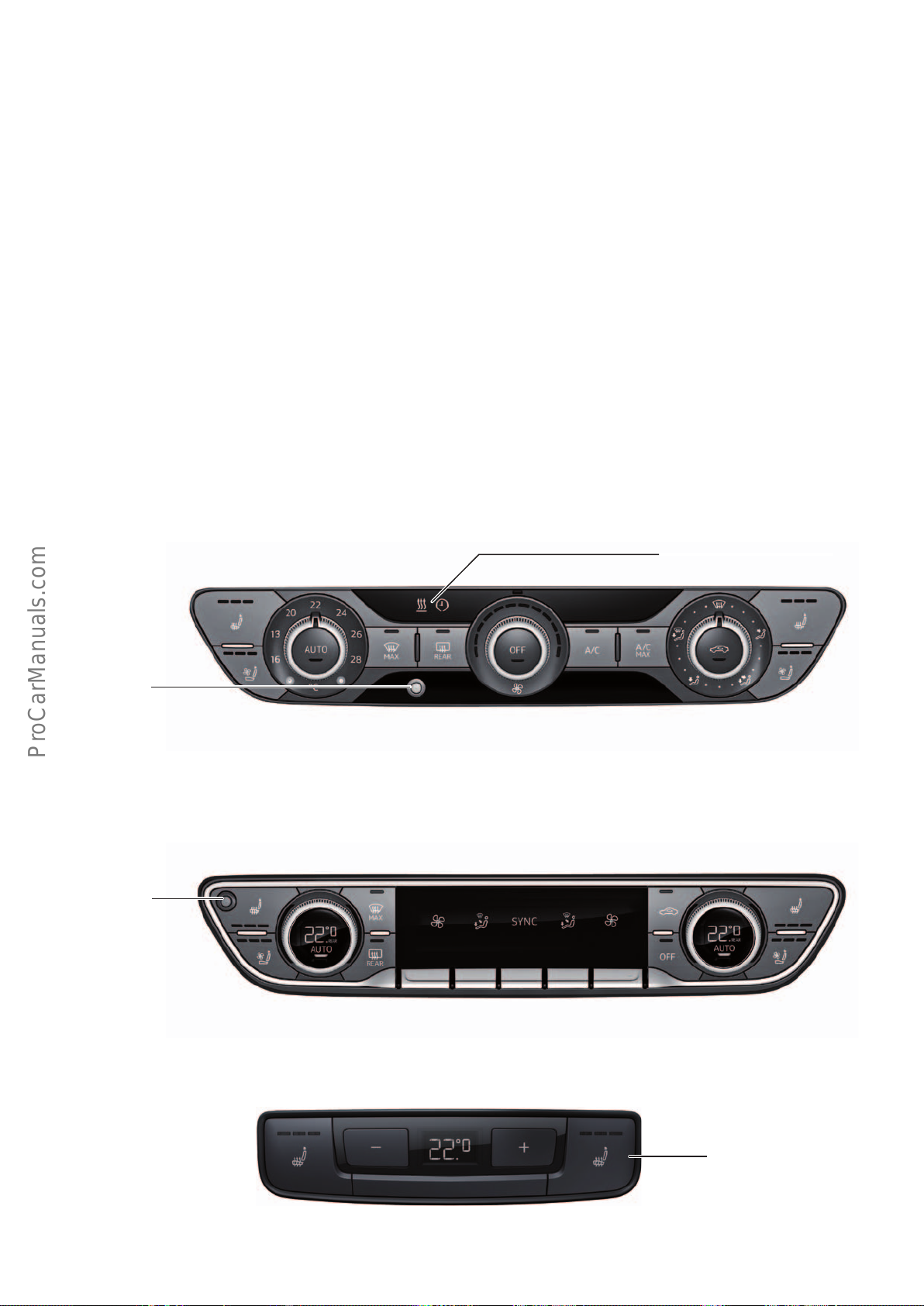
Air conditioning
< Back
Forward >
Ξ Contents
Introduction
Single-zone automatic air conditioning is standard in the AudiA4
(type8W) and three-zone automatic air conditioning is optional.
Both air conditioning systems have an ecient refrigerant circuit
with an internal heat exchanger.
Operation
Technically, the front air conditioning/Climatronic display and
control panel E87 of the 3-zone deluxe automatic air conditioning
system is identical to the operating unit from the
AudiQ7(type4M). The temperature displays are integrated in the
Single-zone automatic air conditioning
Both in fresh air mode and circulation mode, a combined activated
carbon filter filters out the tiniest of fine dust particles.
The wide air outlet strip in the deluxe automatic air conditioning
system allows indirect ventilation. It also increases the circulating
air flow.
rotary dials and the air conditioning system can be operated with
just a few buttons and capacitive rocker switches. In the case of
3-zone deluxe automatic air conditioning, a separate control panel
with a digital display is available for the rear cabin.
Auxiliary heating/ ventilation display
Cabin temperature
sensor
3-zone deluxe automatic air conditioning
Cabin temperature
sensor
Rear control panel
644_021
644_022
Seat heating, rear
(optional)
644_023
94
Page 95
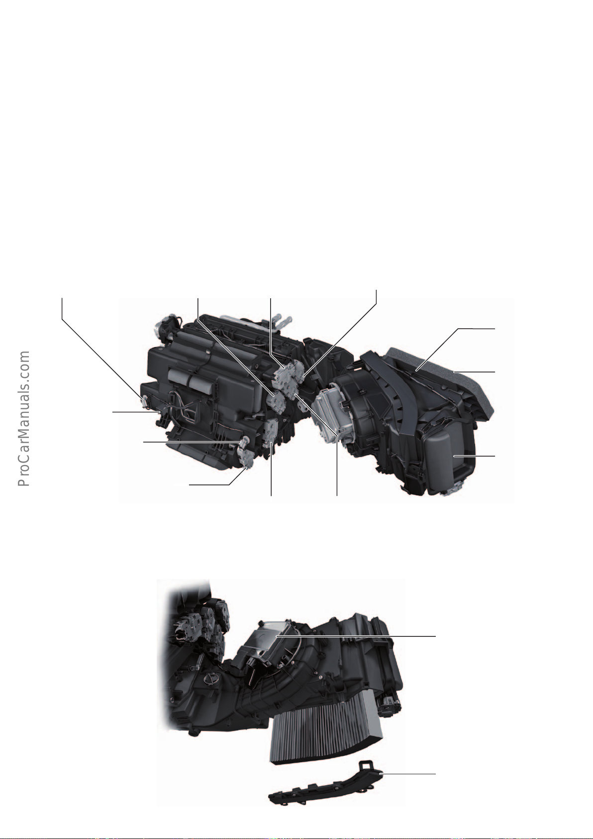
Air conditioners
< Back
Forward >
Ξ Contents
Control motors
The air conditioners in the AudiA4 (type8W) and the
AudiQ7(type4M) are identical in design and dier only in specification and in the number of installed control motors.
The air conditioners for the new AudiA4 have the following special
features:
• If repair work is needed, the following components of the air
conditioner can be removed and replaced without removing the
dash panel:
• Control motors
• Heat exchanger
• Auxiliary heating heating element Z35 with auxiliary air
heater control unit J604
• Fresh air blower V2 with fresh air blower control unit J126
• Heater matrix
Left footwell vent
temperature sender
G261
Side vent control motor,
right
V300
Centre vent control motor,
right
V111
The control motors are all identical in design and are programmed
by auto addressing.
If repair work is needed, the cables and plugs leading to the
control motors and the cable connections to the temperature
sensor must not be interchanged because the components could
otherwise be incorrectly addressed.
Right temperature flap control motor
V159
Air intake box
Air conditioner
Right footwell vent temperature sender
G262
Rear air distributor flap control motor
V427
Rear air quantity control motor
V443
Fresh air blower
Footwell flap control motor,
right
V109
Right footwell temperature
flap control motor
V412
Fresh air inlet
Circulated air inlet
644_024
Fresh air blower
V2
Fresh air blower control unit
J126
Shaft cover of dust and pollen
filter, in front pass. footwell
644_025
95
Page 96
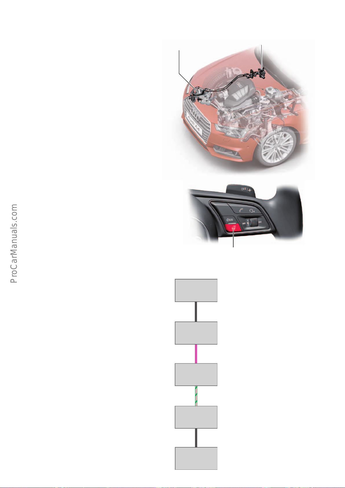
Auxiliary heating
< Back
Forward >
Ξ Contents
Auxiliary heating is optional for the AudiA4. Auxiliary heating is a
comfort equipment option which can be used to heat or ventilate
the vehicle.
As with the AudiQ7(type4M), the auxiliary heating can be
switched on and programmed with the remote control and via the
Auxiliary heating option in the MMI menu or, in the case of the
3-zone deluxe climate control system, via the front air conditioning/Climatronic display and control panel E87.
The auxiliary heating primarily heats the interior when in heating
mode. The heater coolant shut-o valve N279 quickly warms the
interior.
In connection with the optional Audi connect operating system,
the auxiliary heating of the AudiA4 can be conveniently operated
and programmed with a smartphone app.
Steering wheel heating
The steering wheel rim can be heated electrically with the steering
wheel heating button. The instrument cluster display indicates
whether the steering wheel heating is on or o.
Once activated, the steering wheel heating maintains a nearconstant temperature (the temperature is preset).
The setting of the steering wheel heating is stored automatically
and assigned to the ignition key in use.
Auxiliary heating with auxiliary
heating control unit
J364
Coolant shut-o valve
N297
644_026
Activation
The steering wheel heating receives its electrical power from the
steering column electronics control unit J527.
The information provided by the steering wheel heating button
integrated in multifunction buttons on right in steering wheel
E441 is transferred discretely to the multifunction steeering wheel
control unit J453. This, in turn, transfers the data via LIN data bus
to the data bus diagnostic interface J533. After that, the information is sent by FlexRay to the steering column electronics control
unit J527.
Multifunction buttons on right in
steering wheel
E441
Discrete cable
Multifunction
steering wheel
control unit
J453
LIN bus
Data bus diagnostic interface
J533
FlexRay
Steering column
electronics
control unit
J527
644_028
Steering wheel heating button, integrated in
multifunction buttons on right in steering wheel
E441
96
Heated
steering wheel
Z36
Discrete cable
644_029
Page 97
Service
Ξ Contents
< Back
Forward >
Inspection and maintenance
The following service intervals are displayed: • Oil change service
• Mileage-based service events
• Time-based service events
Example of a service interval display in the Audi virtual cockpit
Servicing & checks Service intervals
Flexible service event
Mileage-based service event
Reset oil change interval
In new vehicles, the next oil change due field (flexible servicing
event) is initially blank.
This interval has to be computed from the driving profile and
engine load and is not displayed until about 500 km have been
covered.
Changing the oil According to service interval display, between 15,000 km/1 year and
Inspection 30,000 km /
Pollen lter change interval 60,000 km /
Air lter change interval 90,000km 90,000 km 90,000 km 90,000 km
Next oil change in
-- km / -- days
Next inspection in
30,000 km / 730 days
644_014
The value displayed in the mileage-based servicing events field is
now 30,000 km for new vehicles and is decremented in increments
of 100 km. The value in the field for the time-based servicing
events is now 730 days (2 years) for new vehicles and is updated on
a daily basis (upwards of a total mileage of about 500 km).
1.4l TFSI 2.0l TFSI 2.0l TDI 3.0l V6 MPI
30,000km / 2years depending on driving style and conditions of use.
2years
2years
30,000 km /
2years
60,000 km /
2years
30,000 km /
2years
60,000 km /
2years
Time-based service event
30,000 km /
2years
60,000 km /
2years
Brake uid change interval Change after
3, 5, ... years
Spark plug change interval 60,000 km /
6years
Fuel lter change interval – – 90,000km 90,000km
Timing gear 210,000km
Timing belt
Gear oil change interval
1)
Stronic
Note
The specifications in the current service literature generally apply.
1)
Change after
3, 5, ... years
60,000 km /
6years
Chain (lifetime) 210,000km
60,000km
Change after
3, 5, ... years
– –
Timing belt
Change after
3, 5, ... years
Chain (lifetime)
97
Page 98
Overview of maintenance intervals for vehicles in the USA
< Back
Forward >
Ξ Contents
The Audi A4 is subject to fixed inspection and maintenance intervals in the USA.
USA
Oil change serviceOil change service
10,000miles /
1 year
Inspection with oil changeInspection with oil change
20,000miles /
2 years
Oil change serviceOil change service
30,000miles /
3 years
Overview of maintenance intervals for vehicles in Canada
The Audi A4 is subject to fixed inspection and maintenance intervals in Canada.
Canada
Inspection with oil changeInspection with oil change
40,000miles /
4 years
Oil change serviceOil change service
50,000miles /
5 years
644_034a
15,000 km /
1 year
30,000 km /
2 years
45,000 km /
3 years
Overview of maintenance intervals for cars in China
The Audi A4 is subject to fixed inspection and maintenance intervals in the China.
China
Inspection with oil change
Inspection with oil change
60,000 km /
4 years
Inspection with oil change
75,000 km /
5 years
644_034b
Inspection with oil change
10,000 km /
365 days later
98
20,000 km /
365 days later
30,000 km /
365 days later
40,000 km /
365 days later
644_035
Page 99
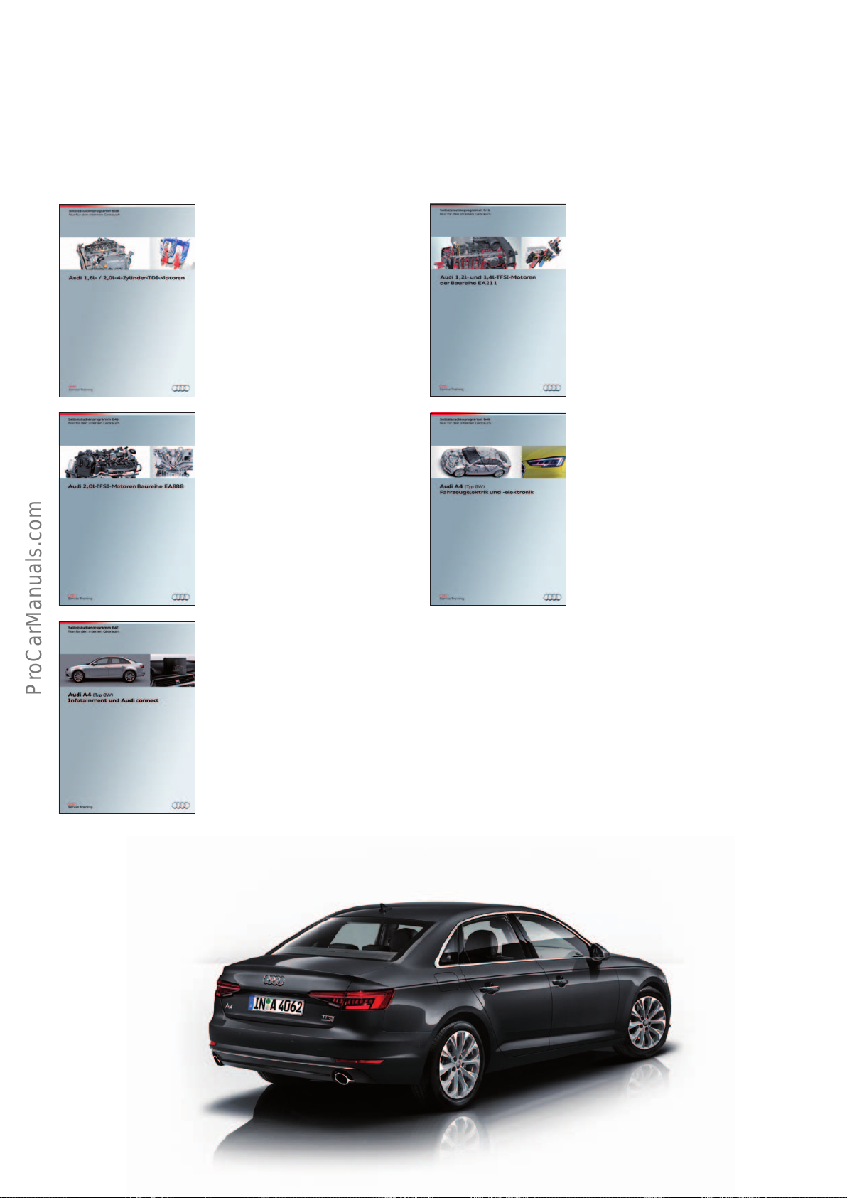
Self study programmes
< Back
Forward >
Ξ Contents
For more information about the technology of the AudiA4, please
refer to the following self study programmes.
SSP608 Audi 1.6land 2.0l 4-cylinder
TDI engines
Order number: A12.5S00.92.20
SSP645 Audi 2.0l TFSI engines
of EA888 series
Order number: A15.5S01.32.20
SSP 616 Audi 1.2l and 1.4l TFSI
engines of the EA211 series
Order number: A12.5S01.00.20
SSP646 Audi A4 (type 8W)
Vehicle electrics and electronics
Order number: A15.5S01.31.20
SSP647 Audi A4 (type 8W)
Infotainment and Audi connect
Order number: A15.5S01.29.20
99
Page 100

Audi Vorsprung durch Technik
644
All rights reserved.
Technical specifications are
subject to change.
Copyright
AUDI AG
I/VK-35
[email protected]
AUDI AG
D-85045 Ingolstadt
Technical status 07/15
Printed in Germany
A15.5S01.28.20
 Loading...