


TI035
TI035 400-035-001-C 13/3/07 1/2
TI035
Installation and User Guide
Programmable Wall Switch
The TI035 programmable wall switch has been designed to control lightings
and motors:
NOTE: This switch cannot be used if there are not at least 2 white wires joined
by a connector inside the electrical box.
n Cut power at the circuit breaker to avoid electric shock.
o Remove the existing switch.
p Install the new switch as shown in the diagram below.
q Apply power at the circuit breaker.
n Pry the switch door open from the bottom
using a small screwdriver.
o Ensure the ON/OFF selector is set to ON.
p Reset the switch using a paper clip. 0:00
will flash.
If the display is blank:
• Ensure the ON/OFF selector is properly
engaged in the ON position. Push it to the
right using a small screwdriver.
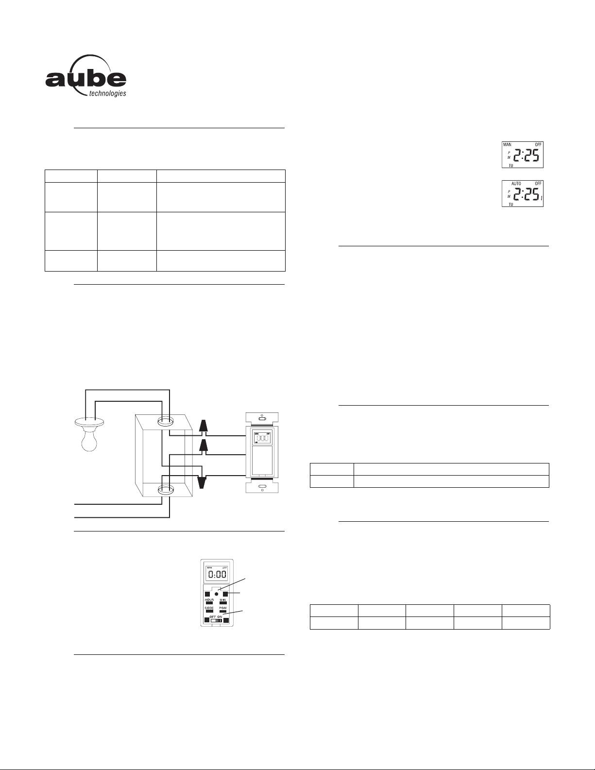
The programmable switch has 2 operating modes: manual (MAN) and
automatic (AUTO).
To switch mode, press the switch door for 3 seconds.
Manual Mode
The programmable switch operates as a regular switch.
Briefly press the switch door to turn the lights On or Off.
The mode (MAN) and state (ON or OFF) are displayed.
Automatic Mode
The programmable switch follows the programmed
schedule. The mode (AUTO), state (ON or OFF) and
current program number are displayed.
To temporarily override the programmed schedule, briefly
press the switch door. The new state (ON or OFF) will flash
to show that the state is temporary. The override remains in effect until you
press the switch door again or until the beginning of the next program.
NOTE: The switch displays the time in 24-hour format by default or following a
reset.
n To switch between 12-hour format and 24-hour format, proceed as
follows:
a) Press one of the control buttons to ensure the MAN or AUTO indica-
tor is displayed.
b) Press the MIN and HOUR buttons simultaneously and brieftly (0:00
display = 24-hour; 12:00 display = 12-hour ).
o Set the time using the HOUR and MIN buttons. For the 12-hour time
format, if you are setting an afternoon time, ensure PM appears on the
screen.
p Press one of the control buttons or close the switch door to return to
normal operation.
This procedure sets the switch for daylight savings time or for standard time.
n Press the CODE button four times.
o Press the MIN button to switch between nor and Ad.
p Press one of the control buttons or close the switch door to return to nor-
mal operation.
NOTE: By default, once you have programmed the sunset/sunrise
parameters, the timer will follow the sunrise/sunset program when placed in
Automatic mode. To set your own schedule, see section 8.
7.1 Determining the sunset/sunrise parameters
Fill out the following table:
1) LATITUDE & LONGITUDE: Enter the coordinates of your city or the
nearest city using the supplied table. If none of the cities in the table is appli-
cable, this information is usually available on the internet.
NOTE: Add a minus sign when entering a south latitude coordinate or a west
longitude coordinate.
n
Applications
1.
Load type Maximum load Examples
Resistive load
2400 W
(20 A @ 120 V)
• incandescent lights
• halogen lights
• block heater
Inductive load
2400 W
(20 A @ 120 V)
• fluorescent lights
• compact fluorescent lights (CFL)
• sodium lamps
• electronic ballasts
Motor 1 hp
• pool filter pumps
•fans
o
Installation
2.
p
Power-on
3.
q
Operating Modes
4.
120 VAC
white (neutral)
black (line)
white
black
white
black
blue
Control (4)
Reset
On/Off
selector
r
Setting the Clock
5.
s
Daylight Savings Time
6.
nor Standard time / Normal time / Winter time
Ad Daylight savings time / Advanced time / Summer time
t
Sunset/Sunrise Program
7.
Latitude Longitude Day # nor/Ad Lc
TI035 400-035-001-C 13/3/07 2/2
2) DAY #: Enter the day #. (Add the code of the current month to the current
date.)
For example: For June 24th, the day # = 151 + 24 = 175
3) nor/Ad: If your country has daylight savings time, select the appropriate
period.
4) Lc: If your city’s time zone is based on political or economic boundaries
instead of its coordinates, your lights might switch On/Off too early or too late
with respect to sunrise and sunset. Therefore, apply a correction factor (+1 or
-1). Otherwise, leave it at 0.
7.2 Programming the sunset/sunrise parameters
Once you have completed section 7.1, proceed as follows:
n Press the CODE button until the desired parameter appears. The param-
eters appear in the following order.
o Press the HOUR or MIN button to modify the value (see table above for
the buttons to use).
p Press one of the control buttons or close the switch door to return to nor-
mal operation.
NOTE: This section allows you to set your own schedule.
The switch can hold 2 programs which are repeated every day. When you
place the timer in Automatic mode, it will activate the load at the start of each
program and deactivate it at the end of the program. You need to set the fol-
lowing parameters:
n Press the PGM button until the desired parameter is displayed.
If you have entered your city’s parameters (see section 7), the
parameters P1 ON and P2 OFF show the sunset time and sunrise time
for this time of the year. If the timer is used for lighting, when placed in
AUTO mode, it will turn the light ON at sunset and will turn it Off at
sunrise. For example:
o Press the HOUR and MIN buttons to set the time.
Example: If you want your lights to turn On at sunset and to turn Off at
10:00 PM, set P1 OFF to 22:00. If you also want your lights to turn back
On at 5:00 AM then turn Off at sunrise, set P2 ON to 5:00.
NOTE: P1 OFF and P2 OFF have priority over P1 ON and P2 ON
respectively. For example, if sunrise is at 4:58 and P2 ON is set to 5:00,
the lights will not turn on.
You can replace the sunrise and sunset times by fixed times. Select
program P1 ON or P2 OFF and enter the desired time using the HOUR
and MIN buttons.
p Press one of the control buttons or close the switch door to return to
normal operation.
Clearing a programmed time
n Press the PGM button to display the programmed time.
o Press the CODE button. The time will be erased and -:-- will be
displayed.
NOTE: For P1 ON and P2 OFF, if you have programmed the city
parameters, the programmed time will be replaced by sunset time and
sunrise time respectively.
p Press one of the control buttons or close the switch door to return to
normal operation.
Supply: 120 VAC, 50 / 60 Hz
Maximum load: 2400 watts resistive or inductive, 1 HP motor
Operating temperature range: 5°F to 122°F (-15°C to 50°C)
Storage temperature range: -4°F to 122°F (-20°C to 50°C)
Power outage: The programs are protected by a rechargeable battery. The
screen is blank during the power outage.
Solar table precision: +/- 11 min. (max error around poles)
Certifications: CSA & UL
January 0 May 120 September 243
February 31 June 151 October 273
March 59 July 181 November 304
April 90 August 212 December 334
nor Standard time / Normal time / Winter time
Ad Daylight savings time / Advanced time / Summer time
Parameter Default
setting
Possible
settings
Buttons
used
Latitude (LAT) 00 -65 to 65 HOUR & MIN
Longitude (LONG) 000 -180 to 180 HOUR & MIN
Day number (DAY #) 000 1 to 365 HOUR & MIN
Daylight savings time nor nor / Ad MIN
Local correction factor (Lc) 0 -1, 0, 1 MIN
u
Programming the Schedule
8.
P1 ON : Start time of program 1
P1 OFF : End time of program 1
P2 ON : Start time of program 2
P2 OFF : End time of program 2
P1 ON : 20:38 (sunset)
P1 OFF : --:-- (blank)
P2 ON : --:-- (blank)
P2 OFF : 6:10 (sunrise)
P1 ON : 20:38 (sunset)
P1 OFF : 22:00 (programmed)
P2 ON : 5:00 (programmed)
P2 OFF : 6:10 (sunrise)
v
Troubleshooting
9.
Blank display • Verify circuit breaker at main panel.
• Ensure the ON/OFF selector is at ON.
• Reset the switch using a paper clip.
Faded or irregular
display
Ambient temperature below freezing point
Cannot switch between 24-
hour format and
12-hour format
First, press one of the control buttons so that
MAN or AUTO appears on display.
Programs do not run as
expected
• Make sure the switch is properly programmed.
• Note that -:-- indicates an inactive program,
00:00 indicates midnight.
• If the switch has been configured for
12-hour format, check that PM appears on the left
side of the screen when an afternoon time is dis-
played.
The switch resets itself with-
out apparent reason when
used to control an inductive
load such as a relay or a
contactor.
The reset is caused by the load. Install a snubber
(AC130-03) at each relay/contactor.
After I have bypassed the
program to turn the light Off,
it turns back On at midnight.
Any temporary bypass is cancelled at midnight.
Thus, the light has turned back On, the state the
light should be at midnight according to the pro-
gram. If you often bypass programming before
midnight, you should program P1 OFF to midnight
or earlier. This ensures that the light will remain
Off when you bypass programming.
w
Technical Specifications
10.
 Loading...