

ATX Q-Power BAQ-UP Installation & Operation Manual
BAQ-UP™ (QRED) Redundancy Switch
Q-SERIES® Power
with Backup Amplier
Installation & Operation Manual

Although every effort has been taken to ensure the accuracy of this document it may be necessary, without notice, to make amendments or correct omissions.
Specications subject to change without notice.
Q-Series® is a registered trademark of ATX in the United States and/or other countries. Products or features contained herein may be covered by one or more U.S. or foreign
patents. Other non-ATX product and company names in this manual are the property of their respective companies

TABLE OF CONTENTS
Page
1. DESCRIPTION OF INTERFACES ............................................................................................................. 1-1
2. DESCRIPTION OF OPERATION ............................................................................................................... 2-1
2.1. Functional Schematic ........................................................................................................................ 2-2
3. SET-UP PROCEDURE ..............................................................................................................................3-1
4. SPECIFICATIONS ..................................................................................................................................... 4-1
5. SERVICE & SUPPORT ..............................................................................................................................5-1
5.1. Contact ATX Networks ....................................................................................................................... 5-1
5.2. Warranty Information ......................................................................................................................... 5-1
Q-Series® Power – BAQ-UP™ (QRED) Redundancy Switch with Backup Amplier – Installation & Operation Manual i

ii Q-Series® Power – BAQ-UP™ (QRED) Redundancy Switch with Backup Amplier – Installation & Operation Manual
This page left intentionally blank.
DESCRIPTION OF INTERFACES
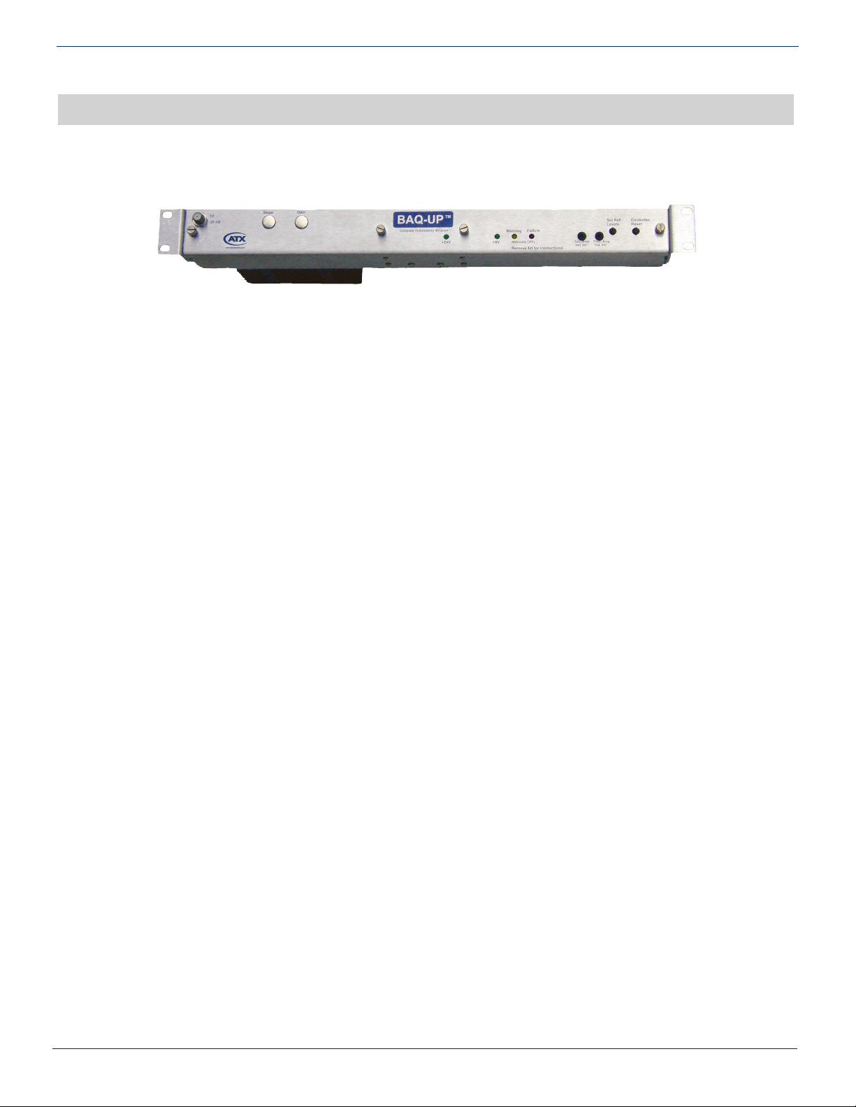
1. Description of Interfaces
BAQ-UP™ Front View
The BAQ-UP™ system (the system) has three compartments: the amplier compartment, the power supply compartment,
and the RF switch compartment.
Power Supply Compartment: (Located in the center portion of the chassis)
a) Rear: 24 VAC Input
24 VDC Input
b) Front: Green LED: 24V power on
Description: Both the 24 VAC and the 24 VDC can be connected at the same time to their designated terminal strips. A diode
“OR circuit” is located internally to select the source with the highest voltage. This allows you to provide redundant power to
this device by simultaneously connecting the 110 VAC / 24 VAC supplied transformer to the AC terminals when you also have
connected a 24 VDC source to the DC terminals. The green LED on the front indicates proper power supply operation.
CHAPTER 1: DESCRIPTION OF INTERFACES
RF Amplier Compartment: (Right side of chassis facing back)
a) Rear: Input (located immediately to the right of the AC/DC terminal block)
Output (located at the extreme right of the chassis)
b) Front: (with cover removed):
Input Test Point
Output Test Point
Gain Control
Slope Control
Input Pad (used to optimize the input to the amplier)
Description: This is referred to as the secondary amplier because your existing amplier is referred to as the primary
amplier. This internal amplier has a low-noise front-end and is comparable in signal quality to any primary amplier.
RF Switch Compartment: (Left side of chassis facing back)
a) Rear: Main Signal Input (located immediately left of AC/DC terminal block)
Output to Primary Amp
Output to Secondary Amp
Input from Primary Amp
Input from Secondary Amp
Main Output (on extreme left side facing back of chassis)
Description: If you are connecting this amp/switch as a redundant amp for your existing amplier, then move the input
from your existing amplier to the main signal input connector for this device. Connect a cable from the “Out to Primary”
connector to the input of your existing amplier. Move the output of your existing amplier to the “In from Primary” connector.
Connect a cable from “Out to Secondary” to the secondary amplier input located immediately to the right of the 24 VDC / 24
VAC terminal connectors. Connect another cable from “In from Secondary” to the secondary amplier output located to the
extreme right of the chassis as you are facing the rear of the chassis.
Q-Series® Power – BAQ-UP™ (QRED) Redundancy Switch with Backup Amplier – Installation & Operation Manual 1-1
 Loading...