

Page 1

GA – 686BLX
USER'S MANUAL
1. System power on by PS/2 Mouse: If you are using ATX
power supply, you are able to power on the system by
double clicking your PS/2 Mouse right or left button.
2. System power on by Keyboard: If your ATX power supply
supports 1 ampere 5V Stand-By function, you can choose to
power on your system by entering the password or just
press any key with the AT keyboard.
3. Modem Ring-On on COM B.
4. Wake-up on LAN supports.(on J9
5. Support 3 or 4 steps ACPI LED.
Pentium II Processor MAINBOARD
REV. 1.0 Second Edition
)
Page 2

Page 3

GA-686BLX
The author assumes no responsibility for any errors or omissions which may
appear in this document nor does it make a commitment to update the
information contained herein.
Third-party brands and names are the property of their respective owners.
OCTOBER 17, 1997 Taipei, Taiwan
1
Page 4

Quick Installation Guide
I. Quick Installation Guide :
CPU SPEED SETUP
The system's speed is fixed to 66.6MHz. The user can change the DIP
SWITCH (SW) selection to set up the CPU speed for 200 - 633MHz
processor.
The CPU speed must match with the frequency RATIO. It will cause system
hanging up if the frequency RATIO is higher than CPU's.
DIP SWITCH (SW)
1 2 3 4
OFF ON OFF OFF 3 66 200 Pentium
ON ON OFF OFF 3.5 66 233 Pentium
OFF OFF ON OFF 4 66 266 Pentium
ON OFF ON OFF 4.5 66 300 Pentium
OFF ON ON OFF 5 66 333 Pentium
ON ON ON OFF 5.5 66 366 Pentium
FREQ.
RATIO
EXT.CLK.
MHz
INT.CLK.
MHz
CPU Type
II 200 MHz
II 233 MHz
II 266 MHz
II 300 MHz
II 333 MHz
II 366 MHz
2
Page 5

GA-686BLX
PIIX4
1
PIIX4
1
1. Pentium II 200 MHz
++ + +
4
3
2
ON OFF
SW
2. Pentium II 233 MHz
+ ++ +
4
3
2
ON OFF
SW
1
1
GA-686BLX
1
11
1
1
1
1
82443LX
1
1
1
1
1
GA-686BLX
1
11
1
1
1
1
82443LX
1
1
1
3
Page 6
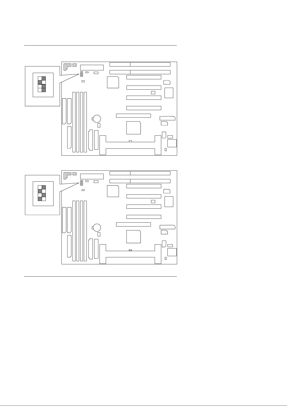
3. Pentium II 266 MHz
PIIX4
1
1
1
PIIX4
1
1
1
++ + +
4
3
2
ON OFF
SW
4. Pentium II 300 MHz
++ + +
Quick Installation Guide
1
GA-686BLX
1
11
1
1
1
82443LX
1
1
1
ON OFF
SW
4
3
2
1
GA-686BLX
1
11
1
1
1
82443LX
1
1
1
4
Page 7

GA-686BLX
PIIX4
1
1
1
PIIX4
1
1
1
5. Pentium II 333 MHz
++ + +
4
3
2
ON OFF
SW
6. Pentium II 366 MHz
++ + +
1
GA-686BLX
1
11
1
1
1
82443LX
1
1
1
ON OFF
SW
4
3
2
1
GA-686BLX
1
11
1
1
1
82443LX
1
1
1
5
Page 8

II. Jumper setting :
PIIX4
1111
1
+++
+
PIIX4
1
1
PWR : Power LED / Key-Lock Connector
1
++ + +
Quick Installation Guide
1
Pin No.
1
2
3
4
5
Function
LED anode (+)
NC
LED cathode (-)
Key Lock
GND
1
SPK : Speaker Connector
1
Pin No.
Function
1
VCC
2
NC
3
NC
4
Data
1
GA-686BLX
GA-686BLX
1
82443LX
82443LX
1
1
1
1
1
1
1
1
1
1
1
1
1
6
Page 9

GA-686BLX
PIIX4
11111
1
PIIX4
1
1
TD : Turbo LED Connector
++ + +
1
1
1
2
Function
LED anode (+)
LED cathode (-)
Pin No.
TB : Turbo Switch Connector
++ + +
Function Reserved
11
GA-686BLX
GA-686BLX
1
82443LX
82443LX
1
1
1
1
1
1
1
1
1
1
1
1
7
Page 10

RST : Reset Switch
PIIX4
1
1
Normal operation.
PIIX4
1
1
Open :
1
Normal operation.
Quick Installation Guide
++ + +
1
GA-686BLX
For Hardware
1
Reset
11
1
GN : Green Function Switch
++ + +
Open :
1
Close:
1
Enterning Green
11
1
GA-686BLX
1
82443LX
82443LX
1
1
1
1
1
1
1
1
1
1
1
1
8
Page 11

GA-686BLX
PIIX4
11111
1
PIIX4
1
1
HD : IDE Hard Disk Active LED
++ + +
Pin No.
1
2
1
Function
LED anode (+)
LED cathode (-)
Soft PWR : Soft Power Connector
1
++ + +
GA-686BLX
82443LX
1
1
1
1
1
1
Pin No. Function
1
GND
2 CTRL-Signal
1
GA-686BLX
1
11
1
1
1
82443LX
1
1
1
9
Page 12

POWER : Power Connector
PIIX4
1
1
12345
PIIX4
1
1
Quick Installation Guide
1
++ + +
Pin No. Function
1
Power Good
VCC (+5V)
2,10,11,12
+12V
3
-12V
4
5,6,7,8
GND
-5V9
J3 : Keyboard Connector
++ + +
1
GA-686BLX
1
11
1
1
1
82443LX
1
1
1
Pin No.
1
2
3
4
5
Function
Key Clock.
Key Data
NC
VCC (+5V)
GND
1
GA-686BLX
1
11
1
1
1
82443LX
1
1
1
10
Page 13
GA-686BLX
PIIX4
11111
1
PIIX4
1
1
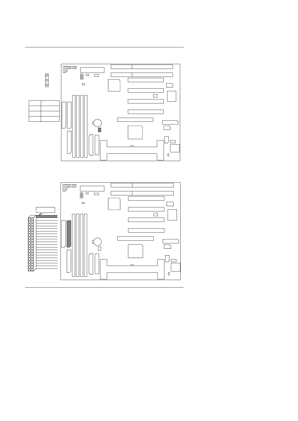
J2 : CPU Cooling Fan Power Connector
++ + +
1
1
Pin No.
Function
1
GND
2
+12V
SENSE
3
IDE1: For Primary IDE port
++ + +
RED LINE
1
11
GA-686BLX
GA-686BLX
1
82443LX
82443LX
1
1
1
1
1
1
1
1
1
1
1
1
11
Page 14

IDE2: For Secondary IDE port
PIIX4
1
1
PIIX4
1
1
++ + +
Quick Installation Guide
RED LINE
1
J5 : FLOPPY PORT
++ + +
RED LINE
1
1
GA-686BLX
1
11
1
1
1
82443LX
1
1
1
1
GA-686BLX
1
11
1
1
1
82443LX
1
1
1
12
Page 15
GA-686BLX
PIIX4
1
1
PIIX4
1
1
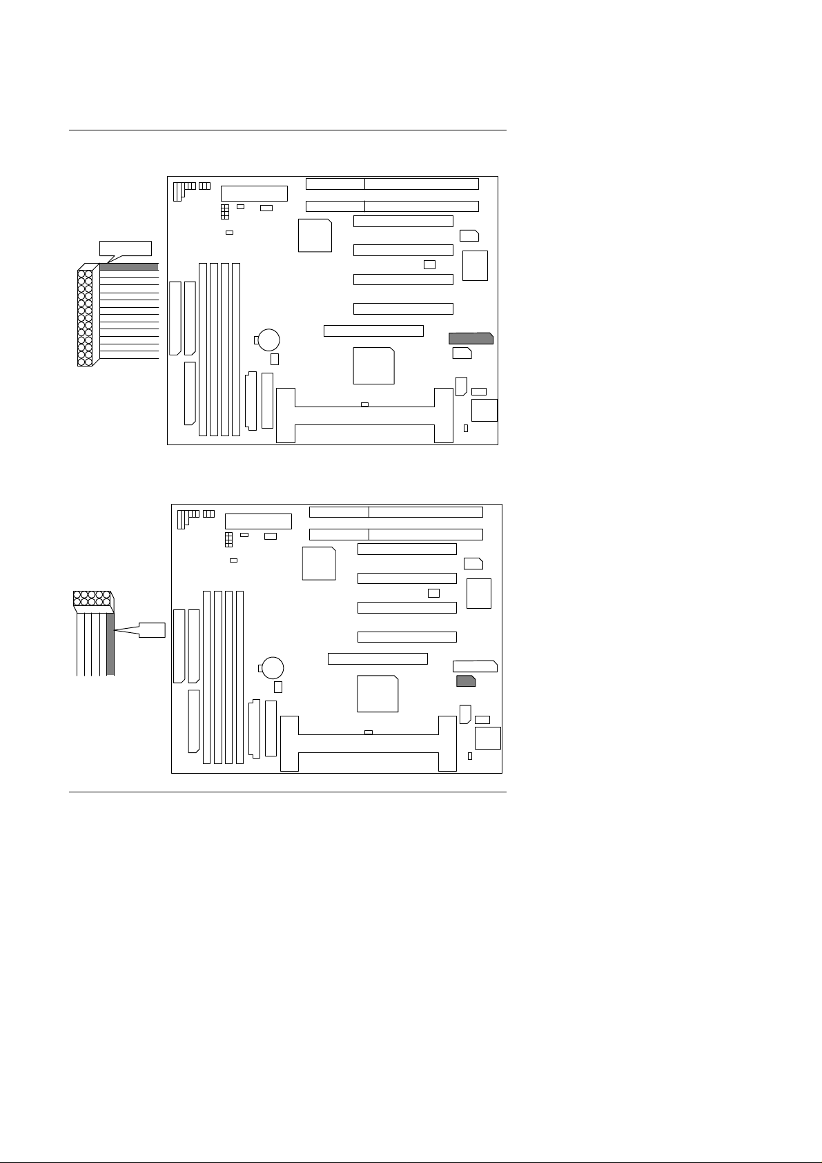
J8 : LPT PORT
++ + +
RED LINE
1
J6 : COM B
1
RED LINE
11
1
++ + +
GA-686BLX
1
GA-686BLX
82443LX
1
1
1
1
1
1
1
1
11
1
1
1
82443LX
1
1
1
13
Page 16

J7: COM A
PIIX4
Disable Keyboard Power On.
Enable Keyboard Power On.
PIIX4
1
1
RED LINE
Quick Installation Guide
++ + +
1
1
GA-686BLX
1
11
1
1
82443LX
1
1
1
1
1
JP6 : Keyboard Power On
++ + +
1
Open :
1
Close :
11
1
1
1
GA-686BLX
1
1
1
82443LX
1
1
1
14
Page 17

GA-686BLX
PIIX4
1
PIIX4
1
1
POWER1: ATX POWER Connector
++ + +
1
Pin No.
3,5,7,13,15-17
4,6,19,20
10
12
18
8
9
14
Function
GND
VCC (+5V)
+12V
-12V
-5V
Power Good
5V SB
(Stand by +5V)
PS-ON
(Soft ON/OFF)
J2 : PS/2 MOUSE
1
RED LINE
++ + +
11
GA-686BLX
1
11
1
1
1
1
82443LX
1
1
1
1
GA-686BLX
1
1
1
82443LX
1
1
1
1
15
Page 18

CN3: USB Port
PIIX4
11111
1
PIIX4
11111
1
Function
Pin No.
VCC
1
2
SBV 0-
3
SBV 0+
GND
4
VCC
5
SBV1-
6
7
SBV1+
8
GND
J9: Wake on Lan
++ + +
++ + +
GA-686BLX
Quick Installation Guide
1
1
82443LX
1
1
1
1
Pin No.
1
2
3
Function
+5V SB
GND
Signal
1
1
1
GA-686BLX
1
1
1
82443LX
1
1
16
Page 19

GA-686BLX
PIIX4
11111
1
1
PIIX4
11111
1
1
+++
+
J17: ACPI LED Selection
++ + +
1
Normal: short: 4 steps
open: 3 steps.
Function
Pin No.
Signal
1
2
GND
J10: System After Ac Back
GA-686BLX
82443LX
1
1
1
1
1
1
1
Normal:Open: Soft Off
Short: Full on/Soft Off
Function
Pin No.
Signal
1
2
GND
GA-686BLX
17
82443LX
1
1
1
1
1
1
Page 20

Quick Installation Guide
PIIX4
1111
1
+++
+
¡ô¡õ¡÷¡ö
J16: For PCI Audio / Sound Card use only
1
5
6
Pin No.
1
2
3
4
5
6
2
Function
Signal
GND
NC
Signal
GND
Signal
1
1
1
256
GA-686BLX
1
82443LX
1
III. Top Performance Test Setting:
Users have to modify the value for each item in chipset features as follow
for top performance setting.
ROM PCI / ISA BIOS
CHIPSET FEATURES SETUP
AWARD SOFTWARE, INC.
Auto Configuration
DRAM Speed Selection : Fast
Memory Buffer Strength : Middle
DRAM Data Integrity Mode
Video RAM Cacheable : Disabled
16 Bit I/O Recovery Time : 1
Memory Hole At 15M-16M : Disabled
Delayed Transaction : Disabled
SDRAM RAS-to-CAS Delay
SDRAM RAS Precharge Time
SDRAM CAS latency Time : 2
: Enabled
: Non-ECC
: Fast
: Fast
Power-Supply Type : Auto
CPU Temperature Select
: 70¢J/158
Slow Down CPU Duty Cycle : Normal
Alarm When Overheat : Disabled
Fan Failure Control : Disabled
CPU Fan Status : XXXX
CPU Temperature : OK
Power Supply +12V
Power Supply -12V
Power Supply +5V
Power Supply -5V
Battery Status
CPU VCore Voltage
: Quit
F1
: Help
F5
: Old Values
PU/PD/+/(Shift)F2
: OK
: OK
: OK
: OK
: OK
: 2.8V
: Select ItemESC
: Modify
: Color
F7 : Load Setup Defaults
¢K
1
1
1
18
 Loading...