

Atx MS-6380 User Manual

Introduction
Chapter 1.
Introduction
The K7T266 Pro (MS-6380) ATX mainboard is a high-performance
computer mainboard based on VIA® Apollo KT266 chipset and designed for
the AMD® Athlon or Duron (PGA) processor for inexpensive business/
personal desktop markets.
The Apollo KT266 chipset consists of the VT8366 Super Northbridge
and the VT8233 Southbridge. VT8366 provides a PC1600/2100 DDR (Double
Data Rate) solution with support for 200/266MHz Front Side Bus. By using
PC2100 DDR technology, the VT8366 enables 2.1GB/second peak bandwidth
between system memory and Northbridge. The chipset doubles the communication bandwidth between the North and South Bridge to 266MB/sec
through a high-speed V-Link bus. With AGP 4X interface, VT8366 boosts
system performance for 3D graphics and video program.
The VT8233 Southbridge integrates many peripheral controllers
including dual channel UltraDMA-33/66/100 master mode EIDE controller,
AC-link interface, LPC interface, USB controller etc. The VT8233 is compatible with PCI-2.2 specification and supports advanced power management.
The Apollo KT266 chipset provides the optimized performance for
the PC systems based on the latest AMD® processors.
This chapter includes the following topics:
Mainboard Specification 1-2
Mainboard Layout 1-4
Quick Components Guide 1-7
Key Features 1-8
MSI Special Features 1-9
1-1

Chapter 1
Mainboard Specification
CPU
! Support Socket A (Socket-462) for AMD® Athlon /Duron processor
! Support 600MHz up to 1.4GHz processor
Chipset
! VIA® VT8366 chipset (552 BGA)
- FSB @200/266MHz
- AGP 4X and PCI Advanced high performance memory controller
! VIA® VT8233 chipset (376 BGA)
- High Bandwidth V-link Client controller
- Integrated Faster Ethernet LPC (Optional CNR card support)
- Integrated Hardware Sound Blaster/Direct Sound AC97 audio
- Ultra DMA 33/66/100 master mode PCI EIDE controller
- ACPI
Clock Generator
! 100/133MHz clocks are supported
Main Memory
! Support six memory banks using three 184-pin DDR DIMMs
! Support a maximum memory size up to 3GB
! Support 2.5v DDR SDRAM DIMM
Slots
! One AGP (Accelerated Graphics Port) or AGP PRO slot
- AGP specification compliant
- Support AGP 2.0 1x/2x/4x
! One CNR (Communication Network Riser) slot
! Five 32-bit Master PCI Bus slots
! Supports 3.3V/5V PCI bus Interface
On-Board IDE
! An IDE controller on the VIA® VT8233 chipset provides IDE HDD/CD-
ROM with PIO, Bus Master and Ultra DMA 33/66/100 operation modes
! Can connect up to 4 IDE devices
Promise 20265R On-Board (Optional)
! Support IDE RAID 0 or 1
1-2

Introduction
! Can connect a Master and a Slave drive to each IDE RAID connector
! The two connectors support hard disk drives only
Note: Only the two Master hard disk drives will adopt RAID function.
USB Interface
! USB 2.0 HC On Board (for K7T266 Pro-RU only )
- Support 4 USB 2.0 ports via external bracket
! USB PC2PC Networking Function
- Controlled by USB PC2PC Controller
- Supported by the JUSB2 pin header
! 6 USB Ports (for K7T266 Pro & K7T266 Pro-R)
- Controlled by VT8233 Soughbirdge
- 2 rear ports and 4 ports supported by JUSB2 & JUSB3
Audio
! Chip integrated (2 channel S/W audio)
- Direct Sound AC97 Audio
On-Board Peripherals
! On-Board Peripherals include:
- 1 floppy port supports 2 FDD with 360K, 720K, 1.2M, 1.44M and
2.88Mbytes
- 2 serial ports (COMA + COMB)
- 1 parallel port supporting SPP/EPP/ECP mode
- 1 IrDA connector for SIR/ASKIR/HPSIR
- 1 Audio/Game port
BIOS
! The mainboard BIOS provides Plug & Play BIOS which detects the
peripheral devices and expansion cards of the board automatically
! The mainboard provides a Desktop Management Interface (DMI) func-
tion which records your mainboard specifications
Dimension
! ATX Form Factor (30.4 cm X 23.5 cm)
Mounting
! 6 mounting holes
1-3
Chapter 1
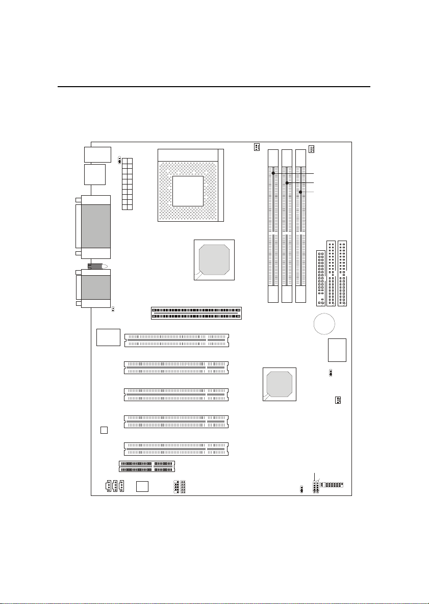
Mainboard Layout
MS-6380 provides three types of models to meet consumers
diverse needs: K7T266 Pro, K7T266 Pro-R and K7T266 Pro-RU.
Top: Mouse
Bottom:
Keyboard
USB Ports
Top: Parallel
Port
Bottom:
COM A &
COM B
Diagnostic LED
Top : Ga me
Port
Bottom:
Audio Ports
W83627HF -AW
Winbond
JKBV1
Socket 462
y
l
p
p
u
S
r
e
w
o
P
X
T
A
81)
86&!$$
J8
AGP Slot
PCI Slot 1
PCI Slot 2
PCI Slot 3
CFAN1
81)
86& !!
PSFAN1
,,4
,,4
,,4!
,
,
.
BATT
+
JBAT1
,
1
BIOS
,
1
JMDM
Codec
PCI Slot 4
SFAN1
PCI Slot 5
X
U
PC2PC
A
J
Controller
JCD
CNR Slot
JUSB2
JUSB3
JGL1
JMDM1
J6
JFP1
MS-6380 ATX Mainboard
(K7T266 Pro)
1-4
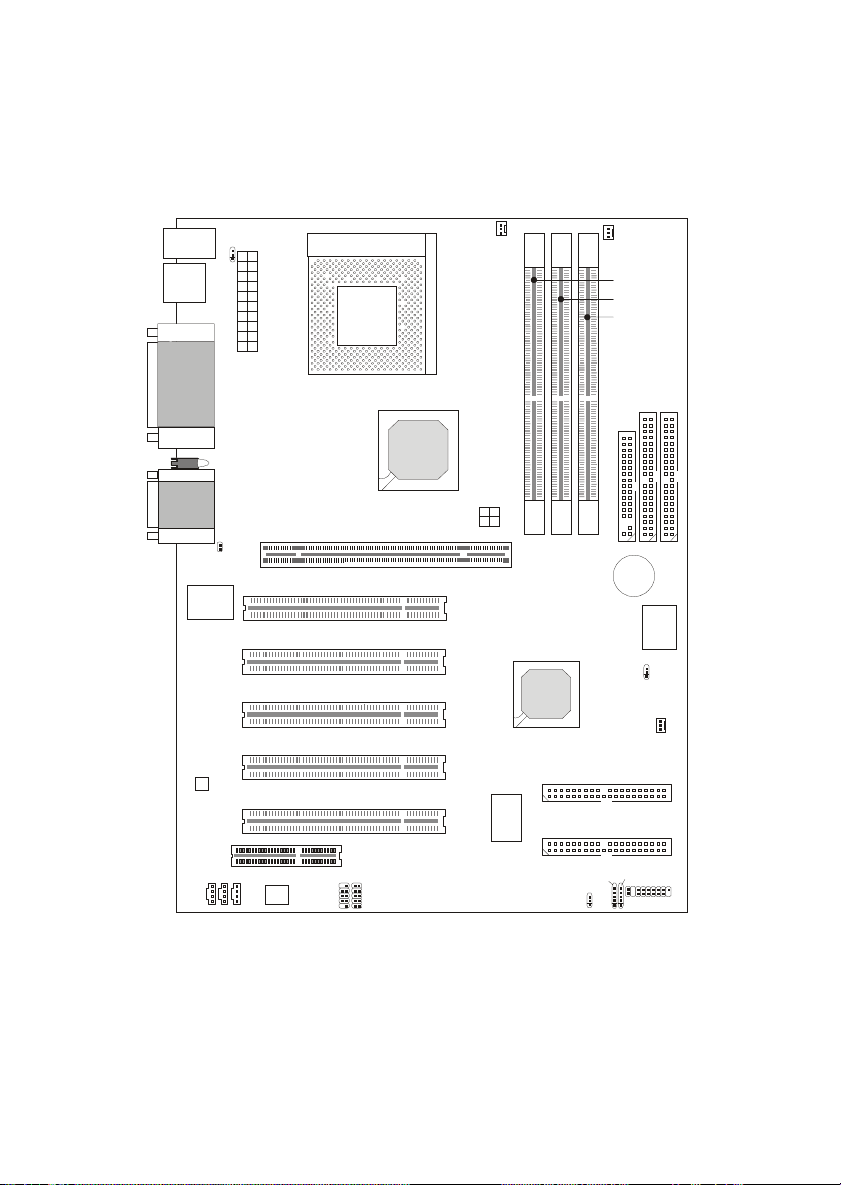
Top: Mouse
Bottom:
Keyboard
USB Ports
Top: Parallel
Port
Bottom:
COM A &
COM B
Diagnostic LED
Top : Ga me
Port
Bottom:
Audio Ports
W83627HF -AW
Winbond
JKBV1
Introduction
Socket 462
y
l
p
p
u
S
r
e
w
o
P
X
T
A
81)
86&!$$
J8
AGP Pro Slot
CFAN1
JWR1
PCI Slot 1
PCI Slot 2
PCI Slot 3
81)
86& !!
PSFAN1
,,4
,,4
,,4!
,
,
.
BATT
+
JBAT1
,
1
BIOS
,
1
JMDM
Codec
PCI Slot 4
SFAN1
IDE4
PCI Slot 5
X
U
PC2PC
A
J
Controller
JCD
CNR Slot
JUSB2
JUSB3
P
2
R
0
O
2
M
6
5
I
S
R
E
JGL1
IDE3
JMDM1
J6
JFP1
MS-6380 ATX Mainboard
(K7T266 Pro-R)
1-5
Chapter 1
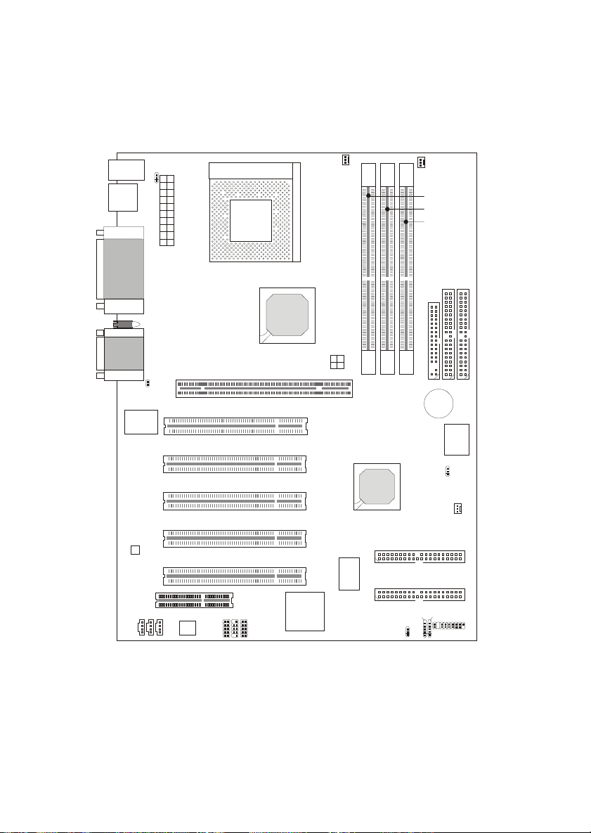
Top: Mouse
Bottom:
Keyboard
USB Ports
Top: Parallel
Port
Bottom:
COM A &
COM B
Diagnostic LED
Top : Ga me
Port
Bottom:
Audio Ports
W83627 HF-AW
Winbond
JKBV1
Socket 462
y
l
p
p
u
S
r
e
w
o
P
X
T
A
81)
86&!$$
J8
AGP Pro Slot
CFAN1
JWR1
PCI Slot 1
PCI Slot 2
PCI Slot 3
81)
86& !!
PSFAN1
,,4
,,4
,,4!
,
,
.
BATT
+
JBAT1
,
1
BIOS
,
1
JMDM
Codec
PCI Slot 4
SFAN1
IDE4
PCI Slot 5
JUSB3
NEC
USB 2.0
Host
Controller
X
U
PC2PC
A
J
Controller
JCD
CNR Slot
JUSB2
JUSB1
P
2
R
0
O
2
M
6
5
I
S
R
E
JGL1
IDE3
JMDM1
J6
JFP1
MS-6380 ATX Mainboard
(K7T266 Pro-RU)
1-6

Introduction
Quick Components Guide
Component Function Reference
DDR1~3 Installing DDR SDRAM modules See p. 2-5~2-6
Socket 462 Installing CPU See p. 2-2~2-4
CFAN1 Connecting to CPUFAN See p. 2-20
SFAN1 Connecting to SYSTEM FAN See p. 2-20
PSFAN1 Connecting to Power Supply FAN See p. 2-20
ATX Power Supply Installing power supply See p. 2-7
IDE1& IDE2 Connecting to IDE hard disk drive See p.2-13
IDE3& IDE4 Connecting to IDE RAID HDD See p.2-14
FDD1 Connecting to floppy disk drive See p.2-12
JUSB1~3 Connecting to USB interfaces See p. 2-22~2-26
PCI Slot 1~5 Installing expansion cards See p. 2-30
AGP/AGP PRO Slot Installing AGP (Pro) cards See p. 2-30
CNR Slot Installing expansion cards See p. 2-30
JMDM1 Connecting to modem module See p. 2-18
JBAT1 Clearing CMOS data See p. 2-28
JFP1 Connecting to case See p. 2-15
JGL1 Connecting to power saving LED See p. 2-17
J6 Connecting to IR module See p. 2-19
J8 Connecting to chassis intrusion switch See p. 2-18
JWR1 Connecting to AGP Pro cards power cable See p. 2-27
JKBV1 Enabling Keyboard wake up function See p. 2-29
1-7

Chapter 1
Key Features
! ATX Form Factor
! CPU: Socket A for AMD
®
Duron/Athlon Processor
! Memory: 3 PC1600/PC2100 DDR DIMMs
! Slot: 1 AGP/AGP PRO slot, 1 CNR slot, 5 PCI slots
! I/O: 2 serial ports. 1 parallel port, 6 USB 1.1 ports, 1 floppy port, 1 IrDA
connector, 3 Audio/1 Game port (for K7T266 Pro & K7T266 Pro-R)
! I/O: 2 serial ports. 1 parallel port, 4 USB 1.1 & 4 USB 2.0 ports, 1 floppy
port, 1 IrDA connector, 3 Audio/1 Game port ( for K7T266 Pro-RU)
! USB Interface: USB 1.1 PC to PC Networking & USB 2.0 HC On-Board
(Optional)
! 2 IDE RAID connectors (Optional)
! Fuzzy Logic III overclocking utility
! D-LED -- 4 LEDs embedded in the mainboard
! PC Alert III system hardware monitor
! Audio: 2 Channel S/W audio integrated
! PCI 2.2 LAN Wake up Function
! Modem (External/Internal) Ring Wake up Function
1-8
Introduction
MSI Special Features
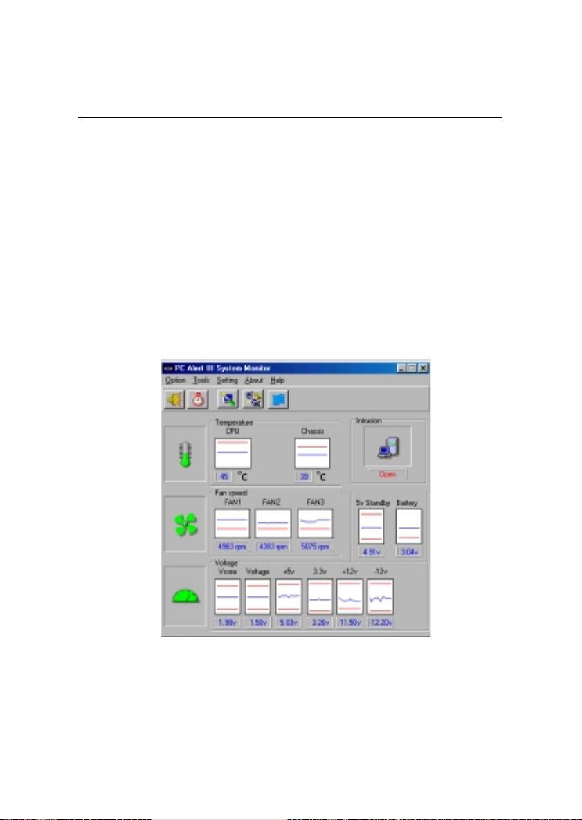
PC Alert III
The PC AlertTM III is an utility you can find in the CD-ROM disk. The
utility is just like your PC doctor that can detect the following PC hardware
status during real time operation:
* monitor CPU & system temperatures
* monitor fan speed(s)
* monitor system voltage
* monitor chassis intrusion
If one of the items above is abnormal, the program main screen will be immediately shown on the screen, with the abnormal item highlighted in red. This will
continue to be shown,until user disables the warning.
Note: Items shown on PC Alert III vary depending on your systems status.
1-9

Chapter 1
Features:
! Network Management
- Monitoring & remote control
! Basic System Utilities
- Scandisk & Defragment to maintain your HDD
! 3D Graphics Design
- Enables a more friendly user interface
! Sofware Utilities
- SoftCooler Optimized Cooling
1-10
Introduction
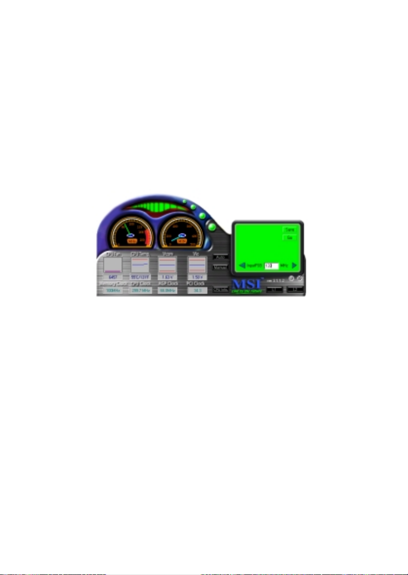
Fuzzy Logic III
The Fuzzy Logic III utility allows users to overclock the CPU FSB
(Front Side Bus) frequency in the Windows environment. Select the CPU
frequency you prefer and click Go to apply the frequency or click Save
allowing the system to run at the specified frequency each time when the
system is powered on.
Features:
! Display Current System Status
- CPU Fan
- CPU Temp.
- Vcore
- Vio
- Memory Clock
- CPU Clock
- AGP Clock
- PCI Clock
! Adjust CPU FSB Frequency
1-11
Chapter 1
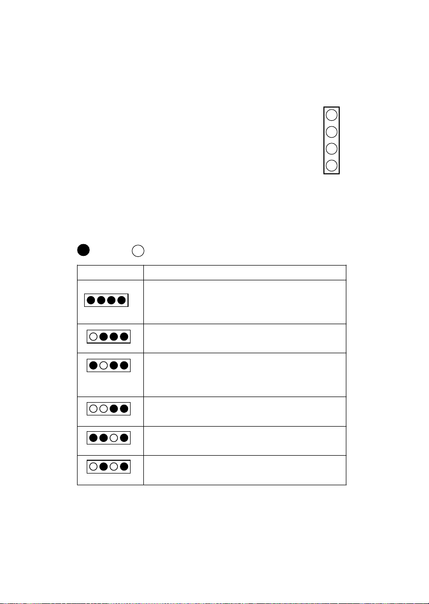
D-LED
The D-LED uses graphic signal display to help
users understand their system. Four LEDs embedded in
the mainboard provide up to 16 combinations of signals to
debug the system. The 4 LEDs can debug all problems that
fail the system, such as VGA, RAM or other failures. This
special feature is very useful for the overclocking users.
These users can use the feature to detect if there are any
problems or failures.
Red
D-LED Description
1 2 3 4
Green
System Power ON
- The D-LED will hang here if the processor is damaged or not
installed properly.
Early Chipset Initialization
Memory Detection Test
- Testing onboard memory size. The D-LED will hang if the
memory module is damaged or not installed properly.
Decompressing BIOS image to RAM for fast booting.
Initializing Keyboard Controller.
Testing VGA BIOS
- This will start writing VGA sign-on message to the screen.
1
2
3
4
Diagnostic LED
1-12

Introduction
Processor Initialization
- This will show information regarding the processor (like brand
name, system bus, etc)
Testing RTC (Real Time Clock)
Initializing Video Interface
- This will start detecting CPU clock, checking type of video
onboard. Then, detect and initialize the video adapter.
BIOS Sign On
- This will start showing information about logo, processor
brand name, etc.
Testing Base and Extended Memory
- Testing base memory from 240K to 640K and extended
memory above 1MB using various patterns.
Assign Resources to all ISA.
Initializing Hard Drive Controller
- This will initialize IDE drive and controller.
Initializing Floppy Drive Controller
- This will initializing Floppy Drive and controller.
Boot Attempt
- This will set low stack and boot via INT 19h.
Operating System Booting
1-13

Chapter 2.
Hardware Setup
Hardware Setup
This chapter provides you with the information about hardware setup
procedures. While doing the installation, be careful in holding the components and follow the installation procedures. For some components, if you
install in the wrong orientation, the components will not work properly.
Use a grounded wrist strap before handling computer components.
Static electricity may damage the components.
This chapter contains the following topics:
Central Processing Unit (CPU) 2-2
Memory 2-5
Power Supply 2-7
Back Panel 2-8
Connectors 2-12
Jumpers 2-28
Slots 2-30
2-1
Chapter 2
Central Processing Unit: CPU
The mainboard supports AMD® AthlonTM and DuronTM processor.
The mainboard uses a CPU socket called Socket A for easy CPU installation.
Make sure the CPU has a Heat Sink and a cooling fan attached on the top to
prevent overheating. If you do not find the Heat Sink and cooling fan,
contact your dealer to purchase and install them before turning on the
computer.
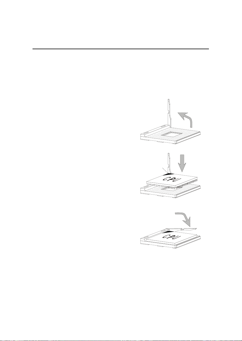
CPU Installation Procedures
1. Pull the lever sideways away
from the socket. Then, raise
the lever up to a 90-degree
angle.
2. Look for the cut edge. The
cut edge should point
towards the lever pivot. The
CPU will only fit in the
correct orientation.
3. Hold the CPU firmly, and
then press the lever down to
complete the installation.
Open Lever
Sliding
Plate
Cut edge
Close
Lever
2-2

Hardware Setup
Thermal Issue for CPU
!
WARNING!
thermal environment is key to reliable operation. As such, the processor must
be maintained in the specified thermal requirements. AMD recommends the
use of high performance thermal interface material.
AMD Athlon/Duron processor with a speed of 600MHz and above requires LARGER heatsink and fan. You also need to add thermal grease between the CPU and heatsink to improve heat dissipation. Then, make sure that
the CPU and heatsink are securely fastened and in good contact with each
other. These are needed to prevent damaging the processor and ensuring
reliable operation.
You can check AMDs web site for more information on proper cooling: http:/
/www.amd.com/products/cpg/athlon/pdf/cooling_guide.pdf
As processor technology pushes to faster speeds and higher
performance, thermal management becomes increasingly crucial when building computer systems. Maintaining the proper
2-3
Chapter 2
CPU Core Speed Derivation Procedure
If CPU Clock = 100MHz
Core/Bus ratio = 7
then CPU core speed = Host Clock x Core/Bus ratio
= 100MHz x 7
= 700MHz
CPU Clock Frequency Selection through BIOS
To set the clock frequency of the CPU installed on the motherboard,
refer to Hardware Monitor Setup of BIOS on page 3-26.
The default hardware configuration for CPU Clock Frequency is 100MHz.
Therefore, to use a 133MHz CPU, you need to adjust the CPU clock up to
133MHz by changing the CPU clock in the BIOS Setup utility.
While replacing the CPU, always turn off the ATX
!
WARNING!
power supply or unplug the power cable of the ATX
power supply from grounded outlet first to ensure the
safety of CPU.
2-4
Hardware Setup
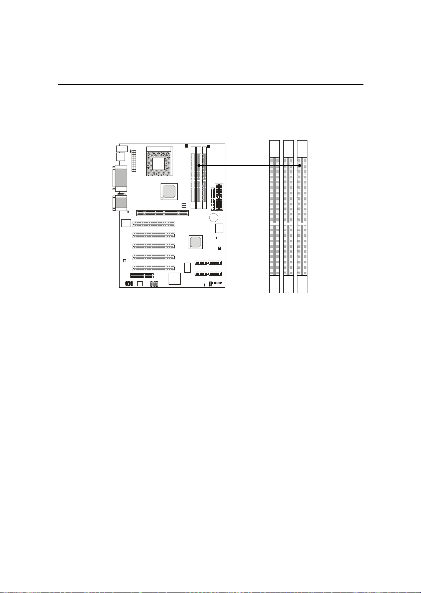
Memory
The mainboard provides 3 sockets for 184-pin, 2.5V DDR DIMM with 6
memory banks. To operate properly, at least one DIMM module must be
installed.
DDR DIMM Slots
(DDR 1~3)
You can install PC1600/PC2100 DDR SDRAM modules on the DDR
DIMM slots (DIMM 1~3).
DDR (Double Data Rate) SDRAM is similar to conventional SDRAM,
but doubles the rate by transfering data twice per cycle. It transfers data on
both the rising and falling edges of the clock. Conventional SDRAM only
uses the rising edge of the clock to transfer data. Therefore, conventional
SDRAM is called SDR (Single Data Rate) SDRAM.
DDR SDRAM uses 2.5 volts as opposed to 3.3 volts used in SDR
SDRAM, and requires 184-pin DIMM modules rather than 168-pin DIMM
modules used by SDR SDRAM. DDR SDRAM is also known as SDRAM-II,
DDR DRAM and DSDRAM (Double-Speed DRAM).
Two types of DDR are available at the time of writing: PC1600 & PC2100.
PC1600 DDR SDRAM running at 100MHz will produce about 1.6GB/s memory
bandwidth. PC2100 running at 133MHz will produce 2.1GB/s memory
bandwidth. High memory bandwidth makes DDR an ideal solution for high
performance PC, workstations and servers.
2-5
Chapter 2
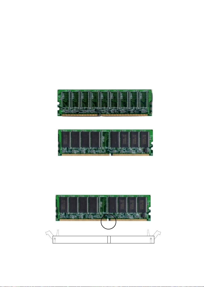
DDR Module Installation
You can install either single sided or double sided 184-pin DDR DIMM
modules into DDR DIMM slots to meet your needs. Different from the SDR
DIMM, the DDR DIMM has only one notch on the center of module. The
number of pins on either side of the breaks are different. The module will only
fit in the right orientation.
Single Sided DIMM
Double Sided DIMM
1. Insert the DIMM module vertically into the DDR DIMM slot. Make sure the
notch is on the right orientation.
2. The plastic clips at sides of the DIMM slot will automatically close.
Vol t
2-6
Hardware Setup
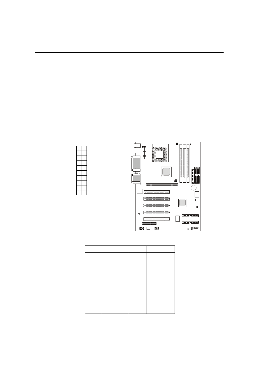
Power Supply
The mainboard supports ATX power supply for the power system.
Before inserting the power supply connector, always make sure that all components are installed properly to ensure that no damage will be caused.
ATX 20-Pin Power Supply
This connector allows you to connect to an ATX power supply. To
connect to the ATX power supply, make sure the plugs of the power supply is
inserted in the proper orientation and the pins are aligned. Then push down
the power supply firmly into the connector.
11
1
20
10
ATX
Power Connector
PIN SIGNAL
1 3.3V
2 3.3V
3 GND
45V
5 GND
65V
7 GND
8 PW_OK
9 5V_SB
10 12V
PIN SIGNAL
11 3.3V
12 -12V
13 GND
14 PS_ON
15 GND
16 GND
17 GND
18 -5V
19 5V
20 5V
2-7

Chapter 2
Back Panel
The Back Panel provides the following connectors:
Mouse
Keyboard USB
Parallel
COM A COM B L-out L-in
Midi/Joystick
MIC
Mouse Connector
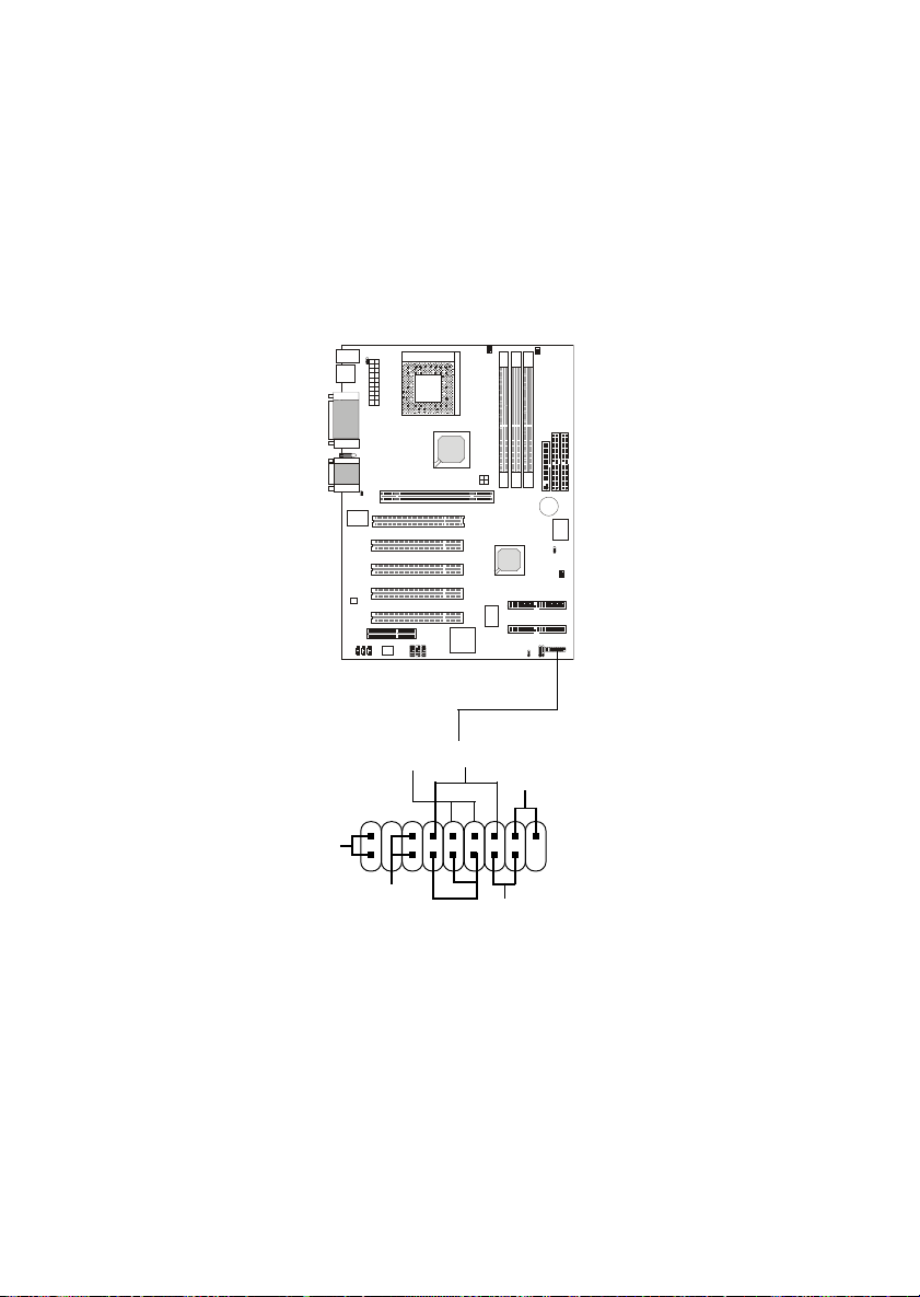
The mainboard provides a standard PS/2® mouse mini DIN connector
for attaching a PS/2® mouse. You can plug a PS/2® mouse directly into this
connector.
Pin Definition
6
4
2
PS/2 Mouse (6-pin Female)
5
3
1
PIN SIGNAL DESCRIPTION
1 Mouse DATA Mouse DATA
2 NC No connection
3 GND Ground
4 VCC +5V
5 Mouse Clock Mouse clock
6 NC No connection
2-8
Hardware Setup
Keyboard Connector
The mainboard provides a standard PS/2® keyboard mini DIN connector for attaching a PS/2® keyboard. You can plug a PS/2® keyboard directly into
this connector.
Pin Definition
PIN SIGNAL DESCRIPTION
6
21
PS/2 Keyboard (6-pin Female)
5
34
1 Keyboard DATA Keyboard DATA
2 NC No connection
3 GND Ground
4 VCC +5V
5 Keyboard Clock Keyboard clock
6 NC No connection
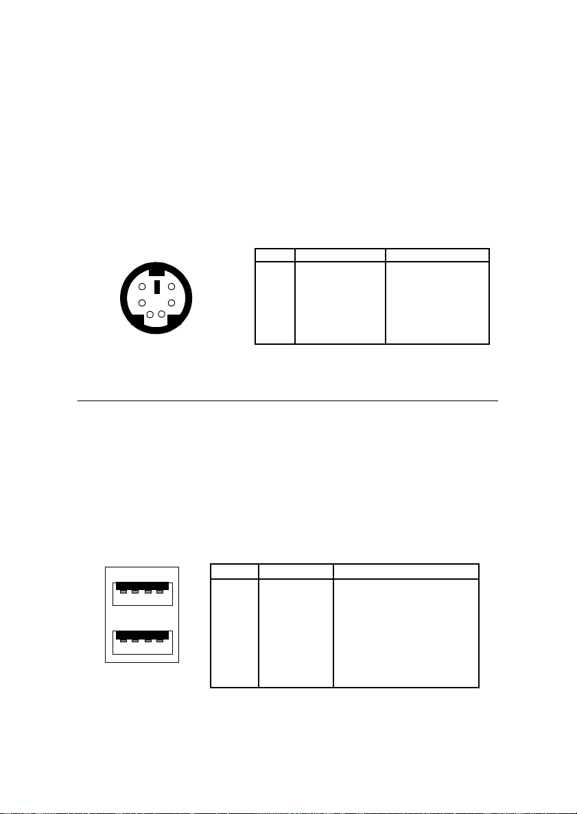
USB Connectors
The mainboard provides a UHCI (Universal Host Controller Interface)
Universal Serial Bus root for attaching USB devices such as keyboard, mouse
or other USB-compatible devices. You can plug the USB device directly into
ths connector.
1 2 3 4
5 6 7 8
USB Ports
USB Port Description
PIN SIGNAL DESCRIPTION
1 VCC +5V
2 -Data 0 Negative Data Channel 0
3 +Data0 Positive Data Channel 0
4 GND Ground
5 VCC +5V
6 +Data 1 Positive Data Channel 1
7 -Data 1 Negative Data Channel 1
8 GND Ground
2-9
Chapter 2
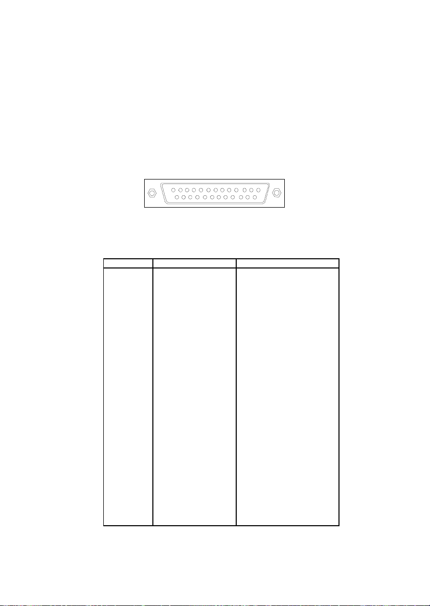
Parallel Port Connector
The mainboard provides a 25-pin female centronic connector for LPT.
A parallel port is a standard printer port that supports Enhanced Parallel Port
(EPP) and Extended Capabilities Parallel Port (ECP) mode.
13
1
1425
Pin Definition
PIN SIGNAL DESCRIPTION
1 STROBE Strobe
2 DATA0 Data0
3 DATA1 Data1
4 DATA2 Data2
5 DATA3 Data3
6 DATA4 Data4
7 DATA5 Data5
8 DATA6 Data6
9 DATA7 Data7
10 ACK# Acknowledge
11 BUSY Busy
12 PE Paper End
13 SELECT Se lect
14 AUTO FEED# Automatic Feed
15 ERR# Error
16 INIT# Initialize Printer
17 SLIN# Select In
18 GND Ground
19 GND Ground
20 GND Ground
21 GND Ground
22 GND Ground
23 GND Ground
24 GND Ground
25 GND Ground1
2-10
Hardware Setup
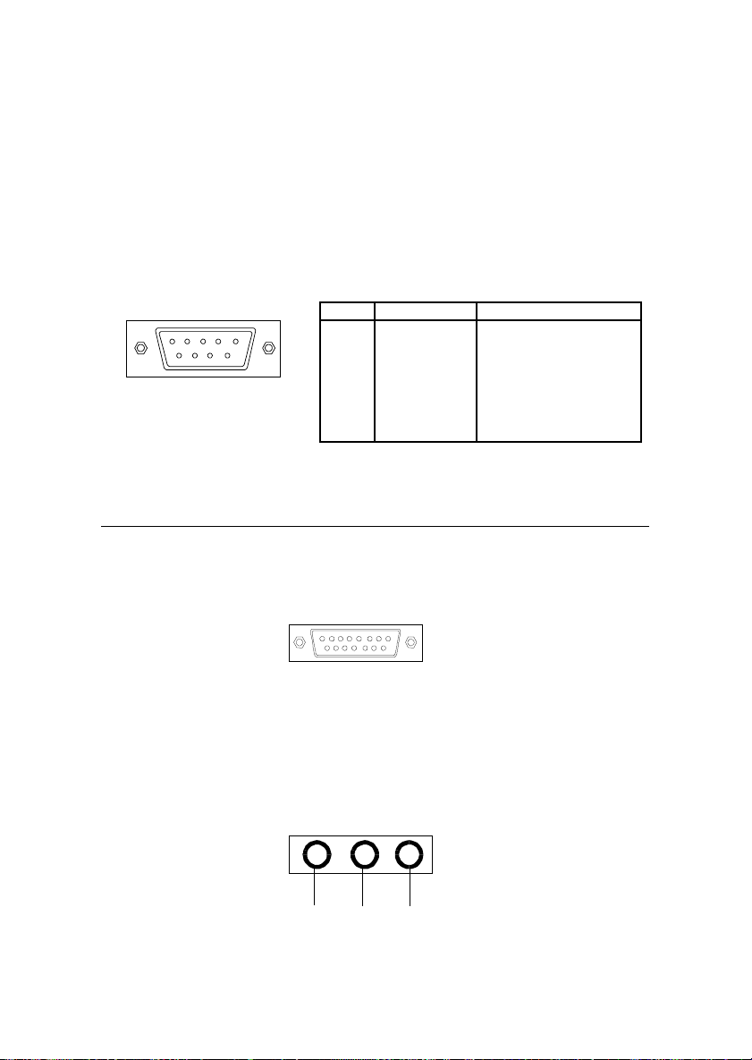
Serial Port Connector: COM A & COM B
The mainboard has two 9-pin male DIN connectors for serial port COM
A and COM B. You can attach a serial mouse or other serial devices.
Pin Definition
1 2 3 4 5
6 7 8 9
9-Pin Male DIN Connectors
PIN SIGNAL DESCRIPTION
1 DC D Data Carry Detect
2 SIN Serial In or Receive Data
3 SOUT Serial Out or Transmit Data
4 DT R Data Terminal Ready)
5 G ND Ground
6 DS R Data Set Ready
7 RT S Request To Send
8 CTS Clear To Send
9 RI Ring Indicate
Joystick/Midi Connectors
You can connect a joystick or game pad to this connector.
Audio Port Connectors
Line Out is to connect speakers or headphones. Line In is a connector
for external CD player, Tape player or other audio devices. Mic is used to
connect to a microphone.
Line Out
Line In MIC
2-11
Chapter 2
Connectors
The mainboard provides connectors to connect to FDD, IDE HDD,
case, modem, LAN, USB Ports, IR module and CPU/Power supply/System
FAN.
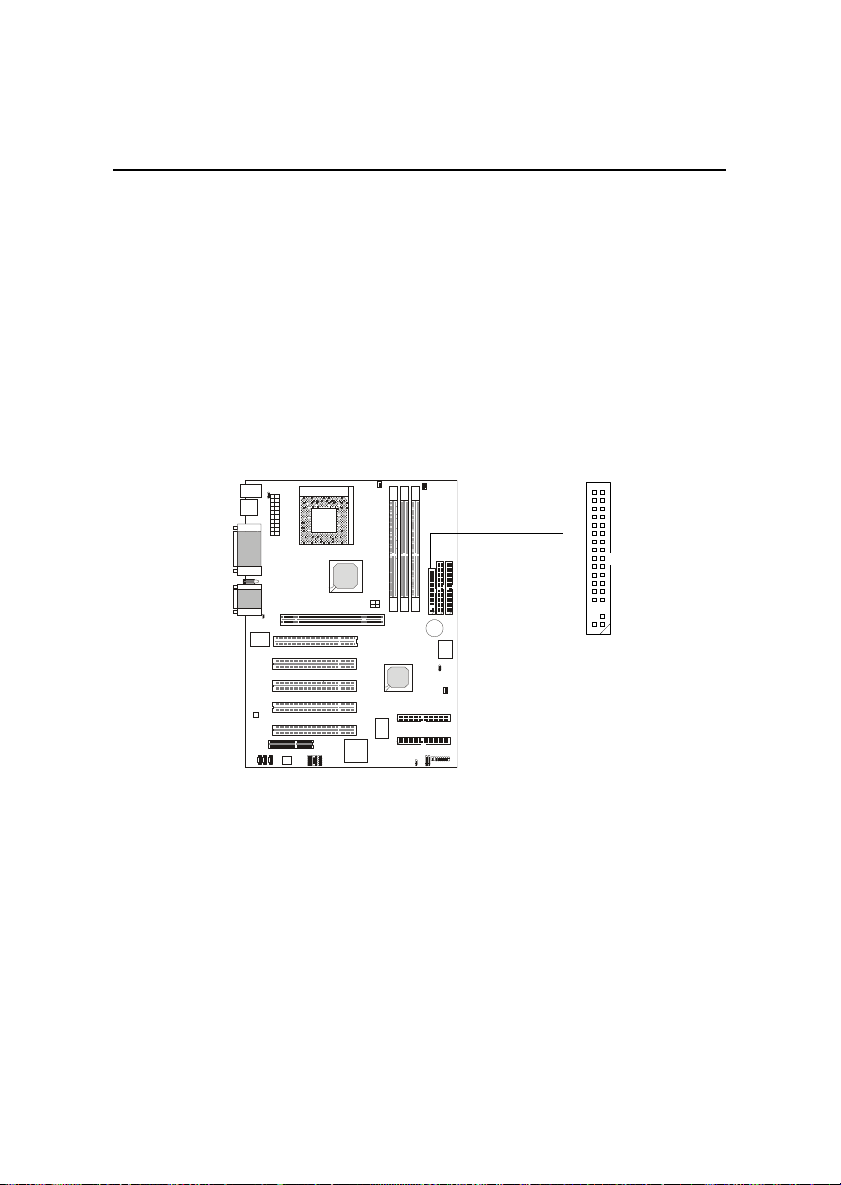
Floppy Disk Drive Connector: FDD1
The mainboard provides a standard floppy disk drive connector that
supports 360K, 720K, 1.2M, 1.44M and 2.88M floppy disk types.
34
33
12
FDD1
2-12
Hardware Setup
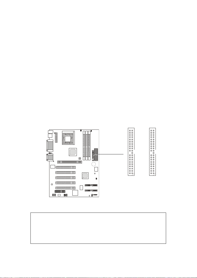
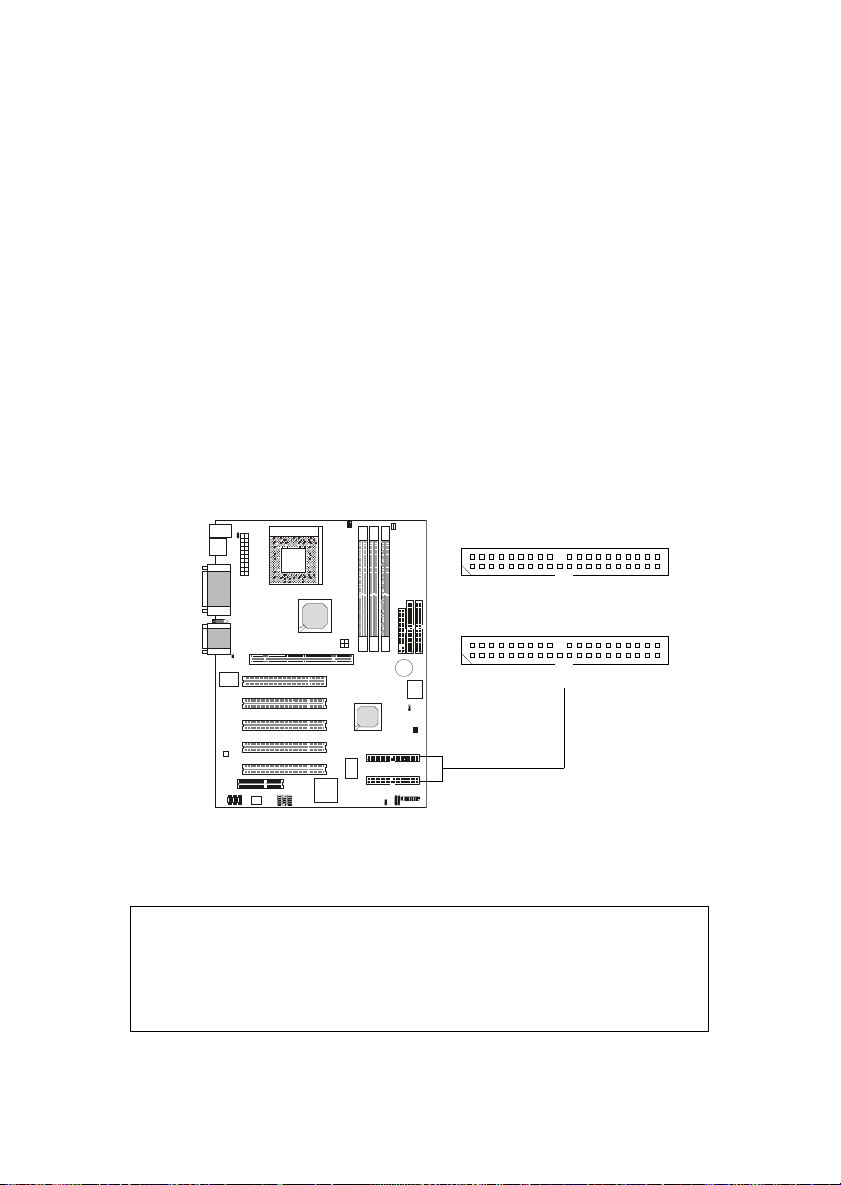
Hard Disk Connectors: IDE1 & IDE2
The mainboard uses an IDE controller on the VIA® VT8233 chipset that
provides PIO mode 0-4, Bus Master, and Ultra DMA 33/66/100 modes. It has
two HDD connectors IDE1 (Primary) and IDE2 (Secondary). You can connect
up to four hard disk drives, CD-ROM or 120MB Floppy to IDE1 and IDE2.
IDE1 (Primary IDE Connector)
- The first hard disk drive should always be connected to IDE1. You can
connect a Master and a Slave drive to IDE1.
IDE2 (Secondary IDE Connector)
- You can connect a Master and a Slave drive to IDE2.
40 39
2
11
40 39
Primary IDE Connector
2
!TIP:
If you install two hard disks on cable, you must configure the second
drive to Slave mode by setting its jumper. Refer to the hard disk documentation supplied by hard disk vendors for jumper setting instructions.
Secondary IDE Connector
2-13
Chapter 2
IDE RAID Connectors: IDE3 & IDE4 (Optional)
The mainboard offers a low-cost RAID (Redundant Array of Independent Disks) solution by integrating two IDE RAID connectors that support
PIO mode 0-4, Bus Master, and Ultra DMA 33/66/100 modes. The IDE RAID
connectors allow you to connect Ultra ATA/DMA hard disks and use RAID
technology for high performance, data security and fault tolerance. The connectors support RAID 0 (striping) and RAID 1 (mirroring).
IDE RAID Connectors
- You can connect a Master and a Slave drive to each IDE RAID connector.
- For more information on IDE RAID, please refer to IDE RAID Manual.
2
1
IDE4
2
1
IDE3
40
39
40
39
!TIP:
If you install two hard disks on cable, you must configure the second
drive to Slave mode by setting its jumper. Refer to the hard disk documentation supplied by hard disk vendors for jumper setting instructions.
2-14
Hardware Setup
Case Connector: JFP1
The case connector block JFP1 allows you to connect to the Power
Switch, Reset Swtich, Keylock, Speaker, Power LED, and HDD LED on the
case.
Keylock
Buzzer
(short pin)
+
HDD
LED
Speaker
14
Power
LED
JFP1
2-15
15
+
Reset
Switch
Power
Switch

Chapter 2
Power Switch
Connect to a 2-pin push button switch.
Reset Switch
Reset switch is used to reboot the system rather than turning the power ON/
OFF. Avoid rebooting while the HDD is working. You can connect the
Reset switch from the system case to this pin.
Power LED
The Power LED is lit while the system power is on.
Speaker
Speaker from the system case is connected to this pin.
If on-board Buzzer is available, then:
Always short pin 14-15 to enable on-board Buzzer
HDD LED
HDD LED shows the activity of a hard disk drive connected to the IDE1 or
IDE2 connector. Avoid turning the power off while the HDD is working.
You can connect the HDD LED from the system case to this pin.
Keylock
Keylock allows you to disable the keyboard for security purpose. You can
connect the keylock to this pin.
2-16
Hardware Setup
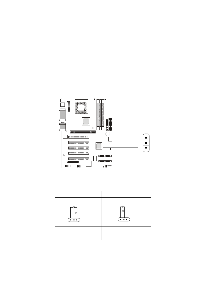
Power Saving LED Connector: JGL1
JGL1 is connected to a power saving LED. There are two types of LED
that you can use: 3-pin or 2-pin (ACPI request) LED. If connected to a 2-pin
LED, the LED light is green when system in turned on, and turns to orange
color while entering the sleep state. For 3-pin LED, the LED is lit when system
is on, and blinks during the sleep state.
1
JGL1
3-Pin LED 2-Pin LED
Green Color
!
Orange Color
Green Color
Orange Color
!
1-2 Single Color 1-2 Dual Color
1-3 Blink
2-17
 Loading...