

ATX MB-i965Q User Manual

MB-i965Q
ATX Industrial Motherboard
User’s Manual
Version 1.0
2008.02

- i -
Index
Table of Contents
Chapter 1 - Introduction ............................................ 1
1.1 Copyright Notice ...................................................2
1.2 About this User’s Manual .....................................2
1.3 Warning..................................................................2
1.4 Replacing the lithium battery ..............................3
1.5 Technical Support .................................................3
1.6 Warranty ................................................................4
1.7 Packing List ...........................................................5
1.8 Ordering Information ............................................5
1.9 Specication .........................................................6
1.10 Board Dimensions ..............................................7
1.11 Installing the CPU ...............................................8
1.12 Installing the Memory .........................................9
Chapter 2 - Installation ............................................ 11
2.1 Block Diagram .....................................................12
2.2 Jumpers and Connectors ..................................13
Jumpers ......................................................................14
JP3: PATA IDE Select ............................................14
JBAT1: CMOS Setup .............................................14
JRS1: COM2 RS-232/422/485 Mode Select ..........15
JP2: AT/ATX Power Mode Select ..........................16
JP1: BIOS Write Protect ........................................16
Connectors .................................................................17
SATA1 ~4: Serial ATA Connectors ........................17
IDE1: Primary IDE Connector ...............................18
TPM1: Trusted Platform Module Connector ........19
USB1 ~3: USB Connectors ...................................19
JFRT1: Switches and Indicators ..........................20
COM2: RS-232/422/485 Connector .......................21
FDD1: FDD Connector ...........................................21
DIO1: Digital I/O Connector ..................................22
CDIN1: Audio CD IN Connector ............................22

- ii -
Index
LOUT1: Audio Line Out Connector ......................22
ATX1: ATX Power Supply Connector ...................23
ATX12V1: ATX +12V Connector ............................23
EKB1: External Keyboard/ Mouse Connector.....24
SYSF1/SYSF2: System Fan Power Connectors..24
CPUF1: CPU Fan Power Connector .....................24
Audio1/ Audio2: HD Audio Phone Jacks .............25
LAN1/LAN2: RJ-45 & double stack USB
Connectors.......................................25
VGA1: CRT Connector ..........................................26
COM1: RS-232 Connector .....................................26
LPT1: Parallel Port Connector..............................27
KBM1: PS/2 Keyboard & Mouse Connectors ......27
2.3 The Installation Paths of CD Driver ...................28
Chapter 3 - BIOS ...................................................... 29
3.1 BIOS Main Setup .................................................30
3.2 Advanced Settings..............................................31
CPU Conguration ................................................32
IDE Conguration ..................................................33
Floppy Conguration ............................................34
Super IO Conguration .........................................35
Hardware Health Conguration ............................37
ACPI Conguration ...............................................38
APM Conguration ................................................39
MPS Conguration ................................................41
Remote Access Conguration .............................42
Trusted Computing ................................................44
USB Conguration ................................................45
3.3 Advanced PCI/PnP Settings ..............................47
3.4 Boot Settings ......................................................49
Boot Settings Conguration .................................50
3.5 Security ................................................................51

- iii -
3.6 Advanced Chipset Settings ...............................53
North Bridge Chipset Conguration ....................53
South Bridge Chipset Conguration ...................54
3.7 Exit Options .........................................................56
3.8 Beep Sound codes list .......................................61
Boot Block Beep codes ........................................61
POST BIOS Beep codes ........................................61
Troubleshooting POST BIOS Beep codes ...........62
3.9 AMI BIOS Checkpoints .......................................63
Bootblock Initialization Code Checkpoints .........63
Bootblock Recovery Code Checkpoints .............65
POST Code Checkpoints ......................................67
DIM Code Checkpoints .........................................71
ACPI Runtime Checkpoints ..................................73
Chapter 4 - Appendix ..............................................75
4.1 I/O Port Address Map .........................................76
4.2 Interrupt Request Lines (IRQ) ............................77
Index

- iv -
This page is intentionally left blank.
Index

- 1 -
Introduction
1Chapter 1
Introduction
Chapter 1 - Introduction

- 2 -
Introduction
1.1 Copyright Notice
All Rights Reserved.
The information in this document is subject to change without prior notice in
order to improve the reliability, design and function. It does not represent a
commitment on the part of the manufacturer.
Under no circumstances will the manufacturer be liable for any direct,
indirect, special, incidental, or consequential damages arising from the
use or inability to use the product or documentation, even if advised of the
possibility of such damages.
This document contains proprietary information protected by copyright.
All rights are reserved. No part of this manual may be reproduced by any
mechanical, electronic, or other means in any form without prior written
permission of the manufacturer.
1.2 About this User’s Manual
This User’s Manual is intended for experienced users and integrators with
hardware knowledge of personal computers. If you are not sure about any
description in this User’s Manual, please consult your vendor before further
handling.
1.3 Warning
Single Board Computers and their components contain very delicate
Integrated Circuits (IC). To protect the Single Board Computer and its
components against damage from static electricity, you should always follow
the following precautions when handling it :
1. Disconnect your Single Board Computer from the power source when you
want to work on the inside.
2. Hold the board by the edges and try not to touch the IC chips, leads or
circuitry.
3. Use a grounded wrist strap when handling computer components.
4. Place components on a grounded antistatic pad or on the bag that came
with the Single Board Computer, whenever components are separated
from the system.

- 3 -
Introduction
1.4 Replacing the lithium battery
1.5 Technical Support
If you have any technical difculties, please consult the user’s manual rst
at:
ftp://ftp.arbor.com.tw/pub/manual
Please do not hesitate to call or e-mail our customer service when you still
can not nd out the answer.
http://www.arbor.com.tw
E-mail:info@arbor.com.tw
Incorrect replacement of the lithium battery may lead to a risk of explosion.
The lithium battery must be replaced with an identical battery or a battery
type recommended by the manufacturer.
Do not throw lithium batteries into the trashcan. It must be disposed of in
accordance with local regulations concerning special waste.

- 4 -
Introduction
1.6 Warranty
This product is warranted to be in good working order for a period of two
years from the date of purchase. Should this product fail to be in good
working order at any time during this period, we will, at our option, replace
or repair it at no additional charge except as set forth in the following terms.
This warranty does not apply to products damaged by misuse, modications,
accident or disaster.
Vendor assumes no liability for any damages, lost prots, lost savings or any
other incidental or consequential damage resulting from the use, misuse of,
or inability to use this product. Vendor will not be liable for any claim made
by any other related party.
Vendors disclaim all other warranties, either expressed or implied, including
but not limited to implied warranties of merchantibility and tness for
a particular purpose, with respect to the hardware, the accompanying
product’s manual(s) and written materials, and any accompanying
hardware. This limited warranty gives you specic legal rights.
Return authorization must be obtained from the vendor before returned
merchandise will be accepted. Authorization can be obtained by calling or
faxing the vendor and requesting a Return Merchandise Authorization (RMA)
number. Returned goods should always be accompanied by a clear problem
description.
- 5 -
Introduction
1.7 Packing List
If any of the above items is damaged or missing, contact your vendor
immediately.
1 x MB-i965Q ATX Industrial Motherboard
1 x CD-ROM
1 x Quick Installation Guide
COM Port Cable x 1
IDE Cable x 1
USB Cable x 1
SATA Cable x 2
1.8 Ordering Information
MB-i965Q ATX Industrial Motherboard
Cable Kit CBK-04-965Q-00

- 6 -
Introduction
1.9 Specication
Form Factor ATX Industrial Motherboard
Processor
Socket for Intel® Core™ 2 Duo/ Pentium®
D/ Celeron® D/ Pentium® 4 processor, with
1066/800/533MHz FSB, w/ HT
Chipset Intel® Q965 + Intel® ICH8
System Memory 2 x 240-pin DIMM socket up to 4GB
VGA Controller
Intel® Graphics Media Accelerator (GMA) 3000
graphics core w/ CRT (Dual independent display)
Ethernet
2 x Realtek 8111B 10/100/1000 base-T Ethernet
I/O Chips ITE-8718
BIOS AMI PnP Flash BIOS
Audio
ALC888 HD Codec
7.1 channel/MIC-in/Line-in/Line-out
Serial ATA 4 x Serial ATA II with 300MB/s
IDE Interface 1 x Ultra DMA 100, support 2 IDE devices
Serial Port
2 x COM port
(COM1: RS-232, COM2: RS-232/422/485)
Parallel Port 1 x SPP/EPP/ECP mode
FDD 1 x Floppy connector
KBMS 2 x Mini-DIN for PS/2 KB and MS connector
External KBMS 1 x 6-pin wafer connector
Universal Serial Bus 10 x USB 2.0 (6 ports by pin header)
Digital I/O Onboard 8-bit Digital I/O Interface
Expansion Interface 1 x PCIe*16 slot, 5 x PCI slot, 1 x ISA slot
Hardware Monitor Chip
♦ CPU/System temperature and over heat Alarm
♦ 12V/5V/3.3V/Vcore/Vbat/5Vsb/3.3Vsb Voltage
♦ CPU/System Fan speed
♦ CPU over heat Protection
RTC Real Time Clock
Power Input Connector
24-pin ATX power connector & +12V 4-pin ATX
Power Connector
Operating Temp. 0ºC ~ 60ºC (-32ºCF ~ 140ºF)
Watchdog Timer 255-level Reset
Dimension (L x W) 305 x 220mm (12” x 8.6”)
- 7 -
Introduction
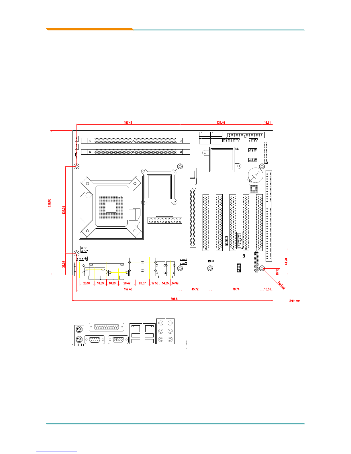
1.10 Board Dimensions
Unit : mm
78.74
45.72
16.51
304.8
157.48
14.9914.3517.5320.5726.4218.0318.0323.37
41.28
33.02 132.08
16.51124.46157.48
10.16
219.96
7-ø4.00
Mouse
Keyboard
USB1
USB2
USB3
USB4
Parallel Port
COM1 Port
VGA
- 8 -
Introduction
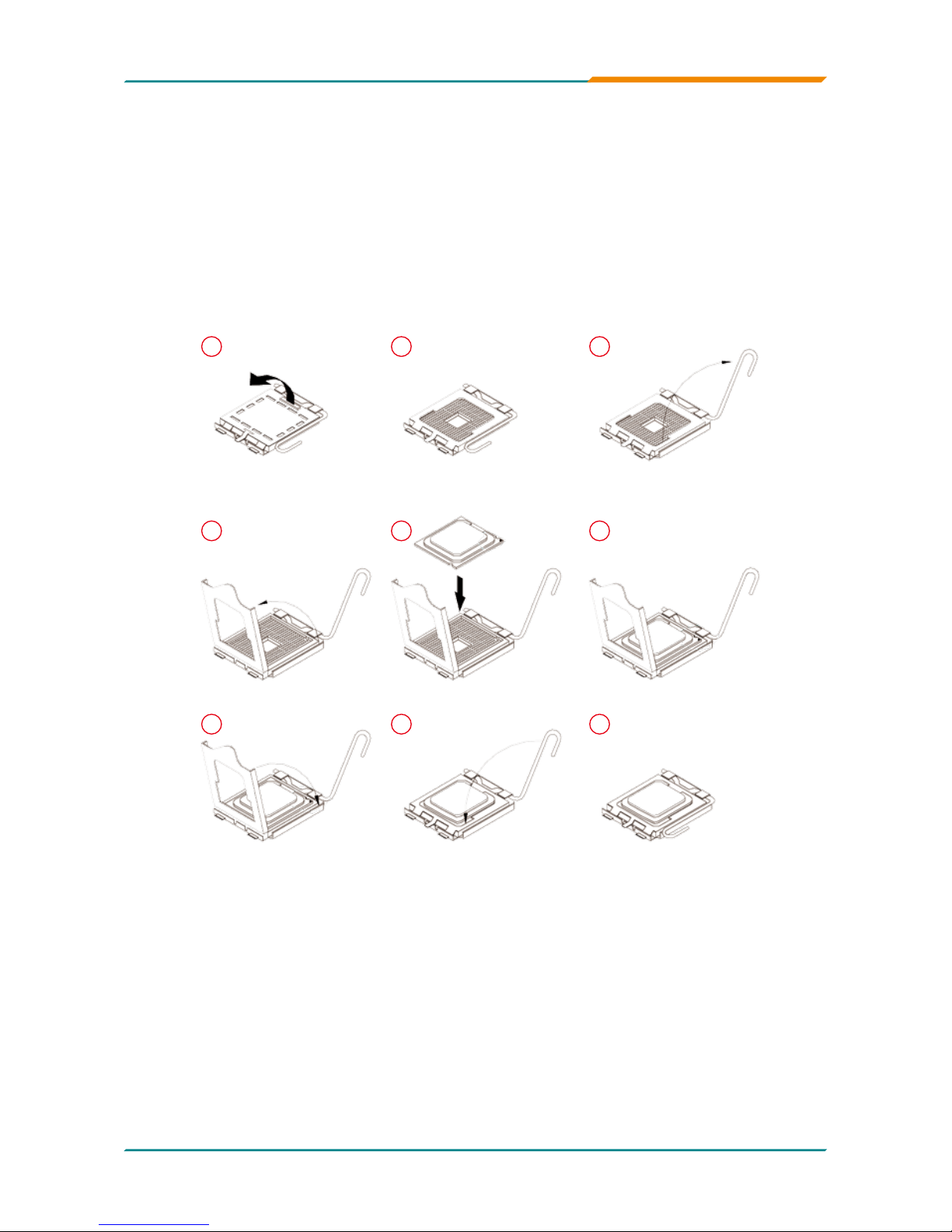
1.11 Installing the CPU
The LGA775 processor socket comes with a lever to secure the
processor. Please refer to the pictures step by step as below.
Please note that the cover of the LGA775 socket must always be installed
during transport to avoid damage to the socket.
Make sure that heat sink of the CPU top surface is in complete contact to
avoid the CPU overheating problem.
If not, it would cause your system or CPU to be hanged, unstable, damaged.
1 2 3
654
7 8 9
- 9 -
Introduction
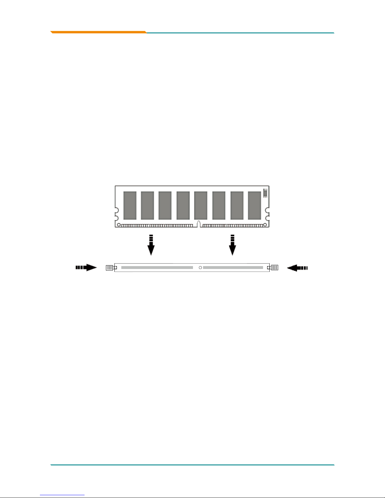
1.12 Installing the Memory
To install the Memory module, locate the Memory DIMM slot on the board
and perform as below:
1. Hold the Memory module so that the key of the Memory module align
with those on the Memory DIMM slot.
2. Gently push the Memory module in an upright position and a right way
until the clips of the DIMM slot close to lock the Memory module in place,
when the Memory module touches the bottom of the DIMM slot.
3. To remove the Memory module, just pressing the clips of DIMM slot with
both hands.
Lock Lock

- 10 -
Introduction
This page is intentionally left blank.

- 11 -
Installation
2Chapter 2
Installation
Chapter 2 - Installation
- 12 -
Installation
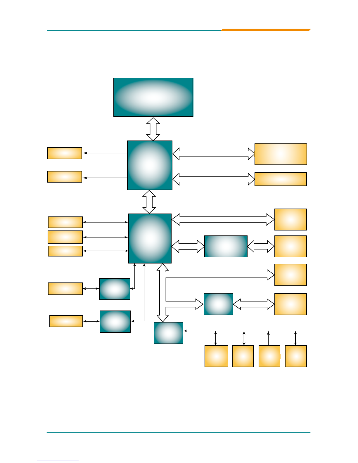
2.1 Block Diagram
Analog
R.G.B.
VGA
LVDS
Intel®
GME965
Intel® Core™2 Duo/
Celeron® M
Processors
FSB
533/800MHz
DMI I/F
USB I/F
Serial ATA I/F
IDE ATA I/F
Intel®
ICH8M
DIO
1 x IDE
10 x USB
3 x SATA
HD Audio
Memory Bus
PCIe Bus
Super IO
COM1
COM2
LPT1
FDD
IrDA
KB
MS
Codec
AC’97
5 x PCI slot
GPIO
SMBus
LVDS
LPC I/F
PCIe LAN
Controller
2 x LAN
RJ-45
1 x slot PCIe*16
1 x Slot PCIe*4
2 x 240pin DDRII
DIMM socket
PCIe x1
PCI Bus
UART
1.2
COM3
COM4
TPM 1.2
- 13 -
Installation
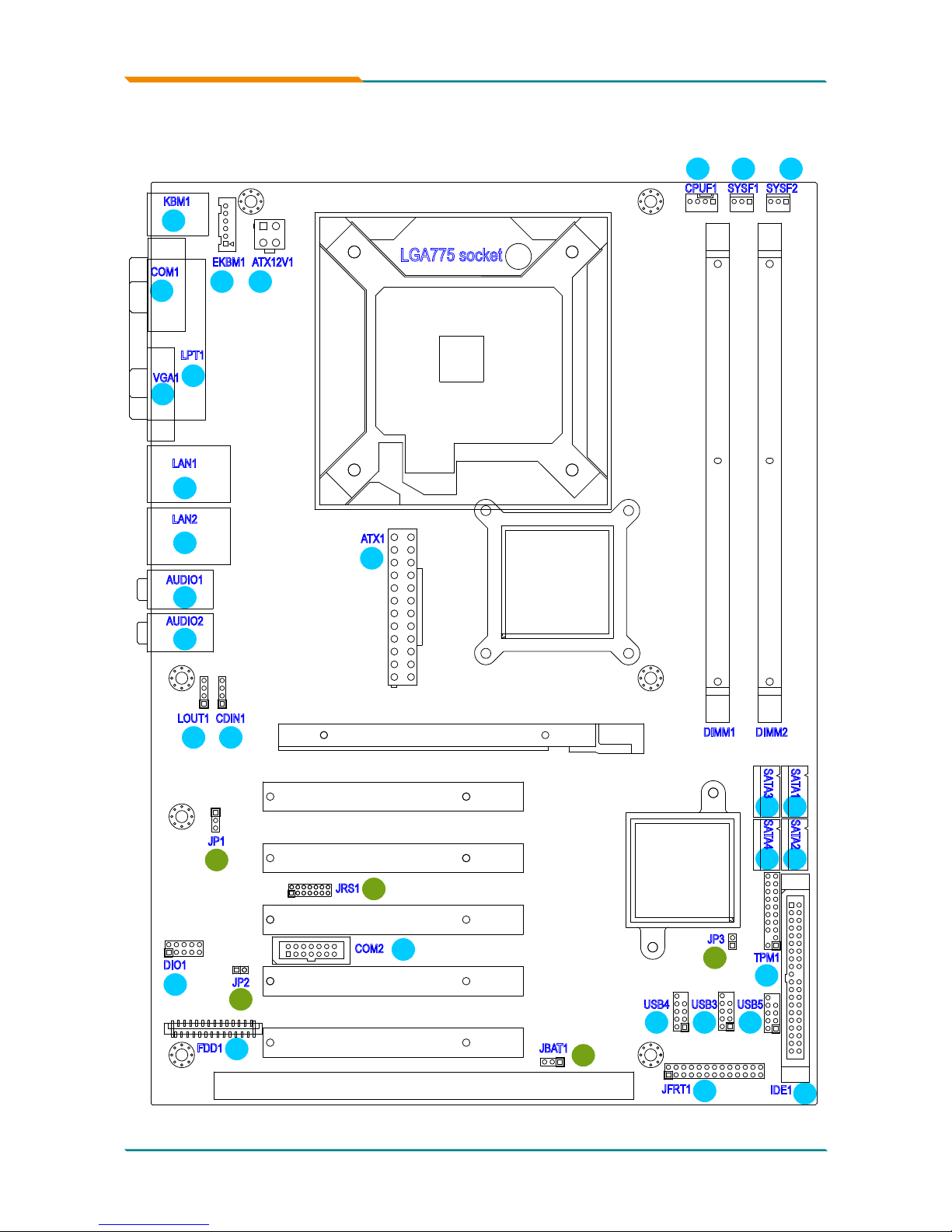
2.2 Jumpers and Connectors
25
24
23
22
16
29
27
28
26
18 17
19
1
2
3
4
7
89
10
5
6
DIMM1
DIMM2
LGA775 socket
SYSF2SYSF1CPUF1
ATX12V1EKBM1
KBM1
SATA3
SATA4
SATA1 SATA2
USB5USB3USB4
TPM1
IDE1
JFRT1
JBAT1
JP3
JP2
FDD1
DIO1
JRS1
JP1
CDIN1
AUDIO1
AUDIO2
LAN1
COM1
LPT1
LAN2
VGA1
LOUT1
COM2
ATX1
15 14
34
13
12
11
2021
33
32
31
30
- 14 -
Installation
Jumpers
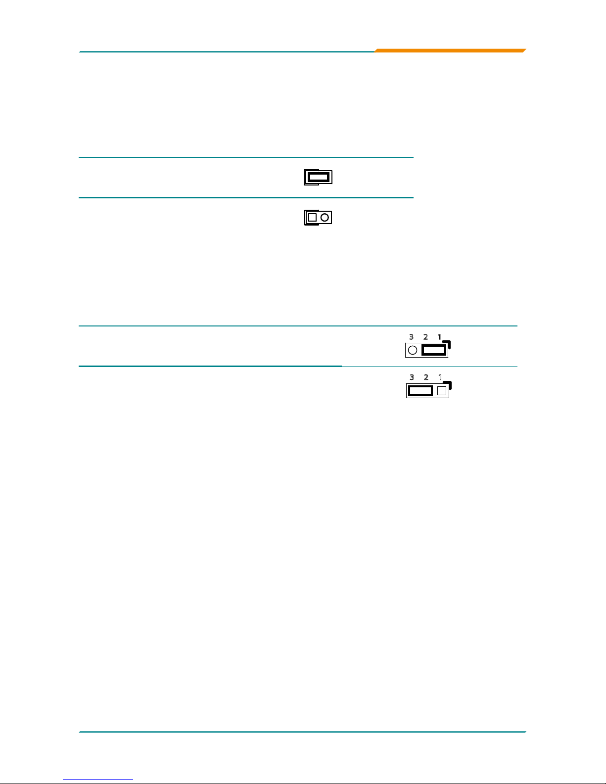
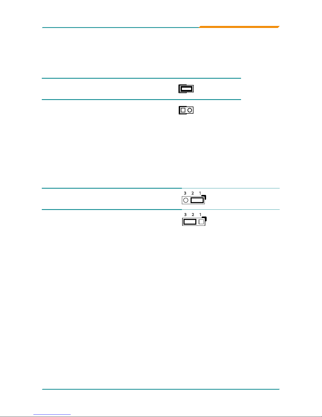
JP3: PATA IDE Select (30)
Connector type: 2.54mm pitch 1x2 pin header.
Pin 1-2 Function Select
Short Disable
1 2
Open Enable (Default)
1 2
JBAT1: CMOS Setup (31)
If the board refuses to boot due to inappropriate CMOS settings here is how
to proceed to clear (reset) the CMOS to its default values.
Connector type: 2.54mm pitch 1x3 pin header
Pin Mode
1-2 Keep CMOS (Default)
23 1
2-3 Clear CMOS
23 1
You may need to clear the CMOS if your system cannot boot up because
you forgot your password, the CPU clock setup is incorrect, or the CMOS
settings need to be reset to default values after the system BIOS has been
updated.
Refer to the following solutions to reset your CMOS setting:
Solution A:
1. Power off the system and disconnect the power cable.
2. Place a shunt to short pin 1 and pin 2 of JBAT1 for ve seconds.
3. Place the shunt back to pin 2 and pin 3 of JBAT1.
4. Power on the system.
Solution B:
If the CPU Clock setup is incorrect, you may not be able to boot up. In this
case, follow these instructions:
1. Turn the system off, then on again. The CPU will automatically boot up
using standard parameters.
2. As the system boots, enter BIOS and set up the CPU clock.
Note:
If you are unable to enter BIOS setup, turn the system on and off a few
times.
- 15 -
Installation
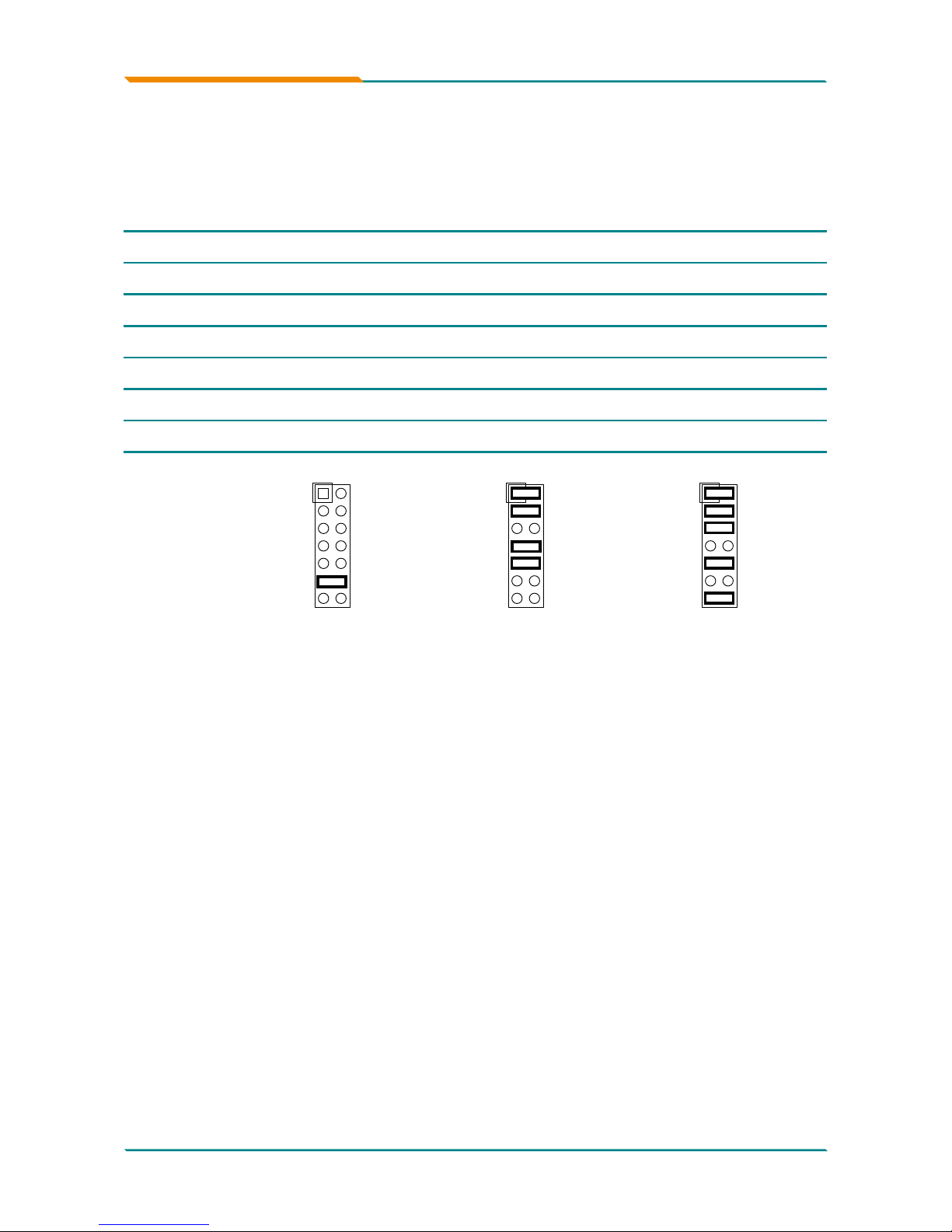
JRS1: COM2 RS-232/RS-422/RS-485 Mode Select (32)
Connector type: 2.00 mm pitch 2x7 pin header
Mode
RS-232
(Default)
RS-422 RS-485
1-2 Off On On
3-4 Off On On
5-6 Off Off On
7-8 Off On Off
9-10 Off On On
11-12 On Off Off
13-14 Off Off On
1 2
13 14
1 2
13 14
1 2
13 14
- 16 -
Installation
JP2: AT/ATX Power Mode Select (33)
The power mode jumper selects the power mode for the system.
Connector type: 2.54mm pitch 1x2 pin header.
Pin 1-2 Mode
Short AT Mode
1 2
Open ATX Mode (Default)
1 2
JP1: BIOS Write protect (34)
Connector type: 2.54mm pitch 1x3 pin header.
Pin Mode
1-2 Write protect (default)
23 1
2-3 Write Enable
23 1
- 17 -
Installation
Connectors
SATA1~4: Serial ATA Connectors (1), (2), (3), (4)
There are on board supports four SATA II connectors, second generation
SATA drives transfer data at speeds as high as 300MB/s, twice the transfer
speed of rst generation SATA drives. The SATA drives can be congured in
a RAID 0, RAID 1 or RAID 10 conguration.
Pin Description
1 GND
2 TX+
3 TX-
4 GND
5 RX-
6 RX+
7 GND
- 18 -
Installation
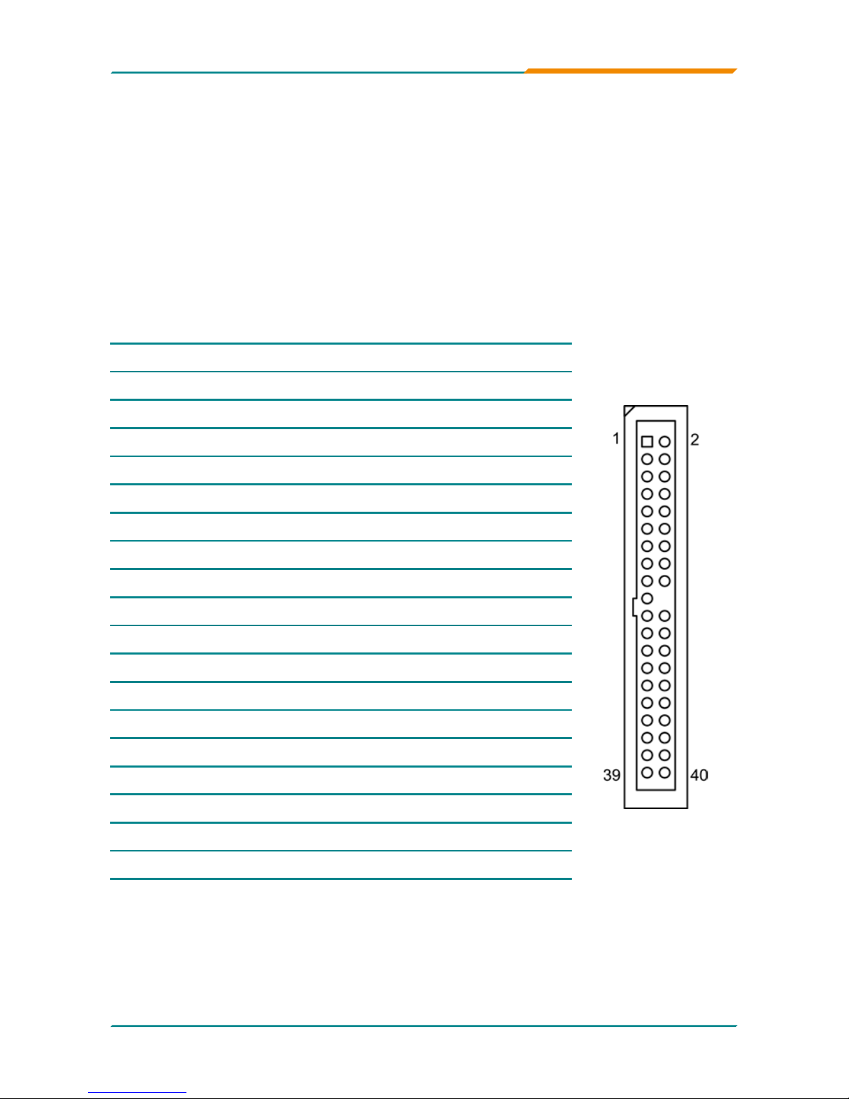
IDE1: Primary IDE Connector (5)
An IDE drive ribbon cable has two connectors to support two IDE devices. If
a ribbon cable connects to two IDE drives at the same time, one of them has
to be congured as Master and the other has to be congured as Slave by
setting the drive select jumpers on the drive.
Consult the documentation that came with your IDE drive for details on
jumper locations and settings. You must orient the cable connector so that
the pin 1 (color) edge of the cable corresponds to pin 1 of the IDE connector.
Connector type: 2.54mm pitch 2x20 box header
Pin Description Pin Description
1 IDE RESET 2 GND
3 DATA7 4 DATA8
5 DATA6 6 DATA9
7 DATA5 8 DATA10
9 DATA4 10 DATA11
11 DATA3 12 DATA12
13 DATA2 14 DATA13
15 DATA1 16 DATA14
17 DATA0 18 DATA15
19 GND 20 N/C (Key)
21 REQ 22 GND
23 IO WRITE 24 GND
25 IO READ 26 GND
27 IO READY 28 IDESEL
29 DACK 30 GND
31 IRQ14 32 N/C
33 ADDR1 34 ATA66 DETECT
35 ADDR0 36 ADDR2
37 CS0# 38 CS1# (HDSELET1)
39 IDEACTP 40 GND
- 19 -
Installation
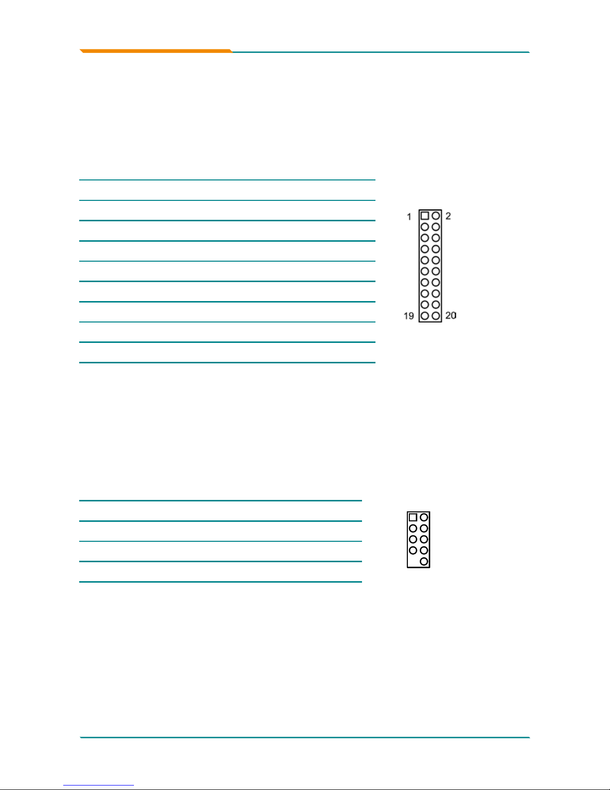
TPM1: Trusted Platform Module Connector (6)
The TPM connector on the EmCORE-i35Q is interfaced to the Intel ICH9
south bridge through the LPC bus. The ICH9 supports TPM version 1.2
devices for enhanced security.
Connector type: 2.54mm pitch 2x10 pin header
Pin Description Pin Description
1 CLK 2 GND
3 LFRAME 4 N/C
5 LRESET 6 N/C
7 LAD3 8 LAD2
9 +3.3V 10 LAD1
11 LAD0 12 GND
13 N/C 14 N/C
15 +3.3V_SB 16 SERIRQ
17 GND 18 CLKRUN
19 PD 20 N/C
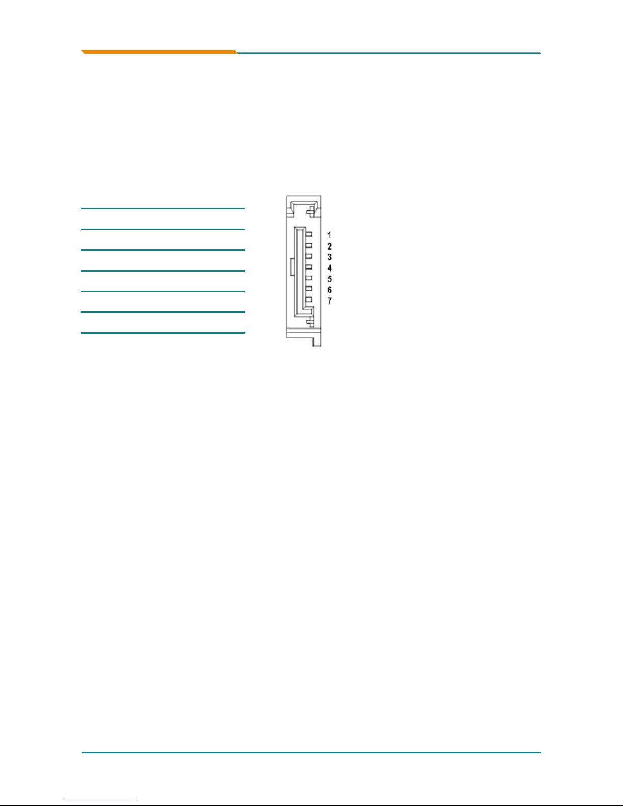
USB1/ USB2/ USB3: USB Connectors (7), (8), (9)
On board supports three headers USB1, USB2, and USB3 that can connect
up to six high-speed (Data transfers at 480MB/s), full-speed (Data transfers
at 12MB/s) or low-speed (Data transfers at 1.5MB/s) USB devices.
Connector type: 2.54mm 2x5 pin header
Pin Description Pin Description
1
2
10
9
1 +5V 2 +5V
3 USBD- 4 USBD-
5 USBD+ 6 USBD+
7 GND 8 GND
9 N/C (Key) 10 N/C
- 20 -
Installation
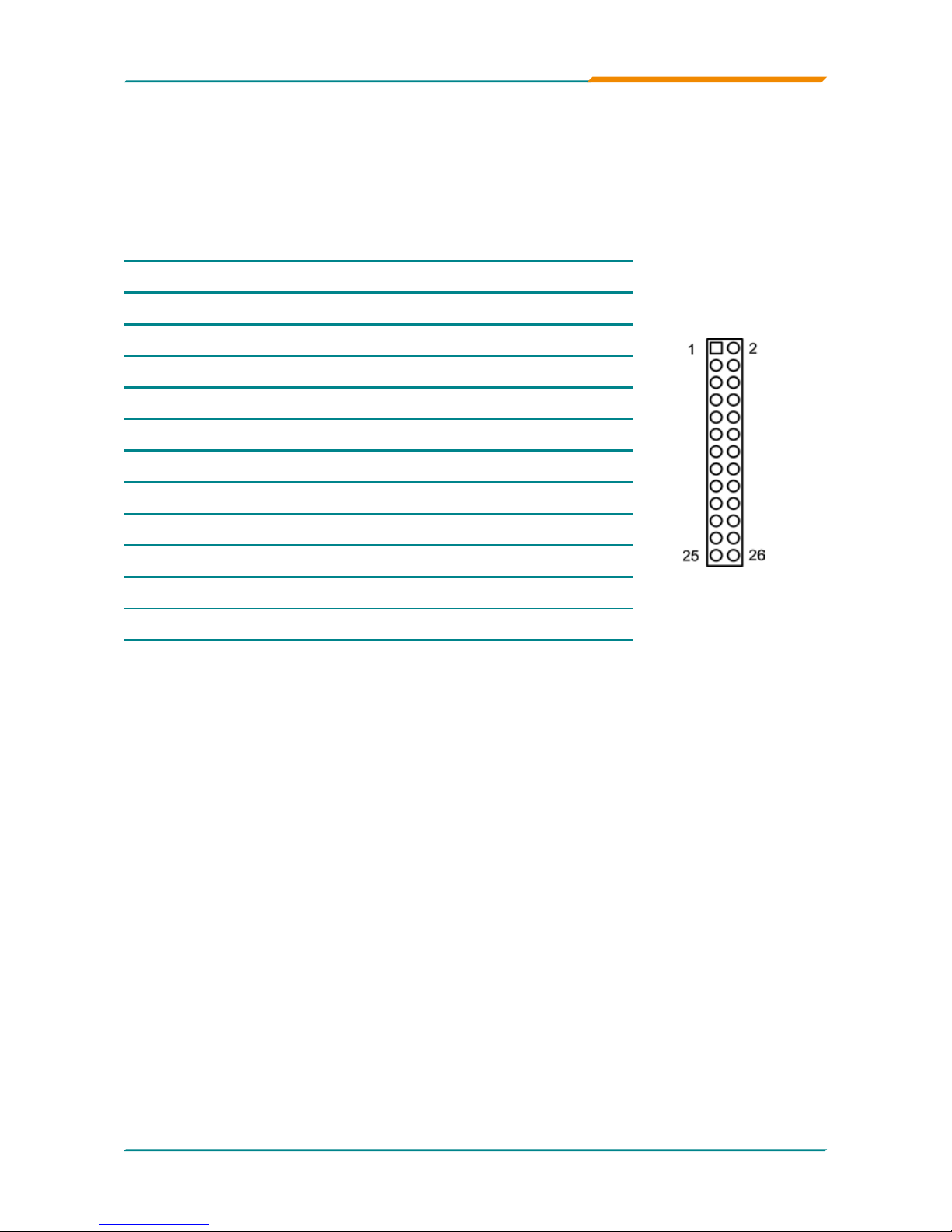
JFRT1: Switches and Indicators (10)
It provides connectors for system indicators that provides light indication
of the computer activities and switches to change the computer status.
Connector type: 2.54mm pitch 2x13 pin header
Pin Description Pin Description
1 +5V 2 RESET+
3 N/C 4 RESET-
5 IRRX 6 N/C
7 GND 8 SPKR
9 IRTX 10 BUZZ
11 N/C 12 GND
13 HDD_LED+ 14 +5V
15 HDD_LED- 16 N/C
17 TB_LED+ 18 POWER_LED+
19 TB_LED- 20 N/C
21 N/C 22 POWER_LED-
23 PWRBTN+ 24 KBLOCK
25 PWRBTN- 26 GND
IrDA: Infrared connector, pin 1, 3, 5, 7, 9
HLED: HDD LED Connector, pin 13-15.
This 2-pin connector connects to the case-mounted HDD LED to indicate hard
disk activity.
RES: Reset Button, pin 2-4.
This 2-pin connector connects to the case-mounted reset switch and is used to
reboot the system.
TB_LED: pin 17-19
PWRBTN: ATX soft power switch, pin 23-25.
This 2-pin connector connects to the case-mounted Power button.
PLED: Power LED Connector, pin 18, 20, 22.
This 3-pin connector connects to the case-mounted power LED. Power LED can
be indicated when the CPU card is on or off. And keyboard lock can be used to
disable the keyboard function so the PC will not respond by any input.
SPK: External Speaker, pin 8, 10, 12, 14.
This 4-pin connector connects to the case-mounted speaker.
KBLOCK: Keyboard Lock, pin 24-26.
 Loading...