

ATX Maxnet II QMP200 Installation & Operation Manual

QMP200 Return RF/IF Amplier
Installation & Operation Manual
CCAP
Com
™
pliant
1.2 GHz

Although every effort has been taken to ensure the accuracy of this document it may be necessary, without notice, to make amendments or correct omissions.
Specications subject to change without notice.
MAXNET® II is a registered trademark of ATX in the United States and/or other countries. Products or features contained herein may be covered by one or more U.S. or foreign
patents. Other non-ATX product and company names in this manual are the property of their respective companies.

TABLE OF CONTENTS
Page
1. PRODUCT DESCRIPTION ........................................................................................................................ 1-1
1.1. Functional Diagram ........................................................................................................................... 1-2
1.2. Technical Specications .................................................................................................................... 1-2
2. INSTALLATION .........................................................................................................................................2-1
2.1. Product Inspection ............................................................................................................................. 2-1
2.2. Module Installation into the Active MAXNET® II Chassis .................................................................. 2-1
2.3. RF Connections ................................................................................................................................. 2-1
2.4. Amplier Set-Up ................................................................................................................................ 2-2
3. STATUS MONITORING .............................................................................................................................3-1
3.1. Chassis Interface Options ................................................................................................................. 3-1
3.2. SCTE HMS MIB Software Denition of Module................................................................................. 3-1
3.3. Web Interface .................................................................................................................................... 3-1
3.4. Updating Active Chassis Firmware .................................................................................................... 3-2
3.5. Factory Reset .................................................................................................................................... 3-2
4. STATUS MONITORING FEATURES ......................................................................................................... 4-1
4.1. SNMP Parameters .............................................................................................................................4-1
4.2. SNMP MIBs Required ....................................................................................................................... 4-2
5. MAINTENANCE & TROUBLESHOOTING ................................................................................................ 5-1
5.1. Maintenance ...................................................................................................................................... 5-1
5.2. Troubleshooting ................................................................................................................................. 5-1
6. SERVICE & SUPPORT ..............................................................................................................................6-1
6.1. Contact ATX Networks ....................................................................................................................... 6-1
6.2. Warranty Information ......................................................................................................................... 6-1
6.3. Safety ................................................................................................................................................ 6-1
MAXNET® II – QMP200 Return RF/IF Amplier Manual – Installation & Operation Manual i

Index of Figures and Tables
Figures
#1 Return RF/IF Amplier Functional Diagram .................................................1-2
#2 Front & Rear Panel Pictures ........................................................................2-1
#3 Front Panel Plug-ins ....................................................................................2-2
Tables
#1 Ordering Information ....................................................................................1-1
#2 Technical Specications ..............................................................................1-2
#3 LED Status Indications ................................................................................2-2
#4 Plug-in PAD Specications ..........................................................................2-3
#5 Plug-in 1 GHz EQ Specications .................................................................2-3
#6 Plug-in 1.218 GHz EQ Specications ..........................................................2-3
#7 Plug-in PAD/EQ Ordering Information .........................................................2-3
#8 Common Module SNMP Parameters ..........................................................4-1
#9 QMP200 SNMP Parameters ........................................................................4-1
#10 General SCTE HMS MIBs Required ...........................................................4-2
#11 QMP200 SCTE HMS MIBs Required ..........................................................4-2
ii MAXNET® II – QMP200 Return RF/IF Amplier Manual – Installation & Operation Manual

CHAPTER 1: PRODUCT DESCRIPTION
Part Number Description
PRODUCT DESCRIPTION
1. Product Description
The QMP200 MAXNET II modules are Return RF/IF Ampliers, which offer two gain versions (20 dB and 28 dB) that are
determined at the time of ordering. The QMP200 amplier is a single stage amplier as shown in the functional diagram. The
QMP200 ampliers are dual-width, taking up two slots in the Active MAXNET II Chassis and they are powered through a
hot-swapping backplane in the Active MAXNET II Chassis. An appropriate MAXNET II Power Supply in the Active MAXNET II
Chassis powers these modules. The QMP200 modules feature the standard MAXNET II functionality including high-density
packaging through the use of MCX coaxial cable connectors in conjunction with Mini RG-59 Type coaxial cable. Also featured
are: front access alarm LED indicator, -20 dB test points and the capability of module status monitoring through SNMP based
Managers. The MAXNET II SNMP interface is HMS compliant.
Please refer to the web page for up-to-date specications – www.atxnetworks.com
QMP200-28L 200 MHz, 28 dB Gain Single Stage, MCX Connectors
QMP200-20L 200 MHz, 20 dB Gain Single Stage, MCX Connectors
QMP200-28LF 200 MHz, 28 dB Gain Single Stage, F Connectors
QMP200-20LF 200 MHz, 20 dB Gain Single Stage, F Connectors
Table #1: Ordering Information
MAXNET® II – QMP200 Return RF/IF Amplier Manual – Installation & Operation Manual 1-1
CHAPTER 1: PRODUCT DESCRIPTION
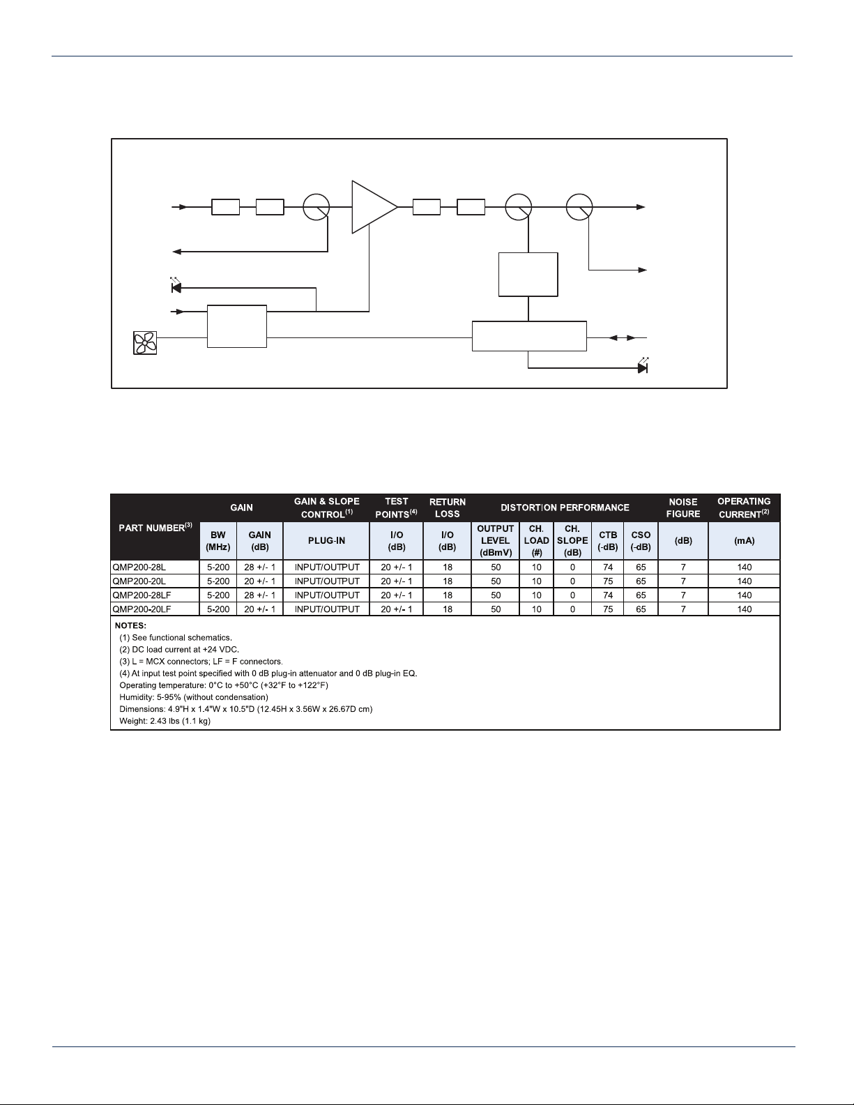
1.1. Functional Diagram
Return RF/IF Amplifier
RF INPUT
-20 dB INPUT
TEST POINT
PWR
+24 VDC
FAN
ACTIVE FUSE,
POWER &
FAN CTRL
Figure #1: Return RF/IF Amplier Functional Diagram
1.2. Technical Specications
PAD EQPAD EQ
RF
DETECTOR
MONITOR & CONTROL
RF OUTPUT
-20 dB OUTPUT
TEST POINT
CHASSIS
COMM.
ALARM
Table #2: Technical Specications
1-2 MAXNET® II – QMP200 Return RF/IF Amplier Manual – Installation & Operation Manual
 Loading...