

ATX Maxnet II Platinum Installation & Operation Manual
CCAP
Com
pliant
MPAC/MPDC Modular Power Supply
Installation & Operation Manual
™
1.2 GHz

Although every effort has been taken to ensure the accuracy of this document it may be necessary, without notice, to make amendments or correct omissions.
Specications subject to change without notice.
MAXNET® II is a registered trademark of ATX in the United States and/or other countries. Products or features contained herein may be covered by one or more U.S. or foreign
patents. Other non-ATX product and company names in this manual are the property of their respective companies..

TABLE OF CONTENTS
Page
1. PRODUCT DESCRIPTION ........................................................................................................................ 1-1
1.1. Functional Diagrams.......................................................................................................................... 1-2
1.2. Technical Specications .................................................................................................................... 1-3
2. INSTALLATION .........................................................................................................................................2-1
2.1 Product Inspection ............................................................................................................................. 2-1
2.2. Module Installation Into the Active MAXNET® II Chassis .................................................................. 2-1
2.3. DC Redundant Powering of Active MAXNET® II Chassis ................................................................. 2-2
2.4. Remote Powering of Additional Active MAXNET® II Chassis’ ........................................................... 2-2
2.5. Module Power Requirements ............................................................................................................ 2-3
2.6 LED Indicators ................................................................................................................................... 2-3
3. STATUS MONITORING ............................................................................................................................. 3-1
3.1. Chassis Interface Options ................................................................................................................. 3-1
3.2. SCTE HMS MIB Software Denition of Module................................................................................. 3-1
3.3. Web Interface .................................................................................................................................... 3-1
3.4. Updating Active Chassis Firmware .................................................................................................... 3-2
3.5. Factory Reset .................................................................................................................................... 3-2
4. STATUS MONITORING FEATURES ......................................................................................................... 4-1
4.1. SNMP Parameters .............................................................................................................................4-1
4.2. SNMP MIBs Required for MPAC & MPDC ........................................................................................ 4-2
5. MAINTENANCE & TROUBLESHOOTING ................................................................................................ 5-1
5.1. Maintenance ...................................................................................................................................... 5-1
5.2. Troubleshooting ................................................................................................................................. 5-1
6. SERVICE & SUPPORT ..............................................................................................................................6-1
6.1. Contact ATX Networks .......................................................................................................................6-1
6.2. Warranty Information ......................................................................................................................... 6-1
6.3. Safety ................................................................................................................................................ 6-1
MAXNET® II – MPAC/MPDC Modular Power Supply – Installation & Operation Manual i

Index of Figures and Tables
Figures
#1 MPAC Power Supply Functional Diagram ................................................... 1-2
#2 MPDC Power Supply Functional Diagram ...................................................1-2
#3 Front & Rear Panel Pictures ........................................................................2-2
#4 Remote Powering ........................................................................................2-2
#5 Redundant Powering ...................................................................................2-2
Tables
#1 Ordering Information ....................................................................................1-1
#2 Technical Specications ..............................................................................1-3
#3 Rear Terminal Block Assignments ...............................................................2-1
#4 LED Status Indications ................................................................................2-3
#5 Common Module SNMP Parameters ..........................................................4-1
#6 MPAC & MPDC SNMP Parameters ............................................................. 4-1
#7 SCTE HMS MIBs Required .........................................................................4-2
ii MAXNET® II – MPAC/MPDC Modular Power Supply – Installation & Operation Manual

CHAPTER 1: PRODUCT DESCRIPTION
Part Number Description
MPAC-110 110 VAC to 24 VDC 250W Power Supply
MPAC-220 220 VAC to 24 VDC 250W Power Supply
PRODUCT DESCRIPTION
1. Product Description
The MPAC and MPDC are modular power supplies that supply the required +24 VDC to the MAXNET II Active Chassis
back plane. This allows any MAXNET II active module (RPR’s, FPT’s, AMP’s, RF switcher) to be installed in any remaining
active chassis slot to receive power. Both MPAC and MPDC have 24 VDC redundant powering capabilities, although
only the MPDC offers true load sharing logic. Installing two power supply modules into a chassis will thus ensure power
to the backplane if one of them fails. Both the MPAC and MPDC include a 24 VDC rear terminal block connection for
remote powering options. The MPAC and MPDC power supply modules are dual-width, taking up two slots in the Active
MAXNET II Chassis. They are connected to the Active MAXNET II Chassis through a hot-swapping backplane. The MPAC
and MPDC modules feature the standard MAXNET II functionality including front panel power and alarm LED indicators as
well as the capability of module status monitoring through SNMP based Managers. The MAXNET II SNMP interface is HMS
compliant.
Please refer to the web page for up-to-date specications – www.atxnetworks.com
MPDC -48 VDC to 24 VDC 250W Power Supply
Table #1: Ordering Information
MAXNET® II – MPAC/MPDC Modular Power Supply – Installation & Operation Manual 1-1
CHAPTER 1: PRODUCT DESCRIPTION
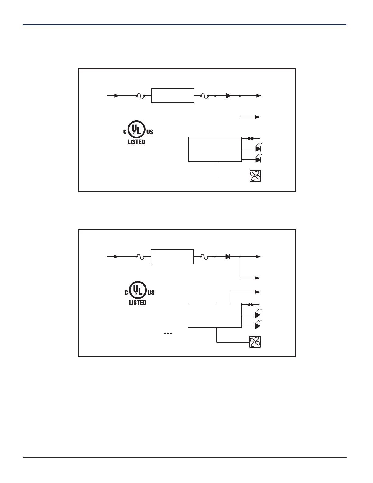
1.1. Functional Diagrams
AC Power Supply
110 or
220 VAC
IN
INPUT VOLTAGE: 110 or 220 VOLTS AC
CURRENT: 4.0A/2.2A (110 or 220 VAC)
FUSE
6.3A
(3.15A for 220V)
250V
ACCESSORY
I.T.E. POWER SUPPLY
E226099
5UA5
FREQ: 50/60 HZ
POWER SUPPLY
MODULE
FUSE
15A
250V
MONITOR AND CONTROL
Figure #1: MPAC Power Supply Functional Diagram
ATTENTION: NOT A UNIVERSAL
VOLTAGE INPUT !
REFER TO ORDERING
INFORMATION FOR DETAILS
+24V
BUS
+24V
OUT
(REAR)
CHASSIS
COMM.
PWR
ALM
FAN
DC Power Supply
-48 VDC
IN
I.T.E. POWER SUPPLY
INPUT VOLTAGE: -48 VOLTS DC
INPUT CURRENT: 5.0A
Figure #2: MPDC Power Supply Functional Diagram
FUSE
10A
250V
ACCESSORY
E226099
5UA5
POWER SUPPLY
MODULE
FUSE
15A
250V
MONITOR AND CONTROL
+24 V
BUS
+24V
OUT
(REAR)
I SHARE
CHASSIS
COMM.
PWR
ALM
FAN
1-2 MAXNET® II – MPAC/MPDC Modular Power Supply – Installation & Operation Manual
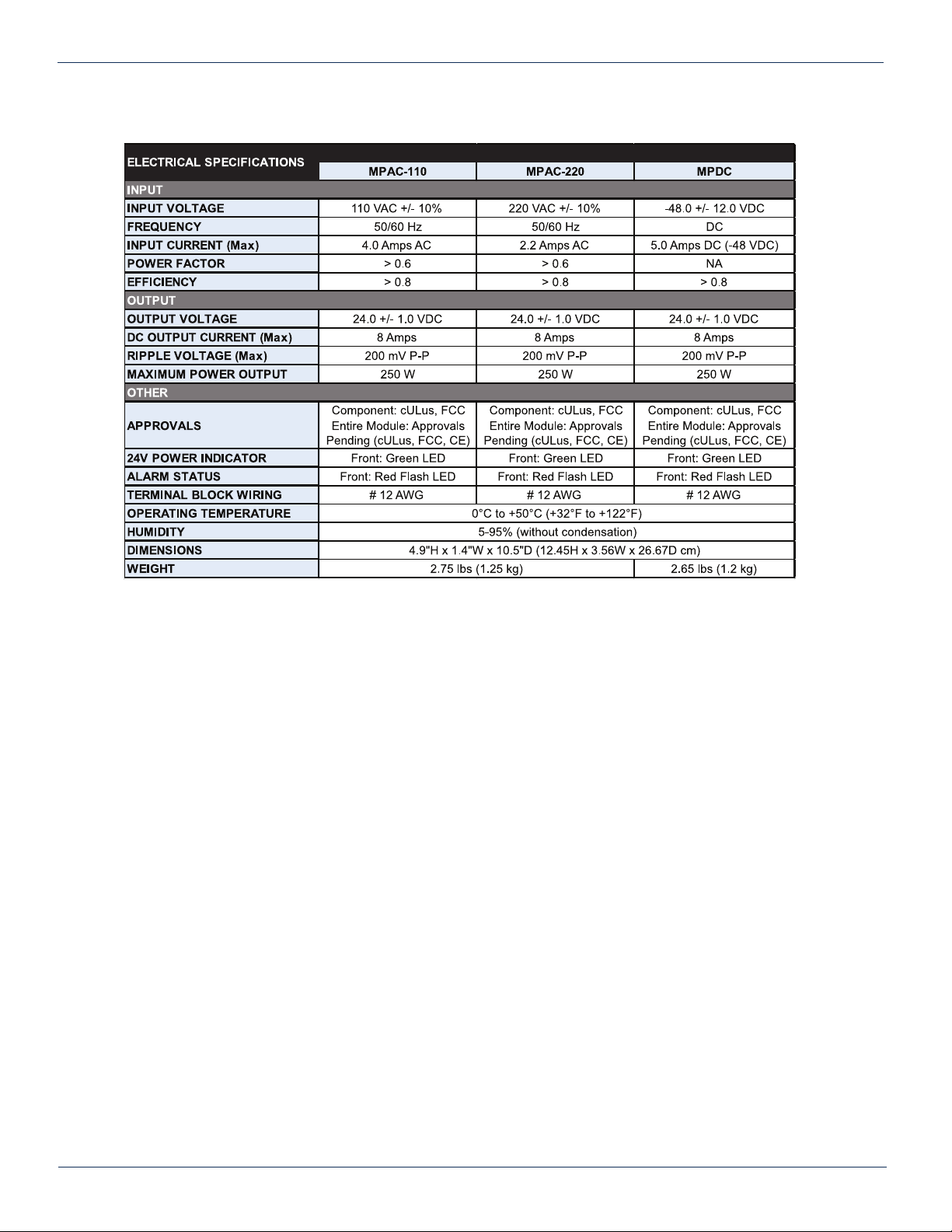
1.2. TechnicalSpecications
Table#2:TechnicalSpecications
MAXNET® II – MPAC/MPDC Modular Power Supply – Installation & Operation Manual 1-3

CHAPTER 1: PRODUCT DESCRIPTION
This page left intentionally blank.
1-4 MAXNET® II – MPAC/MPDC Modular Power Supply – Installation & Operation Manual
 Loading...