

ATX MAXNET II MPRFA, MAXNET II MPRFB Installation & Operation Manual

MPRFA/B RF Detector A/B Switch
Installation & Operation Manual
CCAP
Com
™
pliant
1.2 GHz

Although every effort has been taken to ensure the accuracy of this document it may be necessary, without notice, to make amendments or correct omissions.
Specications subject to change without notice.
MAXNET® II is a registered trademark of ATX in the United States and/or other countries. Products or features contained herein may be covered by one or more U.S. or foreign
patents. Other non-ATX product and company names in this manual are the property of their respective companies.

TABLE OF CONTENTS
Page
1. PRODUCT DESCRIPTION ........................................................................................................................ 1-1
1.1. Functional Diagrams.......................................................................................................................... 1-2
1.2. Technical Specications .................................................................................................................... 1-2
2. INSTALLATION .........................................................................................................................................2-1
2.1. Product Inspection ............................................................................................................................. 2-1
2.2. Module Installation into the Active MAXNET® II Chassis .................................................................. 2-1
2.3. RF Connections ................................................................................................................................. 2-1
2.4 RF Detector Switch Set-up ................................................................................................................ 2-2
2.5. Application Examples ........................................................................................................................ 2-3
3. STATUS MONITORING .............................................................................................................................3-1
3.1. Chassis Interface Options ................................................................................................................. 3-1
3.2. SCTE HMS MIB Software Denition of Module................................................................................. 3-1
3.3. Web Interface .................................................................................................................................... 3-1
3.4. Updating Active Chassis Firmware .................................................................................................... 3-2
3.5. Factory Reset .................................................................................................................................... 3-2
4. STATUS MONITORING FEATURES ......................................................................................................... 4-1
4.1. SNMP Parameters .............................................................................................................................4-1
4.2. SNMP MIBs Required ....................................................................................................................... 4-3
5. MAINTENANCE & TROUBLESHOOTING ................................................................................................ 5-1
5.1. Maintenance ...................................................................................................................................... 5-1
5.2. Troubleshooting ................................................................................................................................. 5-1
6. SERVICE & SUPPORT ..............................................................................................................................6-1
6.1. Contact ATX Networks ....................................................................................................................... 6-1
6.2. Warranty Information ......................................................................................................................... 6-1
6.3. Safety ................................................................................................................................................ 6-1
MAXNET® II – MPRFA/B RF Detector A/B Switch Manual – Installation & Operation Manual i

Index of Figures and Tables
Figures
#1 RF Detector A/B Switch Functional Diagram ...............................................1-2
#2 Front & Rear Panel Pictures ........................................................................ 2-1
#3 Front Panel Pushbutton ............................................................................... 2-2
#4 Redundant Amplier Application ..................................................................2-3
#5 Redundant Source Application ....................................................................2-3
Tables
#1 Ordering Information .................................................................................... 1-1
#2 Technical Specications ..............................................................................1-2
#3 LED Status Indications ................................................................................2-2
#4 Common Module SNMP Parameters ..........................................................4-1
#5 RF Switch SNMP Parameters .....................................................................4-2
#6 General SCTE HMS MIBs Required ...........................................................4-3
#7 MPRFA/B SCTE HMS MIB’s Required ........................................................4-3
ii MAXNET® II – MPRFA/B RF Detector A/B Switch Manual – Installation & Operation Manual
CHAPTER 1: PRODUCT DESCRIPTION
Part Numbe r Description
PRODUCT DESCRIPTION
1. Product Description
The MPRFA/B MAXNET II module is an RF Detector A/B Switch, which provides redundancy for use of multiple RF Ampliers
or RF Sources. It has an integrated 2-way splitter for easy realisation of redundancy scenarios (see Application Examples –
3.5.). The integrated splitter allows for maximized rack space saving and comfortable cable/signal management.
The MPRFA/B RF Detector switch module is dual-width, taking up two slots in the Active MAXNET II Chassis and it is
powered through a hot-swapping backplane in the Active MAXNET II Chassis. An appropriate MAXNET II Power
Supply in the Active MAXNET II Chassis powers these modules. The MPRFA/B module features the standard
MAXNET II functionality including high-density packaging through the use of MCX coaxial cable connectors in conjunction
with Mini RG-59 Type coaxial cable. Also featured are: front access alarm/status LED indicators, a -20 dB test point
and the capability of module status monitoring through SNMP based Managers. The MAXNET II SNMP interface is
HMS compliant.
Please refer to the web page for up-to-date specications – www.atxnetworks.com
MPRFA/B 1002 MHz, RF Detector / Switch, MCX Connectors
MPRFA/BH 1218 MHz, RF Detector / Switch, MCX Connectors
MPRFA/BF 1002 MHz, RF Detector / Switch, F Connectors
MPRFA/BFH 1218 MHz, RF Detector / Switch, F Connectors
Table #1: Ordering Information
MAXNET® II – MPRFA/B RF Detector A/B Switch Manual – Installation & Operation Manual 1-1

CHAPTER 1: PRODUCT DESCRIPTION
1.1. Functional Diagrams
RF Detector & A/B Switch with 2-Way Splitter
+24 VDC
CHASSIS
COMM.
A IN
B IN
P1
P2
COMMON
ACTIVE FUSE
& POWER
CTRL
MONITOR & CONTROL
RF
DETECTOR
RF
DETECTOR
INTEGRATED SPLITTER/ COMBINER
CTRL
MPRFA/B
Figure #1: RF Detector A/B Switch Functional Diagram
PWR
A
B
CHANGE
DEFAULT
-20dB
OUTPUT
TEST
POINT
RF
OUTPUT
1.2. TechnicalSpecications
Table#2:TechnicalSpecications
1-2 MAXNET® II – MPRFA/B RF Detector A/B Switch Manual – Installation & Operation Manual
INSTALLATION
2. Installation
2.1. Product Inspection
Carefully unpack the switch module from the shipping box. If the box or switch module is damaged, please notify the freight
company to make a damage claim. If you suspect that there is a problem with the switch module that may affect it’s safe
operation, do not install such a suspect Switch into the Active MAXNET II Chassis.
2.2. Module Installation into the Active MAXNET® II Chassis
Slide the dual-width MPRFA/B switch module into an open slot in the Active MAXNET II Chassis, one that spans two singlewidth module locations beginning with an odd number (indicated by a white marker on the chassis), until the module drops
into its lock position. The module must be inserted into an odd number slot in order for the switch module to properly
mate to the active chassis back plane. If the module is installed properly, the switch will make contact with the 24 VDC
power bus in the chassis and if there is a MAXNET II Power Supply Module installed in the chassis, and it is plugged into
the respective power source, the module’s PWR (Power) LED indicator will light green. To remove a switch module from the
chassis, gently lift the front handle and pull back on the module until it is clear of the chassis guide slot.
Initially, when inserted in the Active MAXNET II chassis, the switch will start alarming (the front panel A LED indicator will start
ashing red), as there are no RF input signals. The switch will stop alarming (the front panel A LED indicator will stop ashing
red) once RF signals are applied to both A IN and B IN rear panel RF jacks.
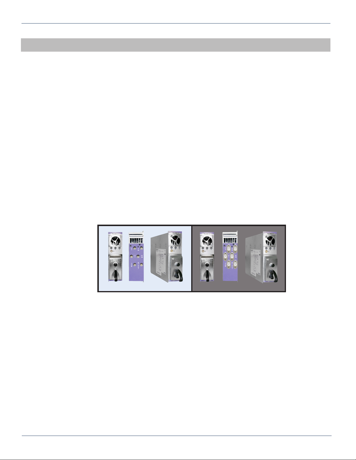
MPRFA/B
Figure #2: Front & Rear Panel Pictures
Shown with MCX (left) and F (right) rear panel connectors
MPRFA/BF
2.3. RF Connections
The RF jacks on the MPRFA/B RF Detector A/B switch’ front/rear panel are MCX [female]. As an option, the RF jacks on
the rear panel can be F type [female]. There will be six RF connectors at the rear plus one front panel -20 dB test point per
MPRFA/B switch. The front panel test point is –20 dB relative to the RF output. The three connectors on the right side of the
rear panel are the A/B switch connectors (starting from top: A IN, B IN, RF OUT) and the three connectors on the left side of
the rear panel are connectors for the integrated 2-way splitter (starting from top: P2, P1, COM).
MAXNET® II – MPRFA/B RF Detector A/B Switch Manual – Installation & Operation Manual 2-1
 Loading...