

ATX ivis Installation And Operation Manual

IVIS - Indoor Video
IVIS
Installation & Operation Manual
Insertion System

Although every effort has been taken to ensure the accuracy of this document it may be necessary, without notice, to make amendments or correct omissions.
Specications subject to change without notice.
MDU Solutions®, UCrypt®, DigiVu® and VersAtive®Pro are registered trademarks of ATX in the United States and/or other countries. Products or features contained herein may be covered by one or
more U.S. or foreign patents. Adobe® Flash® Wikipedia®, and other non-ATX product and company names mentioned in this document are the property of their respective companies.

TABLE OF CONTENTS
Page
1. INTRODUCTION ........................................................................................................................................ 1-1
2. INSTALLATION .........................................................................................................................................2-1
3. AGILE MODULATOR OPERATION .......................................................................................................... 3-1
3.1. Agile Modulator Front Panel Controls................................................................................................ 3-1
4. RF LEVEL ADJUSTMENT ......................................................................................................................... 4-1
5. SERVICE & SUPPORT ..............................................................................................................................5-1
5.1. Contact ATX Networks ....................................................................................................................... 5-1
5.2. Warranty Information ......................................................................................................................... 5-1
5.3. Safety ................................................................................................................................................ 5-1
i MDU Solutions® – IVIS Indoor Video Insertion System - Instalation & Operation Manual i

Index of Figures
Figures
#1 IVIS Unit.......................................................................................................1-1
#2 Agile Modulator ............................................................................................3-1
#3 Functional Schematic ..................................................................................4-1
ii MDU Solutions® – IVIS Indoor Video Insertion System - Instalation & Operation Manual
CHAPTER 1: INTRODUCTION
INTRODUCTION
1. Introduction
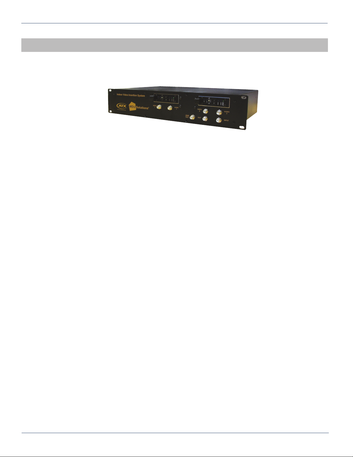
Figure #1: IVIS Unit
This document outlines the set-up and operation of the ATX Indoor Video/Audio Inserter System – IVIS.
The IVIS device takes ATX’s Channel Deletion Filters and integrates them with an agile or xed Video/Audio Modulator
packaged into an indoor housing. The IVIS device is mainly powered for powering the internal integrated Modulators.
The IVIS device allows the operator to delete one or two RF channels from the Cable TV spectrum and reinsert new
programming in Analog modulation format on those deleted channel locations. The new channels can be any Video/Audio
source such as a closed circuit Video Camera or a specialty service that has been demodulated to baseband Audio and
Video using a Set-Top-Box / Converter / Decoder. The latter example allows the operator to move specialty services from
higher tiers to the basic service.
The IVIS system can be ordered with xed or agile modulators. If xed modulators are ordered then their desired output
channel in the Cable TV spectrum has to be specied at time of order. For both modulator types (xed and agile) it has to be
specied at time of order whether the Cable TV channels are Standard, HRC, or IRC.
The RF channel deletion lter frequencies must be specied at time of order always for both modulator types as the lter is
not agile.
If an agile modulator is purchased, and the operator needs to change the channel to be deleted, only the channel deletion
lter must be replaced. The agile modulator will easily tune to the new channel where xed modulators need to be removed
from the IVIS chassis and replaced with a modulator that is tuned to the new channel number. The chassis is easily opened
and allows removal and replacement of the channel deletion lters and/or Video/Audio Modulators.
Each Video/Audio Modulator has one Audio and one Video Input. Those inputs are clearly marked beneath each modulator
on the IVIS device’s front panel. The Audio deviation, Video depth-of-modulation, RF Output level and Video/Audio Carrier
Ratio for each modulator can be adjusted from the modulator’s front panel.
Ensure that the Cable System’s Analog Video Carrier levels present at the IVIS device’s input port are between 4dBmV and
34dBmV. This ensures that the new inserted channels can be adjusted to the same Analog Video Carrier level as the rest of
the Cable TV spectrum Analog channels passing through the IVIS unit.
MDU Solutions® – IVIS Indoor Video Insertion System - Instalation & Operation Manual 1-1
 Loading...