

ATX EAX-945G, EAX-945G2 User Manual

A
TX
EAX-945G
U
s
e
r’s M
a
n
u
a
l
Ver. 1.00
EAX-945G2
®
Intel
Pentium
Duo ATX Main Board
®
D / Pentium
®
4 / Celeron
®
/ Core™2

Contents
Notices ..........................................................................................................iv
v
i
i
i
Product introduction
i
i
Safety information ..........................................................................................
About this guide............................................................................................. v
How this guide is organized .............................................................. vi
Where to find more information ........................................................ v
Conventions used in this guide ......................................................... v
Typography ................................................................................................... vii
EAX-945G specifications summary........................................................ viii
EAX-945G specifications summary.......................................................... ix
EAX-945G2 specifications summary ............................................................x
EAX-945G2 specifications summary ............................................................ xi
1.1
Welcome! ....................................................................................... 1-2
1.2
Package contents .......................................................................... 1-2
1.3
Special features ............................................................................. 1-2
1.3.1 Product highlights ........................................................... 1-2
1.4
Before you proceed ....................................................................... 1-5
Motherboard overview ................................................................... 1-6
1.5
1.5.1
1.5.2
1.5.3
1.5.4
1.6 Central Processing Unit (CPU) ...................................................... 1-9
1.6.1
1.6.2
1.6.3
Placement direction ........................................................ 1-6
Screw holes .................................................................... 1-6
EAX-945G Motherboard layout.................................. 1-7
EAX-945G2 Motherboard layout ................................... 1-8
Installing the CPU ........................................................... 1-9
Installing the CPU heatsink and fan ..............................1-12
Uninstalling the CPU heatsink and fan ..........................1-14

Contents
1.7 System memory ............................................................................1-16
BIOS Setu
p
2
2
8
0
1
2
2
2
ii
i
1.7.1
1.7.2
1.7.3
1.7.4
1.7.5
1.8 Expansion slots............................................................................ 1-20
1.8.1
1.8.2
1.8.3
1.8.4
1.8.5
1.9
Jumpers ....................................................................................... 1-22
1.10
Connectors .................................................................................. 1-23
1.10.1
1.10.2
1.10.3
2.1
Introduction ..................................................................................
2.2
Entering Setup
2.3
Standard CMOS Setup ................................................................ 2-3
2.4
Advanced BIOS Features ............................................................ 2-5
2.5
Advanced Chipset Features
2.6
Integrated Peripherals ................................................................. 2-11
2.7
Power Management Setup .......................................................... 2-16
2.8
PnP/PCI Configurations .............................................................. 2-19
2.9
PC Health Status ........................................................................
2.10
Frequency / Voltage Control ......................................................
2.11
Password Setting .......................................................................
2.12
Save & Exit Setup ......................................................................
2.13
Exit Without Saving ....................................................................
Overview ........................................................................1-16
Memory Configurations .................................................1-16
DDR2 Qualified Vendors List.........................................1-17
Installing a DIMM ...........................................................1-19
Removing a DIMM .........................................................1-19
Installing an expansion card ......................................... 1-20
Configuring an expansion card ..................................... 1-20
PCI slots........................................................................ 1-21
PCI Express x1 ............................................................ 1-21
PCI Express x16 .......................................................... 1-21
EAX-945G Rear panel connectors .......................... 1-23
EAX-945G2 Rear panel connectors ............................. 1-23
Internal connectors ....................................................... 1-25
.............................................................................
........................................................ 2-
2-2
2-2
2-2
2-2
2-2
2-
2-

Notices
Federal Communi
cat
ions Commission Statem
ent
s
e
r
C
anadian
Depa
rtm
ent of Communi
cat
ions Statem
ent
s
i
v
This device complies with Part 15 of the FCC Rules. Operation is subject to the
following two conditions:
•
This device may not cause harmful interference, and
•
This device must accept any inter ference received including interference that
may cause undesired operation.
This equipment has been tested and found to comply with the limits for a
Class B digital device, pursuant to Part 15 of the FCC Rules. These limits are
designed to provide reasonable protection against harmful interference in a
residential installation. This equipment generates, uses and can radiate radio
frequency energy and, if not installed and used in accordance with manufacturer’
instructions, may cause harmful interference to radio communications. However,
there is no guarantee that interference will not occur in a particular installation. If
this equipment does cause harmful interference to radio or television reception,
which can be determined by turning the equipment off and on, the user is
encouraged to try to correct the interference by one or more of the following
measures:
•
•
•
•
Reorient or relocate the receiving antenna.
Increase the separation between the equipment and receiver.
Connect the equipment to an outlet on a circuit different from that to which th
receiver is connected.
Consult the dealer or an experienced radio/TV technician for help.
The use of shielded cables for connection of the monitor to the graphics
card is required to assure compliance with FCC regulations. Changes or
modifications to this unit not expressly approved by the party responsible fo
compliance could void the user’s authority to operate this equipment.
This digital apparatus does not exceed the Class B limits for radio noise emission
from digital apparatus set out in the Radio Interference Regulations of the
Canadian Department of Communications.
This class B digital apparatus complies with Canadian
ICES-003.

Safety info
rma
tion
Electrical safety
• To prevent electrical shock hazard, disconnect the power cable from the
m
Op
eration safety
in
e.
v
electrical outlet before relocating the system.
•
When adding or removing devices to or from the system, ensure that the
power cables for the devices are unplugged before the signal cables are
connected. If possible, disconnect all power cables from the existing syste
before you add a device.
Before connecting or removing signal cables from the motherboard, ensure
•
that all power cables are unplugged.
•
Seek professional assistance before using an adapter or extension cord.
These devices could interrupt the grounding circuit.
Make sure that your power supply is set to the correct voltage in your area.
•
If you are not sure about the voltage of the electrical outlet you are using,
contact your local power company.
If the power supply is broken, do not try to fix it by yourself. Contact a
•
qualified service technician or your retailer.
• Before installing the motherboard and adding devices on it, carefully read all
the manuals that came with the package.
•
Before using the product, make sure all cables are correctly connected and
the power cables are not damaged. If you detect any damage, contact your
dealer immediately.
To avoid short circuits, keep paper clips, screws, and staples away from
•
connectors, slots, sockets and circuitry.
Avoid dust, humidity, and temperature extremes. Do not place the product
•
any area where it may become wet.
Place the product on a stable surface.
•
If you encounter technical problems with the product, contact a qualified
•
service technician or your retailer.
The symbol of the crossed out wheeled bin indicates that the product
(electrical and electronic equipment) should not be placed in municipal wast
Check local regulations for disposal of electronic products.

About this guide
This user guide contains the information you need when installing and configuring
How this guide is organize
d
t
W
here to find more
information
v
i
the motherboard.
This manual contains the following parts:
• Chapter 1: Product introduction
This chapter describes the features of the motherboard and the new
technology it supports. This chapter also lists the hardware setup
procedures that you have to perform when installing system components. I
includes description of the jumpers and connectors on the motherboard.
• Chapter 2: BIOS setup
This chapter tells how to change system settings through the BIOS Setup
menus. Detailed descriptions of the BIOS parameters are also provided.
Refer to the following sources for additional information and for product and
soft ware updates.
1. Avalue websites
The Avalue website provides updated information on Avalue hardware
and software products. Refer to the Avalue contact information.
2. Optional documentation
Your product package may include optional documentation, such as
warranty flyers, that may have been added by your dealer. These documents
are not part of the standard package.
Conventions used in this guide
To make sure that you perform certain tasks properly, take note of the following
symbols used throughout this manual.
DANGER/WARNING: Information to prevent injury to yourself
when trying to complete a task.
CAUTION: Information to prevent damage to the components
when trying to complete a task.
IMPORTANT: Instructions that you MUST follow to complete a
task.
NOTE: Tips and additional information to help you complete a
task.

Typo
gra
phy
s
,
vi
i
Bold text
Italics
<Key>
<Key1>+<Key2>+<Key3>
Com mand
Indicates a menu or an item to select
Used to emphasize a word or a phrase
Keys enclosed in the less -than and greater-than sign mean
that you must press the enclosed key
Exampl e: <Enter> means that you must press the Enter or
Return key
If you must press two or more keys simultaneously, the
key names are linked with a plus sign (+)
Exampl e: <Ctrl>+<Alt>+<D>
Means that you must type the command exactly as shown
then supply the required item or value enclosed in
brackets
Exampl e: At the DOS prompt, type the command line:
afudos /i[filename]
afudos /iP5P800VM.ROM

EAX
-945G specifications summ
ary
vii
i
CPU
Chipset
Front Side Bus
Memory
Integrated Graphics
Expansion slots
Storage
Audio
LAN
USB
Rear panel
LGA775 socket for Intel
®
Celeron
/ Core™2 Duo processor
Compatible with the Intel
processors
Supports Intel
(EM64T)
Supports Enhanced Intel
Supports Intel
Northbridge: Intel
Southbridge: Intel
1066/800/533 MHz
®
Enhanced Memory 64 Technology
®
Hyper-Threading Technology
®
945G
®
ICH7
®
®
®
Pentium
05B/05A and 04B/ 04A
SpeedStep
®
4 x 240-pin DIMM sockets support up to 4GB Dual
Channel DDR2 400/533/667 MHz SDRAM
®
Integrated Intel
Graphics Media Accelerator 950
1 x PCI Express x16 slot for discrete graphics cards
1 x PCI Express x1
5 x PCI slots
Intel(R) ICH7 South Bridge supports:
- 1 x Ultra DMA 100/66/33
- 4 x Serial ATA 3Gb/s ports
®
Realtek
ALC888 8-channel High-Definition aduio CODEC
S/PDIF out interface support
Universal Audio Jack (UAJ (R)) Sensing Technology
support
®
Intel
82573L Gigabit LAN controller
Supports up to 8 USB 2.0 ports
1 x Parallel port
2 x LAN (RJ-45) ports
4 x USB 2.0 ports
1 x Serial port (COM)
1 x VGA port
1 x PS/2 keyboard port
1 x PS/2 mouse port
1 x Audio I/O
D/ Pentium
®
Technology (EIST)
®
4/
(contin
ued on the next
page
)

EAX
-945G specifications summ
ary
i
x
BIOS features
Industry standard
Manageability
Internal connectors
Power Requirement
Form Factor
Support CD contents Device drivers
*Specifications are subject to change without notice.
4 Mb Flash ROM, AMI BIOS, PnP, WfM2.0, DMI2.0, SM
BIOS 2.3
PCI 2.2, USB 2.0
WfM 2.0, DMI 2.0, WOL by PME, WOR by PME, Chassis
Intrusion
2 x USB 2.0 connectors for 4 additional USB 2.0 ports
1 x CPU fan connector
1 x Chassis fan connector
1 x Power fan connector
1 x 24-pin ATX power connector
1 x 4-pin ATX 12 V power connector
1 x CD in connector
1 x Front panel high-definition audio connector
1 x S/PDIF out connector
1 x TPM connector
3 x COM ports (COM2/COM3/COM4)
1 x 3-pin Power LED connector (PLED)
ATX power supply (with 20-pin and 4-pin 12 V plugs)
ATX form factor:12 in x 9.6 in (304.8 mm x 243.84 mm)

EAX
-945G2 specifications su
mm
ary
x
CPU
Chipset
Front Side Bus
Memory
Integrated Graphics
Expansion slots
Storage
Audio
LAN
USB
Rear panel
LGA775 socket for Intel
®
Celeron
/ Core™2 Duo processor
Compatible with the Intel
processors
Supports Intel
(EM64T)
Supports Enhanced Intel
Supports Intel
Northbridge: Intel
Southbridge: Intel
1066/800/533 MHz
®
Enhanced Memory 64 Technology
®
Hyper-Threading Technology
®
945G
®
ICH7
®
®
®
Pentium
05B/05A and 04B/ 04A
SpeedStep
®
4 x 240-pin DIMM sockets support up to 4GB Dual
Channel DDR2 400/533/667 MHz SDRAM
®
Integrated Intel
Graphics Media Accelerator 950
1 x PCI Express x16 slot for discrete graphics cards
1 x PCI Express x1
5 x PCI slots
Intel(R) ICH7 South Bridge supports:
- 1 x Ultra DMA 100/66/33
- 4 x Serial ATA 3Gb/s ports
®
Realtek
ALC888 8-channel High-Definition aduio CODEC
S/PDIF out interface support
Universal Audio Jack (UAJ (R)) Sensing Technology
support
®
Intel
82573L Gigabit LAN controller
Supports up to 8 USB 2.0 ports
1 x Parallel port
1 x LAN (RJ-45) port
4 x USB 2.0 ports
1 x Serial port (COM)
1 x VGA port
1 x PS/2 keyboard port
1 x PS/2 mouse port
1 x Audio I/O
D/ Pentium
®
Technology (EIST)
®
4/
(contin
ued on the next
page
)

EAX
-945G2 specifications su
mm
ary
x
i
BIOS features
Industry standard
Manageability
Internal connectors
Power Requirement
Form Factor
Support CD contents Device drivers
*Specifications are subject to change without notice.
4 Mb Flash ROM, AMI BIOS, PnP, WfM2.0, DMI2.0, SM
BIOS 2.3
PCI 2.2, USB 2.0
WfM 2.0, DMI 2.0, WOL by PME, WOR by PME, Chassis
Intrusion
2 x USB 2.0 connectors for 4 additional USB 2.0 ports
1 x CPU fan connector
1 x Chassis fan connector
1 x Power fan connector
1 x 24-pin ATX power connector
1 x 4-pin ATX 12 V power connector
1 x CD in connector
1 x Front panel high-definition audio connector
1 x S/PDIF out connector
1 x TPM connector
1 x COM port (COM2)
1 x 3-pin Power LED connector (PLED)
ATX power supply (with 20-pin and 4-pin 12 V plugs)
ATX form factor:12 in x 9.6 in (304.8 mm x 243.84 mm)

This chapter describes the motherboard
1
introduction
features and the new technologies
it supports.
Pro
duct

1.1 Welcom
e!
e
1.2 Package contents
Motherboar
d
Accessories
1.3 Special features
o
1-2 Chapter 1: Product introduction
Thank you for buying an EAX-945G or EAX-945G2 motherboard!
The motherboard delivers a host of new features and latest technologies, making
it another standout in the long line of quality motherboards!
Before you start installing the motherboard, and hardware devices on it, check th
items in your package with the list below.
Check your motherboard package for the following items.
Cables
EAX-945G or EAX-945G2
1 x Serial ATA signal cable
1 x Serial ATA power cable
1 x Floppy disk drive cable
Application CDs
Documentation
If any of the above items is damaged or missing, contact your retailer.
I/O shield
motherboard support CD
User guide
1.3.1
Product highlights
Latest processor technology
The motherboard comes with a 775-pin surface mount Land Grid Array (LGA)
socket designed for the Intel
processor in the 775-land package. The motherboard supports the Intel
®
®
4, Intel
Side Bus (FSB). The motherboard also supports the
Technology and is fully compatible with Intel
04B/04A and 05B/05A processors.
®
Intel
65nm Dual-Core Technology CPU support
This motherboard supports Intel
Pentium
®
D or Core™2 Duo processor with 1066/800/533 MHz Front
®
Pentium
®
Pentium
®
D, Pentium
®
®
D/Pentium
PCG
®
4, Celeron
Intel
®
®
or Core™2 Du
®
Hyper-Threading
®
4/Celeron
®
Pentium
/ Core™2
Duo processors built on the 65-nanometer (nm) process technology with copper
interconnect.

Dual-core processors contain two physical CPU cores with dedicated L2 caches
e
,
.
DDR2 m
emory support
to
EAX-945G / EAX-945G2
1-3
to meet demands for more powerful processing. Intel®’s 65nm process is the most
advanced chip manufacturing technology, delivering breakthrough performance,
enhanced media experience, and low power consumption. Intel
®
65nm dual- core
processors utilize the latest package technologies for a thinner, lighter design
without compromising performance.
®
Intel
945G chipset
®
The Intel
I/O controller hub provide the vital interfaces for the motherboard. The GMCH
features the Intel
945G graphics memory controller hub (GMCH) and the ICH7 DH
®
Graphics Media Accelerator 950, an integrated graphics engin
for enhanced 3D, 2D, and video capabilities. The GMCH provides the inter face for
a processor in the 775-land package with 533/800/1066 MHz front side bus (FSB)
dual channel DDR2 at speeds of up to 667 MHz, and PCI Express x16 graphics
card.
®
The Intel
ICH7 DH Southbridge represents the seventh generation I/O controller
hub that provides the inter face for PCI Express and 8-channel high definition
audio.
®
Intel
Viiv™ Technology support
®
Intel
Viiv™
Technology transforms your PC into an enter tainment center, allowing
you to enjoy and share digital multi-media content like never before. With Intel
®
Viiv™
Technology-based computers, you can record, playback, organize, and
edit digital media content easily. Enjoy the entertainment experience even more
with sharp graphics, flawless video playback, and support for up to 7.1 channel
surround sound. To enable Intel
Quick Resume function called Energy Lake in the BIOS. You also need to install
®
the Intel
Enabling Intel Viiv platform also requires:
- Intel
Core™2 Duo
- Native Command Queuing (NCQ) SATA hard drive
®
Pentium
Viiv™
Technology driver and software.
®
D processor, Intel
®
Viiv™
Technology, make sure you enable the
®
Pentium
®
processor Extreme Edition or Intel
- Microsoft Windows XP Media Center Edition Update Rollup 2 Refer to ww w.Intel
com for more information.
®
The motherboard supports DDR2 memory which features data transfer rates of
600 MHz (FSB 800) or 533 MHz (FSB 1066/800) to meet the higher bandwidth
requirements of the latest 3D graphics, multimedia, and Internet applications. The
dual- channel DDR2 architecture doubles the bandwidth of your system memory
boost system performance, eliminating bottlenecks with peak bandwidths of up to
8.5 GB/s.

PCI Express™ interfac
e
64-bit CPU su
pport
e
e
Serial ATA tec
hno
log
y
,
8-c
hannel
high definition audi
o
S/PDIF
digital s
ound
ready
t
t
Temperature, fan, and voltage monitoring
1-4 Chapter 1: Product introduction
The motherboard fully supports PCI Express, the latest I/O interconnect technology
that speeds up the PCI bus. PCI Express features point-to-point serial
interconnections between devices and allows higher clockspeeds by carrying data
in packets. This high speed inter face is soft ware compatible with existing PCI
specifications.
The motherboard supports 64-bit processors that provides high- performanc
computing and faster memory access required for memory and data intensiv
applications.
The motherboard supports the Serial ATA technology through the Serial ATA
interfaces and the Intel
thinner, more flexible cables with lower pin count, reduced voltage requirement
and up to 300 MB/s data transfer rate.
®
ICH7 DH chipset. The SATA specification allows for
®
The onboard Realtek
192 KHz/ 24-bit audio output, jack-sensing and restasking functions. With the
8-channel audio ports and S/PDIF inter faces, you can connect your computer to
home theater decoders to produce crystal-clear digital audio.
ALC888 8-channel high- definition audio CODEC provides
The motherboard supports the S/PDIF Out function through the S/PDIF interfaces a
midboard. The S/PDIF technology turns your computer into a high-end entertainmen
system with digital connectivity to powerful audio and speaker systems.
The CPU temperature is monitored by the ASIC (integrated in the Winbond Super
I/O) to prevent overheating and damage. The system fan rotations per minute (RPM)
is monitored for timely failure detection. The ASIC monitors the voltage levels to
ensure stable supply of current for critical components.
1.4 Before you procee
d
s
l
c
ate
EAX-945G / EAX-945G2
1-5
Take note of the following precautions before you install motherboard component
or change any motherboard settings.
• Unplug the power cord from the wall socket before touching any
Onboard LED
component.
Use a grounded wrist strap or touch
•
object, such as the power supply case, before handling components to
avoid damaging them due to static electricity
Hold components by the edges to avoid touching the ICs on them.
•
Whenever you uninstall any component, place it on a grounded antistati
•
pad or in the bag that came with the component.
Before you install or remove any component, ensure that the ATX
•
power supply is switched off or the power cord is detached from
the power supply. Failure to do so may cause severe damage to the
motherboard, peripherals, and/or components.
a
safely grounded object or a meta
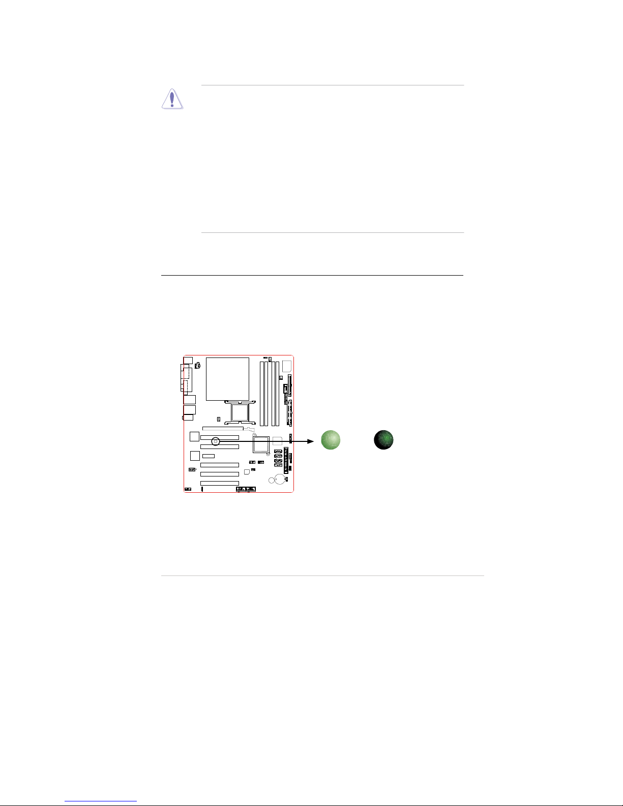
The motherboard comes with a standby power LED that lights up
that the system is ON, in sleep mode, or in soft-off mode. This is a reminder
that you should shut down the system and unplug the power cable before
removing or plugging in any motherboard component. The illustration below
shows the location of the onboard LED.
to
indic
Onboard LED
ON
Standby
Power
SB_PWR
OFF
Powered
Off

1.5 Motherboard over
vie
w
e
1.5.1 Placem
ent d
irection
in
e
1.5.2 Screw holes
the
towards
1-6 Chapter 1: Product introduction
Before you install the motherboard, study the configuration of your chassis to
ensure that the motherboard fits into it.
When installing the motherboard, make sure that you place it into the chassis
the correct orientation. The edge with external ports goes to the rear part of th
chassis as indicated in the image below.
Make sure to unplug the power cord before installing or removing the
motherboard. Failure to do so can cause you physical injury and damag
motherboard components.
Place ten (10) screws into the holes indicated by circles to secure
motherboard to the chassis.
Do not overtighten the screws! Doing so can damage the motherboard.
Place this side
the rear of the chassis
1
.5.
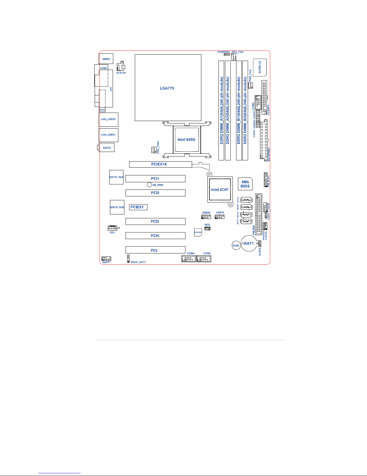
3 EAX
-945G Motherboard layout
EAX-945G / EAX-945G2
1-7
5

1.5.
4 EAX
-945G2 Motherboard layou
t
1-8 Chapter 1: Product introduction
C
C
O
O
M
M
2
2
R
R
S
S
C
C
O
O
M
M
2
2
R
R
S
S
4
4
C
C
O
O
M
M
2
2
R
R
S
S
3
33
S
R
2
M
O
C
4
S
R
2
M
O
C
S
R
2
M
O
C
5
1.6 Central Processing Unit (CPU)
n
1.6.1 Inst
alling
the CP
U
EAX-945G / EAX-945G2
1-9
The motherboard comes with a surface mount LGA775 socket designed for the
®
Intel
Pentium
package.
®
D / Pentium
®
4 / Celeron
®
/ Core™2 Duo processor in the 775-la
®
Your boxed Intel
•
LGA775 processor package should come with installation instructions for
the CPU, fan and heatsink assembly. If the instructions in this section do
not match the CPU documentation, follow the latter.
Upon purchase of the motherboard, make sure that the PnP cap is on the
•
socket and the socket pins are not bent. Contact your retailer immediately
if the PnP cap is missing, or if you see any damage to the PnP cap/socket
pins/motherboard components. Avalue will shoulder the cost of
repair only if the damage is shipment/transit-related.
Keep the cap after installing the motherboard. Avalue will process
•
Return Merchandise Authorization (RMA) requests only if the motherboard
comes with the cap on the LGA775 socket.
The product warranty does not cover damage to the socket pins resulting
•
from incorrect CPU installation/removal, or misplacement/loss/incorrect
removal of the PnP cap.
Pentium
®
D / Pentium
®
4 / Celeron
®
/ Core™2 Duo
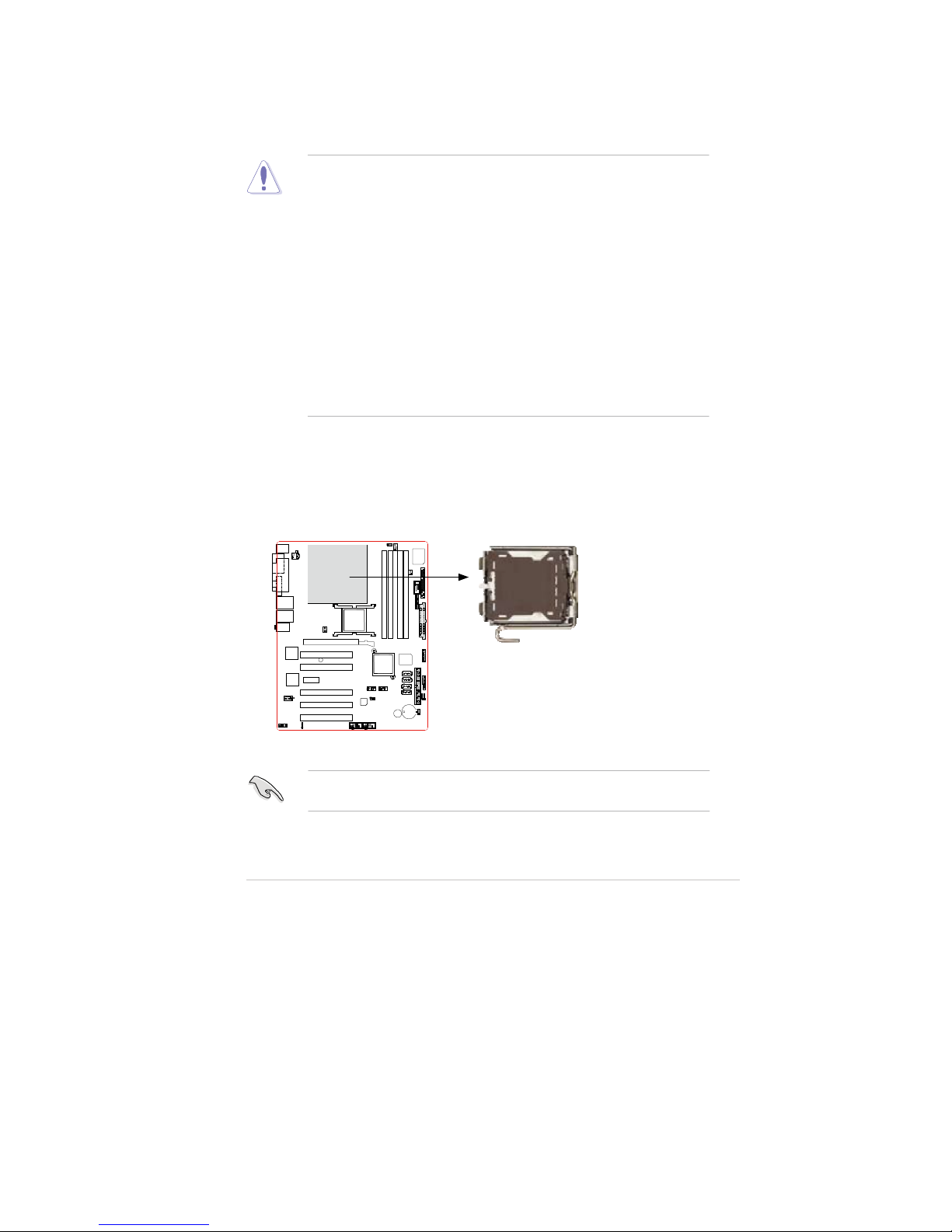
To install a CPU:
1. Locate the CPU socket on the motherboard.
CPU
Socket
775
Before installing the CPU, make sure that the socket box is facing towards you
and the load lever is on your left.
 Loading...