


AFSAD12111
Atwood AFSAD12111, AFSAD12121, AFSD16111, AFSD12121, AFSD20111 Instruction Manual
...
1
Literature number 31970
hydro flame™
AF Series Furnaces Models
AFSAD12111, AFSAD12121
AFSD12111, AFSD12121
AFSD16111, AFSD16121
AFSD20111, AFSD20121
Technical Installation Manual
1120 North Main Street • Elkhart, IN 46514
USA & Canada : 1-866-869-3118
Internet: http://www.atwoodmobile.com
English, Français (et Canada)
WARNING
Installation of this appliance must be made in accordance with the written
instructions provided in this manual. No agent, representative or
employee of Atwood or other person has the authority to change, modify
or waive and provision of the instructions contained in this manual.
WARNING
Avoid possible injury or death
Improper installation, adjustment, alteration, service or maintenance can
cause property damage, personal injury or loss of life. Refer to the
installation instructions and/or owner’s manual provided with this
appliance. A qualified installer, service agency or the gas supplier must
perform installation and service.
CRITICAL INSTALLATION WARNINGS
DO NOT install furnace on material that restricts return air, like carpet or
any soft material such as vinyl.
DO NOT install furnace where clearance to combustibles cannot be
maintained.
DO NOT modify furnace in any way.
DO NOT alter furnace for a positive grounding system.
DO NOT hi pot furnace unless electronic ignition system (circuit board)
has been disconnected.
DO NOT use battery charger to supply power to DC model furnace
even when testing.
DO NOT use 120-volt AC current with DC models.
DO NOT use furnace cabinet area as a storage compartment.
DO NOT vent furnace with venting system serving another appliance.
DO NOT vent furnace to an outside enclosed porch area.
DO NOT use for temporary heating of buildings or structures under
construction.
Protect building materials from degrading from flue gas exhaust.
Protect furnace electrical components from water.
Compartments must be closed when operating unit.
Should the gas supply fail to shut off during operation or overheating
occurs, shut the gas valve off to the furnace before shutting off electrical
supply.
DO NOT use this furnace if any part has been under water.
CAUTION
PERSONAL INJURY
All sheet metal edges are sharp care should be taken when handling or
brushing up against them.
FOR YOUR SAFETY
Do not store or use gasoline or other flammable vapors and liquids in the
vicinity of this or any other appliance.
WARNING
Be sure the furnace and all ignition systems are “off” during any type of
refueling and while vehicle is in motion or being towed.
TO THE INSTALLER: LEAVE THIS MANUAL WITH
THE APPLIANCE.
TO THE CONSUMER: RETAIN THIS MANUAL FOR
FUTURE REFERENCE.
SAFETY ALERT SYMBOLS
Safety Symbols alerting you to potential personal safety
hazards obey all safety messages following these symbols
WARNING
Avoid possible injury or
death
CAUTION
Avoid possible injury
and/or property damage
WARNING
FIRE OR EXPLOSION
If the information in this manual is not followed exactly, a
fire or explosion may result causing property damage,
personal injury or loss of life.
FOR YOUR SAFETY
WHAT TO DO IF YOU SMELL GAS:
Extinguish any open flame.
Evacuate all persons from the vehicle.
Shut off the gas supply at the gas container or
source.
Do not touch any electrical switch, or use any
phone or radio in the vehicle.
Do not start the vehicle’s engine or electric
generator.
Contact the nearest gas supplier or qualified
service technician for repairs.
If you cannot reach a gas supplier or qualified
service technician, contact the nearest fire
department.
Do not turn on the gas supply until the gas
leak(s) has been repaired.
A qualified Service Technician
Service Center or gas supplier must perform
installation and service.
This instruction manual is for use by an authorized service technician
to install an Atwood – hydro flame™ furnace. Should you require
further information, contact your dealer or Atwood Mobile Products
LLC.
This furnace design has been certified for installation in recreation
vehicles as a MSP Category III furnace. Follow this installation
instruction to insure safe operation of the furnace. Failure to install
furnace according to this installation instruction nullifies the furnace
warranty.
Effective 5/2014
2
WARNING
CARBON MONOXIDE POISONING
Properly seal vent assembly to prevent carbon monoxide from entering
coach.
DO NOT draw combustion air from living area.
DO NOT vent exhaust air into the living area or an enclosed porch.
WARNING
CARBON MONOXIDE POISONING
Furnace must be installed and vented to these instructions.
Improper installation, adjustment, alteration, service or
maintenance can cause injury or property damage.
Improper installation location may cause furnace to produce negative
pressure, affecting combustion air or venting of other appliances.
WARNING
CARBON MONOXIDE POISONING
Properly seal door to prevent carbon monoxide from entering
coach.
Properly adjust draft cap to prevent carbon monoxide from
entering coach.
Model Nomenclature
AF M D
25 1 1 1 A
Atwood
Furnace
Cabinet
Size
Voltage
Input
Btu/hr
Gas
Type
Gas
Fitting
or Style
Valve
Model
Rev
S=small
D=12
VDC
12K
16K
1=LP
1=Inside
Door
1
Single
A
M=medium
A=120
VAC
20K
25K
2=LP/NAT
2=Outside
LD
2 Stage
L=large
30K
35K
SA=small
low amp
40K
Models #
AFSD12111
AFSD12121
AFSD16111
AFSD16121
AFSD20111
AFSd20121
AFSAD12111
AFSAD12121
Type of
Gas
LP/Propane
LP/Propane
LP/Propane
LP/Propane
BTU Input
12,000
16,000
18,000
12,000
BTU
Output
9,120
12,160
13,680
9,120
Duct Static
Pressure
0.10”WC
0.10”WC
0.10”WC
Non ducted
12 Volt
Amperage
(AMPS)
3.4
3.4
4.8
2.4
Power
Supply
(Volt DC)
12
12
12
12
Watts
41
41
56
34
Minimum
Return Air
35 in2
35 in2
35 in2
35 in
2
Models
AFSD12
AFSD16
AFSD20
AFSAD12
Side Ducting
2 Ducts
2 Ducts
2 Ducts
N/A
Front with Side
Ducting
1 or 2
Ducts
1 or 2
Ducts
1 or 2
Ducts
N/A
Front Only no
Side Ducts
Front
Front
Front
Front
Approx. Dim.
Height
Width
Depth
Weight
Casing
7”
12”
20”
Furnace 21 lbs
Boxed 24 lbs
Vent (LD)
4-5/8”
6-5/16”
1-1/6”
Door
9-3/4”
14-3/4”
1/2”
Interior Grill
12-1/2”
8-1/2”
1/2”
Trim Ring
10-1/8”
14-1/8”
1/8”
clearances
Top
Sides
Rear
Bottom (to
screw
heads)
Blower (side
opening)
Vertical /
Horizontal
1/2”
1/2”
1/2”
0”
36 sq. in.
SPECIFICATIONS
MODEL Table 1
(WC = WATER COLUMN)
DUCTING CONFIGURATION Table 2
DIMENSION Table 3
Contents
SPECIFICATIONS ................................................................... 2
MODEL Table 1 ............................................................................. 2
DUCTING CONFIGURATION Table 2 ........................................... 2
DIMENSION Table 3 ..................................................................... 2
MINIMUM CLEARANCE TO COMBUSTIBLES: Table 4 .............. 2
INSTALLATION AND SAFETY CODES.................................. 3
GENERAL FURNACE LOCATION AND INSTALLATIONS ... 3
FURNACE INSTALLATION ..................................................... 3
WALL CUTOUTS Table 5 ............................................................. 3
SMALL VENT INSTALLATION ................................................................ 3
STANDARD DOOR INSTALLATION ....................................................... 4
INTERIOR GRILL INSTALLATION .......................................................... 4
FLEXIBLE DUCTING SYSTEMS .............................................................. 5
PROPANE GAS CONNECTION .............................................. 5
ELECTRICAL CONNECTIONS ............................................... 5
THERMOSTAT INSTALLATION ............................................. 6
OPERATING INSTRUCTIONS ................................................ 6
WIRING AND LADDER DIAGRAM .......................................... 7
PART DRAWINGS & PART LISTS ......................................... 8
MINIMUM CLEARANCE TO COMBUSTIBLES: Table 4
Floorboards, walls & similar combustible building materials
must be provided the full length and width of the unit.
Spacing of 1/4” to ducting within 3 feet of furnace must be provided
unless UL listed wire bound vinyl ducts are used. All ducting material
must be rated for continuous use at minimum of 200°F.
Clearances are specifically for plywood or similar building materials
surrounding the furnace (i.e. Furnace should not be located under
furniture or in a closet space where clothing or other material could be
located).
Furnace efficiency rating is a thermal rating determined under
continuous operating conditions, independent of any installation.
Efficiency rate is given at 76% minimum; actual efficiency rating may
be higher.
Return air is supplied through openings or around the furnace. All
return air passages must be kept clear for furnace to function properly.
Refer to Minimum clearance to floorboards, walls & similar combustible
building material in Table 4.
The total unobstructed return air opening size must not be less than
specified in specification Table 1. Failure to meet minimum return air
requirements nullifies furnace warranty.
To install without adding the additional 16 sq. in. cutout on the blower
side supply the right side of unit (blower side) with 2” clearance full
length of the unit.
3
A B D
Small Vent (exterior)
- - 3-1/2” Dia.
Standard Door (exterior)
12-1/4”
max
7-1/4”
Max
Front Grill (interior cabinet)
11-0”
max
7-1/4”
max
Front Grill Trim Ring
(interior cabinet)
12-1/2”
max
8-3/4”
max
INSTALLATION AND SAFETY CODES
USA and Canada – follow all applicable state and local codes – in the
absence of local codes or regulations, refer to current standards of:
Recreation Vehicles ANSI A119.2/NFPA 501C
National Fuel Gas Code ANSI Z223.1 and/or CAN/CGA B149
Installation Codes
This furnace must be installed in accordance with the manufacturer’s
instructions and the manufactured Home Construction and Safety
Standard, Title 24 CFR, part 3280, or when such standard is not
applicable, the Standard for Manufactured Home Installations.
(Manufactured Home Sites, Communities and Set-Ups), ANSI A255.1
and/or CAN/CSA-Z240 MH Series M92 Canadian Standard for Mobile
Homes.”
ANSI A 255.1 and/or CAN/CSA-Z240.6.2 MH Series, Mobile Homes
Ground National Electrical Code ANSI/NFPA 70 and/or CSA C22.1,
Part 1
Park Trailers ANSI 119.5
GENERAL FURNACE LOCATION AND INSTALLATIONS
All models can be installed in either a horizontal or vertical mounting
position Horizontal installs must have the gas line positioned on top,
vertical installs must have the vent located at floor level and gas line on
the right side.
Always install furnace exhaust system through an exterior wall.
DO NOT install furnace near tilt-out rooms, slide-outs, doors or other
projection that could obstruct furnace exhaust.
Locate furnace near midpoint of coach for single furnace applications.
Installation must provide accessibility if any repairs are necessary to
the furnace. Failure to meet this requirement will create additional labor
costs that will be the responsibility of the installer.
DO NOT install vent in areas where projection or door openings come
within 6” of vent opening.
DO NOT install furnace in an area where wires, pipes or other objects
will interfere with installation or operation of furnace.
DO NOT install furnace on material that restricts return air, such as
directly on carpet, or soft material (like vinyl). If you must install furnace
on carpet or soft material, install furnace on cleats, or on a wood or
metal panel extending the full width and depth of furnace plus
minimum clearance to combustibles.
DO NOT use petroleum or citrus type cleaner on plastic parts, as
damage may occur.
NOTE: The exhaust temperature of this furnace could discolor or warp
some materials. You should verify that the material used on the coach
door, panel, or cover will not discolor or warp from the exhaust
temperature whenever any door, panel, or cover is in the open
position.
CAUTION: Due to the differences in vinyl siding, materials this
appliance should not be installed without first consulting with the
manufacturer of the siding or cutting the siding away from the area
around the appliance vent.
A gas-fired furnace for installation in a residential garage must be
installed so the burner(s) and the ignition source are located not less
than 18 in (457mm) above the floor and the furnace must be located or
protected to avoid physical damage by vehicles.
FURNACE INSTALLATION
The furnace should always be installed level (front to back, side to
side) to prevent water intrusion into the interior.
Set aside venting and outer door parts for installing on the outside of
coach.
NOTE to assure sufficient return air to circulating blower maintain
specified clearances see Table 4.
Units can be installed with or without the interior grill. If grill is not used
a minimum of 35 sq. in. of free return must be provided.
If units are installed using the small outside vent system access to the
inside of the coach must be provided directly in front of the unit to
remove for service suggested opening size 12-1/2” wide by 8-3/8”
height.
Remove knockouts from furnace and install two duct adapters for side
discharge by inserting back flange over casing and inserting tab into
square notch, then twist adapter 90°.
Insert furnace into cabinet opening and secure with two screws
through casing legs to floor. Units are secured by door or vent systems
through the coach sidewall.
Attach flexible ducting over duct adapters and secure. All flex ducting
requires rating of 200°F.
Run ducting to locations keeping bends and excess ducting to a
minimum and secure to registers.
Connect wiring to furnace. See wiring connection section.
Connect gas line to top, side or rear of furnace. See gas connection
Figure 6.
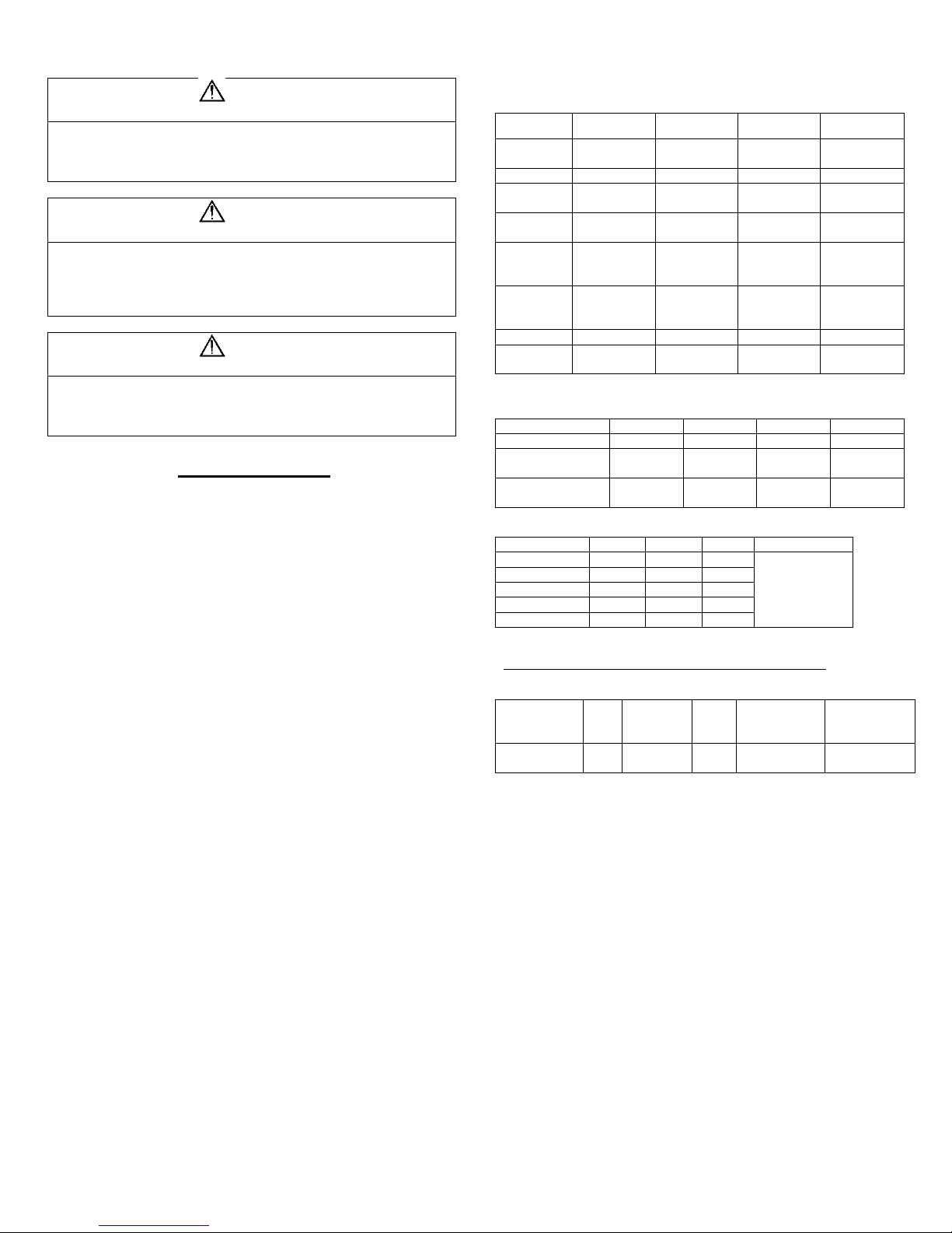
1. Cut the required exterior wall opening for your venting system see
Figure 1.
2. Configure furnace for ducting option to be used refer to duct
configurations Table 2.
3. Install furnace into opening and attach ducting to adapters.
4. Make gas and electrical connections, to the units.
5. See door or vent installation below on how to complete the installation.
SIDEWALL CUTOUT
* Door system exterior wall thickness 0” to 2-1/2”.
* Small vent system 0” to 2-1/2”.
WALL CUTOUTS Table 5
Figure 1
DO NOT oversize hole – over sizing can result in water leakage.
Zero clearance around air intake cutout for best sealing condition.
SMALL VENT INSTALLATION
4
Models
Required Discharge Area
AFSDA
FRONT GRILL ONLY
AFSD
24 in2
Figure 2
To prevent moisture from entering inside of coach, apply RTV
type sealant to the back of the bezel flange of the vent part.
Vents are designed to allow water drainage when installed
correctly.
Vents are design to allow for different wall thickness up to a
maximum of 2-1/2”
1. Locate vent hole cutout as called out in Figure 2.
2. Drill 3-1/2” diameter hole through sidewall of coach maximum wall
thickness 2-1/2”.
3. Remove vent and vent ring from furnace.
4. Insert furnace from backside of wall, lining up hole in wall with
vent in furnace.
5. Apply sealant to back of vent ring.
6. Install vent assembly with HOT at top on horizontal installations
and HOT on right side for vertical installations. Vent ring must slip
inside combustion air intake tube. Secure to wall with 2 screws
not provided.
7. Vent assembly must maintain minimum overlap of 1-1/4” on
exhaust tube and 1/2” minimum on combustion air tube. DO NOT
exceed maximum wall thickness.
8. Secure furnace to floor with legs provided on back of casing. For
vertical units casing legs can be positioned for placement to
secure furnace
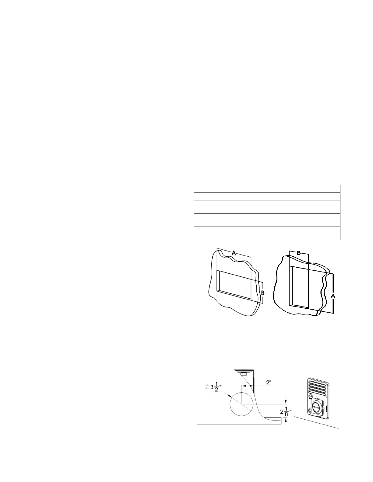
STANDARD DOOR INSTALLATION
Figure 3
To prevent moisture from entering inside of coach, apply RTV
type sealant to all sealing areas.
The door bezel must fit tightly, to prevent water leakage.
Doors are designed to allow water drainage in either horizontal or
vertical installations. Proper location of vent assembly is important
for proper exhausting of fumes and proper function of furnace.
1. Cut hole opening as shown in Figure 3 in location of side wall
were unit will be installed.
2. Apply RTV type sealant to entire back flange of bezel creating a
sealing area.
3. Pull furnace forward through cutout about a 1” inch, slip bezel
around casing, and flush inner flange with casing.
4. Secure bezel to furnace casing with 6 screws.
5. Push furnace and bezel back tight against side wall and secure
with 14 screws.
6. When installing screws DO NOT deform bezel.
7. Connect the gas line to the valve and push the gas line plug into
casing opening.
8. Remove excess sealant from around bezel and visually inspect
bezel to make sure it is completely sealed.
9. Secure furnace to floor with mounting legs provided.
10. Fasten door and vent with 6 screws provided.
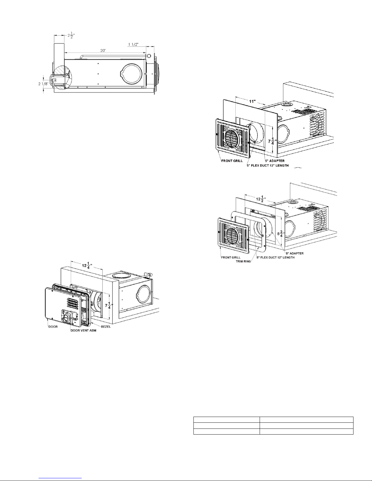
INTERIOR GRILL INSTALLATION
Figure 4
Figure 5
To install grill cut an 11” x 7.25” hole into the cabinet for a non-
removable furnace installation. See Figure 4
To install grill as an access to remove furnace cut a 12-1/2” x 8-3/4”
hole into the cabinet from the floor up you must also purchase a trim
ring for this installation. See Figure 5
Interior grill supplies return air and heated air necessary for AFSA
models and must be used. All other AFS models this grill is an option.
Discharge air from the round center louver can be direct 360° by tuning
louver.
1. Locate furnace and cut opening in outside wall as shown in figure 1.
2. To install grill for front discharge remove the knockout from the rear of
the casing and attached the 5” duct adapter.
3. Fasten 5” ducting to the adapter and to the back of the interior grill and
secure.
4. On installation with 1” or less space between furnace and cabinet face
grill can be inserting into the adapter ring to complete the connection.
5. Secure grill to cabinet by fastening with two screws through mounting
holes or if optional trim ring secure first with four screws to the cabinet
then the grill to the trim ring.
6. Vertical installation cutout and space see Table 5 for dimensions.
DUCTING OPTIONS
REQUIRED MINIMUM DISCHARGE
5
12,000
16,000
20,000
1650*
1650*
1800*
WARNING
FIRE OR EXPLOSION
Never check for leaks with an open flame. Turn on the gas and apply
soapy water to all joints to see if bubbles are formed.
WARNING
INJURY OR PROPERTY DAMAGE
Label all wires before disconnecting for servicing. Wiring errors can
cause improper and dangerous operation. Verify proper operation
after servicing.
Disconnect electrical power before servicing.
CAUTION
PROPERTY DAMAGE
This connection is for low-voltage battery or direct current only. Do not
connect to 120 or 240 volts AC.
Figure 6
Proper duct installation is critical to operation of furnace. When
installing ducts, use materials rated for continuous use at 200°F.
See minimum clearance to floorboards, walls & similar combustible
building materials.
Each 4-inch duct opening provides 12 in2 of discharge area. Minimum
for this furnace is 24 in2. If closeable registers or a 2” duct is used unit
must be provide with a front grill system.
Ducting in dead air space with no return air, such as holding tank
areas, does not count toward achieving minimum discharge
requirements.
Adjust ducting installation to obtain air rise of 100°F-130°F for optimum
performance.
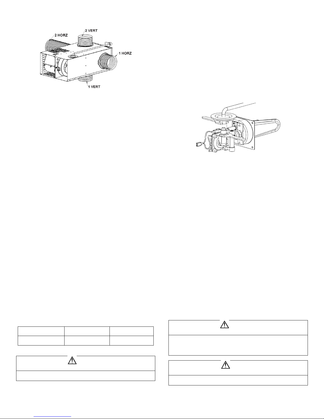
FLEXIBLE DUCTING SYSTEMS
When designing flexible duct systems:
Follow ducting configuration show in Table 2.
Avoid sharp bends or crushed ducts.
Stretch all ducts and run them directly to outlets, keeping quantity and
angles of bends to a minimum.
1. Remove knockout plate from desired outlets. See Figure 6. If both 4”
outlets are not being used leave in place, if removed a cover plate can
be purchased.
2. Attach a duct adapter by inserting flange over casing hole, locking the
tab into casing slot and turning adapter 90°.
3. Attach and secure four-inch flexible duct to adapter(s).
4. Run duct(s) to desired location within RV, secure to register(s).
AIR FLOW CHECK
Appliances are tested to a temperature rise as specified on the Rating
Plate. After installation of the furnace and duct system is completed,
adjustments to be made to obtain a temperature rise as specified on
the Rating Plate.
The table below is used as reference to maintain maximum operation
of the appliance. If checking temperature rise is not possible, air flow
measurements at each registers added together and divide by total
registers will give you air flow reading. This reading should not be less
than the minimum in the table under your BTU appliance size.
If readings are below table values, air flow can be improved by adding
ductwork. Check to make sure restrictions in the system are not
present.
PROPANE GAS CONNECTION
Propane Gas Pressure Test
The furnace and any individual shut-off valve must be
disconnected from gas supply piping system during and
pressure testing of system at test pressures of more than 1//2”
PSI.
Before furnace is, connected piping systems are to be tested to
be leak free. The test must maintain air pressure of a least 6”
of mercury or 3 PSI for at least 10 minutes.
The entire piping system is to be maintained for a pressure of
10” to 13” W.C. when all appliances are in operation. Test gas
connections for leakage with soapy water or a leak test
solution.
Figure 7
1. Connect gas line to the fitting located on top right side of furnace or if is
supplied with an extended manifold at the rear of the furnace.
2. Be sure all male pipe threads, other than flare fittings, are treated with
a sealing compound resistant to the action of propane (LP) gas. DO
NOT put sealing compound on flare fittings.
3. Use two wrenches to hold nut when tightening gas lines. DO NOT twist
valve assembly. See Figure 7.
A 1/8” N.P.T. plug is accessible for test gauge connection on gas valve
assembly for pressure testing.
A 3/8” flared fitting connection provided at gas control valve inlet for
gas supply connection to furnace. The gas supply line of the furnace
must be of adequate size to provide 11” W.C. gas pressure. This
pressure to be maintained under maximum flow conditions with all gas
appliances in operation.
If local codes allow the use of a flexible gas appliance connector,
always use a new listed connector. Do not use a connector, which has
previously serviced another gas appliance.
1. Remove grommet plug from furnace.
2. Insert gas line through grommet plug (DO NOT CUT).
3. Connect gas line inside furnace casing immediately ahead of gas
control valve.
4. Connect gas line to brass fitting located on top or right side of
furnace.
5. Some models will have fittings at the rear outside of the casing.
6. Use two wrenches to hold brass fitting and flare nut when
tightening gas line to brass fitting. DO NOT twist valve assembly
ELECTRICAL CONNECTIONS
*FPM= feet per minute reading

6
AMPS 3 4 5 6 7 8 9 10
15
Gage
Max. Length of SAE conductor (in feet) from source to
device
18
57
43
34
29
25
21
19
17
11
16
87
65
52
43
37
33
29
26
17
WARNING
FIRE OR EXPLOSION
Do not operate furnace while vehicle is in motion or being
towed
DIAGNOSTICS CHART
FAULT
LED INDICATION
LOCKOUT
Internal Circuit Board
Failure
Steady On, No Flashing
Hard
Limit Switch/Airflow
Problems
1-Flash With 3-Second
Pause
Soft
Flame Sense Fault
2-Flashes With 3-Second
Pause
Hard
Ignition Lockout Fault
3-Flashes With 3-Second
Pause
Soft (after 1 hr)
POWER SUPPLY
Atwood Mobile Products LLC highly recommends the use of an
electronic (solid-state) converter with clean power output. This will
assure extended life of the electronic controls and motor beyond
typical linear converter applications.
Conductor Sizing Table 6
– Maximum 10% Voltage Drop – (12 VDC)
Current draw (AMPS)
This furnace designed for negative ground 12 volts DC only. DO NOT
attempt to alter furnace for a positive ground system or connect the
furnace directly to 120 volts, AC. Damage to furnace components will
occur and warranty will be voided.
Use a minimum of 18 GA wire to minimize voltage drop. Furnace must
be installed so electrical components are protected from water. To
make electrical connections see wiring diagrams.
For best furnace performance when power supply is from a converter
equipped with a charging port, wire converter to furnace parallel with
battery. This provides consistent voltage to furnace, increasing
component life, filtering power surges and AC spikes.
All units are supplied with a power switch which when turned off during
servicing will remove power through furnace wiring. Switch must be in
the ON position for furnace to operate.
Route wiring to the furnace.
Connect red wire to positive +12VDC of power supply.
Connect black wire to ground of power supply.
Connect Thermostat +12 VDC blue wire to power supply using 22-18
GA stranded wire.
Connect Thermostat blue wire to the thermostat lead using minimum
22-18 GA stranded wire.
All wiring shall be installed so the electrical components are protected
from water.
THERMOSTAT INSTALLATION
Thermostats not supplied. Purchase a thermostat rated for 12 VDC or
24 VAC, Minimum 1 AMP rating see Atwood parts list for thermostat
numbers.
Be sure all electrical power to the furnace is disconnected.
The thermostats are very sensitive, HANDLE WITH CARE AT ALL
TIMES.
Pick a dry area where air circulation is good.
Do not install the thermostat where there are unusual heating
conditions: such as direct sunlight, heat producing appliances
(television, radio, wall lamp, etc.) or a furnace or air conditioner output
registers.
Locate thermostat 48” to 54” above main living area floor on an
INTERIOR wall when possible
EXTERIOR wall location must have a 3/4” spacer between thermostat
and exterior wall.
Follow manufacture’s installation instructions provided with thermostat.
OPERATING INSTRUCTIONS
Stop! Read Users Information Manual supplied with
furnace.
1. Turn the manual valve (if so equipped) or the valve at the outside LP
tank to the “OFF”” position. Do NOT force. NOTE: This furnace is
equipped with a valve shut-off switch with switch in “OFF” position.
Gas will not flow to burner nor will the furnace operate. Turn switch to
“ON” position.
2. Set thermostat above room temperature to begin blower operation. A
slight delay will occur before the blower comes on. Allow blower to run
for 1 minute for combustion chamber purge cycle. If blower does not
come on or stops before ignition cycle, go to shut down and contact
your dealer or a local recreational vehicle service agency.
3. After 1 minute, move thermostat lever below room temperature. Blower
will remain on. Wait approximately 2 minutes for blower to go off.
4. Open manual shut-off valve (if so equipped) or the valve at the outside
LP tank. Correct operation characteristics depend on the valve being
positioned fully open. Never attempt to operate with a valve partially
closed.
5. Set thermostat lever to desired setting. If set above room temperature,
blower will come on.
6. Allow 30 seconds for main burner to light after blower comes on. This
furnace is equipped with an ignition device that automatically lights the
burner. DO NOT try to light the burner by hand.
7. If burner does not light, repeat Steps 1 through six.
8. If after three (3) attempts with no ignition, go to shut down and contact
your dealer or a local recreational vehicle service agency. Do not
continue to cycle furnace through thermostat in an attempt to get
ignition.
TO SHUT DOWN
1. Set the thermostat to lowest setting, then move lever to “OFF” position.
2. Turn manual shut off valve (if so equipped) to the “OFF” position. Do
not force.
SYSTEM CHECKS
PROPANE GAS PRESSURE TEST
The furnace and any individual shut-off valve must be disconnected
from gas supply piping system during any pressure testing of system at
test pressures of more than 1/2” PSI.
Before furnace is connected, piping systems must be tested to be leak
free. The test must maintain air pressure of a least 6” of mercury or 3”
PSI for at least 10 minutes.
The entire piping system must be maintained within a range of 10 to
14” WC when all appliances are in operation. Test gas connections for
leakage with a leak test solution.
Ignition control diagnostic codes
The following charts give the diagnostic codes given by the ignition
control when faults are present.
A soft lockout is a timed condition that will make additional
attempts to correct the problem. A hard lookout requires resetting
of the thermostat or turning the power switch off, then back on.
Standard 3 tries for Ignition Controls
During initial firing of this furnace, a burn-off of excess oils remaining
from manufacturing process may cause smoking or fumes for 5-10
minutes.
NOTE: if furnace should lock out, the blower will go off in 90 seconds
and remain off until unit is reset by reactivating the thermostat.
 Loading...