


USER MANUAL
BULLET NETWORK CAMERA
Please read this manual thoroughly before use and keep it handy for future reference.

WARNING
TO REDUCE THE RISK OF FIRE OR ELECTRIC SHOCK, DO NOT EXPOSE THIS PRODUCT TO RAIN OR MOISTURE. DO NOT INSERT ANY METALLIC OBJECT THROUGH THE VENTILATION GRILLS OR OTHER OPENNINGS ON THE EQUIPMENT.
CAUTION
CAUTION
RISK OF ELECTRIC SHOCK
DO NOT OPEN
WARNING: TO REDUCE THE RISK OF ELECTRIC SHOCK,
DO NOT REMOVE COVER (OR BACK).
NO USER-SERVICABLE PARTS INSIDE.
REFER SERVICING TO QUALIFIED SERVICE PERSONNEL
EXPLANATION OF GRAPHICAL SYMBOLS
The lightning flash with arrowhead symbol, within an equilateral triangle, is intended to alert the user to the presence of dangerous voltage within the products enclosure that may be of sufficient magnitude to constitute a risk of electric shock to persons.
The exclamation point within an equilateral triangle is intended to alert the user to the presence of important operating and maintenance (servicing) instructions in the literature accompanying the product.
2

FCC COMPLIANCE STATEMENT
This device complies with Part 15 of the FCC Rules. Operation is subject to the following two conditions: (1) this device may not cause harmful interference, and (2) this device must accept any interference received, including interference that may cause undesired operation.
FCC INFORMATION: This equipment has been tested and found to comply with the limits for a Class A digital device, pursuant to Part 15 of the FCC Rules. These limits are designed to provide reasonable protection against harmful interference when the equipment is operated in a commercial environment. This equipment generates, uses, and can radiate radio frequency energy and, if not installed and used in accordance with the instruction manual, may cause harmful interference to radio communications. Operation of this equipment in a residential area is likely to cause harmful interference in which case the user will be required to correct the interference at his own expense.
CAUTION: Changes or modifications not expressly approved by the party responsible for compliance could void the user’s authority to operate the equipment.
This Class A digital apparatus complies with Canadian ICES-003.
Cet appareil nume`rique de la classe A est conforme a´ la norme NMB-003 du Canada.
CE COMPLIANCE STATEMENT
WARNING
This is a Class A product. In a domestic environment this product may cause radio interference in which case the user may be required to take adequate measures.
CAUTION
RISK OF EXPLOSION IF BATTERY IS REPLACED BY AN INCORRECT TYPE. DISPOSE OF USED BATTERIES ACCORDING TO THE INSTRUCTIONS.
3

IMPORTANT SAFETY INSTRUCTIONS
1.Read these instructions.
2.Keep these instructions.
3.Heed all warnings.
4.Follow all instructions.
5.Do not use this apparatus near water.
6.Clean only with dry cloth.
7.Do not block any ventilation openings. Install in accordance with the manufacturer’s instructions.
8.Do not install near any heat sources such as radiators, heat registers, stoves, or other apparatus (including amplifiers) that produce heat.
9.Do not defeat the safety purpose of the polarized or grounding-type plug. A polarized plug has two blades with one wider than the other. A grounding type plug has two blades and a third grounding prong. The wide blade or the third prong is provided for your safety. If the provided plug does not fit into your outlet, consult an electrician for replacement of the obsolete outlet.
10.Protect the power cord from being walked on or pinched particularly at plugs, convenience receptacles, and the point where they exit from the apparatus.
11.Only use attachments/accessories specified by the manufacturer.
12.Use only with the cart, stand, tripod, bracket, or table specified by the manufacturer, or sold with the apparatus. When a cart is used, use caution when moving the cart/apparatus combination to avoid injury from tip-over.
13.Unplug this apparatus during lightning storms or when unused for long periods of time.
14.Refer all servicing to qualified service personnel. Servicing is required when the apparatus has been damaged in any way, such as power-supply cord or plug is damaged, liquid has been spilled or objects have fallen into the apparatus, the apparatus has been exposed to rain or moisture, does not operate normally, or has been dropped.
15.CAUTION : These servicing instructions are for use by qualified service personnel only. To reduce the risk of electric shock do not perform any servicing other than that contained in the operating instructions unless you are qualified to do so.
16.ITE is to be connected only to PoE networks without routing to the outside plant.
17.This product is intended to be supplied by a Listed Power Supply Unit marked “Class 2” or “LPS” and rated from 12 Vdc, 740 mA.
18.The wired LAN hub providing power over the Ethernet (PoE) in accordance with IEEE 802-3af shall be a UL Listed device with the output evaluated as a Limited Power Source as defined in UL60950-1.
19.Unit is intended for installation in a Network Environment 0 as defined in IEC TR 62102. As such, associated Ethernet wiring shall be limited to inside the building.
20.CAUTION : Risk of Explosion if Battery is replaced by an Incorrect Type. Dispose of Used Batteries According to the Instructions.
ATTENTION : II y a danger d’explosion s’il y a remplacement incorrect de la batterie. Remplacer uniquement avec une batterie du même type ou d’un type équivalent recommandé par le constructeur. Mettre au rebut les batteries usagées conformément aux instructions du fabricant.
4
Contents
1 |
Introduction |
6 |
||
|
1.1 |
Components |
6 |
|
|
1.2 |
Key Features |
7 |
|
2 |
Installation |
|
8 |
|
|
2.1 |
Overview |
8 |
|
|
2.2 |
Connection |
10 |
|
|
2.3 |
Resetting to the factory default settings |
11 |
|
|
2.4 |
Network Connection & IP assignment |
12 |
|
3 |
Operation |
|
13 |
|
|
3.1 |
Access from a browser |
13 |
|
|
3.2 |
Access from the internet |
14 |
|
|
3.3 |
Setting the admin password over a secure connection |
14 |
|
|
3.4 |
Live View Page |
15 |
|
|
3.5 |
Playback |
17 |
|
|
3.6 |
Network Camera Setup |
19 |
|
|
|
3.6.1 |
Basic Configuration |
19 |
|
|
3.6.2 |
Video & Image |
24 |
|
|
3.6.3 |
Audio |
33 |
|
|
3.6.4 |
Event |
34 |
|
|
3.6.5 |
System |
59 |
|
3.7 |
Help |
|
80 |
A |
Appendix |
|
81 |
|
|
A.1 |
Troubleshooting |
81 |
|
|
A.2 |
Alarm Connection |
82 |
|
|
A.3 |
Preventive Maintenance |
82 |
|
|
A.4 |
System Requirement for Web Browser |
83 |
|
|
A.5 |
General Performance Considerations |
83 |
|
|
A.6 |
Product Specification |
84 |
|
5
1 Introduction
The network camera supports the network service for a sensor image with progressive scan, which can be monitored on a real-time screen regardless of distances and locations. By using its dedicated program, many users are able to have an access to the network camera at once or a single user can monitor various network cameras at the same time. It also enables users to play, store and retrieve a monitoring image by using a PC. All the settings and real-time monitoring screens are also provided through an access to the web.
The network camera is fully featured for security surveillance and remote monitoring needs. It is based on the DSP compression chip, and makes it available on the network as real-time, full frame rate Motion JPEG, H.264 and H.265 video streams.
The alarm input and alarm output can be used to connect various third party devices, such as, door sensors and alarm bells.
1.1Components
This system comes with the following components;
Network Camera |
1 |
Installation Guide/CD |
1 |
Accessory Kit |
1 |
Note 1. Check your package to make sure that you received the complete system, including all components listed above.
Note 2. Adapter for DC 12V is not supplied.
6
1.2Key Features
•Brilliant video quality
The network camera offers the highly efficient H.265 or H.264 video compression, which drastically reduces bandwidth and storage requirements without compromising image quality. Motion JPEG is also supported for increased flexibility.
•Quad streams
The network camera can deliver f o u r video streams simultaneously using H.264/H.265 and Motion JPEG. This means that several video streams can be configured with different compression formats, resolutions and frame rates for different needs.
•Intelligent video capabilities
The network camera includes intelligent capabilities such as enhanced video motion detection. The network cameras external inputs and outputs can be connected to devices such as sensors and relays, enabling the system to react to alarms and activate lights or open/close doors.
•Improved security
The network camera logs all user access, and lists currently connected users. Also, its full frame rate video can be provided overHTTPS.
•PoE (Power over Ethernet)
This network camera can be powered through PoE (IEEE802.3af), which simplifies installation since only one cable is needed for carrying power, as well as video controls.
•ONVIF certificate
This is a global interface standard that makes it easier for end users, integrators, consultants, and manufacturers to take advantage of the possibilities offered by network video technology. ONVIF enables interoperability between different vendor products, increased flexibility, reduced cost, and future-proof systems.
•Micro-SD recording support
The network camera also supports a micro-SD memory slot for local recording with removable storage of type SDHC and SDXC.
•Audio support
The Network Camera also supports two-way audio.
7

2 Installation
For the operation of the network camera, it is necessary to connect a network cable for data transmission, power connection from power adapter. Depending on operation methods, it is possible to connect an alarm cable additionally. For its fixation on different locations, please consult with an installer.
2.1Overview
•Dimension
Dimensions Unit: mm
•Extension Cable
NO |
Item |
Description |
|
|
|
|
|
|
|
Ethernet, RJ-45 port compatible |
|
1 |
RJ-45 |
with 10/100Mbps PoE Modular Jack |
|
|
|
|
|
2 |
DC Jack |
Main Power, DC Jack, DC12V |
|
|
|||
|
|
|
|
|
AI: Alarm In |
|
|
3 |
G: GND |
Alarm input and output, 3pin terminal |
|
|
AO: Alarm Out |
||
|
|
||
|
|
|
|
4 |
MIC: Audio In |
Audio line input, 2pin terminal |
|
|
|||
G: GND |
|||
|
|
||
|
|
|
|
5 |
SPK: Audio Out |
Audio line output, 2pin terminal |
|
|
|||
G: GND |
|||
|
|
8

•Installing Camera
To mount the bullet camera, fix the base of the camera with the three screws provided in the accessory kit.
9
2.2Connection
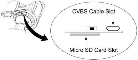
•Micro SD memory slot on the Bottom Board
Remove the cap at bottom of the camera to insert the SD memorycard.
•Connecting to the RJ-45
Connect a standard RJ-45 cable to the network port of the network camera. Generally a cross-over cable is used for directly connection to PC, while a direct cable is used for connection to a hub. You can also use a router featuring PoE (Power over Ethernet) to supply power to the camera.
•Connecting Alarms
AI(Alarm In): You can use external devices to signal the network camera to react on
events. Mechanical or electrical switches can be wired to the AI (Alarm In) and G (Ground) connectors.
G(Ground): Connect the ground side of the alarm input and/or alarm output to the G (Ground) connector.
AO(Alarm Out): The network camera can activate external devices such as buzzers or lights. Connect the device to the AO (Alarm Out) and G (Ground) connectors.
•Connecting the Power
Connect the power of 12VDC for the network camera. Connect the positive(+) pole to the ‘+’ position and the negative (-) pole to the ‘-’ position for the DC power.
–Be careful not to reverse the polarity when connecting the power cable.
–A router featuring PoE (Power over Ethernet) can also be used to supply power to the camera.
–For the power specifications, refer to the appendix, product specification.
–If PoE and 12 VDC are both applied, the camera will be supplied with power from PoE.
•Connecting Audio
Connect speaker to audio line output and external Mic to audio input line.
•Connecting Test Monitor Out(CVBS)
Connect 5pin micro USB test video cable(Optional) to check test video.
10
2.3Resetting to the factory default settings
To reset the network camera to the original factory settings, go to the Setup > System > Maintenance web page (described in “System > Maintenance” of User Manual) or use the Reset button on the network camera inside the bottom cap.
•Using the Reset button:
Follow the instructions below to reset the network camera to the factory default settings using the Reset button.
1)Switch off the network camera by disconnecting the power adapter.
2)Open the top cap.
3)Press and hold the Reset button with a straightened paperclip while reconnecting the power.
4)Keep the Reset button pressed about 5 or more seconds.
5)Release the Reset button.
6)The network camera resets to factory defaults and restarts after completing the factory reset.
7)Close the bottom cap tightly to ensure waterproof.
CAUTION: When performing a Factory Reset, you will lose any settings that have been saved. (Default IP 192.168.30.220)
11

2.4Network Connection & IP assignment
The camera supports the operation through the network. When a camera is first connected to the network, it is necessary to allocate an IP address to the device with the “SmartManager” utility on the CD. (Default IP 192.168.30.220)
1)Connect the network camera/device to the network and power up.
2)Start SmartManager utility (Start > All programs > SmartManager > SmartManager). The main window will display, and after a short while any network devices connected to the network will be displayed in the list.
3) Select the camera on the list and click right button of the mouse. You can see the pop-up menu as below.
4) Select Assign IP Address. The Assign IP window will display. Enter the required IP address.
NOTE: For more information, refer to the SmartManager User Manual.
12

3 Operation
The network camera can be used with Windows operating system and browsers. The recommended browsers are Internet Explorer, Safari, Firefox, Opera and Google Chrome with Windows.
NOTE: To view streaming video in Microsoft Internet Explorer, set your browser to allow ActiveX controls.
3.1Access from a browser
•Start a browser (Internet Explorer).
•Enter the IP address or host name of the network camera in the Location/Address field of your browser.
•You can see a starting page. Click Live View, Playback, or Setup to enter web page.
• The network cameras Live View page appears in your browser.
13

3.2Access from the internet
Once connected, the network camera is accessible on your local network (LAN). To access the network camera from the Internet you must configure your broadband router to allow incoming data traffic to the network camera. To do this, enable the NAT traversal feature, which will attempt to automatically configure the router to allow access to the network camera. This is enabled from Setup > System > Network > NAT. For more information, please see “ System > Network > NAT” of User Manual.
3.3Setting the admin password over a secure connection
To gain access to the product, the password for the default administrator user must be set. This is done in the “Admin Password” dialog, which is displayed when the network camera is accessed for the setup at the first time. Enter your admin name and password, set by the administrator.
NOTE: The default administrator user name and password is “admin”. If the password is lost, the network camera must be reset to the factory default settings. Please see “Resetting to the factory default settings.”
To prevent network eavesdropping when setting the admin password, this can be done via an encrypted HTTPS connection, which requires an HTTPS certificate (see NOTE below). To set the password via a standard HTTP connection, enter it directly in the first dialog shown below. To set the password via an encrypted HTTPS connection, please see “System
> Security > HTTPS” of User Manual.
NOTE: HTTPS (Hypertext Transfer Protocol over SSL) is a protocol used to encrypt the traffic between web browsers and servers. The HTTPS certificate controls the encrypted exchange of information.
14
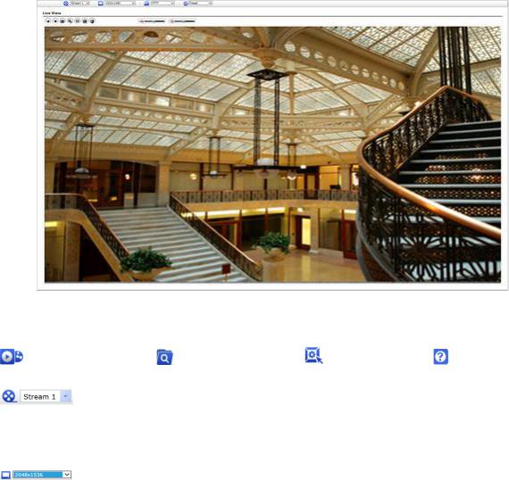
3.4Live View Page
The Live View page comes in several screen modes. Users are allowed to select the most suitable one out of those modes. Adjust the mode in accordance with your PC specifications and monitoring purposes.
1) General controls
Live View Page |
Playback Page |
Setup Page |
Help Page |
The video |
drop-down list allows |
you to select |
a customized or pre- |
programmed video stream on the Live View page. Stream profiles are configured under Setup > Basic Configuration > Video & Image. For more information, please see “Basic Configuration > Video & Image” of User Manual.
The resolution drop-down list allows you to select the most suitable one out of video resolutions to be displayed on Live View page.
 The protocol drop-down list allows you to select which combination of protocols and methods to use depending on your viewing requirements, and on the properties of your network.
2) Control toolbar
The live viewer toolbar is available in the web browser page only. It displays the following buttons:
 The Stop button stops the video stream being played. Pressing the key again toggles the start and stop. The Start button connects to the network camera or starts playing a video stream.
 The Pause button pauses the video stream being played.
 The Snapshot button takes a snapshot of the current image. The location where the image is saved can be specified.
15
 The Digital Zoom button activates a zoom-in or zoom-out function for video image on the live screen.
 The Full Screen button causes the video image to fill the entire screen area. No other windows will be visible. Press the ‘Esc’ button on the computer keyboard to cancel full screen view.
 The Manual Trigger button activates a pop-up window to manually start or stop the event.
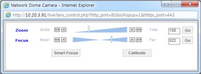
 The Lens Control button allows user to control Zoom and Focus manually. (This Icon appears for motorized lens model only.)
•Zoom: Click “ ” button to zoom out and click “
 ” button to zoom in. Or drag the bar to adjust the zoom. The focus is moved slightly after adjusting zoom; adjust the focus again, as necessary.
Focus: Click “ ” button to Near focus and click “
 ” button to Far focus. Or drag the bar to adjust the focus.
Smart Focus User can get automated focus here.
Calibrate Calibrate focus and zoom.
 The Smart Focus button activates smart focus function which set the focus to the optimum position. (This Icon appears for motorized lens model only.)
 The Relay Output button manually triggers relay out. (This Icon appears only if “Enable alarm out” is selected in “Event Out - Alarm Out”.)
 The Speaker button activates/deactivates externalspeaker.
 The Mic button activates/deactivates microphoneinput.
 Use this scale to control the volume of the speakers and microphones.
3) Video Streams
The network camera provides several images and video stream formats. Your requirements and the properties of your network will determine the type you use.
The Live View page in the network camera provides access to H.264, H.265 and Motion JPEG video streams, and to the list of available video streams. Other applications and clients can also access these video streams/images directly, without going via the Live View page.
16

3.5Playback
The Playback window contains a list of recordings made to the memory card. It shows each recording’s start time, length, the event type used to start the recording, calendar and time slice bar indicates if the recording is existed or not.
The description of playback window follows.
1) Video Screen
You can see the video screen when playing the video clip in the Micro SD memory.
2) Playback Buttons
To view a recording data in the SD local storage, select it from the list and click the Playback buttons.
 Go to the first: go to the beginning of the video clip.
 Fast backward play: fast play backward of the video clip.
 Backward play: play backward of the video clip.
 Step backward play: go back one frame of the video clip.
  Pause: pause playback of the video clip.
 Step forward play: go forward one frame of the video clip.
  Forward Play: play forward the video clip.
 Fast forward play: play fast forward of the video clip.
  Go to the last: go to the end of the video clip.
 Clip copy: copy the video clip.
  Zoom In: zoom in the video clip.
 Full Screen: display full screen of the video.
17
3) Time Chart
Display an hour-based search screen for the chosen date. If there is recording data, a blue section will be displayed on a 24-hour basis. If you select a particular hour in the chart, a yellow square on the hour will bedisplayed.
4) Speaker Control Bar
Use this scale to control the volume of thespeakers.
5) Search Calendar
Search results from the SD local storage in the network camera connected are displayed monthly. If there is a recorded data for a particular date, a blue square on the date will be displayed. If you select a particular date in the calendar, a yellow square on the date will be displayed.
6) Play Time
Displays time of the video playing.
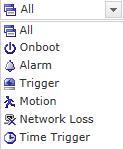
7) Event Search Window
Select a search option in the drop-down list and click GO button. You can also enter the time period for searching. If you click Start Date or End Date zone, displays Search Calendar.
8) Event List Window
Event List displays the event(s) that were recorded in the SD local storage. Select a list and click the play button. The video clip will be played.
18

3.6Network Camera Setup
This section describes how to configure the network camera.
Administrator has unrestricted access to all the Setup tools, whereas Operators have access to the settings of Basic Configuration, which are Live View, Video & Image, Audio, Event and System.
You can configure the network camera by clicking Setup either in the first connection page or the top second-right button of the Live View page. Accessing the network camera from a computer for the first time opens the Admin Password dialog box. Enter your administrator or operator id and password to get into setuppage.
NOTE: If the password is lost, the network camera must be reset to the factory default settings. Please see “Resetting to the Factory Default Setting”.
3.6.1 Basic Configuration
You can see the device information in this information page.
19

1) Users
User access control is enabled by default. The administrator can set up other users, by giving user names and passwords. It is also possible to allow anonymous viewer login, which means that anybody may access the Live View page, as described below:
The user list displays the authorized users and user groups (levels):
User Group |
Authority |
|
Guest |
Provides the lowest level of access, which only allows access |
|
to the Live View page. |
|
|
|
|
|
|
|
|
|
An operator can view the Live View page, create and modify |
|
Operator |
events, and adjust certain other settings. Operators have no |
|
|
access to System Options. |
|
|
|
|
Administrator |
An administrator has unrestricted access to the Setup tools |
|
and can determine the registration of all other users. |
|
|
|
|
|
|
|
|
Please refer to “ System 2) Security Users” for more details about User setup. |
||
20
2) Network
The network camera supports both IP version 4 and IP version 6. Both versions may be enabled simultaneously, and at least one version must always be enabled. When using IPv4, the IP address for the network camera can be set automatically via DHCP, or a static IP address can be set manually. If IPv6 is enabled, the network camera receives an IP address according to the configuration in the network router. There is also an option of using the Internet Dynamic DNS Service. For more information on setting the network, please see “System > Network > Basic”.
•Obtain IP address via DHCP: Dynamic Host Configuration Protocol (DHCP) is a protocol that lets network administrators centrally manage and automate the assignment of IP addresses on a network. DHCP is enabled by default. Although a DHCP server is mostly used to set an IP address dynamically, it is also possible to use it to set a
static, known IP address for a particular MAC address.
•Use the following IP address: To use a static IP address for the network camera, check the radio button and then make the following settings:
–IP address: Specify a unique IP address for your network camera.
–Subnet mask: Specify the mask for the subnet the network camera is located on.
–Default router: Specify the IP address of the default router (gateway) used for connecting devices attached to different networks and network segments.
NOTES:
1.DHCP should only be enabled if using dynamic IP address notification, or if your DHCP server can update a DNS server, which then allows you to access the network camera by name (host name). If DHCP is enabled and you cannot access the unit, you may have to reset it to the factory default settings and then perform the installation again.
2.The ARP/Ping service is automatically disabled two minutes after the unit is started, or as soon as an IP address is set.
3.Pinging the unit is still possible when this service is disabled.
Please refer to “System > Network > Basic” for more details about Network setup.
21
3) Video & Image
User can setup and change setting of individual video stream in thispage.
Please refer to “Video & Image > Basic” for more details about Video & Image setup.
22
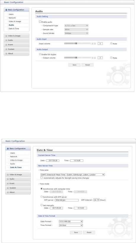
4) Audio
The network camera can transmit audio to other clients using an external microphone and can play audio received from other clients by attaching a speaker. User can setup and change setting of Audio in this page.
Please refer to “Audio” for more details about Audio setup.
5) Date & Time
User can set time directly or assign time server to get the current time, as well as determine Date & Time format in this page.
Please refer to “System > Date & Time” for more details about Date & Time setup.
23

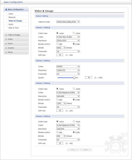
3.6.2Video & Image
1)Basic
•Sensor Setting:
–Capture mode: User can select sensor capture mode between 1920x1080(2MP) /2592x1520(4MP) and NTSC/PAL (Some models are fixed to NTSC or PAL).
•Stream 1 Setting:
–Codec: The codec supported in Stream 1 is H.264 and H.265
There are 3 pre-programmed stream profiles available for quick set-up. Choose the form of video encoding you wish to use from the drop-down list:
·H.264 High Profile:
Primary profile for broadcast and disc storage applications, particularly for highdefinition television applications (for example, this is the profile adopted by the Bluray Disc storage format and the DVB HDTV broadcast service).
·H.264/H.265 Main Profile:
Primary profile for low-cost applications that require additional error robustness, this profile is used rarely in videoconferencing and mobile applications; it does add additional error resilience tools to the Constrained Baseline Profile. The importance of this profile is fading after the Constrained Baseline Profile has been defined.
·H.264 Baseline Profile:
Originally intended as the mainstream consumer profile for broadcast and storage
24
applications, the importance of this profile faded when the High Profile was developed for those applications.
– Resolution:
This enables users to determine a basic screen size when having an access through the Web Browser or PC program. The screen size control comes in several modes. Users can change the selected screen size anytime while monitoring the screen on a real-time basis.
–Bitrate control:
The bit rate can be set as Constrained Bit Rate (CBR) or Constrained Variable Bit Rate (CVBR). Limiting the maximum bit rate helps control the bandwidth used by the H.264 o r H . 2 6 5 video stream. Leaving the Maximum bit rate as unlimited maintains consistently good image quality but increases bandwidth usage when there is more activity in the image. Limiting the bit rate to a defined value prevents excessive bandwidth usage, but images are degraded when the limit is exceeded.
·CBR: Constrained bitrate.
·CVBR: VBR with maximum bitrate which is set in Bitrate.
–Bitrate: Maximum bitrate for CBR in the range of 100kbps 10Mbps.
–Frame rate:
Upon the real-time play, users should select a frame refresh rate per second. If the rate is high, the image will become smooth. On the other hand, if the rate is low, the image will not be natural but it can reduce a network load.
–GOP size:
Select the GOP (Group of Picture) size. If users want to have a high quality of fast image one by one, please decrease the value. For the purpose of general monitoring, please do not change a basic value. Such act may cause a problem to the system
performance. For the details of GOP setting, please contact the service center.
•Stream 2 Setting:
Sometimes the image size is large due to low light or complex scenery. Adjusting the
frame rate and quality helps to control the bandwidth and storage used by the Motion JPEG video stream in these situations. Limiting the frame rate and quality optimizes bandwidth and storage usage, but may give poor image quality. To prevent increased bandwidth and storage usage, the Resolution, Frame rate, and Frame Quality should be set to an optimal value.
–MJPEG Resolution: Same as the stream 1 setting.
–MJPEG Frame rate: Same as the stream 1 setting.
–MJPEG Quality: Select the picture quality. If users want to have a high quality of fast image one by one, please decrease the value. For the purpose of general monitoring, please do not change a basic value. Such act may cause a problem to the system performance.
•Stream 3, Stream4 Setting: Same as the Stream 1 settings.
When the settings are complete, click Save button to save the settings, or click Reset button to clear all of the information you entered without saving it.
25

2) Privacy Masking
The privacy masking function allows you to mask parts of the video image to be transmitted. You can set up to eight privacy masks.
The privacy masks are configured by Mask windows. Each window can be selected by clicking with the mouse. It is also possible to resize or delete, or move the window, by selecting the appropriate window at the mouse menu on the video screen.
To create a mask window, follow steps:
1.Click the right button of mouse to see the mousemenu.
2.Select New Privacy Mask in the mouse menu.
3.Click and drag mouse to designate a mask windowarea.
When the settings are complete, click Save button to save the settings, or click Reset button to clear all of the information you entered without saving it.
26

4) Hi-Stream
The Hi-Stream function allows reduce bandwidth by using compression and frame rate control.
• Enable ROI: Select ‘Enable ROI’ to active Hi-Stream function. Video mode will be fixed to CVBR.
-Create region: Click the right button of mouse and select New ROI Area.
Click the left button of mouse and drag to make window.
-Delete Region: Click the right button of mouse and select the region.
Click Delete or click X from the region table.
-ROI Quality: Set quality of the selected area.
-Non-ROI Quality: Set quality of the non-selected area.
-Non-ROI fps: Set frame rate of the non-selected area.
27
 Loading...