

Page 1
614-00052 Rev 00 Attero Tech LLC 2018
Page 2
IMPORTANT SAFETY INSTRUCTIONS
The symbols below are internationally accepted symbols that warn of potential hazards with electrical products.
This symbol, wherever it appears, alerts you to the presence of un-insulated dangerous voltage inside the enclosure -- voltage
that may be sufficient to constitute a risk of shock.
This symbol, wherever it appears, alerts you to important operating and maintenance instructions in the accompanying literature.
Please read the manual.
1. Read these instructions.
2. Keep these instructions.
3. Heed all warnings.
4. Follow all instructions.
5. Do not use this apparatus near water.
6. Clean only with a dry cloth.
7. Do not block any ventilation openings. Install in accordance with the manufacturer's instructions.
8. Do not install near any heat sources such as radiators, heat registers, stoves, or other apparatus (including amplifiers) that produce
heat.
9. Do not defeat the safety purpose of the polarized or grounding-type plug. A polarized plug has two blades with one wider than the
other. A grounding type plug has two blades and third grounding prong. The wider blade or the third prong is provided for your
safety. If the provided plug does not fit into your outlet, consult an electrician for replacement of the obsolete outlet.
10. Protect the power cord from being walked on or pinched particularly at plugs, convenience receptacles, and the point where they
exit from the apparatus.
11. Only use attachments/accessories specified by Attero Tech
12. Use only with the cart, stand, tripod, bracket, or table specified by the manufacturer, or sold with the apparatus.
13. When a cart is used, use caution when moving the cart/apparatus combination to avoid injury from tip-over.
14. Unplug this apparatus during lightning storms or when unused for long periods of time.
15. Refer all servicing to qualified service personnel. Servicing is required when the apparatus has been damaged in any way, such as
power-supply cord or plug is damaged, liquid has been spilled or objects have fallen into the apparatus, the apparatus has been
exposed to rain or moisture, does not operate normally, or has been dropped.
16. This apparatus shall be connected to a mains socket outlet with a protective earthing connection.
17. When permanently connected, on all-pole mains switch with a contact separation of at least 3mm in each pole shall be incorporated
in the electrical installation of the building.
18. If rack mounting, provide adequate ventilation. Equipment may be located above or below this apparatus but some equipment
(like large power amplifiers) may cause an unacceptable amount of hum of may generate too much heat and degrade the
performance of this apparatus,
19. This apparatus may be installed in an industry standard equipment rack. Use screws through all mounting holes to provide the
best support.
TO REDUCE THE RISK OF FIRE OR ELECTRIC SHOCK, DO NOT EXPOSE THIS APPARATUS TO RAIN OR MOISTURE.
1315 Directors Row Suite 107 Fort Wayne, IN 46808 ⁞ (260) 496-9668 ⁞ www.atterotech.com
Page 2
Page 3
LIMITED TWO YEAR WARRANTY
Note: This equipment has been tested and found to comply with the limits for a Class A
55022. These limits are
designed to provide reasonable protection against harmful interference when the
equipment is operated in a commercial environment. This equipment generates, uses,
in accordance with
the instruction manual, may cause harmful interference to radio communications.
Operation of this equipment in a residential area is likely to cause harmful interference,
The equipment is warranted for two years from date of purchase from Attero Tech, LLC against defects in materials or workmanship. This
warranty does not cover equipment which has been abused or damaged by careless handling or shipping. This warranty does not apply to
used or demonstrator equipment. Should any defect develop, Attero Tech, LLC will, at our option, repair or replace any defective parts
without charge for either parts or labor. If Attero Tech, LLC cannot correct the defect in the equipment, it will be replaced at no charge with
a similar new item. Attero Tech, LLC will pay for the cost of returning your equipment to you. This warranty applies only to items returned
to Attero Tech, LLC, shipping costs prepaid, within two year from the date of purchase. This Limited Warranty is governed by the laws of
the State of Indiana. It states the entire liability of Attero Tech, LLC and the entire remedy of the purchaser for any breach of warranty as
outlined above. NEITHER ATTERO TECH, LLC NOR ANYONE INVOLVED IN THE PRODUCTION OR DELIVERY OF THE EQUIPMENT SHALL BE LIABLE
FOR ANY INDIRECT, SPECIAL, PUNITIVE, CONSEQUENTIAL, OR INCIDENTAL DAMAGES ARISING OUT OF THE USE OR INABILITY TO USE THIS
EQUIPMENT EVEN IF ATTERO TECH, LLC HAS BEEN ADVISED OF THE POSSIBILITY OF SUCH DAMAGES. IN NO EVENT SHALL THE LIABILITY OF
ATTERO TECH, LLC EXCEED THE PURCHASE PRICE OF ANY DEFECTIVE EQUIPMENT.
This warranty gives you specific legal rights. You may have additional legal rights which vary from state to state.
digital device, pursuant to Part 15 of the FCC Rules and EN
and can radiate radio frequency energy and, if not installed and used
in which case the user will be required to correct the interference at their own expense.
This symbol means the product must not be discarded as household waste, and should be delivered to an appropriate collection
facility for recycling. Proper disposal and recycling helps protect natural resources, human health and the environment. For
more information on disposal and recycling of this product, contact your local municipality, disposal service, or the business
where you bought this product.
1315 Directors Row Suite 107 Fort Wayne, IN 46808 ⁞ (260) 496-9668 ⁞ www.atterotech.com
Page 3
Page 4
Contents
1 – Overview ................................................................................................................................................................................................................................................................ 5
1.1 – What’s in the Box ........................................................................................................................................................................... 5
1.2 – Optional Extras .............................................................................................................................................................................. 5
2 – Device Installation ............................................................................................................................................................................................................................................. 7
2.1 – Mounting ....................................................................................................................................................................................... 7
2.2 – Audio Connections ......................................................................................................................................................................... 7
2.2.1 – Balanced Input from Balanced Output ..................................................................................................................................... 7
2.2.2 – Balanced Input from Unbalanced Output ................................................................................................................................ 7
2.2.3 – Balanced Output to Balanced Input ......................................................................................................................................... 8
2.2.4 – Balanced Output to Unbalanced Input ..................................................................................................................................... 8
2.3 – External Clocking ........................................................................................................................................................................... 8
2.4 – Power Supply ................................................................................................................................................................................. 8
2.5 – Network Connections ..................................................................................................................................................................... 9
2.5.1 – AES67 Audio Network Note .................................................................................................................................................... 9
2.5.2 – Using on a Redundant Network .............................................................................................................................................. 9
2.5.3 – Using on Standalone Network ............................................................................................................................................... 10
3 – Device Operation .............................................................................................................................................................................................................................................. 11
3.1 – Display View Operation ................................................................................................................................................................ 11
3.1.1 – Bank Metering Views ........................................................................................................................................................... 11
3.1.2 – Channel Metering Views ...................................................................................................................................................... 11
3.1.3 – Network Info View ................................................................................................................................................................ 12
3.1.4 – Dante™ Info View ................................................................................................................................................................. 12
3.1.5 – Version View ........................................................................................................................................................................ 12
3.1.6 – No Network .......................................................................................................................................................................... 12
3.1.7 – Identify ................................................................................................................................................................................ 12
3.2 – Audio Monitoring ......................................................................................................................................................................... 13
3.2.1 – Speaker Monitoring .............................................................................................................................................................. 13
3.2.2 – Jack Detect Mode ................................................................................................................................................................. 13
3.2.3 – Headphone Monitoring ......................................................................................................................................................... 13
3.2.4 – Volume Control .................................................................................................................................................................... 13
3.2.5 – Mute .................................................................................................................................................................................... 13
3.2.6 – Monitor Input Select ............................................................................................................................................................. 13
3.2.7 – Dante™ Monitoring ............................................................................................................................................................... 13
3.2.7.1 – Standard Mode ............................................................................................................................................................. 13
3.2.7.2 – Extended Mode ............................................................................................................................................................ 13
3.3 – Factory Reset ............................................................................................................................................................................... 14
3.4 – Firmware Updates ........................................................................................................................................................................ 14
3.5 – Third Party Control....................................................................................................................................................................... 14
ARCHITECTS & ENGINEERS SPECIFICATION ............................................................................................................................................................................................... 15
Device Specifications ............................................................................................................................................................................................................................................. 16
1315 Directors Row Suite 107 Fort Wayne, IN 46808 ⁞ (260) 496-9668 ⁞ www.atterotech.com
Page 4
Page 5
1 – Overview
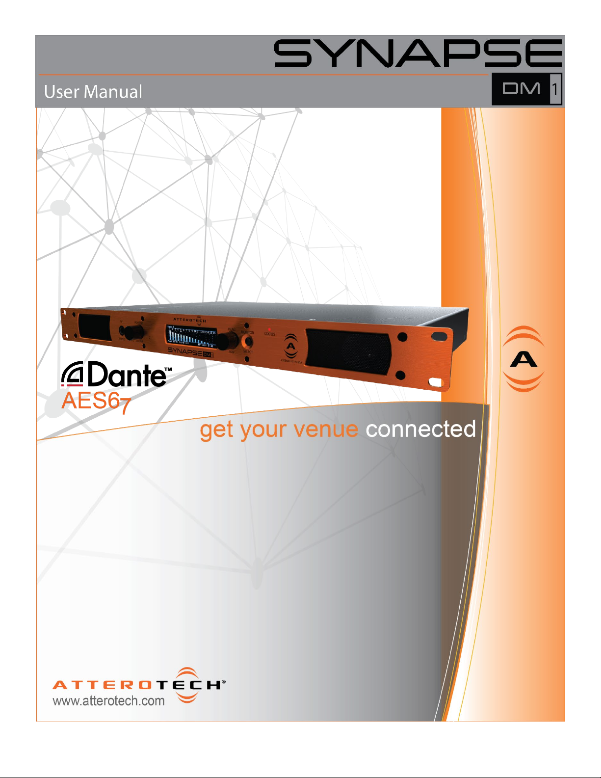
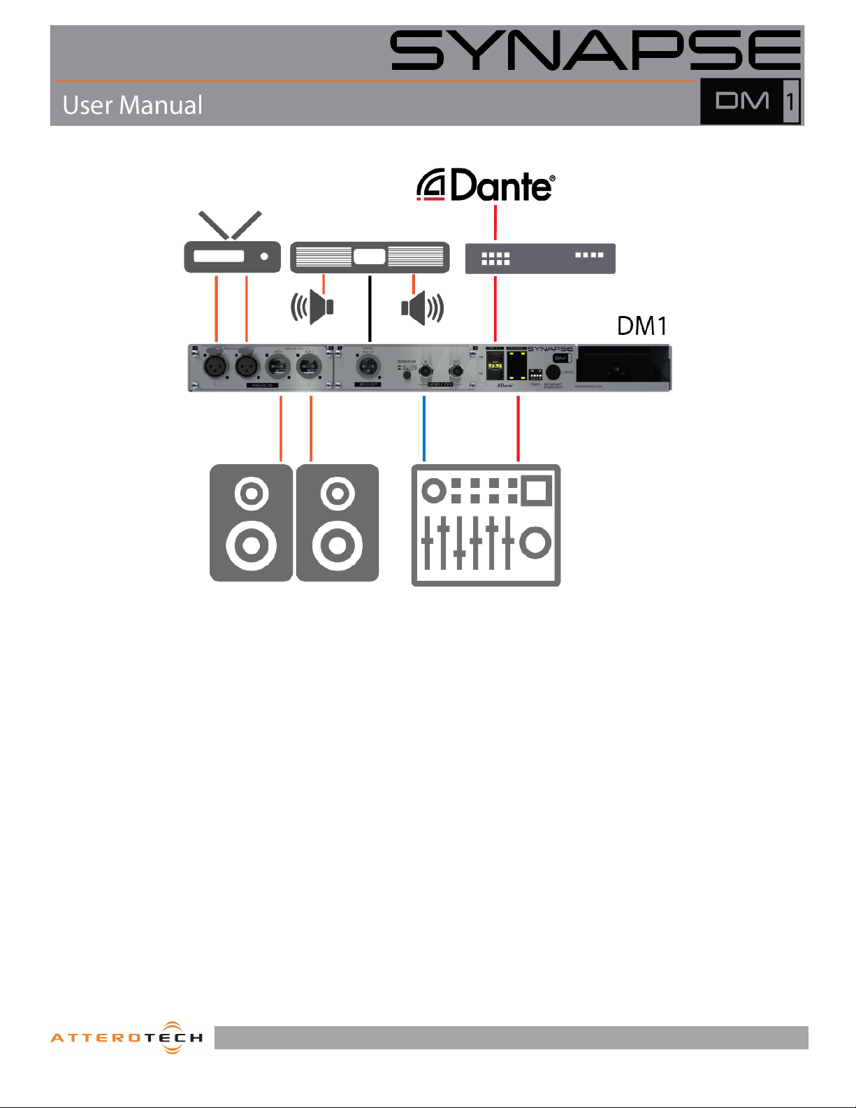
The Synapse DM1 is a rackmount networked audio monitor for
confidence monitoring of networked audio and local sources via
headphones or through the integrated speakers. The DM1 has 2
modes for network audio monitoring: Standard and Extended.
Standard mode features monitoring of any of the 32 channels
assigned to the Dante™/AES67 receiver inputs.
Extended mode allows subscription based monitoring of up to 128
channels loaded to the DM1 using the unIFY control Panel
software.
In both modes, audio may be selected for monitoring by the user
via the front panel controls. The DM1 also features AES-3 digital
outputs for connectivity to full range powered speakers or
amplifiers and 2 channels of analog I/O for local source monitoring
and network connectivity.
The front panel features an accessible integrated headphone amp
and a high contrast OLED display to provide quick and detailed
feedback for audio confidence monitoring and diagnostics.
The 24V power supply comes pre-mounted to the DM1 chassis but
there is also support for a secondary external 24V DC supply for
optional power redundancy.
On the network side, there is a fully redundant Dante™ interface
utilizing both RJ45 connectors and SFP ports. The SFP ports allow
the DM1to utilize direct fiber connectivity for long range signal
extension in physically large systems such as arenas, large
corporate buildings and convention centers.
Audinate’s Dante™ Controller or other 3rd party manufacturer's
Dante™ routing software can be used to control the Dante™ audio
routing configuration of the device while the Attero Tech unIFY
Control Panel application can be used to configure the devicespecific features.
1.1 – What’s in the Box
The Synapse DM1 comes supplied with the following:
o Synapse DM1 device
o AC Mains power cord
1.2 – Optional Extras
The following are available as options for the Synapse DM1 and
may be ordered separately:
o 24V DC Redundant Power Supply ( P/N: 256-00014-01)
o 1Gbit Fiber SFP Module ( P/N: 065-00038-01)
1315 Directors Row Suite 107 Fort Wayne, IN 46808 ⁞ (260) 496-9668 ⁞ www.atterotech.com
Page 5
Page 6
DEVICE FEATURES
FRONT PANEL
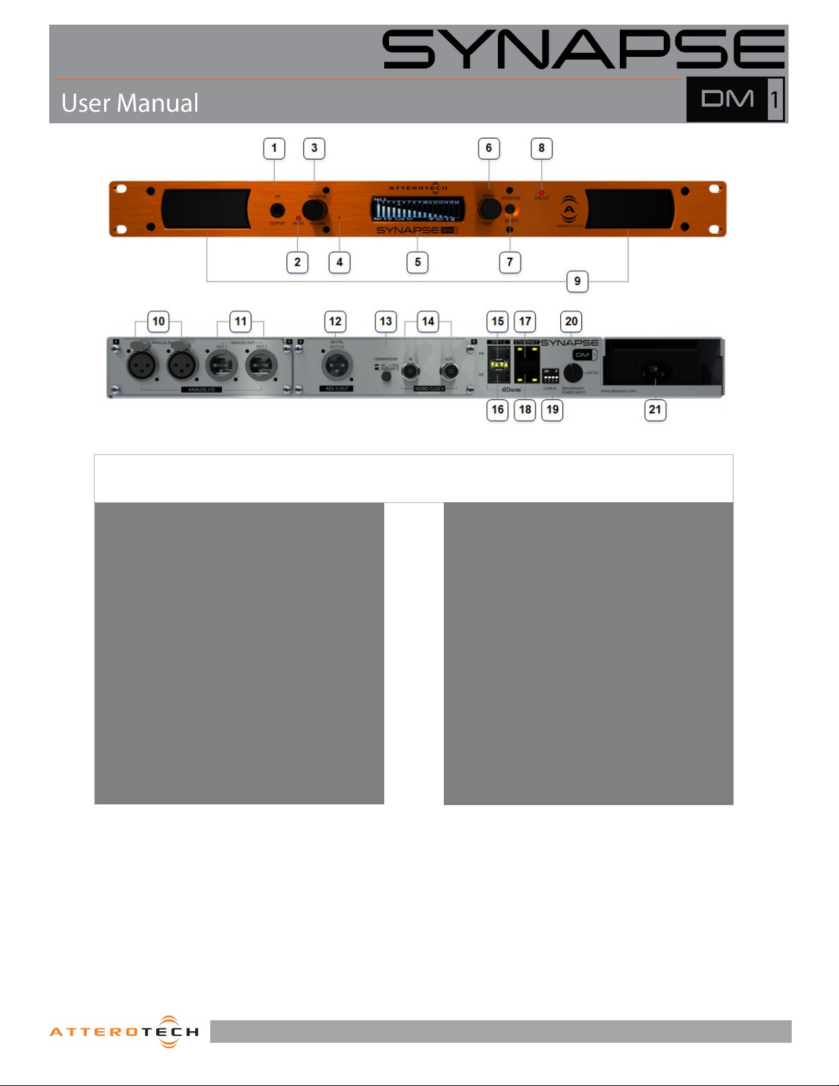
1 – Headphone Jack
*Note: The Synapse DM1 has a label on the base of the unit that shows the device’s MAC address. This is important for initial device
identification as the last six digits make up part of the device’s default network name that is shown when the device is detected by Dante™
Controller of unIFY Control Panel.
2 – Mute Indicator
3 – Volume/Mute Knob
4 – Factory Reset Switch
5 – OLED Display
6 – Front Panel Nav Knob
7 – Monitor Select Switch
8 – Device Power/Status LED
9 – Front Panel Speakers
10 – Analog XLR Inputs
11 – Analog XLR Outputs
12 – Digital AES-3 Output
13 – Word Clock 75Ω Input Termination Switch
14 – Word Clock In/Out
15 – SFP port (Primary)
16 – SFP (Secondary)
17 – Ethernet Port (Primary)
18 – Ethernet Port (Secondary)
19 – DIP Switches (Future Use)
20 – Redundant Power Input
21 – Primary Power Supply
REAR PANEL
1315 Directors Row Suite 107 Fort Wayne, IN 46808 ⁞ (260) 496-9668 ⁞ www.atterotech.com
Page 6
Page 7
2 – Device Installation
2.1 – Mounting
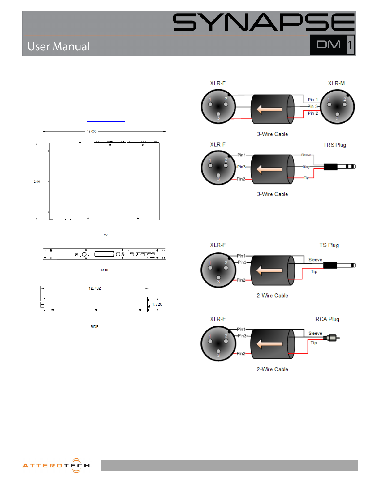
The case for the DM1 is designed ready to fit in a standard 19”
rack. The rack mount tabs are built in to the front panel of the
unit (rack screws are not supplied). Use four screws to secure
the unit to the rack. Dimensioned drawings can be obtained by
logging into Attero Tech’s customer portal
.
2.2.1 – Balanced Input from Balanced Output
Figure 1 – Mounting and Dimension Information
2.2 – Audio Connections
All connections to the Synapse DM1 should be made before the
power is applied. Attach analog audio sources to the analog
audio inputs. Attach analog audio destinations to the analog
audio outputs. Digital AES-3 destinations should be connected
to the AES-3 output. The analog audio outputs are balanced, so
be sure to check what input type the destination device uses in
order to find how to connect it correctly. Refer to the following
diagrams and instructions for connecting different types of
audio devices.
Figure 2 – Balanced Wiring Guide
2.2.2 – Balanced Input from Unbalanced Output
Figure 3 – Balanced Wiring Guide
1315 Directors Row Suite 107 Fort Wayne, IN 46808 ⁞ (260) 496-9668 ⁞ www.atterotech.com
Page 7
Page 8
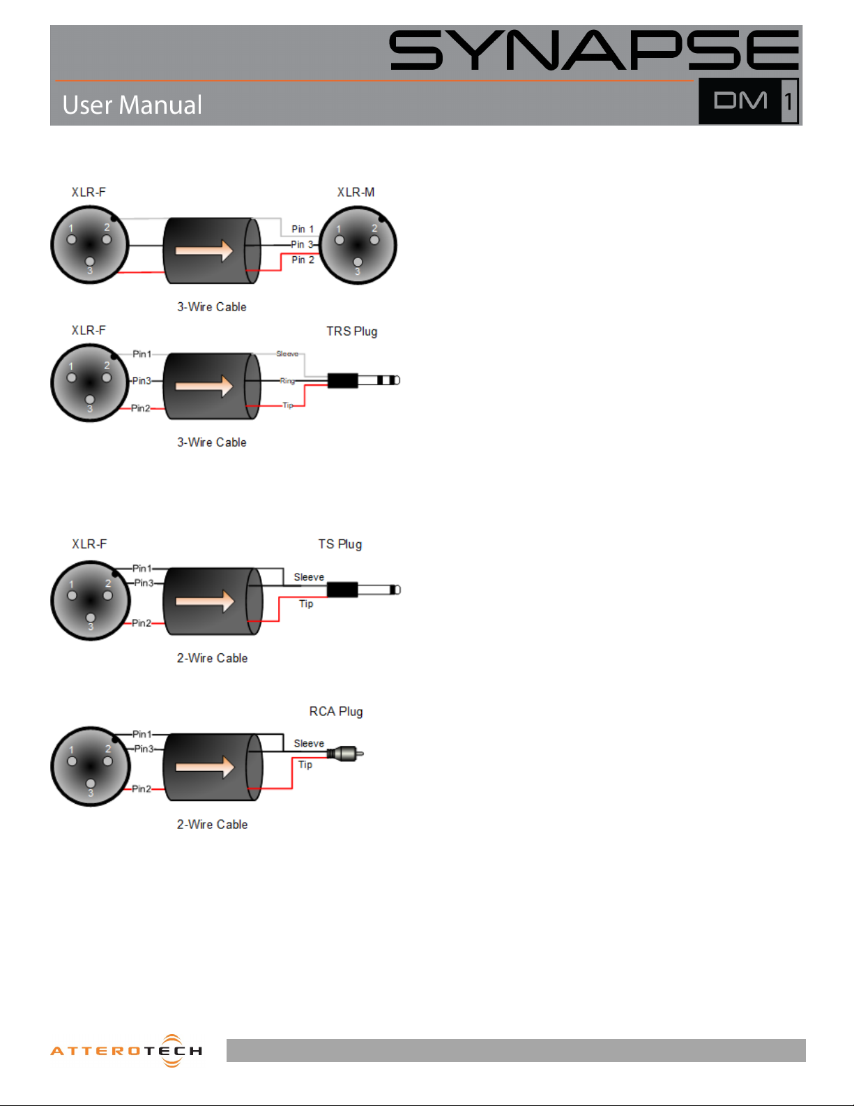
2.2.3 – Balanced Output to Balanced Input
Figure 4 – Balanced Wiring Guide
2.2.4 – Balanced Output to Unbalanced Input
2.3 – External Clocking
The DM1 is equipped with a single word clock input and output
for synchronizing digital devices. A user switchable 75 Ω clock
termination impedance is also located on the back panel.
2.4 – Power Supply
Use the provided AC power cable to connect a standard AC outlet
to the power supply input connector. There is no “on” switch so
the unit will power up as soon as the power connection is made.
*Note: If using the optional backup supply, avoid connecting a
powered supply to the unit. It is recommended to attach the power
supply to the D32o first, then connect the power cord to the power
supply to supply power to it.
Once powered, the screen on the front of the unit should turn on
and show the Attero Tech logo, the status LED should be red and
the mute LED should be flashing red rapidly. Initialization can up
to 20 seconds depending on how the device is setup. Once
initialized, the status LED will turn green, the mute LED will go
out, and the screen will change to show the first of the metering
screens.
There may also be some activity on the Dante™ RJ45 Ethernet
connector LEDs. If a cable is connected and no network is
detected, both LEDs will remain off. If an active connection is
made the green LED will come on and the yellow LED will flash.
Figure 5 – Unbalanced Wiring Guide
1315 Directors Row Suite 107 Fort Wayne, IN 46808 ⁞ (260) 496-9668 ⁞ www.atterotech.com
Page 8
Page 9
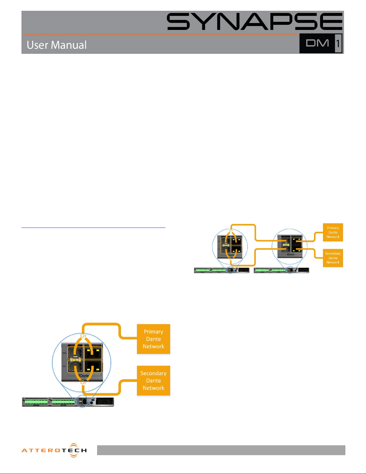
2.5 – Network Connections
*Note: All Attero Tech products are tested using UTP cabling and
it is recommended that UTP cabling be used when installing them.
STP cabling can be used for installation though care must be
taken not to introduce grounding issues into the system by doing
so.
Network connection is made using the RJ45 ports and SFP ports.
To use an SFP port, a suitable SFP module(s) will be required to
be installed. These are not included with the D32o and must be
purchased separately. In general, any 1Gbit SFP compatible
module may be used.
*Note: If there is no network connection, the front panel will show
“No Network” in the center of all the metering screens. The
network screen will also indicate that there are no active
interfaces.
Dante™ networks can be configured in two different ways:
standalone or redundant. The Synapse D32o can be used in either
configuration. By default the D32o is set to “Redundant” mode
but this can easily be changed using Dante™ Controller.
2.5.1 – AES67 Audio Network Note
For successful deployment of Attero Tech’s AES67 enabled
products, it is necessary to insure the AES67 audio network is
properly configured. A Quick Start Guide for AES67 Audio
Networking is available from the Attero Tech Customer Portal at
https://portal.atterotech.com/home/?v=files/560321a2b075c
As setup needs may vary by product, it may also be necessary to
check with the AES67-enabled product manufacturer as well.
2.5.2 – Using on a Redundant Network
The DM1 is setup for use in a redundant network out of the box.
In this mode the DM1 effectively has two separate network
connections, each with its own unique IP address. Both IP
addresses also need to be on completely different subnets.
By default, both ports of the DM1 in redundant mode will get their
own IP from a DHCP server if one is available. If not, the interfaces
will fall back to a local link address. For the primary port, that will
be in the range 169.254.x.x. For the secondary port, that will be
in the range 172.31.x.x. Static addresses may be assigned to one
or both interfaces using Dante™ Controller.
.
Connecting both the primary and secondary connections of any
Dante™ device to a network setup for redundancy *WILL* cause
network problems if the device not configured in “Redundant”
mode. As only the primary interface is required for initial setup,
if there is any doubt as to what configuration *ANY* device on the
network has, it is recommended only the primary ports of all
devices be connected to the primary network and all secondary
port connections are left disconnected. Once all devices that
support redundancy are confirmed as being configured in
“Redundant” mode, the secondary ports of all the Dante devices
can then be attached to the secondary network.
For the DM1, when connecting the primary Dante™ network,
either the primary SFP port or the primary RJ45 port can be used.
Similarly, when connecting the secondary Dante™ network, either
the secondary SFP port or the secondary RJ45 port can be used.
*Note: The connections to the primary and secondary Dante™
networks don’t have to use the same type of port on the DM1.
They may be mixed so using a primary SFP connection and an
RJ45 secondary connection or vice versa are both perfectly
acceptable.
Once connections to the main primary and secondary networks
have been made, the unused ports can be used to create a daisy
chain to a nearby device. Simply connect the spare primary port
to the primary port of the nearby device. To maintain full
redundancy, the spare secondary port should also be connected
to the secondary port of the nearby device.
Figure 7 - "Redundant" mode with daisy chaining
*Note: There are limitations using daisy chaining due to the
additional switch hops of a daisy chained switch/device in a
Dante™ network. While daisy chaining can certainly offer the
installer some benefits, careful consideration should be given as
to whether daisy chaining is suitable for any given application.
Figure 6 –"Redundant” mode, no daisy chain
1315 Directors Row Suite 107 Fort Wayne, IN 46808 ⁞ (260) 496-9668 ⁞ www.atterotech.com
Page 9
Page 10
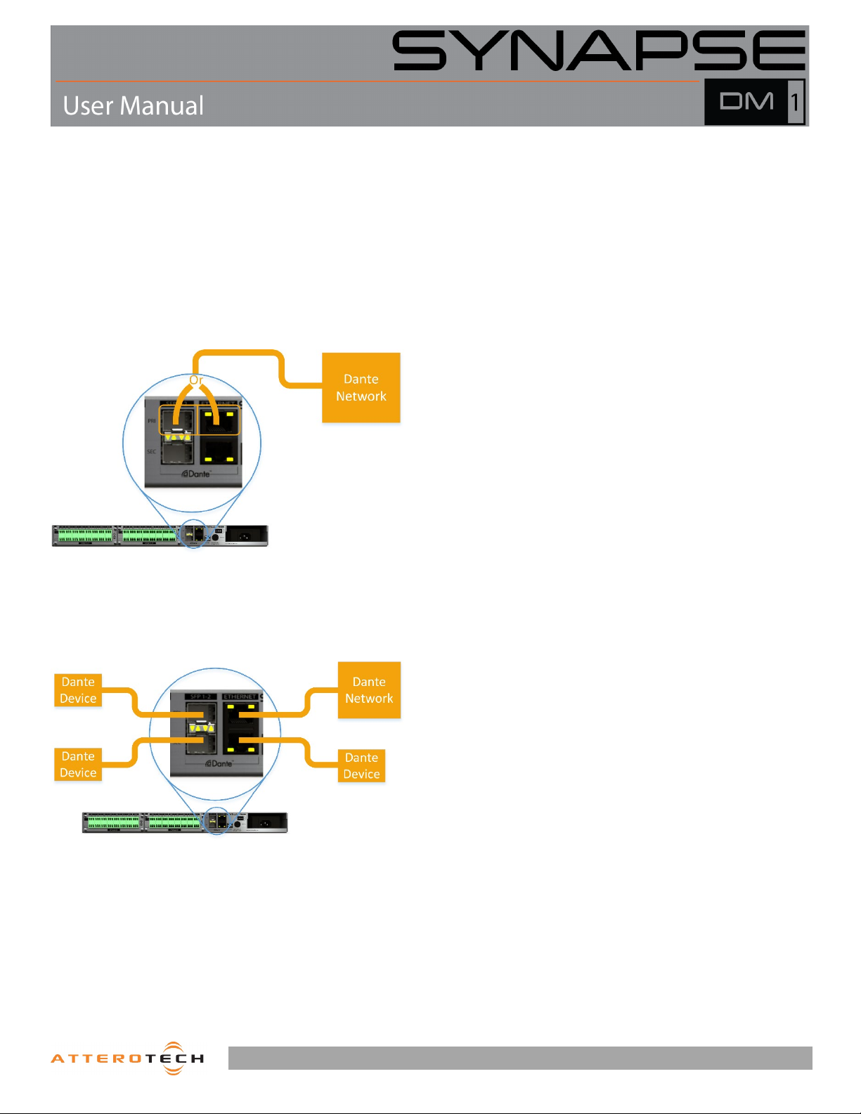
2.5.3 – Using on Standalone Network
The DM1 supports both redundant mode and standalone mode
(indicated as “switched” mode in Dante™ Controller). If the DM1
is being used in a standalone network, running the DM1 in either
“Redundant” or “Switched mode is perfectly acceptable and will
work so even though the DM1 is setup in “Redundant” mode by
default, it can and will work happily in a standalone network
without changing anything. However, only the primary SFP port
or primary Ethernet port of the DM1 may then be connected to a
standalone Dante™ network.
*Note: Connecting either secondary port to a standalone Dante™
network while the DM1 is still set in “Redundant” mode will cause
problems due to the IP address setup of the secondary ports
having completely different IP addresses. Therefore this should
be avoided.
Figure 8 - "Standalone" connection in “Redundant” mode
For full flexibility in a standalone network, the DM1 should be
reconfigured to “Switched” mode. This is easily done by
connecting one of the primary ports to the standalone Dante™
network and then using Dante™ controller to switch the mode.
Figure 9 - "Standalone" connection in "Switched" mode
In “Switched” mode, the DM1 reverts to using a single internal
network connection with a single IP address. The concept of
primary and secondary ports become irrelevant and all of the
ports (both SFP and RJ45) are connected together on the same
network essentially turning the DM1 into a regular four port
network switch.
In this mode, the Dante™ network can be connected to any of the
four ports. Any unused ports may then be used to connect other
devices in a daisy chain. As the DM1 is acting as a switch, other
devices connected to the DM1 must then count the DM1 as a
switch hop.
1315 Directors Row Suite 107 Fort Wayne, IN 46808 ⁞ (260) 496-9668 ⁞ www.atterotech.com
Page 10
Page 11
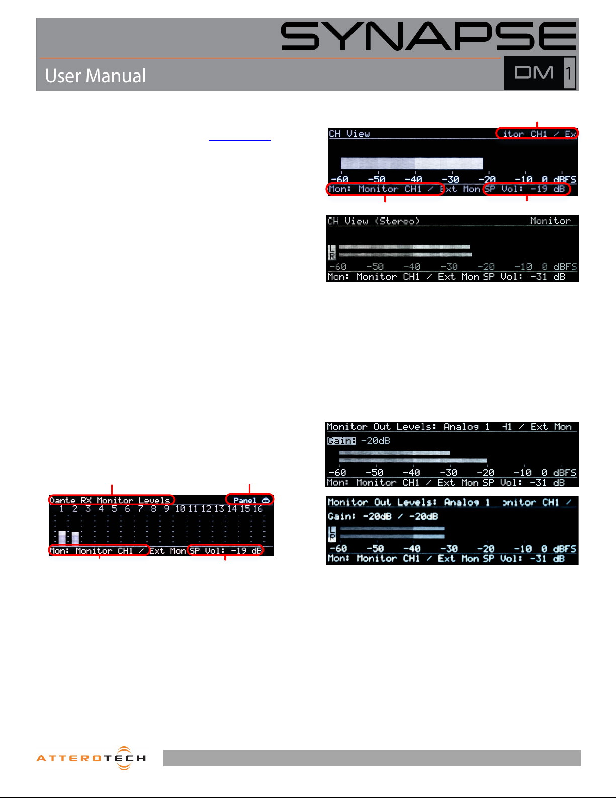
3 – Device Operation
Panel Lock
Speaker/HP Vo lumeMonitor Channel
Screen name
Chan nel Name (Dante Tx Name)
Monitor Channel
Speaker/HP Vo lume
Certain features of the DM1 such as channel mutes, output
level, and front panel lockout are controlled using unIFY Control
Panel application. This is available from the customer portal
section of our website. Details of those features are shown in
the help documentation for unIFY Control Panel.
Some features of the device are operated from the various
controls on the front panel such as the main display.
3.1 – Display View Operation
During power up the display will show the Attero Tech logo. Once
the device is running, the display will switch to showing a normal
view. If there are any problems, the display will indicate a POST
(Power-On Self-Test) error. If this happens contact Attero Tech
technical support.
Once up and running, the front panel can show various different
views and is used to control a number of DM1 features. To save
power, the display will turn itself off after 30 seconds of inactivity.
To activate the display again, press either of the knobs to activate
their buttons or the monitor select button. The Display Timeout
timer can be adjusted in unIFY Control Panel.
*Note: Turning a knob will NOT turn the screen back on. It must
be a button push.
Navigating the views on the display is achieved using the “Menu
Nav” knob. Rotating this left or right will step through the various
views available. If the front panel lock has been activated by
unIFY, the panel lock icon will be shown in the upper right hand
corner of the display and while the “Menu Nav” knob can still be
used to rotate the different views no further action can be taken
on any view.
3.1.1 – Dante™ RX Monitor Levels
Each individual Dante™ channel and analog input has its own
view. The meter itself is shown in the horizontally across the main
part of the view from left to right. The name of the current
channels meter being shown is displayed in the upper left hand
corner. The name in parenthesis that follows the name is the
channel name that this channels is identified by on the Dante™
network. This view can also be used to select the monitor output
if the front panel lock is not active. To do so, with the desired
channel on view, click the “Monitor Select” button.
In Stereo Mode, the meters will be paired in L/R channels.
3.1.3 – Monitor Out Level View
There are two views for bank metering. The main part of each
bank view shows meters for each Dante™ input in that bank. This
view can be used to select the monitor output if the panel lock is
not active by pressing in the “Menu Nav” button. This activates a
cursor that can be scrolled used the knob to select one of the
visible channels. Once the desired channel is selected, press the
separate “Monitor Select” button and that channel will when be
routed to the speakers/headphone outputs.
3.1.2 – Channel Metering Views
1315 Directors Row Suite 107 Fort Wayne, IN 46808 ⁞ (260) 496-9668 ⁞ www.atterotech.com
The Monitor Out Level View shows the level and gain settings for
Analog Outputs 1 and 2. The name of the current channels meter
being shown is displayed in the upper left hand corner.
Pressing the Menu/Nav knob will allow adjustment of the
respective output gain level. The meter will display in a split view,
the top being the output gain level being adjusted while the lower
is the current monitor speaker level.
In Stereo Mode, the meters will be paired in L/R channels
representing the output levels. Both meters will adjust with the
gain parameter.
Page 11
Page 12
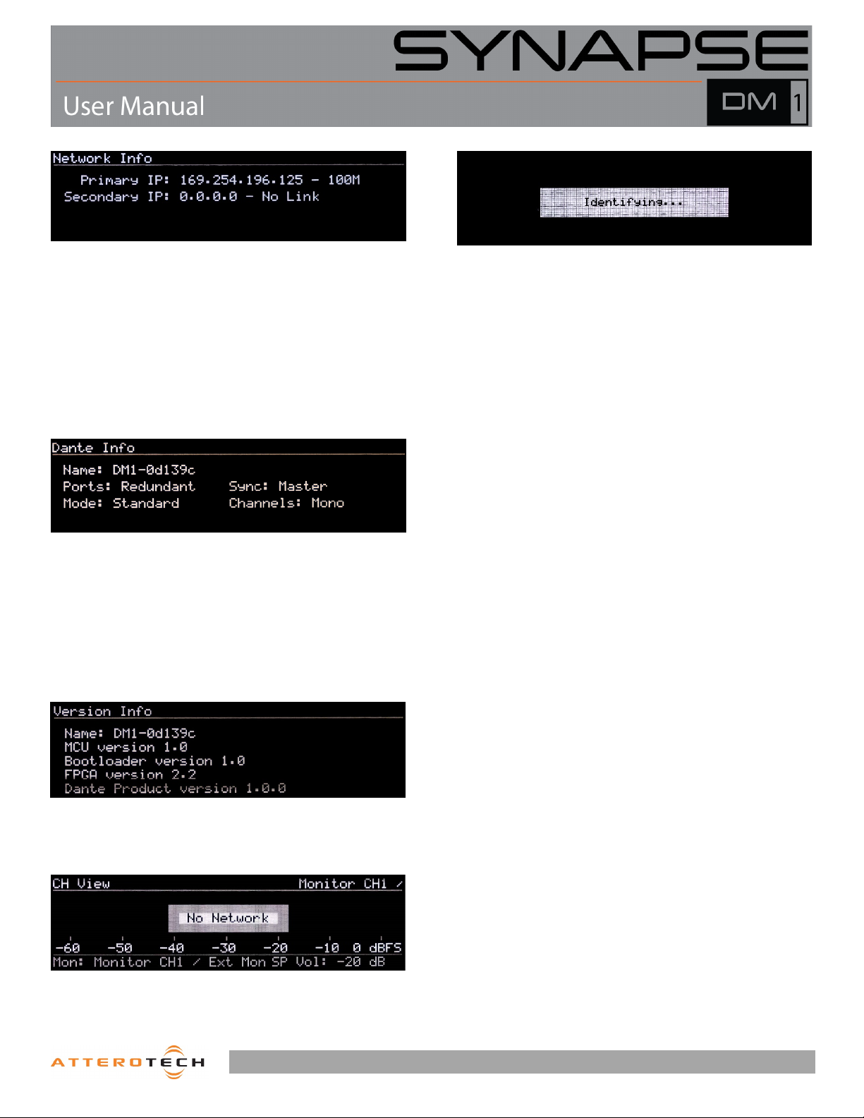
3.1.4 – Network Info View
3.1.8 – Identify
The Network info view shows the IP addresses and link speed of
the DM1’s interfaces. In redundant mode, both a primary and a
secondary interface will be shown. The primary port speed will
always indicate the faster of the two possible primary links if they
are both used. The same is true the secondary port speed if both
secondary links are used.
In switched mode, only one interface with its IP address is shown
and the speed indicated will be the fastest speed of any of the
four possible links.
3.1.5 – Dante™ Info View
The Dante™ info view shows information about the Dante™ setup.
The device Dante™ name, its port mode and the devices clock
sync status are all shown. The Dante™ name is name the device
identifies itself as on the Dante™ network. The port state shows
if the device is in either redundant mode or switched mode. The
clock sync indicates whether the device is the “Master” clock for
the system or if it’s a “Slave” to another device. A state of “No
Sync” may indicate a possible problem with either the device or
the network.
3.1.6 – Version View
The “Identify Device” option allow devices on the network to be
visually located. This feature will flash the Status/Power LED, and
display the above message on the front panel display of the
selected device in unIFY Control Panel. See the unIFY Control
Panel manual for more information on using this function.
*NOTE: On Synapse devices, the front panel controls will not
operate until the Identify function is disabled.
The Version view gives version information about the various
parts of the device.
3.1.7 – No Network
If the DM1 becomes disconnected from the Dante network at
any time, that will be indicated on various views. The metering
views will show a “No Network” message while the Network view
will show “No Network” for all indicated interfaces.
1315 Directors Row Suite 107 Fort Wayne, IN 46808 ⁞ (260) 496-9668 ⁞ www.atterotech.com
Page 12
Page 13
3.2 – Audio Monitoring
The DM1 is equipped with two onboard options for monitoring
incoming signals:
o Integrated front panel speakers
o Headphone output
There are two modes for Dante™ monitoring:
o Standard Mode
o Extended Mode
All monitoring modes support mono or stereo capability. In mono
mode, a single selected channel is routed to all outputs. In stereo,
the left/right audio outputs receive independent audio
assignments.
3.2.1 – Speaker Monitoring
The DM1 is equipped with speakers integrated in the front panel
to monitor audio signals in the device. The currently selected
channel for monitoring is shown in the bottom left corner of any
of the metering views. Selecting a channel can be done from any
of the metering views. The speaker output has both volume and
mute controls available.
3.2.2 – Jack Detect Mode
The DM1 internal speakers support a user configurable jack
detect mode. If enabled, the speakers will automatically be
muted if a headphone plug is connected. If disabled, the
speaker output will remain active regardless of connected
headphones.
3.2.3 – Headphone Monitoring
The DM1 has a headphone output that can be used to discretely
monitor audio signals in the device. The currently selected
channel for monitoring is shown in the bottom left corner of any
of the metering views. Selecting a channel can be done from any
of the metering views. The headphone output has both volume
and mute controls available.
3.2.4 – Volume Control
The current volume level is indicated in the lower right corner of
the display on any of the metering views. The volume is controlled
with the monitor volume knob just to the right of the headphone
output jack itself. Turning the knob clockwise increases volume
while turning it counter-clockwise decreases the volume level.
3.2.5 – Mute
The volume knob also acts as a mute control. The state of the
mute is indicated by the mute LED just to the left of the volume
knob. The LED will be red while the mute is active and off
otherwise. To toggle the mute state, push the volume knob to
activate its button.
3.2.6 – Monitor Input Select
The active monitor source is selectable from the front panel for
either incoming Dante™ channels, or the local analog line inputs.
3.2.7 – Dante™ Monitoring
Two modes of Dante™ monitoring are available based on
application needs
3.2.7.1 – Standard Mode
In standard mode, the DM1 allows user selection from any of up
to 32 Dante™ audio channels. In this mode, audio is directly
assigned using Dante™ Controller to each of the 32 DM1 Dante™
RX channels. In stereo mode, audio is routed in channel pairs to
the audio outputs.
Channels are navigated and selected from the front panel controls
once they have been assigned.
3.2.7.2 – Extended Mode
In extended mode, it is required to first pre-configure a list of
monitoring channels using unIFY Control Panel. The channel list
can contain up to 128 total mono audio channels, or 64 pairs in
stereo mode. It is not necessary to enable all channels. Friendly
names can be used to identify monitoring channels.
Channels are navigated and selected from the front panel controls
once they have been assigned. Only enabled and assigned
channels are available on the front panel for monitor selection.
1315 Directors Row Suite 107 Fort Wayne, IN 46808 ⁞ (260) 496-9668 ⁞ www.atterotech.com
Page 13
Page 14
3.3 – Factory Reset
Should it be necessary, the DM1 has a factory reset option.
Activating it affects both Dante™ and non-Dante™ settings of the
device. All Dante™ settings are reset including device name and
channel names, the Ethernet port mode will be defaulted back to
redundant mode and the IP address setup will be reset to get an
IP address dynamically.
The factory reset switch is accessed through a small hole on the
front panel. The active the factory reset insert a paperclip or small
screw driver into the factory reset hole and press and hold the
factory switch for five seconds. Once the switch has been in for
long enough, if the screen was active, the screen will blank,
releasing the switch after 5 seconds will then start the factory
reset process.
3.4 – Firmware Updates
If a firmware update for the DM1 is released, it may be applied in
the field by the end user or installer. The update process takes
advantage of the smart firmware update tool in unIFY. The unIFY
Control Panel application is available from the customer portal
the Attero Tech website.
To apply the update, download the appropriate SFU file for the
DM1, select the smart firmware update option under the Tools
menu and follow the instructions. Further assistance for doing
updates is provided in the unIFY Control Panel manual.
on
3.5 – Third Party Control
The DM1 offers some support for real time third party control.
The commands the DM1 support and the protocol it uses are all
outlined in the unIFY 3
from the customer portal
rd
party software API document available
on the Attero Tech website.
1315 Directors Row Suite 107 Fort Wayne, IN 46808 ⁞ (260) 496-9668 ⁞ www.atterotech.com
Page 14
Page 15
ARCHITECTS & ENGINEERS SPECIFICATION
The Dante™ interface shall have 32 Dante™ receive channels that may be selected by the user from the front panel for monitoring through
the integrated speakers, headphone, AES-3 and analog outputs.
The interface shall provide visual indication of audio levels from the front panel display, in both 16 channel bank summary and individual
channel views.
The interface shall support master and slave synchronization of external word clock devices via the rear panel BNC connectors.
The interface shall support extended monitoring capabilities of up to 128 channels using remote Dante™ subscription from the device.
The rear panel analog inputs shall support local monitoring as well as transmission to the Dante™/AES67 network.
The rear panel analog inputs and outputs shall be available on 3 pin XLR connectors.
The Dante™ interface shall support a switched or redundant network mode.
The device shall have two integrated Gigabit Ethernet ports on RJ-45 connectors and 2 gigabit SFP expansion slots for connectivity to a
Dante network.
All parameter changes will be non-volatile and self-restoring in the event of power interruption.
The device shall support power redundancy.
The device shall be compliant with FCC 47CFR parts 15B and 18 (Class A), EN 55011, ICES-003, RoHS and CE (EN55022 Class A and EN55024
Class A).
The device shall be the Attero Tech Synapse DM1.
1315 Directors Row Suite 107 Fort Wayne, IN 46808 ⁞ (260) 496-9668 ⁞ www.atterotech.com
Page 15
Page 16
Device Specifications
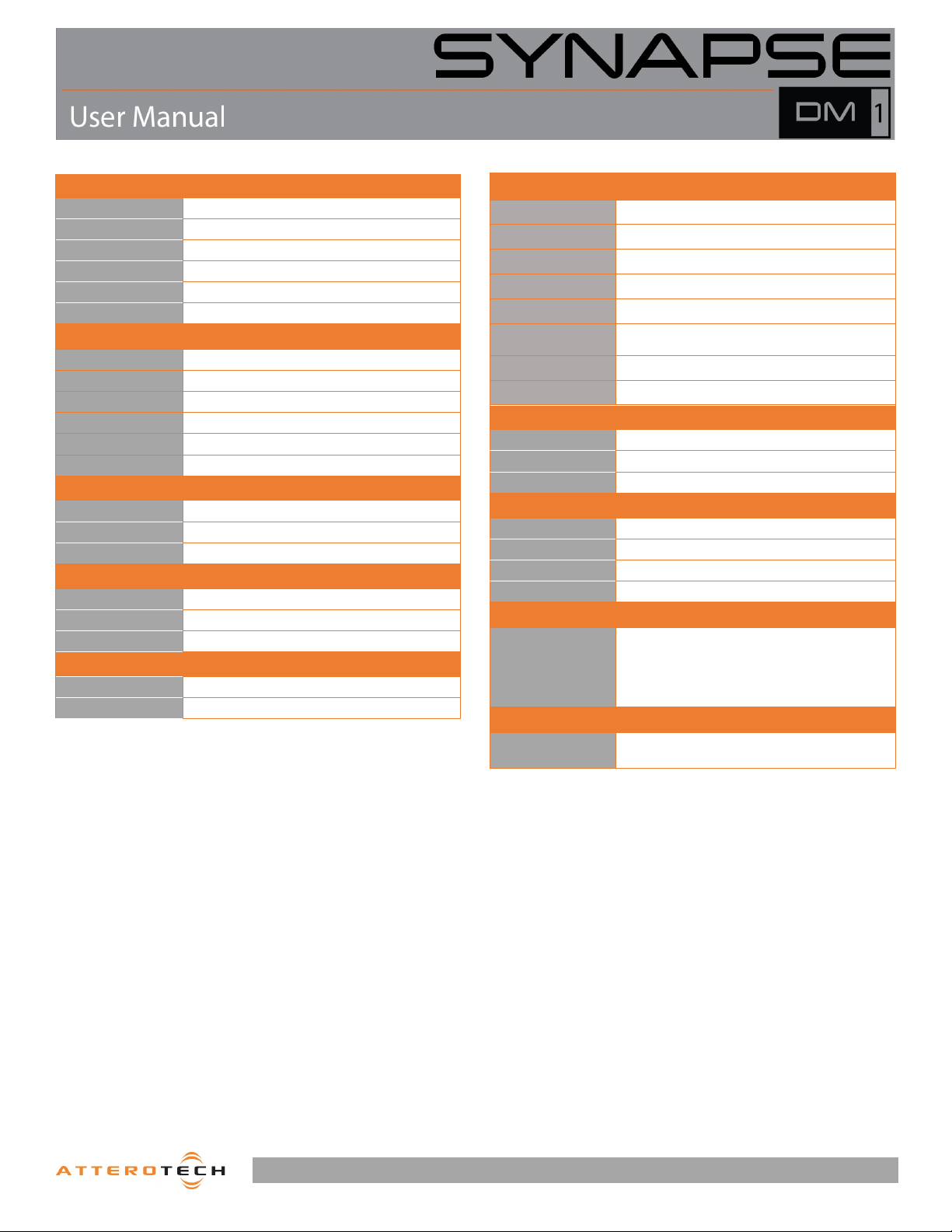
REACH
Analog Audio Inputs
Input Type 2 – 3-pin Balanced XLR-F
Input Impedance
Maximum Input Levels +24 dBu (+/- 0.5 dB)
THD+N ≤ 0.005% at -3 dBFS
Dynamic Range > 105 dB
Frequency Response 20-20kHz, +/- 0.5dB
Output Type 2 – 3-pin Balanced XLR-M
IOutput Impedance
Maximum Output Levels +24 dBu (+/- 0.5 dB)
THD+N ≤ 0.005% at -3 dBFS
Dynamic Range > 105 dB
Frequency Response 20-20kHz, +/- 0.5dB
Output Type Stereo headphone on ¼” TRS
Maximum output level
THD+N < 0.01 % @ 25mW
Output Power 3 W/channel
Output Impedance
Frequency Response 250 Hz – 20 kHz +/-3 dB
AES-3 AES-3 digital output on 3-pin XLR-M
Word Clock
10 Ω
Analog Audio Outputs
200 Ω
Headphone Output
25mW into 32 Ω
Speaker Outputs
8 Ω
Digital I/O
Sync I/O on BNC with switchable 75 Ω termination on input
Dante Network
Physical Layer Ethernet
Connector (s) Dual RJ-45 / Dual SFP Slots
Cable Quality CAT-5e or better (Copper) / Fiber
Transmission Speed All interfaces 1 Gbps
Supported Sample Rates 44.1kHz /48kHz / 88.2 kHz / 96 kHz
Minimum Dante
Network Latency
Supported Modes Redundant / Switched
AES67 Support Dante™ – AES67 Mode
AC Po wer 120V AC
Power Consumption < 20W Max
Cable Quality CAT-5e or better
Width 19"
Height 1.75” (1 RU Form Factor)
Depth 12.5"
Weight 6 lbs
Certifications
Environmental Operating Specifcatons
Operating Temperature
250 us
Power Specifications
Physical Dimensions
Regulatory Compliance
FCC CFR 47 Parts 15B Class A, EN55011
ICES-003
CE (EN55022 / EN55024)
RoHS
0 to 40° C
Page 16
1315 Directors Row Suite 107 Fort Wayne, IN 46808 ⁞ (260) 496-9668 ⁞ www.atterotech.com
 Loading...