

Page 1
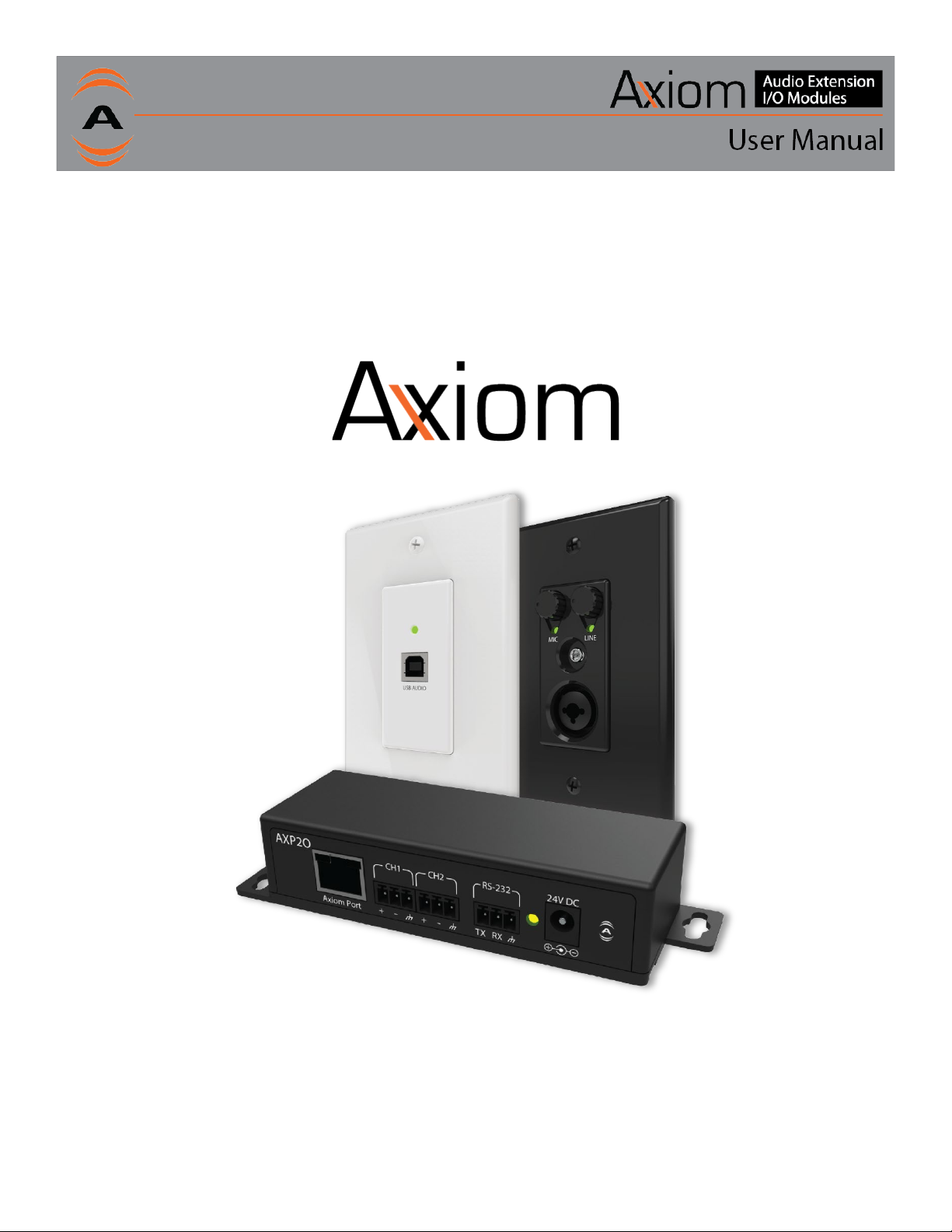
Audio Extension I/O Modules
614-00063 Rev 01 Attero Tech LLC 2019
8/2019
Page 2
IMPORTANT SAFETY INSTRUCTIONS
The symbols below are internationally accepted symbols that warn of potential hazards with electrical products.
This symbol, wherever it appears, alerts you to the presence of un-insulated dangerous voltage inside the enclosure -- voltage
that may be sufficient to constitute a risk of shock.
This symbol, wherever it appears, alerts you to important operating and maintenance instructions in the accompanying literature.
Please read the manual.
1. Read these instructions.
2. Keep these instructions.
3. Heed all warnings.
4. Follow all instructions.
5. Do not use this apparatus near water.
6. Clean only with a dry cloth.
7. Do not block any ventilation openings. Install in accordance with the manufacturer's instructions.
8. Do not install near any heat sources such as radiators, heat registers, stoves, or other apparatus (including amplifiers) that produce
heat.
9. Do not defeat the safety purpose of the polarized or grounding-type plug. A polarized plug has two blades with one wider than the
other. A grounding type plug has two blades and third grounding prong. The wider blade or the third prong is provided for your
safety. If the provided plug does not fit into your outlet, consult an electrician for replacement of the obsolete outlet.
10. Protect the power cord from being walked on or pinched particularly at plugs, convenience receptacles, and the point where they
exit from the apparatus.
11. Only use attachments/accessories specified by Attero Tech
12. Use only with the cart, stand, tripod, bracket, or table specified by the manufacturer, or sold with the apparatus.
13. Unplug this apparatus during lightning storms or when unused for long periods of time.
14. Refer all servicing to qualified service personnel. Servicing is required when the apparatus has been damaged in any way, such as
power-supply cord or plug is damaged, liquid has been spilled or objects have fallen into the apparatus, the apparatus has been
exposed to rain or moisture, does not operate normally, or has been dropped.
15. When permanently connected, on all-pole mains switch with a contact separation of at least 3mm in each pole shall be incorporated
in the electrical installation of the building.
16. If rack mounting, provide adequate ventilation. Equipment may be located above or below this apparatus but some equipment (like
large power amplifiers) may cause an unacceptable amount of hum or may generate too much heat and degrade the performance
of this apparatus.
614-00063 Rev 01 Attero Tech LLC 2019
TO REDUCE THE RISK OF FIRE OR ELECTRIC SHOCK, DO NOT EXPOSE THIS APPARATUS TO RAIN OR MOISTURE.
8/2019
Page 3
equipment has been tested and found to comply with the limits for a Class A
These limits are
designed to provide reasonable protection against harmful interference when the
This equipment generates, uses,
and can radiate radio frequency energy and, if not installed and used in accordance with
.
equipment in a residential area is likely to cause harmful interference,
LIMITED FIVE YEAR WARRANTY
The equipment is warranted for five years from date of purchase from Attero Tech, LLC against defects in materials or workmanship. This
warranty does not cover equipment which has been abused or damaged by careless handling or shipping. This warranty does not apply to
used or demonstrator equipment. Should any defect develop, Attero Tech, LLC will, at our option, repair or replace any defective parts
without charge for either parts or labor. If Attero Tech, LLC cannot correct the defect in the equipment, it will be replaced at no charge with
a similar new item. Attero Tech, LLC will pay for the cost of returning your equipment to you. This warranty applies only to items returned
to Attero Tech, LLC, shipping costs prepaid, within five years from the date of purchase. This Limited Warranty is governed by the laws of
the State of Indiana. It states the entire liability of Attero Tech, LLC and the entire remedy of the purchaser for any breach of warranty as
outlined above. NEITHER ATTERO TECH, LLC NOR ANYONE INVOLVED IN THE PRODUCTION OR DELIVERY OF THE EQUIPMENT SHALL BE LIABLE
FOR ANY INDIRECT, SPECIAL, PUNITIVE, CONSEQUENTIAL, OR INCIDENTAL DAMAGES ARISING OUT OF THE USE OR INABILITY TO USE THIS
EQUIPMENT EVEN IF ATTERO TECH, LLC HAS BEEN ADVISED OF THE POSSIBILITY OF SUCH DAMAGES. IN NO EVENT SHALL THE LIABILITY OF
ATTERO TECH, LLC EXCEED THE PURCHASE PRICE OF ANY DEFECTIVE EQUIPMENT.
This warranty gives you specific legal rights. You may have additional legal rights which vary from state to state.
Note: This
digital device, pursuant to Part 15 of the FCC Rules and EN55022.
equipment is operated in a commercial environment.
the instruction manual, may cause harmful interference to radio communications
Operation of this
in which case the user will be required to correct the interference at their own expense.
1315 Directors Row Suite 107 Fort Wayne, IN 46808 ⁞ (260)496-9668 ⁞ www.atterotech.com
Page 4

Contents
1 – Axiom Bus Overview ............................................................................................................................................................................................................... 1
2 – ML1 – Overview .......................................................................................................................................................................................................................... 1
2.1 – ML1 – What’s in the Box .......................................................................................................................................................... 1
3 – Device Installation .................................................................................................................................................................................................................. 2
3.1 ML1 – Mounting ......................................................................................................................................................................... 2
3.2 – Signal Metering LED Indications .............................................................................................................................................. 3
3.3 – Controls ................................................................................................................................................................................... 3
3.4 - Device Configuration and Workflow Overview ........................................................................................................................ 3
4 – AXP2O – Overview .................................................................................................................................................................................................................... 4
4.1 – AXP2O – What’s in the Box ...................................................................................................................................................... 4
4.2 – USB1 – Device Installation ....................................................................................................................................................... 4
4.3 – Mounting ................................................................................................................................................................................. 5
4.4 – Audio Connections .................................................................................................................................................................. 6
4.5 – 3rd Party Control ...................................................................................................................................................................... 6
4.6 – RS-232 Interface ...................................................................................................................................................................... 6
ARCHITECTS & ENGINEERS SPECIFICATION ......................................................................................................................................................................... i
ML1 ................................................................................................................................................................ ..................................... i
AXP2O ................................................................................................................................................................ ................................. i
Device Specifications...................................................................................................................................................................................................................... ii
ML1 Specs .......................................................................................................................................................................................... ii
AXP2O Specs ..................................................................................................................................................................................... ii
1315 Directors Row Suite 107 Fort Wayne, IN 46808 ⁞ (260)496-9668 ⁞ www.atterotech.com
Page 5
1 – Axiom Bus Overview
8P8C
TIA 568A
TIA 568B
Axiom Port
1
3: Green/White
2: Orange/White
Analog Audio 1+
2
3: Green
2: Orange
Analog Audio 1-
3
2: Orange/White
3: Green/White
Analog Audio 2+
4
1: Blue
1: Blue
RS-232 TXD)
5
1: Blue/White
1: Blue/White
RS-232 RXD
6
2: Orange
3: Green
Analog Audio 2-
7
4: Brown/White
4: Brown/White
+24 VDC
8
4: Brown
4: Brown
GND
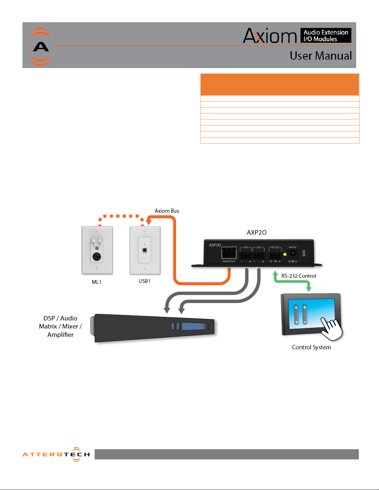
The Attero Tech Axiom bus is a proprietary analog extension
solution that leverages unshielded twisted pair cabling (CAT 5/6)
to transmit 2 balanced audio channels, RS-232 control and 24VDC
power for audio signal extension applications.
The Axiom bus is designed to support distances of up to 100m
(total run length). The Axiom bus also supports daisy chain
connectivity of up to 2 Axiom devices to provide flexible
modularity for various audio device connectivity in installed AV
systems.
Application Diagram
Pin
Pair: Color
Table 1 - Axiom Bus Details
Pair: Color
Function
Page 1
1315 Directors Row Suite 107 Fort Wayne, IN 46808 ⁞ (260)496-9668 ⁞ www.atterotech.com
Page 6
2– ML1 – Overview
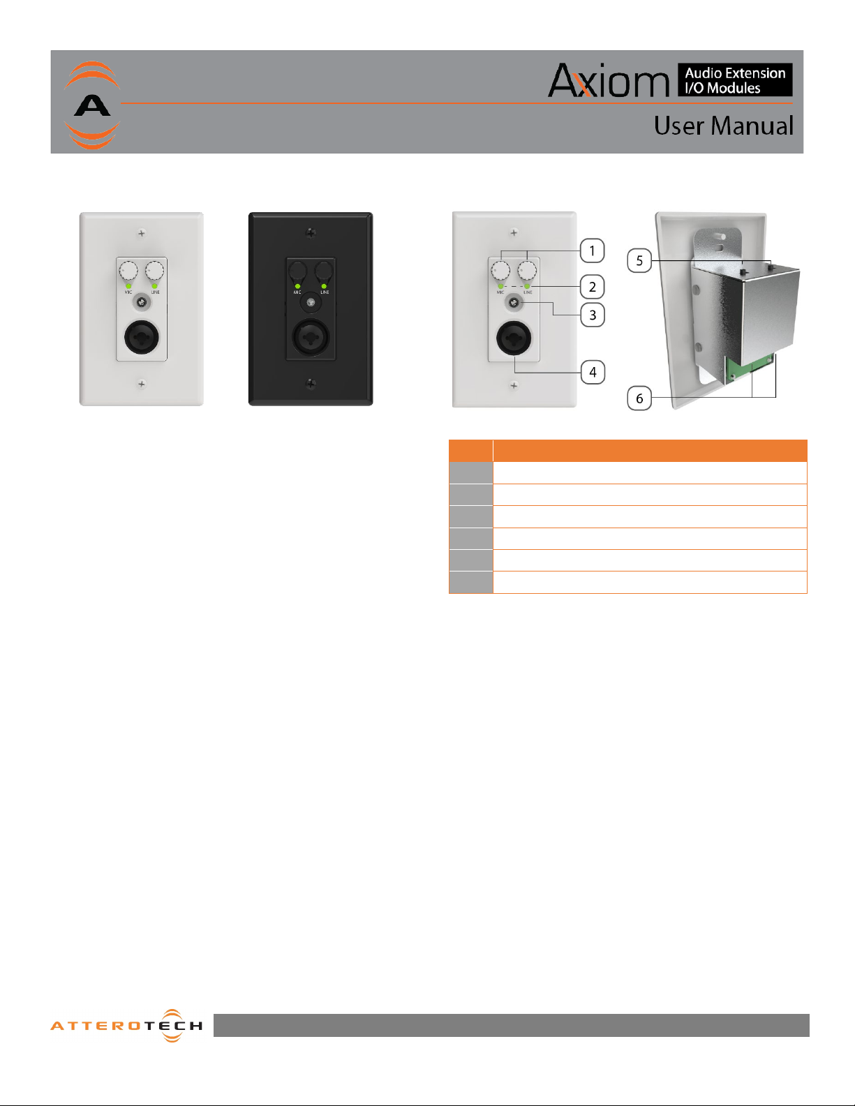
Figure 2 - Product Overview
Figure 1 – ML1 Front Panel
The Axiom ML1 provides an installation friendly simple to operate
analog audio extension solution for analog mic and line level
sources in cost-sensitive applications such as small and medium
sized retail, restaurant, education, and hospitality venues.
2.1 – ML1 – What’s in the Box
The ML1 comes supplied with the following:
o Axiom ML1device
o Includes interchangeable white and black Decora-style
o (1) White US Single Gang Decora® cover plate w/screws
o (1) Black US Single Gang Decora® cover plate w/screws
o (2) Wall plate mounting screws
inserts
Figure 3 - Product Overview
ID Description
1 Gain Adjust Knobs
2 Signal Presence Indicators
3 3.5mm Input
4 XLR/TRS Input (1/4” TRS Padded for +20dBu support)
5 Axiom Port A Configuration Switches
6 Axiom Ports (A & B)
1315 Directors Row Suite 107 Fort Wayne, IN 46808 ⁞ (260)496-9668 ⁞ www.atterotech.com
Page 1
Page 7
3 – Device Installation
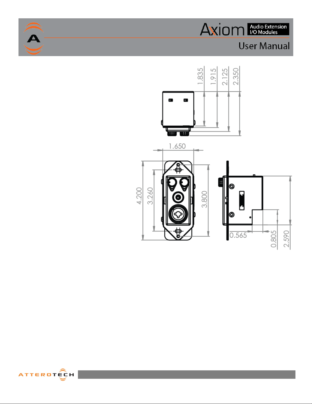
Figure 4 - Dimensional Drawing
3.1 ML1 – Mounting
A typical installation will involve mounting the wall plate
into a pre mounted wall box or mounting bracket. Before
installation, make sure the wall box where the ML1 is to
be installed is pre-wired with a suitable cable back to an
Axiom-enabled expander/injector.
Prior to ML1 installation, ensure the power sourcing
device (Axiom expander/injector) is powered off.
Attach and unshielded CAT-5/6 cable from the Axiomenabled device to the Axiom port A of the ML1.
With the cable attached, carefully place the ML1 into the
wall box taking care to not trap the cabling. Once in
place, secure it with the screws provided. Once the unit
is secured in the wall box, fit the Decora plate and secure
it with the screws provided.
Now you may apply power to the Axiom-enabled
expander/injector, the unit will power up and the signal
presence LEDs should blink once quickly.
The ML1 comes in a single gang US Decora style form
factor and may be mounted in most US single old and
new work back boxes and mud-rings. Given the single
gang size, the ML1 may be mounted in larger gang
boxes with other single gang form factor products to
provide flexible AV system modularity where needed.
*Note: CAD drawings can be downloaded from the
Attero Tech website. Please contact Attero Tech for any
further product related information that is not
accessible on the website.
1315 Directors Row Suite 107 Fort Wayne, IN 46808 ⁞ (260)496-9668 ⁞ www.atterotech.com
Page 2
Page 8
3.2 – Signal Metering LED Indications
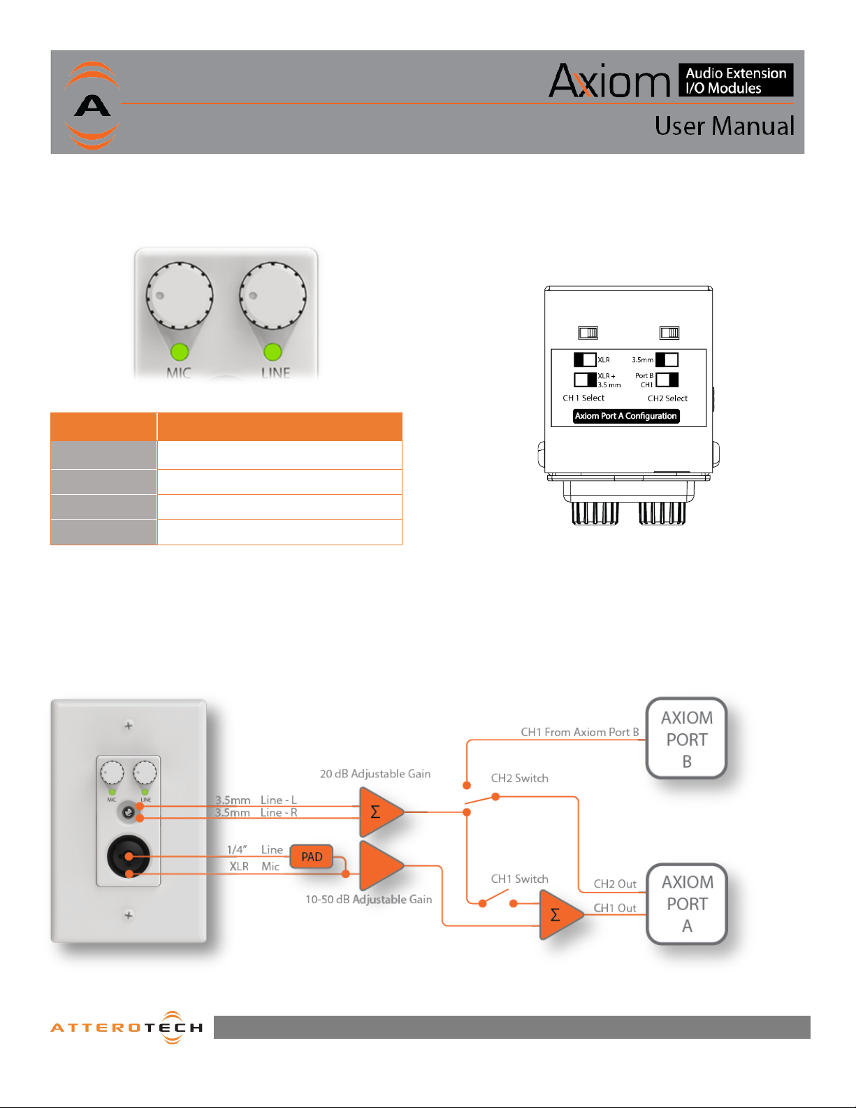
Figure 7 - Signal Flow
The ML1 is equipped with two LED indicators below the rotary
encoders for each the ¼”/XLR Mic input and the 3.5mm line input.
The following chart indicates the available LED status
information:
3.4 - Device Configuration and Workflow Overview
The ML1 may be configured for single use, or daisy-chained with
one other Axiom device.
The default configuration is for single device use with Port B
disabled and XLR enabled.
Figure 5 – LED Signal Metering
LED State Status
Off No signal present
Green -60 dBFS to < -20 dBFS
Yellow/Amber -20 dBFS to < -3 dBFS
Red -3 dBFS to 0 dBFS
Note: The full scale output of the Axiom bus is optimized for
+20dBu levels, so 0dBFS in terms of metering refers to +20 dBu
3.3 – Controls
The ML1 controls the desired input gain simply using the
coinciding input knob (see Figure 4). Turning the knob clockwise
raises the level, while counter-clockwise lowers.
Figure 6 - Switch Label/Config Options
The CH1 Select switches allows the integrator to route either the
XLR or a sum of the XLR and 3.5mm inputs to the CH1 output of
Axiom Port A.
The CH2 Select allows the integrator to route either the 3.5mm
input or the Axiom Port CH1 (daisy chained Axiom device) to the
CH2 output of Axiom Port A.
1315 Directors Row Suite 107 Fort Wayne, IN 46808 ⁞ (260)496-9668 ⁞ www.atterotech.com
Page 3
Page 9
4– AXP2O – Overview
4.2 – USB1 – Device Installation
The Axiom AXP2O provides analog audio output breakout,
power injection and control system connectivity to Attero
Tech’s Axiom endpoint products. The installer friendly form
factor allows it to be placed on an equipment rack shelf or
mounted to any flat surface.
Features:
o Analog Output - 2 Balanced line-level analog
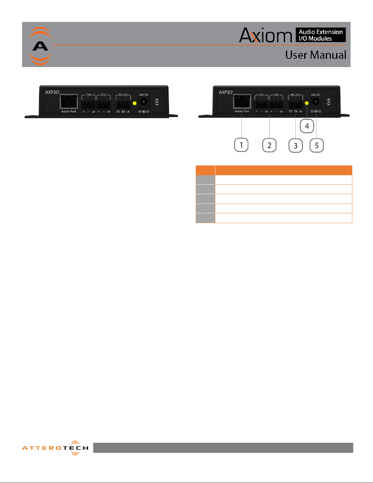
Figure 8 – AXP2O Front Panel
outputs for connectivity to mixers, amplifiers and
signal processors.
o Axiom port - Supports connectivity to any
Attero Tech Axiom endpoint.
o RS-232 - Provides RS-232 connectivity to control
systems for extending control to supported Axiom
products ( limited to one control enabled Axiom
endpoint on the Axiom bus)
o LED indication of power status
4.1 – AXP2O – What’s in the Box
The AXP2O comes supplied with the following:
o Axiom AXP2O device
o 24V AC/DC Power Supply
Figure 9 - Product Overview
ID Description
1 Axiom Port
2 Balanced Audio Output Terminal Blocks
3 RS-232 Terminal Block
4 Power Status LED
5 24V DC Power Input
1315 Directors Row Suite 107 Fort Wayne, IN 46808 ⁞ (260)496-9668 ⁞ www.atterotech.com
Page 4
Page 10
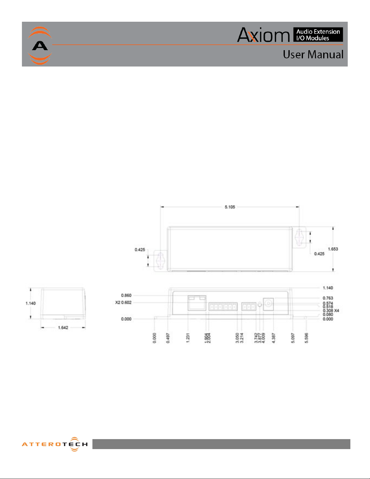
Figure 10 - AXP2O Dimensional Drawings
4.3 – Mounting
A typical installation will involve mounting an Axiom wall plate
into a pre mounted single-gang or larger wall box, standard
drywall bracket or mud ring. Before starting, make sure the wall
box where the Axiom device is to be installed is pre-wired with a
suitable unshielded CAT5/6 cable back to the AXP2O break out
box.
With the AXP2O powered off, attach the CAT cable from the
Axiom port of the AXP2O to the RJ45 on the Axiom device.
Apply power by plugging in the 24V DC power supply to the DC
power input on the AXP2O. The power LED on the AXP2O should
illuminate green. Additionally, the Axiom wall plate should also
start up and become ready to operate.
With the cable attached, carefully place the Axiom wall plate into
the wall box taking care to not trap the cabling. Once fully in
place, secure it with the screws provided. Once the unit is secured
in the wall box, fit the Decora plate over the front of the unit and
secure it with the screws provided with it. It is recommended to
not over-tighten the screws that attach the included Decora wall
plate to prevent cracking it.
*Note: CAD drawings can be downloaded from the Attero Tech
website. Please contact Attero Tech for any further product
related information that is not accessible on the website.
1315 Directors Row Suite 107 Fort Wayne, IN 46808 ⁞ (260)496-9668 ⁞ www.atterotech.com
Page 5
Page 11
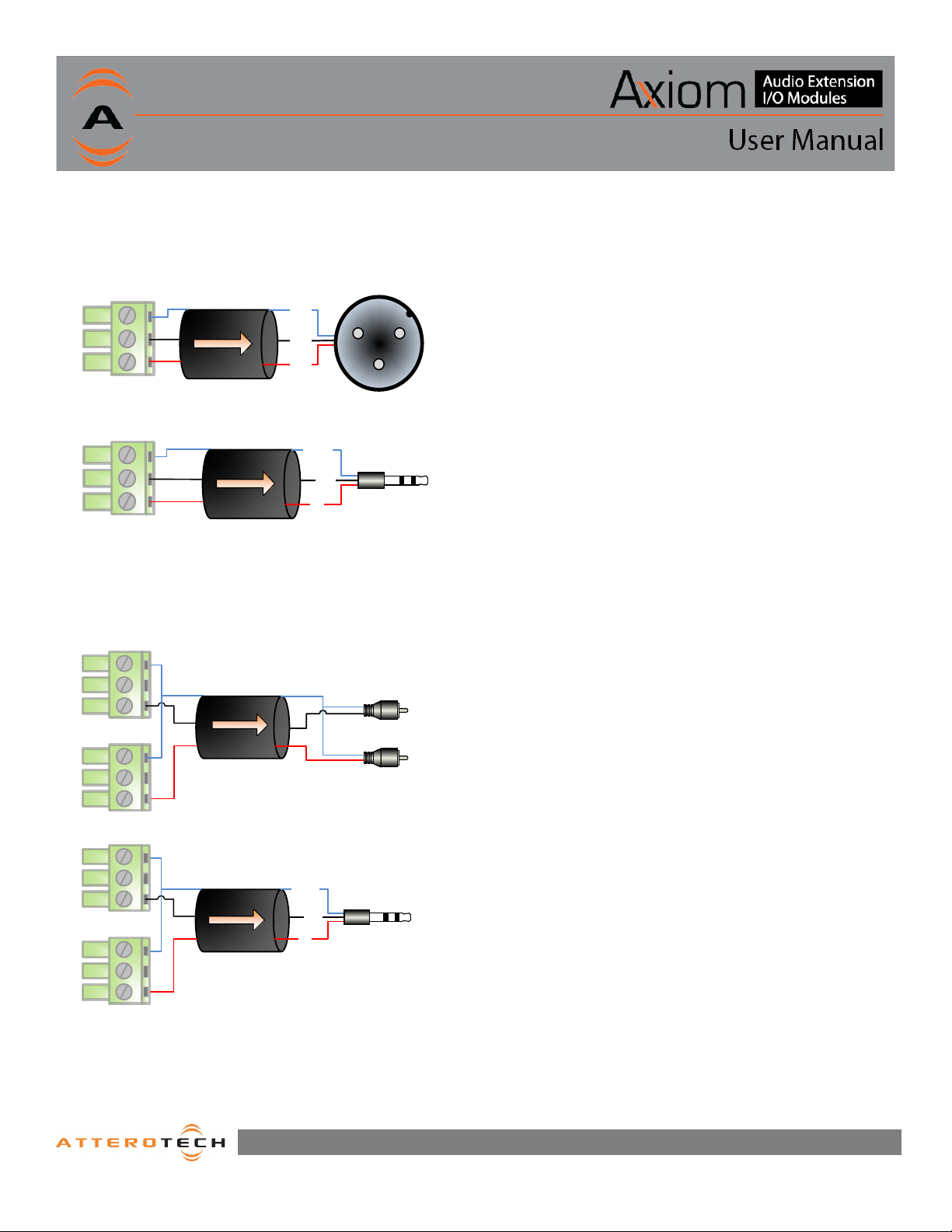
4.4 – Audio Connections
+
-
GND
Pin 1
Pin 3
Pin 2
1
1 2
3
XLR-M
2-Wire Cable + Shield
Or 3-Wire Cable
TRS Plug
+
-
GND
Sleeve
Tip
Ring
2-Wire Cable + Shield
Or 3-Wire Cable
TRS Plug
+
-
GND
Sleeve
Tip
Ring
Output 2
Output 1
+
-
GND
2-Wire Cable
+ Shield
2-Wire Cable
+ Shield
RCA (R)
+
-
GND
Tip
RCA (L)
Tip
Output 2
Output 1
+
-
GND
Sleeve
Sleeve
The AXP2O provides balanced audio outputs to external analog
audio equipment. Refer to the following diagrams for connecting
the outputs of the AXP2O to audio devices.
4.5 – 3rd Party Control
The RS-232 port on the AXP2O break-out box is intended for
connectivity to 3
of Axiom into professional AV applications.
rd
party control systems for extended integration
4.6 – RS-232 Interface
The RS-232 interface on the AXP2O is a pass through interface to
the Axiom port. Actual serial port settings can be found on select
Axiom products that support R2-232 control integration features.
Figure 11 - AXP2O to Balanced Input Wiring Guide
Figure 12 - AXP2O to Unbalanced Input Wiring Guide
1315 Directors Row Suite 107 Fort Wayne, IN 46808 ⁞ (260)496-9668 ⁞ www.atterotech.com
Page 6
Page 12

ARCHITECTS & ENGINEERS SPECIFICATION
ML1
The single gang mount interface unit shall have two potentiometers on the front panel for gain control of the 3.5mm input and the balanced
input independently.
The unit shall have a 3.5mm stereo consumer level input and a ¼”/XLR combo Mic/Line input. This input is amplified and sent to the Axiom
bus. The XLR input shall be dedicated for dynamic microphone signals, while the ¼” input may be used to interface balanced line level audio
sources to the Axiom bus.
The unit shall have selector switches for audio channel routing on the top of the unit.
There shall be two bi-color signal presence and level indicator LEDs on the front of the unit. One for the balanced input and one for the
3.5mm input.
The unit shall have two 8P8C RJ45 type connectors on the back side of the unit.
The unit shall support daisy chain of up to 1 other Axiom device, using 2 RJ45 (8P8C style connectors) for connectivity to CAT-X cabling.
The device shall support mounting the mounting of multiple units side by side in a multi-gang wall box or one unit in a single gang US wall
box.
The unit shall be the Attero Tech Axiom ML1 product.
AXP2O
The device shall have an 8P8C connector for connectivity to Axiom bus compatible products.
Two 3-position de-pluggable terminal blocks provide balanced analog audio breakout from the Axiom port for connectivity to the balanced
or unbalanced inputs of external audio equipment.
A single, 3-postion de-pluggable terminal block provides RS-232 pass through connectivity to the Axiom port
The 24VDC input provides power injection to the Axiom port/bus.
The interface shall be compliant with the RoHS directive.
The device shall be the Attero Tech Axiom AXP2O.
1315 Directors Row Suite 107 Fort Wayne, IN 46808 ⁞ (260)496-9668 ⁞ www.atterotech.com
i
Page 13
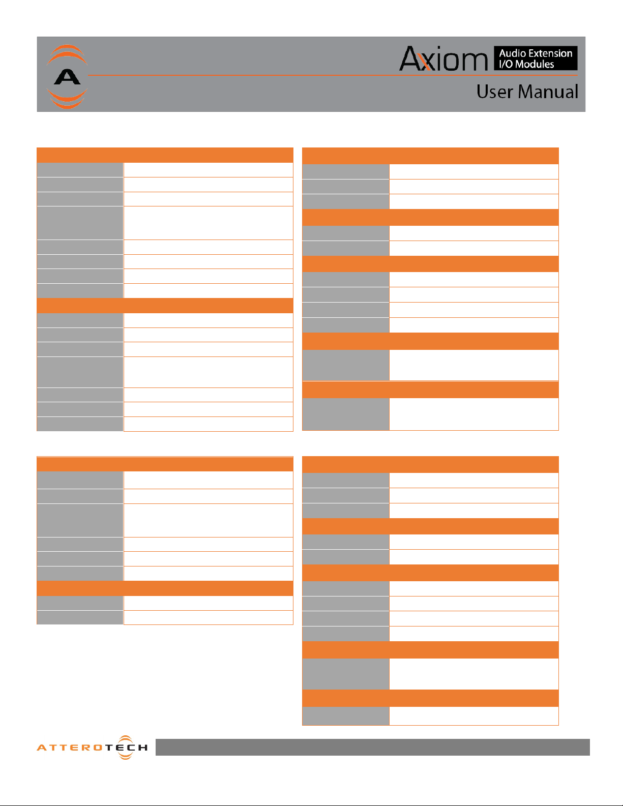
Device Specifications
REACH
REACH
ML1 Specs
Audio Inputs (Mic/Line)
Connector Type
Gain 0 to 50 dB
Input Imped ance >2kOhms at any gain (mic) >10kOhms Line
Maximum Input Levels
THD+N <0.05% @ 1 kHz, -3 dBFS input, 20-20kHz
Frequency Res ponse 20-20 kHz, +/- 1 dB (1/4”), 50-20kHz +/- 1 dB (X LR)
Dynamic Range >110 dB at minimum gain
EIN -115 dBu
Connector Type
Gain 0 to 20 dB
Input Imped ance >10K ohms at any gain
Maximum Input Levels +12 dBu @ minimum gain
XLR – ¼” Combo
+20 dBu @ minimum gain (XLR)
+18 dBu @ minimum gain (1/4”)
Audio Inputs (3.5 mm Line)
3.5mm TRS
Axiom
Physical L ayer Analog Audio, RS-232 Control, 24V DC Power
Connector (s) 8P8C
Cable Quality CAT-5e or better, UTP
Power Specifications
DC Power 24V DC (center positive barrel jack)
Power Consumption 50mA @ 24V / 1.2W
Physical Dimensions
Width 1.66”
Height 1.14”
Depth 2.35”
Weight 0.35 lbs.
Regulatory Compliance
Certificat ions
WEEE
RoHS
THD+N <0.05% @ 1 kHz, -3 dBFS input. 20-20kHz
Frequency Res ponse 20-20 kHz, +/- 1 dB
Dynamic Range >110 dB at minimum gain
AXP2O Specs
Audio Outputs
Connector Type 3.81mm, 3 position de-pluggable terminal blocks
Input Imped ance >2kOhms at any gain (mic) >10kOhms Line
Maximum Output Levels
THD+N <0.05% @ 1 kHz, -3 dBFS input, 20-20kHz
Frequency Res ponse 20-20 kHz, +/- 1 dB
Dynamic Range >100 dB
Connector Type 3.81mm, 3 position de-pluggable terminal blocks
Physical L ayer RS-232
+20 dBu
Control Port
Environmental Operating Specifications
Operating Te mperature
0 to 40° C
Axiom Port
Physical L ayer Analog Audio, RS-232 Control, 24V DC Power
Connector (s) 8P8C
Cable Quality CAT-5e or better, UTP
Power Specifications
DC Power 24V DC (center positive barrel jack)
Power Consumption <30mA @ 24V / 0.72 W
Physical Dimensions
Width 5.6”
Height 4.2”
Depth 1.66”
Weight 0.15 lbs.
Regulatory Compliance
Certificat ions
WEEE
RoHS
Environmental Operating Specifications
Operating Temperature
0 to 40° C
1315 Directors Row Suite 107 Fort Wayne, IN 46808 ⁞ (260)496-9668 ⁞ www.atterotech.com
ii
 Loading...