

Page 1

AT&T
MERLIN
Communications System
Models 1030 and 3070
With Feature Module 4
Administration Manual
®
Page 2

Table of Contents
How to Use This Manual
Administration Overview
Administering Your System for the First Time
Making Changes to Your System Later
MERLIN System Components
The Model 1030 Control Unit and Expansion
Unit
The Administrator/Attendant Console
Using the Console
Optional Equipment
Preparing to Administer Your System
The Square vs. Pooled Decision
About Square Systems
About Pooled Systems
The Forms and Labels You Need
Choosing a Time to Administer Your System
Basic Administration
Setting Your Control Unit
Changing Your System Later
Notes on Resetting Control Unit Switches
Entering and Leaving Administration Mode
Specifying Touch-Tone or Rotary Dialing
Setting Up Square Systems
Preparing to Assign Lines to Voice
Terminals
Assigning Lines to Buttons
Setting Up Pooled Systems
Preparing
Assigning
Preparing
set up
Assigning
Assigning
Access
Assigning
Customizing with Additional System Options
Assigning Call Restrictions to Voice Terminals
Assigning Outward and Toll Call
Restrictions
Setting Up Allowed Lists
Assigning Allowed-List Call Restrictions
Administering Automatic Route Selection
(ADS)
Preparing to Administer ARS Tables
Administering Area Code/Exchange Sections
of ARS Tables
Administering Pool Number and Other Digits
Sections of ARS Tables
Activating and Deactivating ADS
to Set Up Line Pools
Lines to Line Pools
to Assign Lines to Buttons and
Access to Line Pools
Individual Lines to Buttons
Line Pools to Buttons (Button
to Line Pools)
Dial Access to Line Pools
Page
12
12
13
14
14
17
20
20
21
22
24
24
25
26
27
27
29
31
31
32
33
36
37
38
40
41
42
44
45
46
46
52
53
54
Page
2
3
3
4
6
6
9
Assigning Voice Terminals to Groups for
Group Page
Establishing Night Service
Activating Night Service
Programming System Speed Dial Codes
Administering SMDR (Station Message Detail
Recording) Options
Setting Your Printer to Scroll to the Top of
the Page
Setting the Return Interval for Transferred
Calls
Programming Voice Terminals for Office
Priorities
Using Centralized Voice Terminal
Programming
Assigning an Automatic Line Selection
Sequence
Assigning Programmable Line Ringing for
Incoming Calls
Assigning Cover Buttons
Assigning Line Pickup Buttons
Programming Voice Terminals for Personal
Priorities
Assigning Features to Programmable Buttons
Feature Programming Chart
Assigning Personal Speed Dial Codes to 5-
and 10-Button Voice Terminals and Basic
Telephones
Using Special Characters in Programmed
Dialing Sequences
Selecting a Personalized Ring
Programming Voice Announcement Disable
Programming Simultaneous Voice and
Data Calls
Special Information about Attendant Consoles
Special information about 5-Button Voice
Terminals
Special Information about Basic Telephones
MERLIN System Features
Appendix: System and Voice Terminal
Configuration Forms
Index
Quick Reference Guide to Administration
Procedures
55
56
56
57
59
60
61
62
66
67
68
69
71
72
73
74
77
78
80
81
82
83
87
88
91
98
116
117
Page 3

How to Use This Manual
The advanced technology of the MERLIN™ communications system offers a flexibility that allows you to customize the system to your business communication needs.
As system administrator, you may be responsible for customizing your
system immediately after installation, and you will undoubtedly be the person to make
any necessary changes as your business needs change.
This administration manual takes you step by step through the procedures involved
in customizing your system. Here is how to use the manual:
If you are setting up a new system for the first time:
1.
Read the “Administration Overview,” page 3, to learn about the tasks you’ll
be performing as system administrator.
2.
Review the
with the equipment you’ll be working with.
3.
If you haven’t already decided which features you want your MERLIN
system to have, look through the
on pages 91 through 97.
4.
Get ready to administer your system by filling out the System and Voice
Terminal Configuration Forms on pages 98 through 115 and by reviewing
the information in “Preparing to Administer Your System,” page 13.
Read through "Basic Administration," page 21, and perform those tasks
5.
that apply to your particular system.
Similarly, work your way through “Customizing with Additional System Op
6.
tions,” page 40, adding features that fit your needs.
Review the features described in “Programming Voice Terminals for Of-
7.
fice Priorities,” page 62. Because these features have systemwide effects,
you should program the features on selected voice terminals yourself or
oversee any programming done by voice terminal users.
If you choose, further customize features on individual voice terminals by
8.
performing the procedures described in "Programming Voice Terminals
for Personal Priorities," page 72.
9.
To learn how to program your attendant console(s), review “Special Information about Attendant Consoles,” page 83.
10.
If you have many 5-button voice terminals or basic telephones connected
to your system, read “Special Information about 5-Button Voice Terminals,”
page 87, and "Special Information about Basic Telephones," page 88.
"MERLIN
System Components," page 6, to familiarize yourself
“MERLIN
System Features” described
MERLIN
If you are changing some options or features that are already in place:
1. Review the information in "Preparing to Administer Your System," page 13.
2. Using the Table of Contents, Index, or page references in
System Features,” page 91, locate the procedure for the option or feature
you want to change and perform the necessary steps in the procedure.
3. If you are making a basic modification to the system-that is, a modification that requires changing any of the switch settings on your control unit—
read the information in “Changing Your System Later,” page 24.
2
“MERLIN
Page 4

Administration Overview
Because the effects of system administration are wide-ranging, only you or someone
you delegate should perform administration procedures. The term administrator as used
in this manual refers to the act of establishing certain options and features that have
systemwide impact, such as assigning the outside lines that each voice terminal can
access or defining System Speed Dial codes for everyone in the system to use. You
use a particular voice terminal, the administrator/attendant console, and the switches
on your control unit to administer your system. However, before you can perform administration, you have to put the system in a special state of operation, called administration mode. (See “Entering and Leaving Administration Mode,” page 25, for
more information about this operating state.) In contrast, the term program refers to
assigning programmable features to an individual voice terminal. Anyone can put
a voice terminal in programming mode and assign it features while the system is in
the regular call-handling mode.
ADMINISTERING YOUR SYSTEM FOR THE FIRST TIME
System administration involves a series of simple procedures that you perform at
the control unit and at the administrator/attendant console (the voice terminal connected to the intercom 10 jack on the control unit). The MERLIN system is designed
to be up and running with a minimum amount of administration. However, depending on the conditions of your communications environment or the options you choose,
certain administration procedures may be required to set up a newly installed system.
Before attempting any other procedures, you must review the information in “Basic
Administration,” page 21, and complete the procedures that apply to your system
and business needs. Most administration procedures are optional, however, depending on which features you want to use in your business; these features are described
in “Customizing with Additional System options,” page 40. There are some features
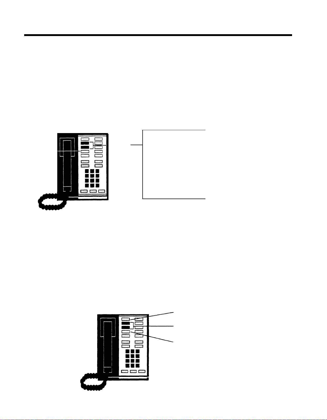
Model 1030 control unit
Voice terminal module
jack 10
Administrator/Attendant
console
Voice terminal module
jack 10
Model 3070 control unit
Administrator/Attendant
console
3
Page 5

There are some features that you may want to assign to certain voice terminals
yourself because they influence call-handling efficiency throughout your entire
business. Assigning these features does not involve administrative procedures, but
rather, simple programming procedures at individual voice terminals. These procedures are described in “Programming Voice Terminals for Office Priorities,” page
62. Finally, if you want to help people program their voice terminals to meet their individual needs, follow the procedures outlined in “Programming Voice Terminals for
Personal Priorities,” page 72. Later, if your needs change, you can always alter any
system administration or programming that has been done.
The chart which follows shows the five types of procedures described in this manual.
If you are about to perform system administration for the first time, be sure to read
“Preparing to Administer Your System,” page 13, before you attempt any procedures.
MAKING CHANGES TO YOUR SYSTEM LATER
Changes to system features that are administered from the administrator/attendant
console or programmed at individual voice terminals are easiest to implement. To
make these changes after your system has been set up, go to the section of this
manual that gives the procedure for assigning the feature or option you want, and
carry out just that procedure.
Basic changes to the way your system operates—that is, changes to the switch set-
tings on the control unit—may erase important system administration that is now in
place. Before you change any switch settings, review the information in “Changing
Your System Later,” page
24.
4
Page 6
Prepare for System Administration
These procedures help you get ready to administer your system.
●
Decide how people will access outside lines.
●
Complete and keep handy your System and Voice Terminal Configuration
Forms.
●
Schedule a time to perform administration procedures.
Perform Basic Administration
Depending on your system requirements, some of these procedures maybe
necessary immediately after your system is installed; you can also perform
these procedures whenever you need to change your system later. Perform
these procedures at the control unit and the administrator/attendant console.
●
Set your control unit.
●
Learn how to enter and leave administration mode.
●
Specify Touch-Tone or rotary dialing.
●
Set up a square system, with Iines assigned to buttons.
●
Set up a pooled system, with line pools, line-to-button assignments, and
either Button Access or Dial Access to Line Pools.
Customize with Additional System Options
These procedures are optional. Perform them at the administrator/attendant
console whenever you want to add these features to your system.
●
Assign tail restrictions.
●
Administer Automatic Route Selection.
●
Assign voice terminals to groups for Group Page.
●
Establish Night Service.
●
Program System Speed Dial codes.
●
Administer Station Message Detail Recording options.
●
Set return interval for transferred calls.
Program Voice Terminals for Office Priorities
These procedures are optional. Use Centralized Voice Terminal Programming
or perform them at individual voice terminals whenever you want to give someone access to these features.
●
Assign an Automatic Line Selection sequence.
●
Assign Programmable Line Ringing for incoming calls.
●
Assign Cover buttons.
●
Assign Line Pickup buttons.
Program Voice Terminals for Personal Priorities
These procedures are optional. Use Centralized Voice Terminal Programming
or perform them at individual voice terminals whenever you want to give someone access to these features.
●
Assign features to programmable buttons.
●
Assign Personal Speed Dial codes to 5- and 10-button voice terminals and
basic telephones.
●
Use special characters in programmed dialing sequences.
●
Select a Personalized Ring.
●
Program Voice Announcement Disable.
●
Program Simultaneous Voice and Data Calls.
5
Page 7
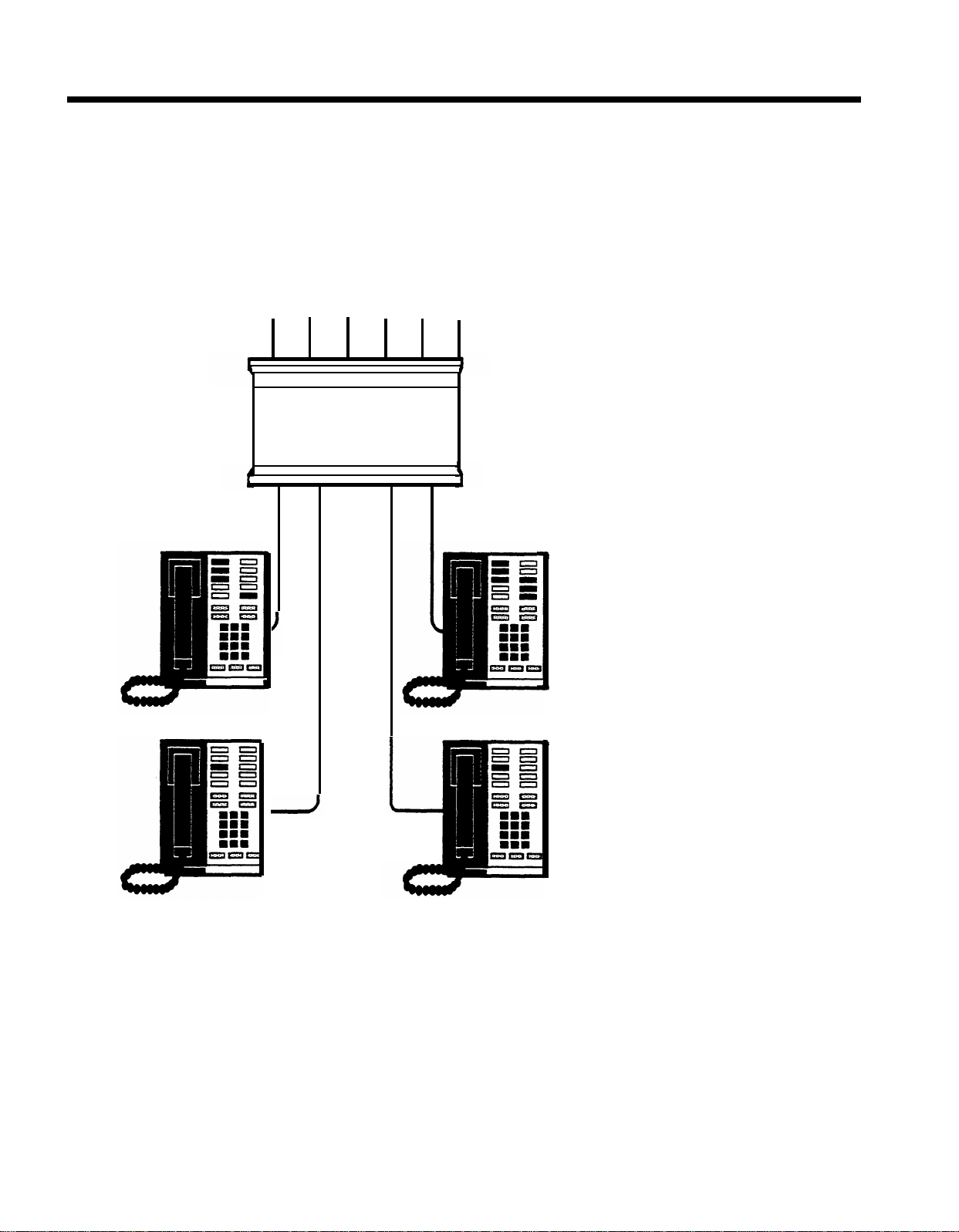
MERLIN System Components
When performing your administration tasks, you work with three components of the
MERLIN
system: the control unit,
the administrator/attendant console, and individual voice terminals. You may also have some optional equipment that
adds features and capabilities to your system but does not affect system administration. The following descriptions will
help you become familiar with the components that make up your system.
For information about system installation, refer to the Installation Guide: Models 1030 and 3070.
THE MODEL 1030 CONTROL UNIT AND EXPANSION UNIT
The Model 1030 control unit provides connections for up to 10 outside lines and 30 voice terminals, or for up to 15 outside lines and 20 voice terminals, depending on the combination of Line and Voice Terminal Modules you choose. For
a 1030 configuration, you have Line Modules in slots 7 and 8 (10 lines) and Voice Terminal Modules in slots 9, 10, and
11 (30 voice terminals). For a 1520 configuration, you replace the Voice Terminal Module in slot 11 with a Line Module.
This increases the number of lines to 15 and decreases the number of voice terminals to 20. The addition of an Expansion Unit makes the Model 1030 control unit a Model 3070 control unit and increases system capacity to up to 30 outside
lines and 70 voice terminals, again depending on the combination of Line and Voice Terminal Modules you choose.
THE MODEL 1030 CONTROL UNIT
1. Power Module: Reduces ac power to a level the
system can handle.
●
Circuit Breakers.
Automatically cut the power to
the control unit if an overload occurs.
Ring Generator jack.
●
Optional Ring Generator
Unit plugs in here if you have basic Touch-Tone
6
or rotary telephones.
●
Auxiliary Power connector.
Auxiliary Power
plugs in hereto provide the additional power for
systems with many optional accessories.
●
Power light.
●
On/Off switch.
Green light indicates power is on.
Turns the power to the control
unit on and off.
Unit
Page 8

Processor Module:
2.
Works in conjunction with
Feature Module 4 to control system operating
conditions.
●
Switches A, B, C, D, E, F, G,
and
H.
Selects
system options provided by Feature Module 4.
●
Warning light.
Red light warns of problem in
control unit. It also comes on for approximately
one minute when you first turn on the system.
Feature Module 4: Contains the software that con-
3.
trols your
MERLIN
system. You set eight switches on
the Processor Module, according to the labels on the
Feature Module, to select the following options from
the programs stored in Feature Module
Attendant/Administer (10) option.
●
4:
Selects attendant or administration mode of operation for
the administrator/attendant console.
Normal/Attendant (11, 12, 13, 14) options.
●
Select normal or attendant mode of operation for
these four voice terminals.
●
Pooled/Square option.
Selects mode of opera-
tion for the system so that line buttons on voice
terminals represent either groups of lines
(pooled) or separate lines (square). For detailed
information on this option, see "The Square vs.
Pooled Decision," page
Dial Access/Button Access option.
●
14.
Sets the
system so that line pools can be accessed at a
voice terminal by touching a button to which the
pool is assigned or by touching a Pool Access
button and then dialing the access code for that
line pool.
●
1-8 LineS/>8 Lines option.
Sets the system size
to eight or fewer outside lines (small system) or
to more than eight lines (large system).
Diagnostics Module (optional):
4.
Aids in identifying
faulty components if the system malfunctions.
SMDR (Station Message Detail Recording)
5.
Module: Allows connection of a printer so you can
print out call traffic reports automatically as calls are
made. You can also issue configuration reports
whenever you want them during administration
procedures.
Services Module (optional):
6.
Contains the following
jacks, switches, and adjusters to connect and control
optional equipment:
●
PFTT
(Power Failure Transfer Telephone) jack.
With an adapter, connects up to four standard
modular telephones for use as backup during
commercial power outage. The system
automatically switches service to them if power
fails.
Extra Alert jacks.
●
Three jacks connect strobe
lights, loud bells, or horns for three noisy or
remote zones where the regular voice terminal
ring cannot be heard.
Page jack.
●
Connects a loudspeaker paging
system. With an adapter, you can have up to
three paging zones.
Music-In jack.
●
Connects a music source for
Music-on-Hold or background music through a
paging system.
●
Bkgd Vol (Background Volume) control.
Allows
volume adjustment for background music.
MOH Vol (Music-on-Hold Volume) control.
●
Allows volume adjustment for Music-on-Hold.
Page Sgnl switch.
●
On (up) provides a short tone
before loudspeaker paging announcements. Off
(down) eliminates the signal.
●
Level switch.
Sets amplification for music
source. Hi (down) is for sources with their own
amplifiers; Lo (up) is for those without.
Line Module:
7.
Provides jacks for up to five outside
lines. Normally, there are two Line Modules in the
Model 1030 control unit. You may have a third,
however, if you decide to replace the Voice Terminal
Module normally found in slot 11 with a
in order to have 15 lines instead of 10 (1520 configuration). If you add an Expansion Unit,
Line Module
you will not need
this extra line capacity, and you can return your control unit to the 1030 configuration.
The Expansion Unit contains up to four Line Modules.
These modules, combined with two Line Modules in
the 1030 control unit, provide the system maximum of
six Line Modules (30 lines).
●
Jacks 0, 1, 2, 3, 4.
MERLIN
system. Line Modules have letters as
Connect outside lines to the
well as numbers. For example, the first Line
Module in the control unit is lettered A, so the
jacks in that Line Module are called A0, A1, A2,
A3, and A4.
Voice Terminal Module:
8.
Provides jacks for ten voice
terminals. You may have up to three Voice Terminal
Modules for the Model 1030 control unit and up to four
additional Voice Terminal Modules in the Expansion
Unit. A Basic Telephone Module with jacks for basic
Touch-Tone or rotary telephones is also available.
●
“O” begins the numbering for the first five voice
terminal jacks on the module. These jacks (and
the location of the module) determine the intercom numbers of the voice terminals plugged into them. For example, if a Voice Terminal Module
is plugged into the slot labeled “intercoms
20-29,” the jack labeled “O” is for intercom 20.
The jack below it is for intercom
●
“5” begins the numbers for the second five voice
21, and so on.
terminals.
Module C (optional):
9.
An Off-Premises Telephone In-
terface to support off-premises telephones.
7
Page 9
Addition of the Expansion Unit changes the Model 1030 control unit to a Model 3070 control unit and increases overall
system capacity to 30 lines and 70 voice terminals. The unit can accommodate:
●
Up to two Power Modules
●
Up to four Line Modules
●
Up to four Voice Terminal Modules
The second Power Module is required for systems with more than 20 lines or more than 60 voice terminals. The Expansion Unit also has two additional module slots for future use.
NOTE: If you add an Expansion Unit to a system configured for 15 outside lines and 20 voice terminals, you must remove
the Line Module from slot 11 and replace it with a Voice Terminal Module. This returns your system to the standard configuration of 10 outside lines and 30 voice terminals. You can then insert modules into the appropriate slots in the Expansion Unit.
If Expansion Unit slots 17, 18, 21, 22, and 23 are empty, the power switch on the first Power Module (slot 16) must be
set to Off (left). If modules are inserted in any of these slots, the power switch must be set to On (right).
If Expansion Unit slots 19,20, and 24 are empty, the power switch on the second Power Module (slot 27) must be set
to Off (left). If modules are inserted in any of these slots, the power switch must be set to On (right).
Circuit Breakers
Circuit Breakers
5 5 5
5
5
1
2
3
4
5
1
1
2
2
3
3
4
4
5
5
1
2
3
4
5
5
5
5
Power
On
Off
EXPANSION UNIT FOR MODEL 1030
8
Page 10

THE ADMINISTRATOR/ATTENDANT CONSOLE
The administrator/attendant console is the voice terminal connected to the intercom
10 Voice Terminal Module jack in the control unit. The console operates in either of
two ways:
●
It functions as your primary attendant console under ordinary day-to-day
conditions.
●
It functions as the administrator console when it is used to perform many of the
procedures explained later in this manual.
To change the administrator/attendant console from one mode of operation to the
other, you simply set a switch on the control unit and then set another switch on the
console itself. When the console is in administration mode, some of its buttons take
on different functions than they do when the console is in the regular call-handling
mode. Therefore, when you administer the system, you insert a special set of ad-
ministration mode button labels in the console so that you know which buttons to
touch. You will find two sets of button labels, one for a small console and another
for a large console, in the back of this manual. (See page 25 for procedures for chang-
ing modes.)
The type of administrator/attendant console you have depends on the size of your
system. In systems with 20 or fewer voice terminals and eight or fewer lines (small
systems—switch H on the control unit set to 1-8 Lines), the administrator/attendant
console is a 34-button deluxe voice terminal. Only a 34-button deluxe model is suitable
for administering small systems because it has lights next to each programmable
button. You use the lights to keep track of what is happening on the lines and voice
terminals you are working with.
In systems with more than eight lines or more than 20 voice terminals (large
systems-switch H on the control unit set to > 8 Lines), the administrator/attendant
console consists of a 34-button deluxe voice terminal with an attached Attendant In-
tercom Selector. Only this type of console is suitable for administering a large system
because some aspects of administration require the use of the Attendant Intercom
Selector. Lights on the Attendant Intercom Selector also help you keep track of the
system’s status. For example, whenever you are administering your system, the light
Message Status
beside
must be off.
Small and large consoles with administration mode button labels are illustrated on
pages 10 and 11.
9
Page 11
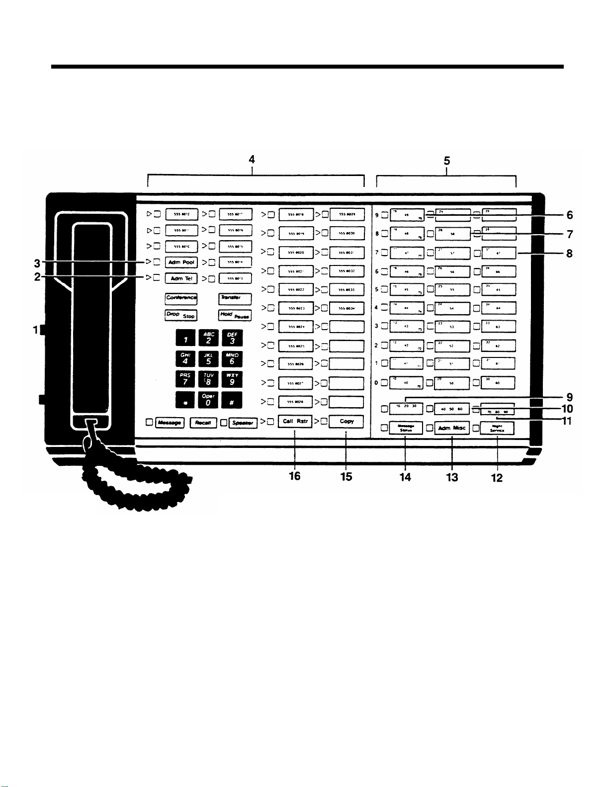
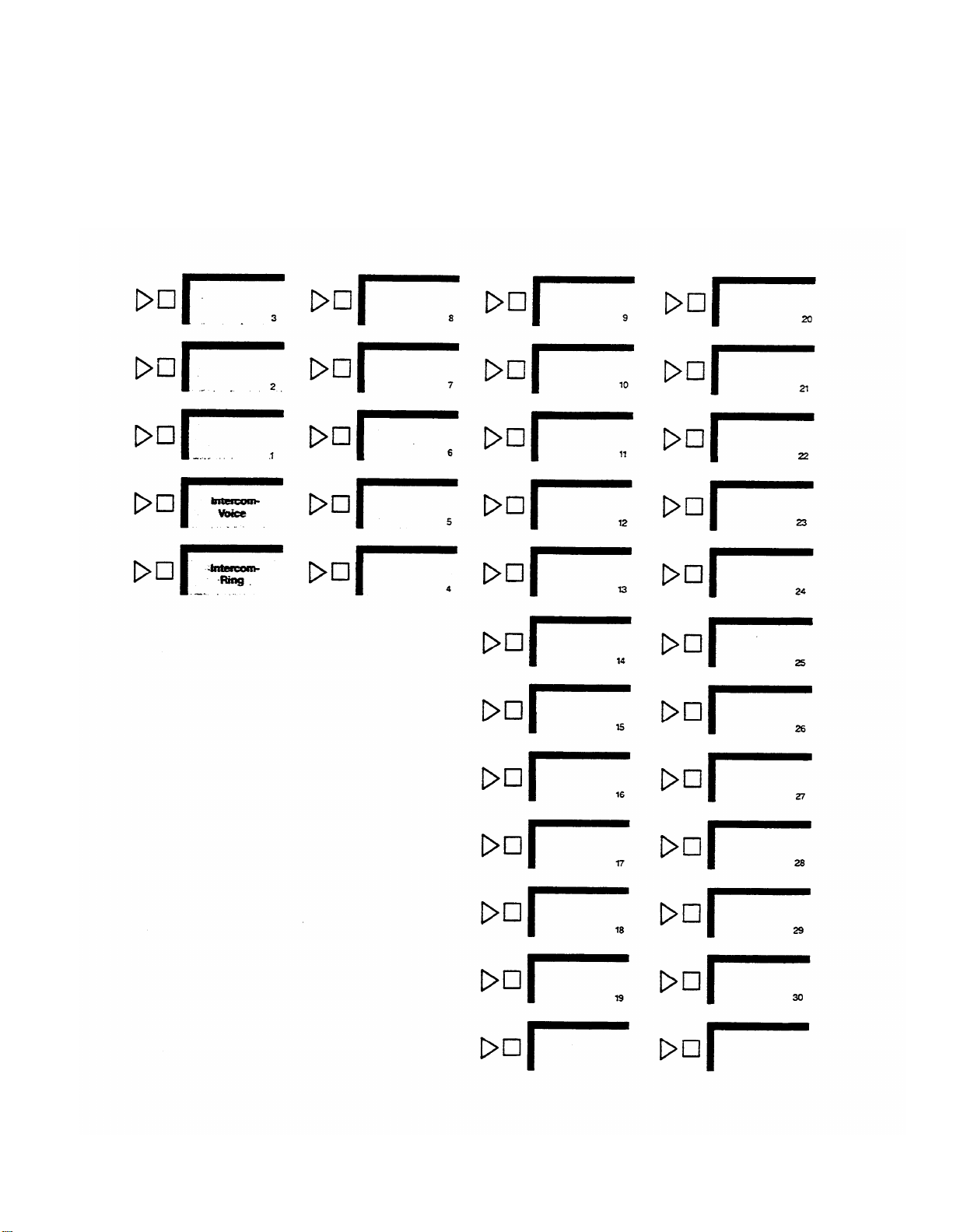
Small Administrator/Attendant
Console* in Administration Mode
1.
You set the T/P switch to P to perform system
administration.
2.
You use
minals and assigning voice terminals Dial Access to
Line Pools.
3.
You use
4.
Line buttons.
5.
Auto Intercom buttons (10 through 29).
6.
You use
10
Adm Tel
Adm Pool
Adm Misc
* For systems with 8 or fewer lines and with 20 or fewer voice terminals—switch
when assigning lines to voice ter-
when setting up line pools.
when specifying Touch-Tone or
rotary dialing, assigning allowed-list call restrictions,
and administering other system options.
7.
You use
tivate extra-alerting devices when the attendant is off
duty.
8.
You use
assignments as one that has already been set up.
9.
You use
prefix or area code only and when assigning outward
and toil call restrictions to voice terminals.
Night Service
Copy
Call Rstr
when assigning lines to ac-
to give a voice terminal the same
when setting lines to detect a toll
H
on control unit is up.
Page 12
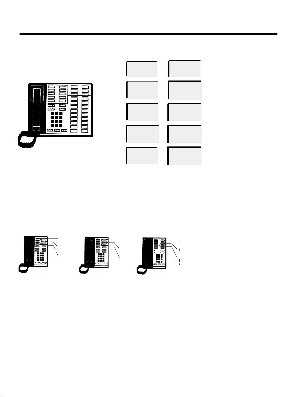
Large Administrator/Attendant
Console* in Administration Mode
The large console provides the same features as the small console, but
it
has more line and Auto Intercom buttons.
You use this Shift button to use Auto Intercom but-
9.
1.
You set the T/P switch to P to perform system
administration.
You use
2.
minals and assigning voice terminals Dial Access to
Line Pools.
You use
3.
4.
Line buttons.
Auto Intercom buttons (10 through 79).
5.
Buttons in this column represent intercom numbers
6.
10-19,40-49, or 70-79, depending on which Shift but-
ton you touch.
7.
Buttons in this column represent intercom numbers
20-29 or 50-59, depending on which Shift button you
touch.
Buttons in this column represent intercom numbers
8.
30-39 or 60-69, depending on which Shift button you
touch.
* For systems with more than 8 lines or more than 20 voice terminals—switch H on control unit is down.
Adm Tel
Adm Pool
when assigning lines to voice ter-
when setting up line pools.
tons for intercom numbers 10-39.
10.
You use this Shift button to use Auto Intercom but-
tons for intercom numbers 40-69.
You use this Shift button to use Auto Intercom but-
11.
tons for intercom numbers 70-79.
12.
You use
tivate extra-alerting devices when the attendant is off
duty.
13.
You use
rotary dialing, assigning allowed-list call restrictions,
and administering other system options.
14.
You don’t use
ministration. The light beside Message Status must
be off during administration.
15.
You use
assignments as one that has already been set up.
You use
16.
prefix or area code only and when assigning outward
and toll call restrictions to voice terminals.
Night Service
Adm Mist
Copy
Call Rstr
when specifying Touch-Tone or
Message Status
to give a voice terminal the same
when setting lines to detect atoll
when assigning lines to ac-
during system ad-
11
Page 13

Using the Console
When you administer your system, you frequently use the Auto Intercom buttons and
Shift buttons (large systems only) on the administrator/attendant console. The
paragraphs below describe how to use these buttons.
Auto Intercom Buttons
Each person’s voice terminal has a unique 2-digit intercom number similar to an ex-
tension number. These intercom numbers (10 through 39 for a Model 1030 system,
10 through 79 for a Model 3070 system) are automatically assigned to Auto Intercom
buttons on the console. During system administration, you use the lights next to each
Auto Intercom button to determine the status of voice terminals in your system.
Shift Buttons (large systems only)
The large console has three Shift buttons that enable you to administer as many as
70 voice terminals by using only the 30 Auto Intercom buttons on the Attendant lntercorn Selector. When you touch one of the Shift buttons, you change the intercom
numbers assigned to the Auto Intercom buttons. Use the left Shift button labeled
10-20-30 to select intercom numbers 10 through 39 in the blue band, the center Shift
button labeled 40-50-60 to select intercom numbers 40 through 69 in the white band,
and the right Shift button labeled 70-80-90 to select intercom numbers 70 through
79 in the gray band. If you want to dial a particular intercom number, you must first
touch the Shift button that provides access to the group of intercom numbers that
includes the one you want. For example, if you want to assign lines to the voice terminal represented by intercom 31, touch the left Shift button. The light next to the
Shift button comes on, and the Auto Intercom buttons now represent intercom
numbers 10 through 39.
Message Status Button (large systems only)
The Message Status button is used only when your console is in the attendant mode.
You use this button to find out which voice terminals have messages waiting for them.
OPTIONAL EQUIPMENT
You may also have optional equipment that adds features and capabilities to your
system.
Attendant Intercom Selector.
●
Provides an attendant with 70 Auto intercom
buttons.
Basic Telephone and Modern Interface.
●
munication devices such as autodialers, answering machines, cordless
Connects telephones and data com-
telephones, facsimile machines, and auto-answer or originating modems to your
MERLIN
system. You can also use a transformer to connect a timer to a Basic
Telephone and Modem interface.
●
Basic Telephone Module.
telephones to the
Hands-Free Unit.
●
MERLIN
Provides you with full speakerphone capability including
Lets you connect basic Touch-Tone and rotary
system.
hands-free telephone conversation, On-Hook Dialing, Monitor-on-Hold, and
teleconferencing.
●
Headset and Headset Adapter.
Enables an attendant to answer and listen to
calls without lifting the handset.
General Purpose Adapter
●
(only for use with 10-button and 34-button voice ter-
minals). Enables you to connect accessories, such as data terminals, cordless
telephones, and autodialers, to a
Off-Premises Telephone Interface.
●
MERLIN
system.
MERLIN
system voice terminal.
Connects off-premises telephones to your
12
Page 14

Preparing to Administer Your
System
Before you start to administer your system, review this section to make sure you have
the information and completed forms that you need.
Preparation Procedures
●
Decide how people will access outside lines.
●
Complete your System and Voice Terminal Configuration Forms.
●
Schedule a time to perform administration procedures.
.
13
Page 15

THE SQUARE VS. POOLED DECISION
For systems that have just been installed, you have to make a decision about a basic
system characteristic-how people access outside lines with their voice terminals.
You have the option of setting your system to be either square or pooled. In a square
system, each outside line can appear on a separate button at each voice terminal.
In a pooled system, outside lines are grouped together so that one button provides
access to several outside lines. On attendant consoles, however each outside line
appears on a separate button, whether your sytem is pooled or square, and you cannot change this arrangement.
Whether your system should be square or pooled depends on your specific business
needs. If you want to use the Automatic Route Selection feature, your lines must be
pooled and your system must be set for Dial Access to Line Pools (Dial Access is
discussed on page 79). The characteristics of both configurations are discussed in
greater detail in the paragraphs that follow.
About Square Systems
In the
MERLIN
4, a square configuration is one in which outside lines are represented by separate
buttons on every voice terminal
communications system, Models 1030 and 3070 with Feature Module
in the system. A square configuration simplifies call-
handling because people can join in on calls or pickup calls on hold just by touching
the appropriate line button at almost any voice terminal.
You can choose between two kinds of square configurations: standard or custom-
ized. in the standard configuration, you give all voice terminals in the system access
to the same lines. In the customized arrangement, on the other hand, you assign
specific lines or sets of lines to selected groups of voice terminals. You can also assign
personal lines to individual voice terminals in a customized square configuration.
Standard Square Configurations
The standard square configuration is ideal for offices in which all staff members use
the same lines to make and receive calls. In this arrangement, every line in the system
appears at each voice terminal that has enough buttons to accommodate that number
of lines. Depending upon the size of your system, you can assign up to 30 lines to
as many as 70 voice terminals.
You will assign each of your lines to the same buttons at each voice terminal. To get
the most from a standard square configuration, all your voice terminals should have
enough buttons to handle all the lines in your system. If you have smaller capacity
voice terminals, see “Special Information about 5-Button Voice Terminals,” page 87.
An example of a standard square configuration appears on the following page. All
six lines in the system are available for general use and appear on the same buttons at each voice terminal, as shown.
14
Page 16

B
A
c
D
E
F
I
I
I
●
Lines A, B, G D, E, F
Lines are assigned to the same buttons at each voice terminal.
EXAMPLE OF STANDARD SQUARE CONFIGURATION
Pages 27 through 30 explain how to assign lines to buttons on voice terminals in a
standard square configuration.
Customized Square Configurations
In a customized square configuration, you assign individual lines or groups of lines
to selected voice terminals with similar requirements for placing and receiving calls.
This arrangement lets you tailor your communications system to meet the needs of
different departments. It also simplifies recordkeeping on calling patterns within your
business.
The departments at a car dealership, for example, may have different calling needs.
Say that Ultimate Motors has eight local lines, three WATS lines, and one Foreign
Exchange (FX) line. The sales and office staff use the out-f-state WATS line frequently
to speak with manufacturers’ representatives, haulers, and other dealerships. This
group uses one of the in-state WATS lines to contact customers, vendors, and the
Division of Motor Vehicle Registration in the state capital. The third WATS line is an
incoming in-state WATS line used by customers who live outside the immediate area.
The service staff doesn’t usually have to make long distance calls. However, one major
equipment supplier is located 25 miles away, and calls to this supplier would normally be toll calls. To reduce this expense, Ultimate has a Foreign Exchange line for
the supplier’s exchange code, 560. When the service staff uses this line, calls to the
supplier are treated as the equivalent of local calls. Because the manager handles
many confidential negotiations over the telephone, he requires a personal line.
15
Page 17
A customized square configuration is the most appropriate system arrangement for
Ultimate Motors’ varied communication requirements. The administrator assigns the
three WATS lines and three of the eight local lines to the sales and clerical staff. The
service department voice terminals get three different local lines and the Foreign
Exchange line. The seventh local line is assigned to the voice terminal at the parts
desk, and the eighth is assigned as a personal line at the manager’s voice terminal.
The figure below illustrates this type of configuration.
Telephone Lines of Automobile Dealership
BDFHJL
I
G
A
E
C
K
l
Service
(Lines A, B, C, D)
I
I
I I
●
l
Sales and office
(Lines F, G, H, 1, J, K)
Parts
(Line E)
EXAMPLE OF CUSTOMIZED SQUARE CONFIGURATION
Manager
(Line L)
As the figure shows, this type of system provides complete flexibility in line assignment. You can assign lines to any available buttons on a voice terminal, in any order
you wish. A person in a customized square system does not have to have a line
assigned to his or her voice terminal in order to answer a ringing, parked, or held
call on that line. Say that a customer calls on the in-state WATS line to ask if Ultimate
has a particular gasket in stock. The salesperson who receives the call notifies the
parts desk of the call. The parts clerk can use the Line Pickup feature described on
page 71 to answer the call. If a voice terminal in the service area is ringing and nobody
is free at the moment to answer it, someone in the adjacent office area can use the
Call Pickup feature described on page 76 to answer the call.
Pages 27 through 30 explain how to assign lines to buttons on voice terminals in a
customized square configuration.
16
Page 18
About Pooled Systems
In a pooled configuration, you group several outside lines together into a pool that
people can access with a single button on their voice terminals. When they place
a call, they either touch the button assigned to a particular line pool (Button Access
to Line Pools) or touch a Pool Access button and dial the code of the pool best suited
for this type of call (Dial Access to Line Pools). The system then selects a free line
from that pool, and the user dials the number he or she is trying to reach. If your
system has Automatic Route Selection, users simply touch a Pool Access button and
dial the number. The system routes the call automatically to the most appropriate
pool available for that type of call, following the order of preference setup by you,
the administrator.
Your system can have as many as 11 different line pools. Each type of special-purpose
line that your business has, such as WATS or Foreign Exchange (FX) lines, should
be assigned to a separate pool. You should not mix types of lines in a pool, because
you cannot control which line people get when they access the pool. If your business
has local lines, in-state WATS lines, and Band 1 out-of-state WATS lines, for example, you must set up at least three line pools.
you
When assigning lines in a pooled system,
can assign all, some, or none of your
lines to a single pool (see diagram below), but you cannot assign any line to more
than one pool. By the same token, you do not need to assign all your lines to pools;
you can also assign individual lines that are not included in any pool to any voice
terminal in your system. A diagram of a pooled system with eight lines appears on
the following page.
Line B Line D
Line A
I I I
Line C
●
Lines A, B, C, D, E pooled
Lines A, B, C, D, E
Intercom-Voice
Line E
SIMPLE POOLED SYSTEM
17
Page 19
Line C
Line B Line G
Line H
Attendant console
Line not assigned to pool = Line D
Line pool 3
Main pool
lntercom-
Voice
Main pool
Line pool 2
Line pool 3
Line A
Intercom
Voice
Intercom
Ring
= Lines A, B, C
= Lines E, F
= Lines G, H
Line D
Main pool
Intercom-
Voice
Line F
Line E
Line D
Line pool 2
Main pool
lntercomVoice
Voice terminal 1
Voice terminal 2
POOLED SYSTEM WITH 8 LINES
Voice terminal 3
Line use is very efficient in a pooled system, so you may need fewer outside lines
than you would with a square system. Furthermore, more programmable buttons on
voice terminals are available for assignment as special-purpose line buttons or
feature buttons.
18
Page 20
Button Access vs. Dial Access to Line Pools
You can choose one of two access options for line pools: Button Access to Line Pools
or Dial Access to Line Pools. Because you set a switch for this option on your control
unit, the method you select will be used at all the voice terminals in your system.
If you have only one or two line pools, Button
Access is the best option
for your system.
if your system has several line pools, however, Dial Access is preferable because
it provides access to all pools using only two buttons on each voice terminal. If you
want to use Automatic Route Selection, you must select Diai Access. Diai Access
is also necessary if you want basic telephones to have access to line pools or special
lines or if you want 5-button voice terminals to have access to more than one special
pool.
IntercomVoice
DIAL ACCESS TO POOLS
Pools
Dial code 893
Dial code 892 =
Dial code 891 = Line pool 3
Dial code 890 = Line pool 2
Dial code 9 =
= Line pool 5
Line pool 4
Main pool
Assume that you have five line pools. With the Dial Access option (seethe diagram
above), you arrange the system so that people can access any line pool by lifting
the handset, touching one of the two buttons above Intercom-Voice, and dialing the
access code assigned to the pool (9 for the main pool or 890 through 899 for the
others). Even if you set your system for Dial Access, you can still assign some pools
to particular buttons, if you like.
With the Button Access option (see the diagram below), people access all line pools
directly through pool buttons on each voice terminal. in such an arrangement, the
first two buttons above
Intercom-Voice
provide access to the main pool. You may
assign additional buttons for access to other pools that may include WATS lines, FX
lines, or lines used for special purposes.
Additional
line pool
Main
pool
Intercom-Voice
BUTTON ACCESS TO POOLS
19
Page 21

THE FORMS AND LABELS YOU NEED
Before you begin performing administration procedures, be sure to complete all the
necessary forms:
A
System Configuration Form to keep a record of how the lines in your system
●
are arranged.
●
Voice Terminal Configuration Forms to record the lines and features assigned
to all voice terminals. Fill out one of these for each voice terminal.
-
When you ordered
completed the
your system, you should have filled out these forms when you
MERLIN
Communications System Planning Guide: Models 7030 and
3070. If you did not, turn to the Appendix, copy the forms included there, and fill them
out before you proceed further. These forms serve as important references’
throughout later system administration procedures.
.
During system administration the buttons on the administrator/attendant console per-
form completely different functions than they do when the console is being used to
handle calls. Therefore, you need a different set of button labels whenever you use
the console for system administration. There are two sets of administration mode
button labels in the back of this manual: one set for a small administrator/attendant
console (systems with switch H on the control unit set to 1-8 Lines) and another set
for a large administrator/attendant console (systems with switch H set to >8 Lines).
Fill in the appropriate set for your system, and keep the labels and completed forms
to use whenever you administer your system.
CHOOSING A TIME TO ADMINISTER YOUR SYSTEM
Before you begin administration procedures, choose a time when you do not expect
many people to be using their voice terminals. When you perform some administra-
tion procedures, the system blocks all calls on the lines or voice terminals with which
you are working. Blocked voice terminals generate soft, periodic beeps to alert people that they cannot be used. If you accidentally try to administer a voice terminal
that has an active call, you do not cut off the caller. Rather, you are unable to continue administering that voice terminal until it is idle.
20
Page 22

Basic Administration
Once your system planning and paperwork are complete, you can perform basic administration procedures. The chart below lists the procedures described in this sec-
tion. Remember that if you are administering a new system that has just been in-
stalled, some of these basic procedures maybe required to set the proper operating
conditions for your particular environment, and you must perform them first before
you goon to do any other system administration. Carry out the procedures in the
order listed in the chart, but keep in mind that you may not need to perform all of them
to customize your system to your particular environment. Read each procedure first
to see if it applies to you.
IMPORTANT:
Administer your system at a time when you do not expect many peo-
ple to be using their voice terminals.
Basic Administration Procedures
●
Set your control unit.
●
Learn how to enter and leave administration mode.
●
Specify Touch-Tone or rotary dialing.
●
If you have a square system, assign lines to buttons on voice terminals.
●
If you have a pooled system, set up line pools, assign individual lines and
line pools to voice terminals, and establish Button Access to Line Pools
or Dial Access to Line Pools.
21
Page 23

SETTING YOUR CONTROL UNIT
The first step in customizing the
MERLIN
system is to set the control unit to the
operating conditions you select.
IMPORTANT If your control unit has been set previously and you just want to
change the setting of a particular switch, be sure to read "Changing Your
System Later," page 24, before resetting the switch.
Follow these steps to set your control unit:
1.
Turn off the control unit by setting the On/Off switch on the Power
Module to Off.
2.
Set switch A which is located in slot 2 (color-coded purple) on the Processor Module, to Administer (down).
Switch A controls intercom number 10, which is always the main attendant position. Set switch A to the Administer position whenever you need
to administer your system from the administrator/attendant console.
When you finish administering, set switch A to Attendant (up).
NOTE:
Switch A, which sets the mode of the administrator/attendant
console, is the only switch on the control unit that you can reset with
the power on. If you reset any other switch with the power on, the con-
trol unit does not record any of the changes you make until you turn the
power off, then on again.
3.
Set switches B through E.
Switches B through E control intercom numbers 11 through 14, respec-
tively. These consoles normally function as voice terminals, but you can
designate any of them as backup attendant consoles. If you designate
a voice terminal to function as an attendant console, each outside line
appears on a separate button, regardless of whether you select the
pooled or square option.
The four voice terminals selected by switches B through E plus the
administrator/attendant console (intercom number 10) provide a maximum of five attendant consoles if you need them.
For those voice terminals that function as attendant consoles, set
●
the switch to Attendant (down).
●
For those voice terminals that function as regular telephones, set
the switch to Normal (up).
4.
Set switch F.
If you have chosen to pool your lines, set switch F to Pooled (up)
and go to step 5.
lMPORTANT
lf you are resetting this switch from Square to Pooled,
be aware that you erase all system line administration and voice
terminal programming that is now in place.
If you want every outside line to appear on a separate button, set
switch F to Square (down). The eight lines plugged into jacks A0
through B2 appear automatically on all non-attendant voice terminals. Go to step 6.
22
Page 24

5. Set switch G.
NOTE:
The instructions that follow apply if switch F is set to Pooled. If
switch F is set to Square, switch G may beset to either position without
having any effect on the system.
If you have decided to arrange your pooled system so that people
●
can access line pools directly by simply touching the associated
button on a voice terminal, set switch G to Button Access (down).
●
If you have decided to arrange your pooled system so that people
can access any line pool by dialing the pool’s access code, set
switch G to Dial Access
(up). You
must set switch G for Dial Access
if you want to use Automatic Route Selection. Even if you set your
system for Dial Access to Pools, you can still program buttons at
individual voice terminals to provide one-touch access to particular
line pools.
6. Set switch H.
●
If you have eight or fewer outside lines and 20 or fewer voice ter-
minals, set switch H to 1-8 Lines (up).
NOTE:
The switch setting you select does not always have to correspond to the number of outside lines you actually have. For example, if you have eight or fewer lines but plan to grow beyond eight
lines within a year or two, you might prefer to set switch H to>8
Lines (down) in order to simplify administering the system later. If
you change the setting of this switch later, you cancel any special
line administration of programmed features on your attendant
consoles.
If you have more than eight outside lines or more than 20 voice ter-
●
minals, or if you expect your system to grow to this size in the next
year or so, set switch H to >8 Lines (down).
7. If your system has an SMDR (Station Message Detail Recording)
Module and a printer with an RS-232 connector, connect the printer to
the SMDR Module (refer to the instructions that come with the module).
8. Turn on the control unit by setting the On/Off switch on the Power
Module to On (right). This causes the system to record the changes you
just made. The warning light on the module will go on. Wait for the light
to go off before continuing. If you have a printer hooked up, a page
header will be printed.
9. If your system has a Services Module, make the following adjustments.
Otherwise, go to step 10.
If you have background music through a loudspeaker paging
●
system, you can adjust its volume by turning the Bkgd Vol control
clockwise to raise the volume, or counterclockwise to lower it. If
you do not have background music through a loudspeaker paging system, turn the control counterclockwise as far as it goes.
●
If you have Music-on-Hold, you can adjust its volume by turning
the MOH Vol control clockwise to raise the volume, or
counterclockwise to lower it. If you do not have Music-on-Hold, turn
the control counterclockwise as far as it goes.
●
If you have a music source with its own amplifier, set the Level
switch to Hi (down); otherwise, set the switch to Lo (up).
●
If you have a loudspeaker paging system and want a short tone
to precede loudspeaker announcements, set the Page Sgnl switch
to On (up). Otherwise, set the switch to Off (down).
10. If you are setting up a new system for the first time, enter administration mode, as described on page 25, and continue following the pro-
cedures in this section.
23
Page 25

CHANGING YOUR SYSTEM LATER
Basic changes to the way your system operates—that is, changes to the switch settings on the control unit—may erase important system administration that is now in
place. To change switch settings, turn to "Setting Your Control Unit," page 22, and
follow the instructions for the switch you want to reset. Since
you won’t
be performing the entire procedure, be especially careful not to skip any steps that are required.
Follow the general instructions below to prevent this from happening.
General instructions for resetting control unit switches:
1. Set the On/Off switch on the Power Module to Off.
2. Set switch A to Administer (down).
3. Follow the instructions for the switch you intend to reset.
4. Turn the On/Off switch on the Power Module to On.
5. Perform any required readministration or reprogramming discussed
below in “Notes on Resetting Control Unit Switches.”
6. Set switch A back to Attendant (up).
Notes on Resetting Control Unit Switches
Whenever you change the setting of a switch on the control unit, you will probably
have to make other changes in your system. Keep the following in mind:
If you add or remove attendant consoles (switches B through E), you have to
●
reassign special lines and features to the voice terminals whose function you
have just changed.
If you change the setting of the Pooled/Square switch (switch F), you erase all
●
system line administration and voice terminal programming that was formerly in
p/ace. You have to completely readminister all your lines; set up pools and Dial
Access to Line Pools, if these apply; and reprogram all your voice terminals.
If you change the setting of the Dial Access/Button Access switch (switch G),
●
you must reprogram individual voice terminaIs accordingly. The system will
automatically assign a different function to the two buttons above
Voice.
You must assign line pools to particular buttons (Button Access) or give
lntercom-
the voice terminal access to specified line pools (Dial Access). You must also
assign individual lines to buttons.
●
If you change the setting of the 1-8 lines/>8 lines switch (switch H), you cancel
any special line administration or programmed features on your attendant con-
soles. The setting of this switch determines how the system automatically
assigns lines and intercom numbers to the buttons on attendant consoles. it
also determines the function of certain buttons on the attendant/administrator
console when the console is in administration mode. (See “Initial Feature
Assignments for Attendant Consoles,” pages 85 and 86.)
setting you select does not always have to correspond to the number of outside
lines you actually
have. For example, if you have eight or fewer lines but plan
Note that the switch
to grow beyond eight lines within a year or two, you might be wise to set switch
H to >8 Lines in order to simplify administering the system later.
24
Page 26
ENTERING AND LEAVING ADMINISTRATION MODE
Administration mode is an operating state of your control unit and of your
administrator/attendant console that is very different from their everyday state of
operation. With the system in administration mode, you are able to set up or change
systemwide options or features. When you finish using the administrator/attendant
console to administer your system, you must leave administration mode to resume
normal attendant operations.
You must enter administration mode to set up a new system and again each time
you use the attendant console to administer your system. The boxed instructions
below tell you how to enter administration mode.
-
Entering Administration Mode
1.
Switch A is located on the Processor Module (slot 2, color-coded purple)
of the control unit. Set Switch A to Administer (down).
Insert the administration mode button labels provided at the back of this
2.
manual in the administrator/attendant console. Different sets are provided
for large and small systems.
If the light next to
3.
Message Status
is on, touch it once to turn it off before
beginning to administer your system (large systems only).
4.
Slide the T/P switch on the left side of the console to P.
On small consoles, red and green lights start flashing next to the administration mode buttons labeled
Adm Pool, Adm Tel, Adm Mist, Call Rstr,
and
Night Service. On large consoles, red and green lights start flashing next
to the buttons labeled
next to the buttons labeled
Adm Pool, Adm Tel,
Adm Mist
and
and
Night Service.
Call Rstr.
Green lights flash
When you finish administration procedures at the console, you must leave administration mode to resume normal operation. Do this when you complete your initial system
administration and whenever you complete any system changes in the future. The
boxed instructions below tell you how to leave administration mode.
Leaving Administration Mode
1. Slide the T/P switch to the center position.
2. Set switch A on the Processor Module of the control unit to Attendant (up).
3. Remove the administration mode button labels from the console and insert the regular call-handling labels used by the attendant.
25
Page 27

SPECIFYING TOUCH-TONE OR ROTARY DIALING
When your system is installed, it is set to generate Touch-Tone signals. If some of
your lines are rotary, you need to reset your system accordingly. If you have rotary
lines or if you are not sure what type of lines you have, follow the procedure below.
If all your lines are Touch-Tone, turn to the next page to continue administering your
system.
To determine if your lines are Touch-Tone or rotary, go to the administrator/attendant
console and make sure that the T/P switch is in the center position. Then touch each
line button and dial out. If a line is Touch-Tone, you hear tones and the dial tone stops.
If a line is rotary, you hear tones but the dial tone is not interrupted. Follow the procedure below to specify Touch-Tone or rotary dialing.
you have not already
1. If
done so, enter administration mode by following the
boxed instructions on page 25.
2. Touch
Adm Misc.
The lights next to the administration mode buttons stop flashing, and the
green light next to
Adm Mist
remains on.
3. Dial the 4-character code #302.
4. One by one, touch the line button for each line in your system until the green
light beside it shows the appropriate code. Each successive touch of a but-
ton gives you one of the following codes:
Steady green on = Touch-Tone dialing
rotary signaling
5. Touch
Adm Misc
Green off =
again.
The lights next to the administration mode buttons flash.
6. Continue to administer your system or leave administration mode by follow-
ing the boxed instructions on page 25.
26
Page 28

SETTING UP SQUARE SYSTEMS
In square systems, individual lines appear on separate buttons at voice terminals.
you
want a standard square system, you will give all your voice terminals access
If
to the same outside lines and assign the lines to the same buttons at every voice
terminal. If you prefer a customized square system, you can assign different lines
or groups of lines to selected voice terminals, in whatever order you want. If someone
routinely carries on private telephone conversations, you may want to assign a personal line to his or her voice terminal as part of your customized square setup. A personal line will not ring at the attendant’s console and cannot be picked up at any other
voice terminal in your system.
The information that follows describes how to assign lines to buttons in square
systems. (See page 14, “The Square vs. Pooled Decision,” for more information on
square systems.)
Before you assign lines to buttons, please read the following information:
Even though you may not be using the full capacity of a Line Module in the con-
●
trol unit,
all
five of the lines that would be represented by that module are
automatically assigned to buttons on the administrator/attendant console. A port
with no line cord plugged into it is called a nonequipped line appearance or
“ghost line.” Remove any ghost lines from your administrator/attendant console
so that these buttons can be used for custom features. If you have a small console and are not using the full capacity of a Line Module in the control unit, you
should also remove ghost lines from your voice terminals.
●
The Initial Feature Assignments diagrams on pages 85 and 86 illustrate the order
in which lines are assigned to buttons on the administrator/attendant console
when your system is first set up. The system automatically assigns lines to the
buttons in the order in which the lines are plugged into the control unit. This is
the “default” arrangement, what your system does unless you specify something
different. You can follow the procedure below to assign lines to buttons in a different order.
●
When you assign a line to a voice terminal, the system automatically assigns
the line to the first button that doesn’t already have a line assigned to it, in the
order shown in the diagram on the next page. You can assign lines to voice ter-
minals in a different pattern by touching the line buttons in the order in which
you want them to appear.
●
Note that none of the voice terminals in your system come with preprinted button labels. Be sure to label the voice terminal buttons with the telephone
numbers of the lines you assign.
●
Always assign lines to one voice terminal at a time.
Make sure you have a completed Voice Terminal Configuration Form for each
voice terminal.
●
Remember that voice terminals cannot be administered and used at the same
time. You cannot assign lines to a voice terminal unless it is idle, and the user
cannot place or receive calls while you are assigning lines. While you are administering a voice terminal, it beeps softly as a reminder that it cannot be used.
Preparing to Assign Lines to Voice Terminals
If you want to have a standard square system and have eight or fewer lines, your
system has already been set up for you. The system automatically assigns the lines
plugged into control unit jacks AO through B2 to the eight line buttons above the dial
pad on each voice terminal. If you have more than eight lines, however, you must
follow the procedure below to assign the rest of your lines to each voice terminal in
your system. The lines will be assigned to buttons in the order in which you touch
them.
27
Page 29
Order in Which the System Assigns Lines
in a Square System
28
Page 30

If you are setting up a customized square system for the first time, you should begin
by removing all existing lines from each voice terminal in your system. If the primary
attendant needs to have access to all general-use lines, remove only those lines that
you are reserving for personal use from the administrator/attendant console. Follow
the procedure below to assign lines to buttons on the voice terminals in your system.
Remember that the lines will be assigned to buttons in the order in which you touch
them.
Assigning Lines to Buttons
To assign individual lines to buttons in a standard or customized square system, follow
the procedure below.
1.
If you have not already done so, enter administration mode by following the boxed instructions on page 25.
2.
Touch
Adm Tel.
The lights next to the administration mode buttons stop flashing, and the
green light next to
3.
Dial the intercom number (14, for example) or touch the Auto Intercom
Adm Tel
remains on.
button for the voice terminal to which you want to assign lines.
If the voice terminals idle, a steady green light comes on next to its Auto
Intercom button, and the system gives a 2-beep signal for you to begin.
If the voice terminal is being used, the green lights next to the
Intercom button and
Adm Tel
flash rapidly. You must wait until the green
Auto
lights become steady or try again later. If you try to assign a line to a
busy voice terminal, you will hear a beep and will not be able to proceed.
4.
Refer to the Voice Terminal Configuration Form to see which lines to
assign to this voice terminal. (If you plan a standard square configuration, you will be assigning all your Iines to every voice terminal.) Steady
green lights come on next to any lines already assigned to the voice
terminal.
5.
Touch the appropriate line buttons to add or remove lines from this voice
terminal. The green light next to each line button tells you the current
status of the line. Each successive touch of a line button gives you one
of the following codes:
Green light on =
Green light ofl =
line is assigned to this voice terminal
line is not assigned to this voice terminal
The order in which you touch the line buttons determines the order in
which lines appear on the voice terminal. For example, assume that
eight lines (lines AO through B2) are already assigned to the voice terminal you are administering, and you want to add eight more. If you
touch the line buttons in the order in which they appear on the
administrator/attendant console (B3, B4, CO, etc.), they will appear in
the same order on the voice terminal. However, if you touch the button
for line C4 first, that line will appear on the first available button on the
voice terminal. If you touch the button for line CO next, line CO will appear on the button below the line C4 button, and so on. Be sure that
the correct telephone number for each line appears on the associated
button on the voice terminal.
29
Page 31

6. Repeat steps 3 through 5 for each voice terminal to which you want to
assign lines.
NOTE:
If you are setting up a customized square system, try to admin-
ister groups of voice terminals that share the same line assignments
at the same time. If you plan to assign a personal line to a voice terminal,
be sure not to assign the line to any voice terminals that should not have
access to that line.
You can use the shortcut below to give another voice terminal the same
line assignments as one you have already set up. This procedure is
especially timesaving if you have a standard square system, since all
your voice terminals will have the same line assignments.
NOTE When you copy line assignments, you also copy restrictions and
allowed-list permissions.
●
Dial the intercom number or touch the Auto intercom button of the
new voice terminal.
●
Touch
●
Copy.
Dial the intercom number or touch the Auto intercom button of the
original voice terminal.
7. Touch
Adm Tel.
The lights next to the administration mode buttons flash again.
8. Continue to administer your system or leave administration mode by
following the boxed instructions on page 25.
30
Page 32

SETTING UP POOLED SYSTEMS
In pooled systems, you group similar types of outside lines into a pool that people
can access with a single button on their voice terminals. For example, you might group
five local lines into one pool, three in-state WATS lines into a second pool, and two
cross-country WATS lines into a third pool. This would free up several buttons on voice
terminals that would otherwise be required for individual lines. If you decide to set
up a pooled system, you will probably want to pool ail your lines except single, specialpurpose lines and those that are needed as personal lines.
To setup a pooled system, you begin by assigning lines to pools. Next, you assign
individual lines to buttons on voice terminals. If your system has Button Access to
Line Pools, you also assign selected pools to particular buttons. If your system has
Dial Access to Line Pools, you give each voice terminal access to the pools the user
needs.
The following sections describe how to setup a pooled system. (See “The Square
14,
vs. Pooled Decision,” page
for more information about pooled systems.)
Preparing to Set Up Line Pools
If you plan to pool the lines in your system, you must first assign individual lines to
the appropriate pools. Before you set up your line pools, please read the informa-
tion below.
Even though you may not be using the full capacity of a Line Module in the con-
●
trol unit, the lines that would be represented by that module are automatically
assigned to buttons on the administrator/attendant console. A port with no line
cord plugged into it is called a nonequipped line appearance or “ghost line.”
Remove any ghost lines from the buttons to which the system assigned them
so that these buttons can be used for custom features. If you have eight or fewer
lines, you may also have to remove ghost lines from your voice terminals.
●
You cannot set up line pools unless all the voice terminals in your system are
idle. Once you touch
Adm Pool
and see the steady green light that indicates
you are free to administer your system, the system cannot receive incoming tails.
Any callers will get a busy signal.
●
Whenever you set switch F on the control unit to Pooled, the system automatically
assigns all your lines to the main pool. Local lines should remain in the main
pool, but all other lines can be removed. You can assign lines that you do not
want in the main pool to other pools or use them as individual lines.
Do not mix different types of lines. For example, do not put regular telephone
●
lines and WATS lines in the same pool. Even within a WATS line pool, you can-
not mix different bands of WATS lines or include both inbound and outbound
lines. All lines in a pool must be interchangeable, since you cannot control which
lines people will get when they use the pool.
●
The number of lines available for pooling is affected by the number of lines you
must reserve for personal or special-purpose use. For example, if you have ten
outside lines and two people need personal lines, there are eight lines left for
pooling. if a line is assigned to a pool, it cannot be assigned to a second pool
or as an individual line.
●
You can have up to 11 pools, with as many lines as you like in each pool. if you
have Dial Access to Line Pools, people can access a particular pool by dialing
the code assigned to the pool (9 for the main pool, 890 through 899 for additional pools).
3
Page 33

Assigning Lines to Line Pools
Follow the procedure below to set up line pools.
1. If you have not already done so, enter administration mode by following the boxed instructions on page 25.
2. Touch
Adm Pool.
If your lines aren’t in use, the lights next to the administration mode buttons stop flashing, the green light next to
Adm Pool
remains on, and the
console gives a 2-beep signal for you to begin.
If this happens, go to step 4. If not, go to step 3.
3. If the green light next to
Adm Pool
flashes instead of remaining on and
you don’t hear a 2-beep signal, your lines are in use. You cannot set up
line pools unless all the voice terminals in your system are idle. To find
out which voice terminals are busy, set the T/P switch to the center
position.
Steady green lights show next to the Auto Intercom buttons for terminals
that are in use.
If you want to proceed with setting up line pools, return the T/P switch
to P touch
console gives the 2-beep signal for you to begin. Go on to step
NOTE:
Adm Pool
again, and wait. As soon as the system is idle, the
4.
If someone is on a data call, his or her voice terminal will not
show a busy signal. However, you will not be able to proceed with setting up line pools until that voice terminal is idle.
4. When you enter administration mode and touch
Adm Pool,
the system
puts you in the main pool, the one that must contain your local lines.
The main pool is Pool 9. Refer to your System Configuration Form to
review the numbers that you assigned to the rest of your line pools. You
must dial these access codes (890 through 899) in order to administer
each of your line pools.
NOTE:
If a line appears as an individual line at a voice terminal in your
system, it will disappear from that terminal if you add it to a line pool.
Before adding lines to pools, make sure they are not needed as in-
dividual lines.
If you want to administer the main pool, go on to step 5. If you want to
administer one of your other pools, dial the access code for that pool,
then goon to step 5.
5. Steady red lights appear beside each line that is assigned to this pool.
Refer to your completed System Configuration Form to see which lines
you want to have in the pool.
6. Touch the button of any line whose pool assignment you want to change.
Each touch of the button gives you one of the following codes:
Steady red light on =
line is assigned to pool
Red light off = line is not assigned to pool
32
NOTE:
If you hear a beep, the line is already in another pool. You must
remove the line from its current pool, by dialing that pool’s access code
and touching the line button, before you can assign the line to this pool.
7. To administer another pool, dial the appropriate access code (9 or 890
through 899) and repeat steps 5 and 6.
8. To make sure that your line pools are setup as you want them, dial the
access code of each line pool in turn and verify that the steady red lights
are on next to the correct line buttons.
9. Touch
Adm Pool.
The lights next to the administration mode buttons flash again.
10. Continue to administer your system or leave administration mode by
following the boxed instructions on page 25.
Page 34

Preparing to Assign Lines to Buttons and Set Up Access to Line Pools
You can assign individual lines and line pools to particular buttons on voice terminals
and remove them from buttons whenever necessary. You can also assign individual
voice terminals Dial Access to selected line pools. Before you begin assigning lines
and line pools to buttons on voice terminals or assigning voice terminals Dial Access to Line Pools, please read the following information.
NOTE:
Dial Access to Line
are presented on page 38.
If you plan to use Automatic Route Selection, you must set your system for
Pools. The procedures for setting up Dial Access to
Always assign lines and line pools to one voice terminal at a time.
●
Make
sure you have a completed Voice Terminal Configuration Form for each
Line Pools
voice terminal.
The Initial Feature Assignments diagrams on pages 85 and 86 illustrate the order
●
in which lines are assigned to buttons on attendant consoles when your system
is first set up. The system automatically assigns lines to the attendant console
in the order in which the lines are plugged into the control unit. This is the
“default” arrangement, what your system does unless you specify something
different. You can change the order in which lines appear on the console by
following the procedure given below.
Each line in your system must appear on a separate button at attendant con-
●
soles. If you assign a line pool to an attendant console, your system automatically
assigns all the lines to buttons in the order in which they appear in the line pool.
Be aware that you may change the positions of your lines on the attendant console when you assign line pools.
●
For example, say that you setup two pooils. Pool 9 contains lines 1,3, and 4 and
Pool 890 contains lines 2, 5, and 6. Lines 1 through 6 initially appear on your
attendant console in numerical order. If you assign Pool 9, then Pool 890 to the
attendant console, however, the lines will appear in this order: 1, 3, 4, 2, 5, 6.
If you change your line order by assigning pooled lines to attendant consoles,
be sure to relabel your buttons to show the correct line numbers. If you remove
a pool from the attendant console, remember that you remove all the lines in
that pool.
Remember that voice terminals cannot be administered and used at the same
●
time. You cannot assign lines and line pools to a voice terminal unless it is idle,
and the user cannot place or receive calls while you are assigning lines. The
voice terminal beeps softly while you are administering it as a reminder that it
cannot be used.
When you assign a line to a voice terminal, the system automatically assigns
●
the line to the first button that doesn’t already have a line assigned to it, in the
order illustrated in the diagram on the following page. You can assign lines to
voice terminals in a different pattern by changing the order in which you touch
the line buttons. The procedures that follow show how to assign lines to buttons on voice terminals in whatever order you prefer.
33
Page 35

Order in Which the System Assigns Lines
in a Pooled System
34
Page 36

Note that none of the voice terminals in your system come with preprinted but-
●
ton labels. Be sure to label the buttons with the correct numbers for the individual
lines and line pools that you assign to the voice terminal.
If you set switch G on your control unit for Button Access to Line Pools, the system
●
automatically assigns Pool 9, the main pool, to the two buttons above lntercomVoice on voice terminals. if you set your system for Dial Access to Line Pools,
the system automatically assigns these two buttons as dial access buttons. People will touch one of these buttons before dialing the number of the poo they
want to use.
When you assign a line in a pool to a particular button on a voice terminal, you
●
assign all the lines in that pool to that button. Therefore, if
a certain pool,
such as a WATS line pool, to a separate button, you can do so
you want to assign
by assigning any line in the pool to the button. You can do this whether switch
G is set to Button Access or Dial Access.
●
If someone regulariy covers calls that come in on another person’s line (for example, a secretary who answers someone’s personal line), try to assign that line
to both people. if you can’t, use a Cover button (see page 69). Keep in mind,
however, that a Cover button covers all calls that come in on the covered voice
terminal, not just calls on a specific line.
The procedures that follow show how to assign individual lines to buttons and how
to administer either Button Access or Dial Access to Line Pools. At this point, you
should have decided which individual lines to assign to each of your voice terminals.
if you selected Button Access to line pools, you also need to know which pools you
want to assign to each voice terminal. Be sure you have a completed Voice Terminal
Configuration Form for each voice terminal you will be administering.
35
Page 37

Assigning Individual Lines to Buttons
To assign individual lines to buttons:
1. If you have not already done so, enter administration mode by following
the boxed instructions on page 25.
2. Touch
Adm Tel.
The lights next to the adrninistration mode buttons stop flashing, and the
green tight next to
Adm Tel
remains on.
3. Dial; the intercom number (15, for example) or touch the Auto Intercom button for the voice terminal to which you want to assign lines.
If the voice terminal is idle, a steady green light comes on next to its Auto
Intercom button, and the system gives you a 2-beep signal to begin.
If the voice terminal is being used, the green lights next to the Auto Inter-
com button and
Adm Tel
flash rapidly. You must wait until the green lights
become steady or else try again later. If you try to assign lines to buttons
at a busy voice terminal, the system will beep and you will not be able to
proceed.
4. Refer to the Voice Terminal Configuration Form to see which individual
lines should be assigned to this voice terminal. Steady green lights show
next to any lines currently assigned to the voice terminal. Steady red lights
show next to all lines contained in any system pool.
5. To add a line to or remove a line from this voice terminal, touch the button
for that line. The green light next to the line button tells you its current status.
Each touch of the line button gives you one of the following codes:
Green light on =
Green light off =
line is assigned to the voice terminal
line is not assigned to the voice terminal
The order in which you touch the buttons during administration determines
the order in which lines appear on the voice terminal. For example, sup-
pose that you have three individual lines to assign to a voice terminal that
has Dial Access to Line Pools. These lines appear in alphabetical and
numerical order on your administrator/attendant console, as shown on
pages 85 and 86. If you touch the button for line B2 first, it will be assigned
to the first available position on the voice terminal, in this case the top button in the first column above the dial pad. If you touch the button for line
Al next, it will be assigned to the next available position, the bottom but-
ton in the second column. Touching the button for line AO will assign that
line to the next available button, the button above the line Al button.
NOTE:
If you plan to assign a personal line to a voice terminal, be sure
not to assign the line to any voice terminals that should not have access
to that line.
6. Repeat steps 3 through 5 for each voice terminal in your system.
If you want to give a voice terminal the same line assignments as one that
is already set up, use this shortcut:
NOTE:
When you copy line assignments, you also copy call restrictions,
Dial Access to Line Pools, and allowed-list permissions.
●
Dial the intercom number or touch the Auto Intercom Button of the
new voice terminal.
●
Touch
●
Dial the intercom number or touch the Auto Intercom button of the
Copy.
original voice terminal.
7. Touch
Adm Tel.
The lights next to the administration mode buttons flash again.
8. Continue to administer your system, or leave administration mode by
following the boxed instructions on page 25.
36
Page 38

Assigning Line Pools to Buttons (Button Access to Line Pools)
If you have few line pools and do not use Automatic Route Selection, you will probably
prefer to set your control unit and administer your voice terminals for Button Access
to Line Pools. Remember that if you select Button Access, it will apply to all voice
terminals in your system. Your system will automatically assign the main pool to the
two buttons above Intercom-Voice on each voice terminal.
To assign a line pool to a button:
1. If you have not already done so, enter administration mode by following the boxed instructions on page 25.
2. Touch
Adm Tel.
The lights next to the administration mode buttons stop flashing, and the
green lights next to
Adm Tel
remain on.
3. Dial the intercom number or touch the Auto Intercom button for the voice
terminal to which you want to assign line pools to buttons.
If the voice terminal is idle, a steady green light comes on next to its Auto
Intercom button, and the system gives you a 2-beep signal to begin.
If the
voice terminal is
Intercom button and
being used, the green lights next to its Auto
Adm Tel
flash rapidly. You must wait until the green
lights become steady or try again later.
4. Refer to the Voice Terminal Configuration Form to see which line pools
should be assigned to this voice terminal. Green lights show next to the
buttons of any lines already assigned to this voice terminal. Red lights
show next to the line buttons for each line in any system pool.
5. Touch the button of any line in the line pool you want to add to or remove
from this voice terminal. Each successive touch of the line button gives
you one of the following codes:
line pool is assigned to a button
= line pool is not assigned to a button
NOTE:
Green light on =
Green light off
The system automatically assigns the main pool to the two but-
tons above the Intercom buttons, and you cannot change this assign-
ment. The system automatically assigns the other line pools to buttons
in the order illustrated on page 34. To change the order in which pools
other than the main pool appear on the voice terminal, remove all lines
and line pools assigned to the voice terminal, following the procedure
given above. Then touch the line buttons in the order you want the individual lines and line pools to appear on the voice terminal.
If you’re readministering a system, and you don’t know the order in
which lines and pools appear on the voice terminal, remove all the individual lines and line pools and reassign them.
6. Repeat steps 3 through 5 for each voice terminal in your system.
If you want to give a voice terminal the same line pool assignments as
one that has already been set up, use this shortcut:
NOTE:
When you copy pool assignments, you also copy call restric-
tions, Dial Access to Line Pools, and line assignments.
Dial the intercom number or touch the Auto Intercom button of the
●
new voice terminal.
●
Touch
Copy.
●
Dial the intercom number or touch the Auto Intercom button of the
original voice terminal.
7. Touch
Adm Tel.
The lights next to the administration mode buttons flash again,
8. Continue to administer your system, or leave administration mode by
following the boxed instructions on page 25.
37
Page 39

Assigning Dial Access to Line Pools
If you have a pooled system and switch G on the control unit is set to Dial Access
(up), you can assign individual voice terminals Dial Access to selected line pools.
With this arrangement, a person can access any line pool by touching the Pool Access
button and dialing the access code for the pool (9 for the main pool or 890 through
899 for additional pools).
If you plan to use Automatic Route Selection, you must use Dial Access to Line Pools.
Even if your system is set up for Dial Access to Line Pools, you can still provide But-
ton Access to Line Pools at selected voice terminals. For example, say that you have
seven line pools and you have chosen Dial Access to Line Pools to avoid tying up
buttons on voice terminals unnecessarily. This arrangement works well for most staff
members, who use different line pools for different types of calls. But Pat, an accounts
receivable clerk, makes many calls a day, using local lines only. You may choose
to assign the main pool to a button on Pat’s voice terminal.
NOTE:
If you have Automatic Route Selection, you do not have to provide Button Access to save people time in accessing the line pools that they use frequently. The
system will select the appropriate pools for all calls automatically.
NOTE: Some voice terminals in your system maybe equipped with an Automatic
Tip/Ring Interface (ATRI), a Manual Tip/Ring interface (MTRI), or a General Purpose
Adapter (GPA). If you have Dial Access to Line Pools, you must assign a personal
line or assign one of your line pools to a particular button on these voice terminals
so that users can originate calls from these devices.
For more information about Dial Access to Line Pools, see “Button Access vs. Dial
Access to Line Pools,” page 19.
38
Page 40

When your system is first set up, all your voice terminals have access to all the line
pools in the system. Follow the procedure below to assign voice terminals Dial Access
to particular line pools.
1. If you have not already done so, enter administration mode by following the boxed instructions on page 25.
2. Touch
Adm Tel.
The lights next to the administration mode buttons stop flashing, and the
green light next to
3.
Dial the intercom number (16,
Adm Tel
remains on.
for example) or touch the Auto Intercom
button for the voice terminal to which you want to assign Dial Access
to selected line pools.
If the voice terminal is idle, a steady green light comes on next to its Auto
Intercom button, and the system gives you the 2-beep signal to begin.
If the voice terminal is being used, the green lights next to the Auto
Intercom button and
Adm Tel
flash rapidly. You must
wait until
the green
lights become steady or try again later.
4.
Refer to your Voice Terminal Configuration Form to see to which pools
this voice terminal should have Dial Access. Steady green lights come
on next to the buttons of the lines assigned to this voice terminal. Steady
red lights come on next to the buttons of each line assigned to one of
the system pools.
5. Touch the same Auto Intercom button or dial the same intercom number
again.
A steady red light comes on next to the green light beside
If you are trying to assign Dial Access to
a line pool to an attendant’s
Adm Tel.
console or if the voice terminal is busy, the red light will not come on
and the system will beep. You won’t be able to perform this procedure.
6. Touch the button next to one of the lines in each of the pools whose
status you want to change. The green light beside the button for the line
tells you whether the voice terminal has Dial Access to the pool that contains this line. Each successive touch of a line button gives you one of
the following codes:
Green light on =
Green light off =
voice terminal has Dial Access to this pool
voice terminal does not have Dial Access
to this pool
Keep in mind that the lines in a pool always change as a group. Touching
any button representing a line in a pool affects all the lines in that pool.
7. Repeat steps 3 through 6 for each voice terminal whose Dial Access
to Line Pools you want to change.
if you want to give a different voice terminal the same Dial Access to
Line Pools as a voice terminal that has already been set up, use the
shortcut described below.
NOTE:
When you copy the Dial Access assignments, you also copy ail
call restrictions, allowed-list permissions, and line and pool assignments
from the original voice terminal.
●
Dial the intercom number or touch the Auto intercom button of the
new voice terminal.
●
Touch
●
Dial the intercom number or touch the Auto intercom button of the
Copy.
original voice terminal.
8. Touch
Adm Tel.
Lights next to the administration mode buttons flash again.
9. Continue to administer your system or leave administration mode by
following the boxed instructions on page 25.
39
Page 41

Customizing with Additional System Options
Once basic administration is completed, you can assign additional options to your
system. The chart below summarizes the procedures described in this section. You
may not need to perform all of them to meet your immediate business needs. Read
the-description of each procedure first to see if it applies to you.
Customize with Additional System Options
●
Assign call restrictions to voice terminals:
—
Set area code detection (if required) and assign outward and toll call
restrictions.
— Set up allowed lists.
—
Assign allowed-list call restrictions.
●
Administer Automatic Route Selection.
●
Assign voice terrminals to paging groups for Group Page.
● stabiish Night Service.
● rogram System Speed Dial codes.
dminister SMDR (Station Message Detail Recording) options.
●
Set return interval for transferred calls.
40
Page 42

ASSIGNING CALL RESTRICTIONS TO VOICE TERMINALS
When your system is first installed, all voice terminals can be used to place intercom, local, and toll calls. If you want, you can restrict selected voice terminals to intercom or local calls only. If those restrictions are too extreme, you can setup allowed
lists, which contain groups of numbers that can be dialed regardless of a voice terminal’s call restrictions. You can assign these allowed lists to people who need to
call numbers that are outside the general restrictions placed on their voice terminals.
You can assign one of the following basic calling ranges to each of your voice
terminals:
●
Outward Call Restricted. Intercom calls only, with allowed list(s) if required.
●
Toll Call Restricted. Intercom and local calls only, with allowed list(s) if required.
●
Unrestricted. All calls allowed.
The sections that follow describe the three steps involved in assigning call restrictions to voice terminals. You begin by assigning one of the three basic calling ranges
shown above to each voice terminal. Next, if you want to let people at restricted voice
terminals make certain types of outside and toll calls, you setup lists of numbers that
can be dialed. Then you assign the appropriate allowed list(s) to each restricted voice
terminal.
41
Page 43

Assigning Outward and Toll Call Restrictions
You may
want to restrict some voice terminals to intercom
or local calls only if, for
example, these employees do not need to make outside or long distance business
calls. You probably also want to restrict any voice terminal located in a public area
such as a lobby. The procedure for assigning different types of call restrictions is
presented below. If you want these restricted voice terminals to have limited addi-
tional calling capacity, follow the procedures for setting up and assigning allowed
lists that are described in the following pages.
In order to restrict voice terminals to local calls only, your system must be able to iden-
tify toll calls as they are dialed. Your lines are automatically set to detect the toll prefix
(0 or 1) used in most parts of the country when people dial a long distance call. If
you use atoll prefix, you should skip steps 2 through 4 of the procedure below. These
extra steps are needed to allow systems installed in areas where toll prefixes aren’t
used to detect long distance calls using area codes alone.
1. If you have not already done so, enter administration mode by following the boxed instructions on page 25.
If you must dial 0 or 1 before dialing a long distance call, go to step
5.
If you do not dial 0 or 1 before dialing a long distance call, go to
step 2.
2. Touch
Call Rstr.
The lights next to the administration mode buttons stop flashing, and the
green light next to
Call Rstr
remains on.
3. Green lights next to each line button show whether a toll prefix is
required to detect a long distance call placed on this line. Touch each
it
line button until the light beside
shows the appropriate code. Each
successive touch gives you one of the following codes:
Steady green on =
toll prefix is needed to detect a
long distance call
Green off =
system detects long distance call by
area code on/y
4. Touch
Call Rstr.
The lights next to the administration mode buttons flash again.
5. Touch
Adm Tel.
The lights next to the administration mode buttons stop flashing, and the
green light next to
Adm Tel
remains on.
6. Dial the intercom number or touch the Auto Intercom button for the voice
terminal you want to restrict.
If the voice terminals idle, a steady green light comes on next to the Auto
intercom button, and the system gives a 2-beep signal for you to begin.
If the voice terminal is being used, green lights next to the Auto Inter-
com button and
Adm Tel
flash rapidly. Wait until the green lights become
steady, or try again later.
42
Page 44

7. Refer to the Voice Terminal Configuration Form for this user to see what
restrictions you plan to assign to this voice terminal. Then touch
until the green light beside it shows the code for the call restric-
Rstr
Call
tions you want this voice terminal to have. Each successive touch gives
you one of the following codes:
Steady green on
= unrestricted (all calls allowed)
Flashing green = toll restricted (intercom and local calls only
plus allowed lists, if you assign any)
Green off
= outward restricted (intercom calls only plus
allowed lists, if you assign any)
(See page 44 for more information about allowed lists.)
8. Repeat steps 6 and 7 of this procedure until you have assigned call
restrictions to all your voice terminals.
If you want to give a voice terminal the same call restrictions as one that
has already been set up, use the shortcut below.
NOTE:
When you copy the call restrictions, you also copy allowed-list
permissions, Dial Access to Line Pools, and line and pool assignments
from the original voice terminal.
●
Dial the intercom number or touch the Auto Intercom button of the
new voice terminal.
● Touch Copy.
●
Dial the intercom number or touch the Auto Intercom button of the
voice terminal whose restrictions you want to copy.
9. Touch
Adm Tel.
The lights next to the administration mode buttons flash again.
10. Continue to administer your system or leave administration mode by
following the boxed instructions on page 25.
43
Page 45

Setting Up Allowed Lists
Call restriction by allowed lists adds a group of permitted numbers to the calling range
of an outward- or toll-restricted voice terminal. Permitted numbers consist of an area
code, an exchange code (the first three digits of a 7-digit telephone number), both
codes, or an emergency number such as 911.
For example, a customer service representative in New York City with a toll-restricted
voice terminal might need to speak with customers in northern New Jersey (area code
201). This person should have area code 201 in his or her allowed list. A clerk in
Houston with an outward-restricted voice terminal might need to call several local
vendors and the company’s headquarters in Chicago. The clerk’s allowed list would
include the first three digits of the local vendors’ telephone numbers and the area
code and first three digits of the firm’s Chicago telephone number.
“Assigning Allowed-List Call Restrictions,” the section that follows, explains how to
assign allowed lists to restricted voice terminals.
You can establish up to eight allowed lists (which you number O through 7), each with
a maximum of ten entries (which you number O through 9). Before you begin setting
up allowed lists, fill out an Allowed-List Directory for each allowed list, using the form
provided on page 112. Then, follow the procedure below.
1. If you have not already done so, enter administration mode by following the boxed instructions on page 25.
2. Touch
Adm Misc.
The lights next to the administration mode buttons stop flashing, and the
green light next to
Adm Misc
remains on.
3. Dial the 2-character code #5.
4. Dial the list number (0 through 7).
5. Dial the number (0 through 9) of the entry you want to record.
6. Dial the new entry, which may consist of an area code, an exchange
code, or both. The entry may also be a special-purpose number such
as 911.
7. Repeat steps 3 through 6 to add more entries to the same list or to add
entries to a different list.
8.
If you want to remove an entry from a list,
5 and touch
Drop.
perform steps 3 through
9. You may have a printer connected to your system for SMDR (Station
Message Detail Recording). To order a printout of one of your allowed
lists, repeat steps 3 and 4, then dial the 4-character code #900.
When the printout is completed, you hear a beep.
Don’t go on to step 10 until you hear the beep, or you will get an incomplete printout. Don’t remove the printout until you have completed
step 10, or your page alignments will be affected.
10. Touch
Adm Misc.
The lights next to the administration mode buttons flash again.
Remove the printout from the printer.
11. Continue to administer your system or leave administration mode by
following the boxed instructions on page 25.
44
A printout of a typical allowed list is shown below.
A ALLOWED LIST O
A Entry # O: 212558
A
Entry # 1: 212688
A
Entry # 2: 212795
A
Entry # 3: 224
Entry #
A
A
4: 355
Entry # 5: 878
Page 46

Assigning Allowed-List Call Restrictions
Once you have created an allowed list, you can assign it to any voice terminal. Follow
the procedure below to assign allowed-list call restrictions.
1.
If you have not already done so, enter administration mode by following the boxed instructions on page 25.
Touch
2.
The lights next to the administration mode buttons stop flashing, and the
green light next to
3.
Dial the 2-character code #4.
4.
Dial the number of the list (0 through 7) that you want to assign or
reassign to voice terminals.
Green lights come on next to the Auto Intercom buttons for all voice ter-
minals that can access the allowed list.
When you first set up your system, no terminals are able to access any
list.
Touch the Auto intercom button for each voice terminal whose status
5.
you want to change until the correct code is showing.
Repeat steps 3 through 5 for each allowed list that you want to assign
6.
to voice terminals in your system.
7.
Touch
The lights next to the administration mode buttons flash again.
8.
Continue to administer your system, or leave administration mode by
following the boxed instructions on page 25.
Adm Misc.
Green light on =
Green light off =
Adm Misc.
Adm Misc
terminal can access the numbers in the list
terminal cannot access the numbers in the list
remains on.
45
Page 47

ADMINISTERING AUTOMATIC ROUTE SELECTION (ARS)
To setup Automatic Route Selection, you, the system administrator, must determine
which of your line pools provide the lowest cost, most efficient dialing methods for
particular types of calls. For example, you may have several WATS line pools that
provide the most economical means of making calls to different areas of the coun-
try You may also use an alternate long distance company, whose lines are accessi-
ble through your main pool, for certain types of calls.
When you have decided which routing patterns you prefer to use, you take the following steps to administer your ARS system:
●
Rank your line pools in order of preference for calls to specific area codes and
exchanges. (Exchanges are the first three digits of 7-digit telephone numbers.)
●
Record your choices in the forms for Automatic Route Selection Tables provid-
ed in the Appendix on page 114.
●
Input this information into the system.
●
Activate ARS.
Once you have administered ARS, your
MERLIN
system will automatically select
the most appropriate line pool currently available whenever someone in your
business places an outside call.
Preparing to Administer ARS Tables
REMEMBER:
When you set up your control unit, you set switches F and G to the cor-
rect positions for ARS. Before you begin to administer ARS, make sure that switch
F on the control unit is set to Pooled (up) and switch G on the control unit is set to
Dial Access (up). (See “Button Access vs. Dial Access to Line Pools,” page 19.)
When ARS is activated, the caller does not have to dial the number of a pool to make
an outside call. He or she just has to:
●
Touch a Pool Access button.
●
Lift the handset.
●
Dial the outside number.
The system automatically selects the line pool that contains the preferred lines for
a call to that area code or exchange. The caller hears “beeps” instead of Touch-Tone
signals while the system puts the call through on the line it has selected.
If all lines in the first-choice pool are busy, the system selects the next best pool. If
all the lines in the second-choice pool are busy, the system routes the call to the thirdchoice pool. If all lines in every pool listed on the table for the area code or exchange
being dialed are busy, the caller hears a busy signal.
If a trunk line is busy, the caller hears a recorded “all circuits are busy” message.
When this happens, the caller touches the same Pool Access button again to route
the call to the next entry in the list of line pools.
46
People dial calls as usual, with one exception. Even if callers don’t normally have
to dial atoll prefix (O or 1) before dialing a long distance call, they must dial a toll prefix
when using ARS. All callers must dial 1 before the area code and telephone number
when p/acing a direct call and 0 before the area code and telephone number when
placing an operator-assisted call.
Page 48

You administer ARS by developing a group of ten tables like the sample table below.
TABLE 1
AREA CODE/EXCHANGE
0) —
POOL
1) —
2)— 3)—
OTHER DIGITS
4) — 5) — 6) —
7—
8) — 9) —
0)—
1) —
2)—
3)—
4) —
5)—
Tables O through 7 consist of three sections. The Area Code/Exchange section at the
top of each table contains up to ten 3-digit area codes or exchanges. You need to
use two tables if you have more than ten entries that should follow the same pool
routing pattern, for example if you have a WATS band that covers more than ten area
codes.
The Pool Number section of each of these tables contains the numbers of line pools
(9, 890-899), listed in the order you want them selected for calls made to the area
codes and exchanges entered in the corresponding Area Code/Exchange section.
The Other Digits section of each of the tables contains any additional digits required
for the call, such as access codes and account codes needed to place calls using
alternate long distance companies. When someone places a call that is routed
through this table entry, the system automatically dials the necessary digits and
pauses before the telephone number.
Tables 8 and 9, the default tables, have Pool Number and Other Digits sections only.
Table 8, the Default Toll Table, is used for long distance calls to all area codes that
aren’t listed in Tables O through 7. Table 9, the Default Local Table, is used for local
calls to all exchanges that aren’t listed in Tables 0 through 7. If someone dials digits
that do not match any of the entries in Tables 0 through 7, the system automatically
routes toll calls to the pools listed in Table 8 and local calls to the pools listed in
Table 9.
People in your business may need to call the following special numbers for informa-
tion or for help or to place toll-free calls: 0, 411, 611, 911, 800, and 900. When your
system was first set up, these six numbers were automatically assigned as the only
entries in the Area Code/Exchange section of the Special Numbers Table. Pool 9,
the main pool, was automatically assigned as
the only entry in
the Pool Number sec-
tion of the Special Numbers Table. You cannot change these table entries.
If you must dial an access number such as 9 before dialing 0 to reach the operator,
you can enter this access code in the Other Digits section of the Special Numbers
Table. If you want to use a different pool to reach one of these special numbers, you
can place the special number in the Area Code/Exchange section of a table that
routes calls to the pool you prefer instead of to the main pool.
47
Page 49

To get the maximum benefit from ARS, it is important to consider the calling patterns
of people in your business and the relative costs of calls placed on different lines
in your system. For example, Primo Foods is a northern New Jersey (area code 201)
firm that distributes its specialty meat products in the United States and Canada.
Primo has six local lines, two in-state (Band O) WATS lines, two Northeastern (Band 1)
WATS lines, and three cross-country (Band 5) WATS lines. it also uses the alternate
long distance company WHIZ for some types of calls. Users must dial 9501099 and
wait for a dial tone, then dial 123789 and wait for a dial tone to access the lines used
by WHIZ.
Prime’s system administrator has set up the following line pools:
Pool 9 contains the company’s six local lines. Pool 9 is the least expensive way
to call the 20 exchanges in Prime’s immediate calling area.
Pool 890 contains the two in-state (Band 0) WATS lines. This pool can only be
used for calls to area codes 609 and 201. It is the least expensive method for
calling anywhere in New Jersey except the immediate calling
area, the county
in which the Primo plant is located.
Pool 891 contains the two Northeastern (Band 1) WATS lines. This pool can only
be used for calls to Massachusetts, Rhode Island, Connecticut, eastern New
York, eastern Pennsylvania, Delaware, Maryland, and Washington, D.C. It is the
least expensive way to make calls to area codes 401, 718, 202, 301, 914, 203,
516, 212, 717, 215, 302, 413, and 617.
Pool 892 contains the three cross-country (Band 5) WATS lines. This pool can
be used for calls anywhere in the United States except New Jersey and Alaska.
It is the second least expensive way to make calls to area codes covered by the
Northeastern WATS lines and the least expensive way to make calls to other area
codes.
WHIZ, the alternate long distance company, is more expensive than the WATS lines
for all calls. It is more expensive than local lines for calls within area code 201, but
less expensive than the local lines for calls to all other area codes.
Frank, the system administrator, begins to set up Automatic Route Selection by
preparing tables for specific area codes covered by Prime’s WATS lines. His first step
is to enter the area codes covered by the Northeastern (Band 1) WATS line pool in
the Area Code/Exchange section of Table 0. Since there are 13 area codes and only
ten can be
included in a table, Frank places the last three area codes in Table 1.
His next step is to specify the routing for calls to these area codes. Because the Northeastern WATS line pool is the least expensive method, Frank makes Pool 891 the
first entry in the Pool Number sections of Tables 0 and 1. The cross-country WATS
line pool provides the second least expensive way to call these area codes, so he
fists Pool 895 below Pool 891 in Tables 0 and 1. The third least expensive calling
method is WHIZ. Frank makes Pool 9, the only pool that provides access to WHIZ,
the third entry in the Pool Number sections of the two tables. In the corresponding
Other Digits section, he lists the WHIZ access number, followed by four pauses, then
the account code, followed by a pause.
Frank doesn’t include Pool 9 as the fourth routing method, although it could be used
to call these area codes, because Prime’s financial director prefers that employees
wait for a free line rather than use local lines for long distance calls.
48
Page 50

Tables 0 and 1 look like this:
TABLE O
AREA CODE/EXCHANGE
POOL
TABLE 1
AREA CODE/EXCHANGE
POOL
Next, Frank sets up routing patterns for in-state calls (area codes 609 and 201). Since
employees don’t dial 201 when calling within their own area code, separate tables
are required for calls to these two area codes.
Frank begins by entering 609 in the Area Code/Exchange section of Table 2. Since
the in-state WATS line pool is the best method for making calls to area code 609, he
makes Pool 890 the first entry in the Pool Number section of Table 2. WHIZ is the
second best method for placing these calls, so Frank enters Pool 9 below Pool 890
in the Pool Number section and enters the WHIZ access and account codes and the
required pauses in the Other Digits section.
Table 2 looks like this:
TABLE 2
OTHER DIGITS
AREA CODE/EXCHANGE
POOL
OTHER DIGITS
49
Page 51

Next, Frank considers how best to route calls to numbers in area code 201. Local
lines are the least expensive method for making calls to the 20 exchanges in the immediate area, and all other calls should be made on the in-state WATS lines. Frank
sets up Tables 3 and 4 to establish a routing method for calls to Prime’s local ex-
changes. He lists the 20 exchanges in the Area Code/Exchange sections of the two
tables, putting the maximum often entries in each. His first entry in the Pool Number
section of the tables is Pool 9, the local line pool. His second entry is Pool 890, the
in-state WATS line pool, which is the next lowest cost way to make these calls.
Tables 3 and 4 look like this:
TABLE 3
AREA CODE/EXCHANGE
.
POOL
TABLE 4
AREA CODE/EXCHANGE
POOL
Frank can now complete his tables for calls within area code 201 by setting up a
routing pattern for all 7-or 8-digit calls to exchanges not listed in Tables 3 and 4. For
this, he uses Table 9, the Default Local Table. The system follows the sequence of
line pools specified in Table 9 to route all calls that don’t match any of the entries in
the Area Code/Exchange sections of the rest of the tables. Table 9 has no Area
Code/Exchange section to fill in, since the table covers all numbers not listed in other
tables.
OTHER DIGITS
OTHER DIGITS
50
The least expensive method for making these calls is the in-state WATS line pool,
so Pool 890 is the first entry in the Pool Number section of the Default Local Table.
The only other way to make these calls is to use local lines, so Pool 9 is Frank’s second entry.
The Default Local Table looks like this:
TABLE 9: DEFAULT LOCAL
POOL
OTHER DIGITS
Page 52

Next, Frank considers the areas outside the Northeastern. United States to which
Primo employees make calls. The salespeople frequently tail the firm’s Canadian
distributors. WHIZ is the only company-approved method for these calls. Frank lists
the nine Canadian area codes that the salespeople call in the Area Code/Exchange
section of Table 5. He enters a 9 for the main pool in the Pool Number section and
the WHIZ access and account codes, with the required pauses, in the Other Digits
section.
Table 5 looks like this:
TABLE 5
AREA CODE/EXCHANGE
POOL
Frank has now set up tables to route long distance calls within New Jersey, to other
Northeastern states, and to Canada. The company’s cross-country WATS line pool
is the least expensive method for all other long distance calls his co-workers have
to make. So he wants the system to route 10- or 11-digit calls to all area codes that
aren’t included in other tables to the pools listed in Table 8, the Default Toll Table.
Frank’s first entry in the Pool Number section of Table 8 is 895, the cross-country WATS
line pool. The second least expensive method for these calls is WHIZ. Frank records
this as his second choice by entering a 9 for the main pool in the Pool Number section and entering the required access code and account code digits and pauses in
the corresponding Other Digits section.
The Default Toll Table looks like this:
OTHER DIGITS
TABLE 8: DEFAULT TOLL
POOL
OTHER DIGITS
51
Page 53

The routing patterns set up in Tables 0 through 5 and in the default tables meet all
Prime’s current needs, so Frank leaves Tables 6 and 7 blank for now.
Use the form for Automatic Route Selection tables provided in the Appendix to complete a similar set of ARS tables for your system. It is important to prepare these tables
carefully, so that your business gains the maximum benefit from Automatic Route
Selection. If you have a printer connected to your system, you can printout the ARS
tables as you prepare them, to serve as worksheets and for future reference.
After preparing your tables, follow the procedures below.
Administering Area Code/Exchange Sections of ARS Tables
To administer the Area Code/Exchange sections of Tables 0 through 7, follow the pro-
cedure below.
Tables 8 and 9 have no Area Code/Exchange sections for you to administer, since
they are default tables, used in calling all area codes and exchanges not specified
in the other tables. You cannot change the entries in the Area Code/Exchange sec-
tion of
the Special Numbers Table.
1.
If you have not already done so, enter administration mode by following the boxed instructions on page 25.
Touch
2.
3.
4.
5.
6.
7.
8.
9.
10.
11.
Adm Misc.
The lights next to the administration mode buttons stop flashing and the
green light next to
Dial the 2-character code #6.
Dial the table number (0 through 7).
Dial the number (0 through 9) of the entry you want to record.
Dial the area code or exchange you want to record.
If you want to remove an entry,
Drop.
touch
Repeat steps 3 through 6, or perform step 7, for each table entry you
want to administer.
If you have a printer connected to your system for SMDR, you can get
a printout of the complete set of ARS tables. Sample printouts are shown
on pages 49 through 51. To get a printout, dial the 4-character code
#902.
The green light next to
When the printout is completed, you hear a beep and the green light next
Adm Misc
to
Don’t go on to step 10 until you hear the beep, or you will get an in-
complete printout. Don’t remove the printout until you’ve completed step
10, or your page alignments will be affected.
Touch
Adm Misc.
The lights next to the administration mode buttons flash again.
Remove your printout from the printer.
Continue to administer your system or leave administration mode by
following the boxed instructions on page 25.
Adm Misc
Adm Misc
becomes steady.
remains on.
repeat steps 3 through 5 and then
flashes.
52
Page 54

Administering Pool Number and Other Digits Sections of ARS Tables
To administer the Pool Number and Other Digits sections of each table, follow the
procedure below. Tables 0 through 9 contain specific pool numbers, plus any access
numbers required for an alternate long distance company.
Your system automatically places 9, the number for the main pool, in the Pool Number
section of the Special Numbers Table. You cannot change this entry. If you want a
particular special number to be routed to some other pool, place that special number
in the Area Code/Exchange section of one of your other tables. You can make an
entry in the Other Digits section of the Special Numbers Table, if you need to dial
an access number such as 9 before dialing 0 (Operator).
1. If you have not already done so, enter administration mode by following the boxed instructions on page 25.
2. Touch
3. Dial the 2-character code #7.
4. Dial the table number (0 through 9).
5. Dial the number (0 through 5) of the entry you want to record.
6. Dial the pool number (9, 890-899) you want to record.
7. Dial any additional numbers needed, such as an access code and an
8.
9. Repeat steps 3 through 7, or perform step 8, for each table entry you
10. To add other digits to the Special Numbers Table, dial the 4-character
11. To remove other digits from Special Numbers Table, dial the character
12. If you have a printer connected to your system for SMDR, you can get
13. Touch
14. Continue to administer your system or leave administration mode by
Adm Misc.
The lights next to the administration mode buttons stop flashing, and the
green light next to
account code for an alternate long distance company, after the pool
number.
NOTE: Each entry in the table may include up to 20 characters.
Characters permitted: 0 through 9, pause (Hold button), a timed switch-
hook flash
#is not permitted. Make sure to enter the required number of pauses
between the access code and the account code for an alternate long
distance company. The average number of pauses required is four, but
you may find that your system works best with more or fewer pauses.
Be sure to add one pause after the account code as well.
If you want to remove an entry from a table,
5 and then touch
want to administer.
code #800 and perform step 7.
code #800 and touch
a printout of the complete set of ARS tables. To get a printout, dial the
4-character code #902.
The green light next to
When the printout is complete, you hear a beep and the green light next
Adm Misc
to
Don’t go on to step 13 until you hear the beep, or you will get an incomplete printout. Don’t remove your printout from the printer until you
complete step 13, or your page alignments will be affected.
The lights next to the administration mode buttons flash again.
Remove your printout from the printer.
following the boxed instructions on page 25.
(Recall
Adm Misc.
Adm Misc
button), and Touch-Tone enable (Transfer button).
Drop.
Drop.
Adm Misc
remains on.
remains on.
perform steps 3 through
flashes.
53
Page 55

Activating and Deactivating ARS
To activate ARS, dial the 5-character code #3041. If you hear a beep, ARS cannot
be activated. Go to the control unit and make sure that switch F is set to Pooled (up)
and switch G is set to Dial Access (up), then try again.
To deactivate ARS, dial the 5-character code #3040. When ARS is deactivated, voice
terminal users touch one of the Pool Access buttons and dial the code (9 or 890
through 899) for the pool they want to use.
54
Page 56

ASSIGNING VOICE TERMINALS TO GROUPS FOR GROUP PAGE
It maybe convenient to page a particular group of employees such as department
heads, committee members, or a project team without disturbing the entire staff. You
can use the Group Page feature to page up to ten people through their voice terminal
speakers. You do not need an external paging system to use this feature.
You may create up to seven paging groups. Initially, no voice terminals are assigned
to paging groups. You may assign a voice terminal to more than one paging group
if necessary, but you cannot assign more than ten voice terminals to one group.
Follow the procedure below to assign and reassign voice terminals to paging groups.
1.
If you have not already done so, enter administration mode by following the boxed instructions on page 25.
Touch
2.
3.
4.
5.
Adm Misc.
The lights next to the administration mode buttons stop flashing, and the
green light next to
Dial the 3-character code #84.
Dial the number of the paging group (1 through 7) to which you want
to assign or reassign voice terminals.
Refer to your completed Group Page Directory in the Appendix to see
which voice terminals should be assigned to the paging group. The
green light next to the Auto Intercom button for each voice terminal
shows the voice terminal’s Group Page assignments. Touch the Auto
Intercom button to include or remove a voice terminal. Each successive
touch gives you one of these codes:
Steady green light on = terminal in paging group
If you hear a beep, the group already has the maximum of ten voice terminals assigned.
Adm Misc
Green light off =
remains on.
terminal not in paging group
Repeat steps 3 through 5 for each paging group to which you want to
6.
assign or reassign voice terminals.
7.
Touch
Adm Misc.
The lights next to the administration mode buttons flash again.
8.
Continue to administer your system, or leave administration mode by
following the boxed instructions on page 25.
55
Page 57

ESTABLISHING NIGHT SERVICE
If your system has extra-alerting devices such as bells or flashing lights, you can use
them to provide Night Service for your business when the person who usually
answers calls is not on duty. Three extra-alerting devices can be connected to the
optional Services Module in the control unit to alert people to incoming calls. Following the procedure below, you can assign individual lines to activate each of the extraalerting devices for Night Service. You can assign each line to only one extra-alerting
device.
1. If you have not already done so, enter administration mode by following the boxed instructions on page 25.
2. Touch
Night Service.
The lights next to the administration mode buttons stop flashing, and the
green light next to
Night Service
remains on.
3. One by one, touch each line button to be covered by Night Service until
the green light beside the line button shows the appropriate code. Each
successive touch gives you one of the following codes:
Steady green on =
Flashing green =
Rapidly flashing green =
Green off
4. Touch
Night Service.
line activates alerting device 7
line activates alerting device 2
line activates alerting device 3
= line does not ring at an alerting device
The lights next to the administration mode buttons flash again.
5. Continue to administer your system, or leave administration mode by
following the boxed instructions on page 25.
Activating Night Service
To activate Night Service, the administrator/attendant console must be in the attendant mode.
●
To turn on extra-alerting devices to announce incoming calls, press
on the attendant’s console.
vice
Night Ser-
The green light next to the button goes on.
●
To turn off the extra-alerting devices, press
Night Service.
The green light next to the button goes off.
56
Page 58

PROGRAMMING SYSTEM SPEED DIAL CODES
You can assign System Speed Dial codes to selected telephone numbers and store
them in your system so that people can reach the numbers by dialing the abbreviated
codes. Before programming System Speed Dial codes, please read the following
information and fill out the System Speed Dial Directory in the Appendix.
System Speed Dial codes may be unmarked or marked. Marked codes are very useful
for alternate long distance company numbers, access codes, and other numbers you
may not want everyone in your business to know.
When a person uses an unmarked System Speed Dial code to make a call on
●
a restricted voice terminal, the telephone number the code represents is sub-
ject to the same outward and toll restrictions as a normally dialed number. Also,
if your system has Station Message Detail Recording, the phone number
represented by the System Speed Dial code, not the code itself, is listed in the
“Number Dialed” field of the SMDR report [see “Administering SMDR (Station
Message Detail Recording) Options,” page 59].
If a person makes a call using a marked System Speed Dial code, however, the
●
restrictions applied to the voice terminal do not apply, unless the voice terminal
is outward-restricted without any allowed lists. An outward-restricted voice ter-
minal with an empty allowed list assigned to it can be used to dial a marked
System Speed Dial code. If the caller uses a marked System Speed Dial Code,
the phone number dialed is not recorded by SMDR. Instead, the System Speed
Dial code (for example, #63) is printed. This preserves the confidentiality of access codes and account numbers.
Follow the procedure below to assign System Speed Dial codes.
1.
If you have not already done so, enter administration mode by follow-
ing the boxed instructions on page 25.
2.
Touch
Conference.
The red light next to
3.
Dial 0.
4.
Dial the 3-character code (#60 through #99) that you want to assign to
Adm Tel
goes on.
the telephone number.
If you are storing a marked Speed Dial code, dial * after dialing the
5.
Speed Dial code.
6.
Dial the telephone number. A number for a marked Speed Dial code
can have a maximum of 39 characters; a number for an unmarked
Speed Dial code can have up to 40 characters. These characters can
include
Touch-Tone enable, and
7.
Repeat steps 4 through 6 for each System Speed Dial code you want
Hold
(Pause) for a pause,
Recall
Drop
(Stop) for a stop,
for a switchhook flash.
Tansfer
for
to assign.
8. Touch
Conference
twice.
57
Page 59

9. If you have a printer connected to your system for SMDR, you can follow
the procedure below to get a printout of your System Speed Dial code
numbers. An example of a portion of this type of printout appears below.
Touch
a.
Adm Misc.
The lights next to the administration mode buttons stop flashing,
and the green light next to
Dial the 4-character code #901.
b.
The green light next to
Adm Misc
Adm Misc
remains on.
flashes.
All 40 codes (#60 through #99) are printed out, even if some are
not yet assigned to telephone numbers. If a number includes
special characters, they will appear as t for Touch-Tone enable,
s for stop, p for pause, or r for recall.
When the printout is completed, you hear a beep and the green
light next to
Adm Misc
becomes steady.
Don’t goon to step (c) until you hear the beep, or you will get an
incomplete printout. Don’t remove your printout until you com-
plete step (c), or your page alignments will be affected.
c.
Touch
Adm Misc.
The lights next to the administration mode buttons flash again.
Remove your printout from the printer.
10. Continue to administer your system, or leave administration mode by
following the boxed instructions on page 25.
A
SYSTEM SPEED DIAL NUMBERS
A
Dial Code # 60: 9plp2135586758
A
Dial Code # 61: 9plp2135586759
A
Dial Code # 62:
A
Dial Code # 63:
A
Dial Code # 64:
A
Dial Code # 65: *9p1p5152236596
A
Dial Code # 66: *9p1p5152236597
A
Dial Code # 67: *9plp5152236598
A
Dial Code # 68:
A
Dial Code # 69:
A
Dial Code # 70:
A
Dial Code # 71:
A
Dial Code # 72:
A
Dial Code # 73:
A
Dial Code # 74:
A
Dial Code # 75: 56548 p88888t4444r6666p8888p9999955555666
A
Dial Code # 76:
A
Dial Code # 77:
A
Dial Code # 78:
A
Dial Code # 79:
A
Dial Code # 80:
58
Page 60

ADMINISTERING SMDR (STATION MESSAGE DETAIL RECORDING) OPTIONS
Station Message Detail Recording (SMDR) enables your business to keep records
of incoming and outgoing calls. To use this feature, you need an SMDR Module in
the control unit and a 1200-baud printer with an RS-232-C interface connector. Before
administering SMDR, please read the following information.
●
SMDR gives you information in a call report. This is a report of outgoing and
incoming calls which is printed automatically as the calls occur. The report includes the date and time of each call, its duration, the line and voice terminal
on which the call is made, and, if the call is outgoing, the number dialed. The
header illustrated below is printed automatically when you turn the system on.
DATE
TIME
CALLED NUMBER
OUR.
LINE
STN.
ACCOUNT
The information in call reports helps you to develop records of your telephone
traffic patterns and identify abuses in phone privileges so that you can use your
system efficiently. If an account code is entered when the call is made, the call
report prints it out for you. Account codes are helpful in billing customers and
different departments of your company for telephone calls that should be
charged to them.
.
The system is set to record only outgoing calls that last 1 minute or more;
however, you can set the system for a longer or shorter minimum duration.
Although the system is also set to record incoming calls, you can set the system
not to record them.
Follow the procedure below to administer SMDR.
1. If you have not already done so, enter administration mode by following the boxed instructions on page 25.
2. Touch
Adm Misc.
The lights next to the administration mode buttons stop flashing, and the
green light next to
Adm Misc
remains on.
3. To set the time, dial the 4-character code #300 plus two digits for hours
and two digits for minutes in the 24-hour format.
For example, if the time is 4:23 a.m., dial the 6-character #3000423. If
the time is 4:23 p.m., dial the 6-character code #3001623.
4. To set the date, dial the 4-character code #301 and then dial two digits
for the month, two digits for the day, and two digits for the year.
For example, if the date is March 15,1985, dial the lo-character code
#301031585.
5. To specify a minimum length of more than 1 minute for SMDR calls, dial
the 4-character code #390 and then dial two digits for minutes.
For example, if you want to specify a minimum length of 2 minutes, dial
the 6-character code #39002. To specify a minimum of 0 minutes, the
only minimum length shorter than I minute that the system can set, dial
the 6-character code #39000.
6. To specify SMDR for incoming calls, dial one of the following codes:
If you want calls printed, dial the 5-character code #3910.
If you do not want calls printed, dial the 5-character code #3911.
59
Page 61

7.
To get a printout of call records like the sample printout shown below,
dial the 8-character code #390#900.
The green light next to
Adm Misc
flashes.
When the printout is completed, a beep sounds and the green light next
to
Adm Misc
becomes steady
Don’t go on to step 8 until you hear the beep, or you will get an incomplete printout. Don’t remove your printout until you have completed
step 8 or your page alignments will be affected.
Touch
8.
Adm Misc.
The lights next to the administration mode buttons flash again.
Remove your printout from the printer.
Continue to administer your system, or leave administration mode by
9.
following the boxed instructions on page 25.
DATE
C 07/02/85 10:42
C 07/02/85
C 07/02/85
C 07/02/85
C 07/02/85
C 07/02/85
C 07/02/85
TIME
10:44
10:45
10:45
10:45
10:46
10:50
CALLED NUMBER
913129761212
983421662
98342162
IN
3263
912135586452
9180022557781
OUR.
00:01:10 01
00:00:16 03
00:00:07 03
00:00:10 02
00:00:13 03
00:00:20 03
00:00:19 03
LINE STN.
10
50
50
50
10
50
50
ACCOUNT
85613324
2162
1236547893214567
Setting Your Printer to Scroll to the Top of the Page
Normally, your printer scrolls to the top of the next page and prints a header when
it completes a report. if the heading is being printed in the middle of the page, reset
the printer by following the procedure below.
1.
Turn off the printer and scroll the paper to the top of the next page.
2.
Enter administration mode by following the boxed instructions on page
25.
Touch
3.
4.
5.
Adm Misc.
Dial the 4-character code #399.
Leave administration mode by following the boxed instructions on page
25.
Turn your printer on.
6.
60
Page 62

SETTING THE RETURN INTERVAL FOR TRANSFERRED CALLS
When your system is installed, it is setup so that a call that is transferred from one
voice terminal to another rings four times at the second voice terminal. Then, if
nobody answers, the call continues to ring at this voice terminal and also begins to
ring again at the voice terminal from which it was transferred. If you wish, you can
vary the number of times that transferred calls ring to suit the needs of your particular
business.
For example, if your voice terminals serve large areas or if employees cannot stop
their work immediately to answer calls, you may want to provide as many as nine
rings before a transferred call is returned. On the other hand, if you prefer to minimize
ringing at voice terminals that are unattended or in public places, you can set the
return interval for one or two rings. You can also set your system not to return trans-
ferred calls at all.
Follow the procedure below to set the Transfer Return interval.
If you have not already done so, enter administration mode by follow-
1.
ing the boxed instructions on page 25.
Touch
2.
3.
4.
5.
6.
Adm Misc.
The lights next to the administration mode buttons stop flashing, and the
green light next to
Dial the 4-character code #306.
Dial a number from 1 through 9 to indicate how many rings should occur
before the transferred call returns. If you do not want transferred calls
to return, dial 0.
Touch
Adm Misc
The lights next to the administration mode buttons flash.
Continue to administer your system, or leave administration mode by
following the boxed instructions on page 25.
Adm Misc
again.
remains on.
61
Page 63

Programming Voice Terminals for
Office Priorities
Your system comes ready to use with certain custom features assigned to the voice
terminals. The illustrations on pages 63 through 65 show these initial feature
assignments for all voice terminals (except attendant consoles) in both square and
pooled systems. (Initial feature assignments for attendant consoles appear on pages
85 and 86.) Initially, all button labels on voice terminals are blank, so make sure all
the buttons on the voice terminals are properly labeled with any initial features
retained and any additional features assigned. You may wish to give voice terminal
users a copy of the Voice Terminal Configuration Form.
The people in your business can customize their voice terminals by changing initial
custom feature assignments to suit their needs. Alternatively, you can program in-
dividual voice terminals from the administrator/attendant console, using Centralized
Voice Terminal Programming.
Most of the custom features are designed primarily for the convenience of the per-
son using them, but some have a broader application because they affect the call-
ing patterns of your business. These features include Automatic Line Selection, Programmable Line Ringing, Call Coverage, and Line Pickup. Because these features
have a businesswide influence, you may want to assign them yourself or oversee
their assignment.
This section begins with a discussion of how to use Centralized Voice Terminal Pro-
gramming, followed by descriptions of the procedures listed in the chart below.
Program Voice Terminals for Office Priorities
●
Assign an Automatic Line Selection sequence.
●
Assign Programmable Line Ringing for incoming calls.
●
Assign Cover buttons.
●
Assign Line Pickup buttons.
62
Page 64

Initial Feature Assignments for Non-attendant Voice Terminals
with 1030 or 3070 Configuration in Standard Square Systems
34-Button
10-Button
5-Button
*
The system automatically assigns your
first eight lines to positions abo9ve the dial
pad. If you have fewer than eight lines,
the feature shown on the left of each of
these buttons is assigned.
If you have more than eight lines, you
†
must assign them to the buttons to the
right of the dial pad. The numbers in the
lower right-hand comer of each button indicate the order in which lines are
assigned. If you don’t use a button for a
line, you can program a feature on the
button.
63
Page 65

Initial Feature Assignments for Non-attendant Voice Terminals
with 1520 Configuration in Standard Square Systems
34-Button
10-Button
5-Button
Your system assigns your first eight lines
*
automatically to positions above the dial pad.
You must assign the remaining lines to the buttons to the right of the dial pad. The numbers
in the lower right-hand comer of each button
show the order in which lines are assigned to
buttons. If you don’t use a button for a line,
you can program a feature on the button.
64
Page 66

5-Button
Initial Feature Assignments for
Non-attendant Voice Terminals in Pooled Systems
34-Button
10-Button
● When you assign lines or pools to a
voice terminal, they appear on the buttons in the order indicated by the
numbers.
These buttons may be used for Button
†
Access or Dial Access to Line Pools.
65
Page 67

USING CENTRALIZED VOICE TERMINAL PROGRAMMING
Using Centralized Voice Terminal Programming, you can assign features conveniently to all voice terminals from the administrator/attendant console. You can use Cen-
tralized Voice Terminal Programming to assign any of the features described in this
section of the manual to individual voice terminals throughout your system.
1.
If you have not already done so, enter administration mode by following the boxed instructions on page 25.
2.
Touch Conference.
The red light next to
3.
Dial the intercom number or touch the Auto Intercom button of the voice
terminal you want to program.
The red light next to
5 seconds as a reminder that you are programming. This is similar to
what you would hear if you were progmmming the voice terminal itself
The voice terminal you are programming cannot be used to make or
receive calls, and callers get a busy signal.
If the voice terminal you want to program is busy, the red light next to
Adm Tel
terminal flash altemately. You must wait for the voice terminal to become
idle before continuing to step 4. If you prefer not to wait, you can touch
Conference
touch
Program any features you wish to assign to the voice terminal.
4.
To program another voice terminal, repeat steps 2 through 4.
5.
Touch
6.
7.
Continue to administer your system, or leave administration mode by
following the boxed instructions on page 25.
and the green light next to the Auto Intercom button of the voice
Conference
Conference
Adm Tel
Adm Tel
again and select another voice terminal to program, or
twice to terminate the programming procedure.
twice.
goes on.
goes out and a single tone sounds every
66
Page 68

ASSIGNING AN AUTOMATIC LINE SELECTION SEQUENCE
Automatic Line Selection is a
MERLIN
system feature that gives you a free line
whenever you pick up the handset. When a voice terminal is first installed, it
automatically selects lines in the order in which they appear on the voice terminal.
However, you can rearrange the Automatic Line Selection sequence, if necessary.
For each voice terminal, you can specify which line the system gives you first and,
if that line is busy, which line the system gives you second, and soon. A maximum
of eight lines may be included in an Automatic Line Selection sequence. Before
assigning an Automatic Line Selection sequence, please read the following
information.
●
When you program several features at once, Automatic Line Selection must be
the first feature you program. If the voice terminal is already in programming
mode, slide the T/P switch to the center position, and then back to P.
● If your system has Dial Access to Line Pools, any voice terminal with an
Automatic Tip/Ring Interface (ATRI), a Manual Tip/Ring Interface (MTRI), or a
General Purpose Adapter (GPA), must have a personal line or a button assigned
to a particular pool in order to originate a call from the device. This button should
be the first entry in the Automatic Line Selection sequence described below.
Do not place both intercom and outside lines in the Automatic Line Selection
sequence for any voice terminal.
If all the outside lines on a voice terminal are assigned to pool buttons, or if they
are assigned to separate buttons but are interchangeable with one another (for
example, all regular telephone company lines), you will probably prefer to pro-
gram this feature. But if a voice terminal has two or more different types of lines,
such as a line pool plus a private line or a WATS line, it may not be wise to program the order for Automatic Line Selection. Users will probably prefer to select
the most appropriate line or line pool for the type of call, either themselves or
with Automatic Route Selection.
Use Centralized Voice Terminal Programming or follow the procedure below to assign
an Automatic Line Selection sequence.
1.
Go to the voice terminal you want to program.
2.
Slide the T/P switch on the left side of the voice terminal to P.
The voice terminal rings every 5 seconds to remind you it is in program
mode.
Dial **.
3.
4.
Touch the individual line and line pool buttons in the order you want
them to be selected.
5.
If you have more options to program on this voice terminal, you can do
so. Otherwise, slide the T/P switch to the center position to return to normal operation.
67
Page 69

ASSIGNING PROGRAMMABLE LINE RINGING FOR INCOMING CALLS
You can customize the line buttons, pool buttons, and Cover buttons on your voice
terminals so that calls coming in on those lines ring in one of three different ways: im-
mediate ring, delayed ring, and no ring.
All lines at attendant consoles are set to ring immediately. When your system is first
installed, all lines above the dial pad on non-attendant consoles are set to “immediate
ring” except for lines assigned to the pool buttons in a pooled system. These lines
are initially set to “no ring.” Lines to the right of the dial pad are also set to “no ring”
initially. The ringing assignment for outside calls in no way affects internal calls, such
as intercom and transferred calls. if you are assigning line ringing for the first time,
please read the following information.
●
Immediate ring.
Assign immediate ringing of a line to anyone responsible for
answering that line first (for example, the attendant, a secretary, or a receptionist).
This option is also useful for private lines that should not be screened or for people who answer their own calls.
●
Delayed ring.
Delayed ring provides backup coverage on shared lines. The
voice terminal assigned delayed ringing for a certain line does not ring unless
someone else fails to answer after two rings. Assign delayed ringing of a line
to anyone responsible for answering a shared line only if someone else doesn’t
pick it up. A delayed ring backup is useful for a secretary on someone’s private
line. Delayed ring may also be used on an attendant console as a backup for
a different attendant. (if you want to provide coverage for inside or transferred
calls, or forliines that are not shared, use the Cover feature described on page
69.)
●
No ring.
Assign no ring to lines on a voice terminal that are always screened
first at another voice terminal, such as pooled lines or someone’s lines that ring
first at a secretary’s voice terminal. This option is also appropriate for voice terminals with no regular users or voice terminals in public places such as lobbies
or conference rooms. When you assign no ring to an individual line, the green
light next to the line button still flashes when a call comes in on the line. However,
if you assign no ring to a pool button, the green light next to the button does
not flash.
Use Centralized Voice Terminal Programming to assign line ringing from the administrator/attendant console, or follow the procedure below.
1. Go to the voice terminal you want to program.
2. Slide the T/P switch on the left side of the voice terminal to P.
The voice terminal rings every 5 seconds to remind you it is in program
mode.
3. Touch the outside line button that you want to program until the red light
beside it shows the appropriate code. Each successive touch gives you
one of these codes:
Steady red on = immediate ring
Flashing red = delayed ring
Red off = no ring
4. Repeat step 3 for each line that you want to program.
5. If you have more options to program on this voice terminal, you can do
so. Otherwise, slide the T/P switch to the center position to return to norma operation.
68
Page 70

ASSIGNING COVER BUTTONS
The Call Coverage feature is useful for people who cover calls for others with whom
they do not share lines. A Cover button permits coverage of all lines on a voice ter-
minal regardless of whether the covering voice terminal shares lines with the covered
voice terminal. The lights next to a Cover button work like those next to any line button, but you cannot use a Cover button to make a call. If you are assigning Cover
buttons for the first time, please read the following information.
●
A Cover button may be programmed for primary or secondary coverage. Suppose that you assign Jim primary coverage for Susan’s voice terminal (see
diagram below). Then each time a call rings at Susan’s voice terminal it also
rings at Jim’s voice terminal. To make certain that Susan’s calls are answered
when both Susan and Jim are away from their desks, you assign secondary
coverage with delayed ring for Susan’s voice terminal to Bill. This means that
when a call comes in for Susan, it rings at Susan’s voice terminal and at Jim’s
voice terminal, then starts ringing at Bill’s voice terminal on the fifth ring. Jim’s
calls do not ring at Bill’s voice terminal, however, unless you assign Call
Coverage for Jim’s calls to Bill. With this system, up to six people can have Cover
buttons for a single voice terminal.
Same call rings
at Jim’s voice terminal.
If call isn't answered at
Susan's or Jim;s voice
terminal after 4 rings, it
begins to ring at Bill's
voice terminal as well.
Susan
You will probably always want to program a delayed ring for the voice terminal
●
Jim
Jim provides
primary
coverage for Susan.
PRIMARY AND SECONDARY COVERAGE
Bill
Bill provides
secondary
coverage for Susan.
providing secondary coverage. You can program the voice terminal providing
primary coverage with an immediate or a delayed ring, depending on the users’
preferences. Immediate and delayed ring are described on page 68.
Assign primary coverage to someone who must screen a co-worker’s calIs but
●
does not share all lines with that person. You can also assign primary coverage
to someone who must cover a co-worker’s intercom calls. A secretary who
answers someone’s calls, for example, would be assigned primary coverage of
that person’s voice terminal. You may program a primary Cover button for either
immediate ring or delayed ring, depending upon the situation and personal
preferences.
●
Assign secondary coverage to anyone who is a second backup for the covered
voice terminal, such as a personal secretary who covers calls for a group
secretary when the group secretary doesn’t answer calls for which he or she
has a primary Cover button. In most cases, a secondary Cover button would
be programmed for delayed ring.
●
If all calls in your business come in through the attendant console, a Cover but-
ton for the console set to no ring is useful for people who sometimes work dur-
ing times when the attendant is not on duty. In this way, they can tell by the
flashing green light that someone is calling, and they can answer the call if they
want to, but do not have to be bothered by ringing during regular business hours.
69
Page 71

Use Centralized Voice Terminal Programming or follow the procedure below.
1.
Go to the voice terminal you want to program.
2.
Label the Cover button with the name of the person whose calls will be
covered (for example, “Cover Susan”).
3.
Slide the T/P switch on the left side of the voice terminal to P.
The voice terminal rings every 5 seconds to remind you it is in program
mode.
4.
Touch the button you want to be the Cover button. You must use a programmable button with lights, and you may program no more than six
Cover buttons on anyone voice terminal.
Dial *4 to program primary coverage, or dial *5 to program secondary
5.
coverage.
Dial the 2-digit intercom number of the voice terminal you want the but-
6.
ton to cover.
7.
Cover buttons are set initially for no ring. To select the preferred line
ringing option, touch the Cover button until the red light beside it shows
the appropriate code. Each successive touch gives you one of the
following codes:
Steady red on = immediate ring
Flashing red = delayed ring
Red off = no ring
If the green light beside the Cover button flashes and you hear a beep,
you have not performed the procedure correctly. Repeat steps 4
through 7.
8.
If you have more options to program on this voice terrninal, you can do
so. Otherwise, slide the T/P switch to the center position to return to normal operation.
70
Page 72

ASSIGNING LINE PICKUP BUTTONS
The Line Pickup feature allows a person to pickup a ringing, parked, or held call
a
specific line at any voice terminal. This feature is especially convenient with
on
parked or held calls. The attendant or another voice terminal user simply announces
the call by intercom or by page, specifying the line number to be picked up. The person being called does not need to know where the call was received in order to pick
it up. It is a good idea to number the lines on the attendant console if you’re going
to use Line Pickup.
This feature offers voice terminal users three options:
●
Program individual buttons to pick up specific lines.
●
Program one Line Pickup button and use it with 2-digit line codes to pick up lines.
●
Dial *8 and a 2-digit line code to pick up a line.
You must program voice terminals for the first and second options, in which buttons
are used. No programming is required for the third option. When you have determined which option to assign to a particular voice terminal, use Centralized Voice
Terminal Programming to program the voice terminal from the administrator/ atten-
dant console or follow the procedure below.
1. Go to the voice terminal that you want to program.
2. Slide the T/P switch on the left side of the voice terminal to P.
The voice terminal rings every 5 seconds to remind you it is in program
mode.
3. Touch the button that you want to program.
4. Dial *84.
5. If you plan to have only one Line Pickup button that will be used with
various line codes as required to pick up calls, go to step 6. If you want
to program the Line Pickup button for a
specific
line, dial the line code
shown in the list below for that line.
6. If you have more options to program on this voice terminal, you can do
so. Otherwise, slide the T/P switch to the center position to return to normal operation.
Control Unit
Jack Number
A0
A1
A2 03
A3 04
A4 05
B0
B1
B2 08
B3
B4
C0
C1
C2
C3
C4
Line Code
Number
01
02
06
07
09
10
11
12
13
14
15
Control Unit Line Code
Jack Number Number
DO
D1
D2
D3
D4 20
E0
El
E2 23
E3
E4
F0
F1
F2 28
F3 29
F4
16
17
18
19
21
22
24
25
26
27
30
71
Page 73

Programming Voice Terminals for Personal Priorities
By programming their own voice terminals, people can change the features on all
but the fixed feature buttons and the line, pool, and intercom buttons. This allows
almost everyone to have features that provide personal convenience, such as an Outside Auto Dial button for calling home. Whether you assign the features or someone
else does, be sure the buttons are labeled with the proper feature names. The chart
below lists the procedures presented in this section.
Program Voice Terminals for Personal Priorities
●
Assign features to programmable buttons.
●
Assign Personal Speed Dial codes to 5- and 10-button voice terminals.
●
Use special characters in programmed dialing sequences.
●
Select a Personalized Ring.
●
Program Voice Announcement Disable.
●
Program Simultaneous Voice and Data Calls.
72
Page 74

ASSIGNING FEATURES TO PROGRAMMABLE BUTTONS
As system administrator, you may have to decide which custom features certain voice
terminals should have, taking into consideration the individual’s needs and the
capabilities of the voice terminal. The Feature Programming Chart on pages 74
through 76 lists the programming codes needed to assign the features, and the in-
itial feature assignments diagrams, pages 63 through 65, show what features are
automatically assigned to the voice terminals. Before assigning features,
please
read
the following information.
●
Certain features require buttons with lights to indicate if the feature is on or off.
These features are Do Not Disturb, Call Coverage, Privacy, Message, Coverage
Inhibit, Auto Answer-Intercom, Auto Answer-All, and Account Number Entry.
●
A button with lights is recommended, but not required, for Auto Intercom,
Loudspeaker Page, and Manual Signaling.
●
Features that require optional equipment are Loudspeaker Page, which may
require a button, and Auto Answer-Intercom and Auto Answer-All, which always
require a button.
Follow the procedure below to assign features at a voice terminal. If you prefer to
program the voice terminal from the attendant’s console, follow the procedure for
Centralized Voice Terminal Programming on page 66.
1.
Go to the voice terminal you want to program.
2.
label the button with the feature name.
3.
Slide the T/P switch on the left side of the voice terminal to P.
The voice terminal rings every 5 seconds to remind you it is in program
mode.
4.
Touch the button that you want to represent the feature.
Dial the appropriate feature programming code and additional numbers
5.
or characters, if required, from the Feature Programming Chart, pages
74 through 76. If you make a mistake, touch the button again and redial
the information.
if you have more features to program on the voice terminal, you can do
6.
so by repeating steps 4 and 5. Otherwise, slide the T/P switch to the
center position to return to normal operation.
73
Page 75
Feature Programming Chart
Use the chart below as a quick reference when you want to program features onto your voice terminal.
Feature
Name
[Suggested Button Label) Description Programming Code
QUICK DIALING FEATURES
Outside Auto Dial
Name or
Location
Dial outside telephone ● Dial *90.
numbers or PBX/Centrex
feature codes with one
touch.
● Dial an outside number,
an account number, or a
PBX,
Centrex, or
Custom Calling feature
code.
Auto Intercom
Place ringing intercom
calls with one touch.
● Dial *91.
● Dial a MERLIN system
intercom number.
Name or
Location
Manual Signaling
Generate a beep at ● Dial *6.
another person’s voice ● Dial the intercom
Signal Name
Personal Speed Dial
terminal.
Assign a 3~character code
number for the person
you want to signal.
● Dial a Personal Speed
(uses a dial code in- (#01 through #22) to each Dial code (#01 through
stead of a button)
telephone number you call
frequently.
#22).
● Dial *90.
● Dial an outside tele-
phone number, a PBX,
Centrex, or Custom
Calling feature code, or
an account number.
System Speed Dial
Name or
Location
If you programmed ● Dial *95.
System Speed Dial codes
for frequently dialed
● Dial a System Speed
Dial code (60 through
numbers, you can assign 99).
any of them to buttons for those codes for abbreviated dialing.
one-touch dialing. It is not necessary to assign these
Notes
A button with lights is recom-
mended but not required. The
green light goes on when the other
person is using his or her voice terminal or is using the Do Not Disturb
feature. You can use an Auto Intercom button whenever instructions
call for dialing an intercom number.
You cannot program both Auto In-
tercom and Manual Signaling for
the same voice terminal.
Use Manual Signaling to contact
someone with a prearranged
signal. If you program this feature
on a button with lights, the green
light goes on when the other person
is using his or her voice terminal or
is using the Do Not Disturb feature.
You cannot program Manual
Signaling and Auto Intercom for the
same voice terminal.
For 5- and 10-button voice terminals
only.
You assign System Speed Dial
codes to frequently called
numbers; then everyone connected
to your
MERLIN
system can use
codes to buttons.
Saved Number Redial
Saved Number
Last Number Redial
Last Number
74
Save a number indefinitely
for later redialing.
Redial the number you
dialed most recently.
● Dial *74.
● Dial *73.
If you have a 5- or 10-button voice
terminal, you can dial a code to use
this feature instead of using a
button
If you have a 5- or 10-button voice
terminal, you can dial a code to use
this feature instead of using a
button.
Page 76

Feature Programming Chart (continued)
Feature Name
(Suggested Button Label)
Description Programming Code
PAGING FEATURES
Loudspeaker Page Use your business’ loud-
speaker paging system to
Ldsp. Page All
make announcements to
all or some of the people in
your organization.
Group Page
Make a voice announcement through a group of
Group Page 1
voice terminal speakers in
your
MERLIN
system.
AUTO ANSWER FEATURES
Auto Answer-All
Have a modem or answering machine go on
Auto Answer-
All
Auto Answer-Intercom
automatically whenever a
call rings at your voice
terminal.
Have a Hands-Free Unit
goon automatically when
Auto Answer-
Intercom
you receive intercom calls.
● Dial * 91.
●
Dial 80 for all zones
81
zone 1
zone 2
82
83
zone 3
● Dial *91.
●
Dial 841 for group 1
842 group 2
844 group 4
group 5
845
846 group 6
847
group 7
● Dial *75.
● Dial *70.
Notes
Used only with loudspeaker
paging equipment
Y
OU
designate the groups. Get a
list of the people assigned to individual groups.
Used only with a modem or
answering machine. Requires a
button with lights and a General
Purpose Adapter.
Used only with a Hands-Free
Unit. Requires a button with
lights.
CALL COVERAGE FEATURES
Primary Coverage
Receive calls for someone
who is unable to answer
Cover John
Secondary Coverage
his or her voice terminal.
Receive calls, after a delay,
as a backup for a co- ● Dial the intercom
Cover John
Coverage Inhibit
worker who covers someone else’s calls.
Temporarily deactivate the
Cover feature to make sure
Coverage
Inhibit
your calls don’t ring at
someone else’s voice
terminal.
● Dial *4.
● Dial the intercom
number of the person
you want to cover.
● Dial *5.
number of the person
you want to cover.
● Dial *77.
Requires a button with lights.
You can program up to six dif-
ferent Cover buttons.
Requires a button with lights.
You can program up to six different Cover buttons.
Requires a button with lights.
75
Page 77

Feature Programming Chart (continued)
Feature Name
(Suggested Button Label)
OTHER FEATURES
Privacy
Privacy
Do Not Disturb
Do not Disturb
Touch-Tone Enable
Touch-Tone
Enable
Account Number Entry
Account Number
Call Park
Call Park
Description
Prevent people from joining your calls.
Temporarily prevent calls
from finging at yourvoice
terminal.
If your system has lines
that carry rotary pulse
signals, you can switch to
Touch-Tone signl to use
services such as alternate
long distance or credit
card authorization.
Associate an account
number with incoming or
outgoing calls.
“Park” a call at your voice
terminal for someone to
pick up from any voice terminal in your MERLIN
system.
Progmmming Code
● Dial * 72.
● Dial *71.
● Dial *76.
● Dial *82.
● Dial *86.
Notes
Needed only if you share lines
with other people. Requires a
button with lights.
Requires a button with lights.
Does
not affect
calls transferred
from a covered voice terminal.
Requires a button with lights.
Use this feature when you aren’t
sure where to transfer a tail. You
can also use a dial sequence to
activate this feature if you don’t
want to use a button. See page
92.
Call
Pickup
Call Pickup
Line Pickup
Line Pickup
Message
Message
Simultaneous Voice
and Data Calls
Pick up a tail that is ringing, parked, or held at
another
MERLIN
system
voice terminal.
that is
Pick up a line
ring-
ing, held, or parked any-
where in the system.
Have your MERLIN
system attendant notify
you when you have a
message waiting.
Place a telephone
call
and
a data call at the same
time.
● Dial *85.
● Dial *84 or *84 and a
2-digit line code.
● Dial *98.
●
Touch
Message.
You can also dial a code to use
this feature.
The 2-digit line codes are listed
on page 71.
For 5-button voice terminals
only.
Light next to button shows
whether simultaneous voice and
data tails are permitted.
Green on
= simultaneous
voice and data
calls permitted
Green off
= simultaneous
voice and data
calls are not
permitted
76
Page 78

ASSIGNING PERSONAL SPEED DIAL CODES TO 5- AND 10-BUTTON VOICE TERMINALS AND BASIC TELEPHONES
On 5- and 10-button voice terminals, you can program Personal Speed Dial codes
instead of Outside Auto Dial buttons for frequently used numbers. You can also give
basic telephones this capability, but only if you use Centralized Voice Terminal Pro-
gramming. Use Centralized
below to program
Personal
Voice Terminal Programming or follow the procedure
Speed Dial codes.
1. Go to the voice terminal you want to program.
2.
Slide the T/P switch on the left side of the voice terminal to
P.
The voice terminal rings every 5 seconds to remind you it is in program
mode.
3. Dial the 3-character code you want to assign to the telephone number
(available codes are #01 through #22).
4. Dial *90.
5. Dial the telephone number (16-digit maximum). You can include the
following special characters:
a stop,
Transfer
for Touch-Tone Enable, and
Hold
(Pause) for a pause,
Recall
Drop
(Stop) for
for a switchhook
flash.
6. Make a list of all Personal Speed Dial code numbers and the telephone
numbers they represent.
7.
If you have more Personal Speed Dial numbers to assign to this voice
terminal, you can do so. Otherwise, slide the T/P switch to the center
position to return to normal operation.
77
Page 79

USING SPECIAL CHARACTERS IN PROGRAMMED DIALING SEQUENCES
An Outside Auto Dial or Personal Speed Dial code can store up to 16 digits, including
special characters. You use special characters when you need to program an
automatic pause, stop, or switchhook flash (which means briefly depressing the
switchhook) with the number. Before you program a special character into a sequence, please read the following information.
●
If your
MERLIN
system works in combination with a PBX or Centrex system
where you have to dial 9 to get an outside line, or if your system has Dial Access to Line Pools, you should program a pause after the 9 or access code in
a programmed dialing sequence.
When you use an alternate long distance service, you program one Outside Auto
●
Dial button for the special service number and a separate Outside Auto Dial button for each person you use the service to call.
●
When using an Outside Auto Dial button or a Personal Speed
a stop, resume the dialing sequence by touching the Outside Auto Dial button
or dialing the Personal
Speed Dial code again.
Dial code with
78
Page 80

Now, use the sample procedures below as guidelines to program special characters
into a dialing sequence.
1. Go to the voice terminal you want to program.
2. Label the button with the person’s or service’s name.
3. Slide the T/P switch on the left side of the voice terminal to P.
The voice terminal rings every 5 seconds to remind you it is in program
mode.
4.
Touch the button you have labeled for Outside
5. Dial *90.
Auto Dial.
6. To program a pause (a 1.5-second delay) into a dialing sequence (for
example, with a PBX or Centrex system where you must dial 9 before
dialing an outside number):
a. Dial 9.
b. Touch
Hold
(Pause).
c. Dial the outside number you want the button to represent.
7. To program a stop into a dialing sequence (for example, between a local
telephone number and an alternate long distance authorization code):
a. Dial
the local telephone number (seven digits)
b. Touch
Drop
(Stop).
c. Dial the authorization code (five or six digits)
8. To program Touch-Tone Enable into a dialing sequence (for example,
between a telephone number and a credit card authorization code):
a. Dial the telephone number.
b. Touch
Transfer.
c. Dial the credit card authorization code.
9. To program a switchhook flash into a dialing sequence (for example,
for a Custom Calling or PBX or Centrex code that calls for a switchhook
flash):
a. Touch
b. Touch
Recall.
Hold
(Pause).
c. Dial the PBX or Centrex dial code sequence that accesses the
feature you want to program.
10. To program a # onto a
MERLIN
system Outside Auto Dial button to
access certain PBX or Centrex features:
a.
Touch the Outside Auto
Dial
button you want to program with a #.
b. Dial *90 and ##.
c. Dial the PBX or Centrex dial code sequence that accesses the
feature you want to program.
11. If you have more options to program on this voice terminal, you can do
so, Otherwise, slide the T/P switch to the center position to return to nor-
mal operation.
79
Page 81

SELECTING A PERSONALIZED RING
The MERLIN system offers a choice of eight different ringing patterns for any voice
terminal. This feature is particularly useful in offices where many people sit in the
same room, because it enables people to distinguish the ringing of their voice terminals from the ringing of others. The personalized part of the ring occurs at the end
of the ringing pattern, so it does not interfere with the distinctive ringing patterns that
signal whether a call is transferred, intercom, or from the outside. FOIlow the procedure below to program a Personalized Ring.
1. Go to the voice terminal you want to program.
2. Slide the T/P switch on the left side of the voice terminal to P.
The voice terminal rings every 5 seconds to remind you it is in program
mode.
3. Touch Speaker repeatedly until you hear the ring you want.
4.
If you have more features to assign to this voice terminal, you can do
SO
. Otherwise, slide the T/P switch to the center position to return to nor-
mal operation.
80
Page 82

PROGRAMMING VOICE ANNOUNCEMENT DISABLE
When your system is installed, all voice terminals can receive either announced or
ringing intercom calls. However, some people may not want their intercom calls
signaled by a voice announcement- For some voice terminals, such as those in public
locations, voice announcements may be impractical. Using Voice Announcement
Disable, you can program voice terminals to block intercom voice announcements.
As a result, all intercom calls to those voice terminals ring, even if the callers try to
place an announced intercom call. Use Centralized Voice Terminal Programming
or follow the procedure below to program this feature.
1. Go to the voice terminal you want to program.
2. Slide the T/P switch on the left side of the voice terminal to P.
The voice terminal rings every 5 seconds to remind you it is in program
mode.
3. Touch the
to it shows the appropriate code. Each successive touch gives you one
of these codes:
4. If you have more features to program on this voice terminal, you can
do so. Otherwise, slide the T/P switch to the center position to return
to normal operation.
lntercom-Voice
Steady green on =
Green off =
button successively until the green light next
voice announcements permitted
voice announcements blocked
81
Page 83

PROGRAMMING SIMULTANEOUS VOICE AND DATA CALLS
When a voice terminal in your system is connected to
and a
modem, it
can link the
user’s
computer terminal to a local
a General
or
Purpose Adapter
remote host com-
puter. With the Simultaneous Voice and Data Call feature, the user can place or
receive calls on his or her voice terminal without interrupting the exchange of data
between the computer terminal and the host computer. Use Centralized Voice Terminal Programming or follow the procedure below to program this feature.
1. Go to the voice terminal you want to program.
2. Slide the T/P switch on the left side of the voice terminal to P.
The voice terminal rings every 5 seconds to remind you it is in program
mode.
3. Touch
Message
until the green light next to it shows the appropriate
code. Each successive touch gives you one of these codes:
Steady green on =
Green
4.
If you have more features
simultaneous voice and data calls permitted
simultaneous voice and data calls not permitted
off =
to
program on this voice terminal, you can
do so. Otherwise, slide the T/P switch to the center position to return
to normal operation.
82
Page 84

Special Information about
Attendant Consoles
When the
MERLIN
system is installed, your attendant consoles come with features
that are convenient for most businesses (see initial feature assignments for small
and large attendant consoles, pages 85 and 86). The Attendant’s Guide: Models 1030
and 3070 with Feature Module
to use them.
4 describes all the attendant console features and how
Attendant consoles seine you best when they are customized to handle the calling
patterns of your business. Procedures for assigning system options and individual
features are the same for attendant consoles as for the other voice terminals in your
system.
Keep in
mind, however, that attendant consoles always have a square line
arrangement, even in pooled systems.
Programming Tips for Attendant Consoles
●
The attendant console for a small system should be a 34-button deluxe voice
terminal, which has lights next to every button. The lights next to Auto Intercom
buttons indicate which voice terminals are busy and which message lights are
on.
●
Attendants in systems with more than eight outside lines or more than 20 voice
terminals should have a large console (34-button deluxe voice terminal that includes an Attendant Intercom Selector). The system will automatically assign
one of the Auto Intercom buttons on the Auto Intercom Selector to every voice
These
terminal in the system.
buttons allow the attendant to transfer calls easily, and the lights beside the buttons tell the attendant which voice terminals are
busy and which message lights are on.
●
If your system is set for more than eight lines, you cannot program any Auto In-
tercom or Manual Signal buttons on a small console.
●
You probably want attendant lines to ring immediately when a tail comes in,
but there may be exceptions. For example, some people may not want their personal lines answered by someone else. If you do not want the attendant to
answer calls on certain lines, set these lines not to ring on the console, or remove
those lines from the attendant console.
●
if
you have more than one attendant, you can assign delayed ring to lines on
one attendant console as a backup for the other, and vice versa.
●
Someone in your business may have a personal line that doesn’t normally ring
at the attendant’s console. However, that person may want the attendant to
answer calis on the personal line when he or she is out of the office. in that case,
the attendant needs a Cover button for the voice terminal to which the personal
line is assigned. (For more information about Cover buttons, see "Assigning
Cover Buttons," page 69.) A Cover button is also necessary if the attendant is
expected to cover intercom or transferred calls for anyone.
83
Page 85

●
A loudspeaker paging system or the Group Page feature makes it easy for an
attendant to announce calls to people who are not always at the same location.
You can set up the system so the attendant can page separate zones independently. For example, a paging system in a medical group shared by several
doctors could be set up with one zone covering only those locations specific
to a particular doctor, such as a consulting office, lab, and examining room.
Similarly, the voice terminals in those same areas could make up a “group” for
Group Page. Then, when a call comes in, the attendant can park the call and
page the person the call is for without bothering anyone else.
●
You may want to change an attendant console to a non-attendant console if you
need an additional voice terminal. Switches B through E on the Processor
Module of the control unit represent attendant consoles with intercom numbers
11 through 14. To change the console’s function, set the appropriate switch to
Normal (up). Turn the power off and then on again, and administer the console
as you would any non-attendant voice terminal.
IMPORTANT:
Be aware that when you change the setting of one of these
switches, you erase all system line administration and voice terminal programming that is now in place for that voice terminal.
84
Page 86

Initial Feature Assignments for
Small Administrator/Attendant Console*
34-Button Deluxe Voice Terminal
Intercom numbers
Control unit jack numbers represent the
outside line plugged into that jack.
*
For systems with 8 or fewer
lines and 20 or fewer voice terminals — switch H on control
unit is up.
85
Page 87

86
Page 88

Special Information about 5-Button Voice Terminals
Calls can be transferred to a 5-button voice terminal from a line that the voice terminal does not have. You can use either Call Pickup or Line Pickup, depending on
whether you know what line the call you want to transfer to the 5-button voice ter-
minal is on.
If you know the line, place the call on hold, page the person or use his or her Auto
Intercom button, and announce the call, for example, “Harvey, you have a call from
headquarters on line 2.” Harvey then uses Line Pickup to take the call.
If you don’t know what line the call is on, use Call Park to hold the call, and use
Loudspeaker Page or Group Page to announce the call, for example, "Marie, you
have a call from headquarters at intercom 17." Marie then uses Call Pickup to take
the call.
87
Page 89

Special Information about Basic Telephones
If you have basic telephones connected to an Off-Premises Telephone interface, a
Basic Telephone and Modem Interface, or a Basic Telephone Module, review the
following information before you administer the telephones.
BASIC TELEPHONES CONNECTED TO AN OFF-PREMISES TELEPHONE
INTERFACE (OPTI) OR A BASIC TELEPHONE AND MODEM INTERFACE (BTMI)
Follow the procedure below to administer a basic telephone.
1.
Enter administration mode by following the boxed instructions on page
25.
2.
Assign lines and pools to the intercom number assigned to the OPTI
or BTMI by following the instructions in “Setting Up Square Systems,”
page 27, or "Setting Up Pooled Systems;" page 31.
3.
If you want to assign call restrictions to an OPTI or BTMI, follow the instructions in “Assigning Call Restrictions to Voice Terminals,” page 41.
4.
Leave administration mode by following the boxed instructions on page
25.
5.
Use Centralized Voice Terminal Programming or connect a
voice terminal directly to the control unit voice terminal jack to which
you plan to connect the OPTI or BTMI to program the terminal.
Since basic telephones may not answer voice-announced intercom
6.
calls immediately, you must follow the instructions on page 81 to program Voice Announcement Disable. As a result, voice-announced intercom calls to basic telephones become ringing intercom calls.
7.
If you want to change the order in which the system selects available
lines, follow the instructions on page 67 to assign an Automatic Line
Selection sequence to the telephone. Do not include intercom lines in
the sequence.
8.
Set programmable line ringing on lines and line pools as preferred.
Remove custom features assigned to buttons above the dial pad.
Disconnect the voice terminal or leave Centralized Voice Terminal Pro-
9.
gramming and connect the OPTl or BTMI to the same voice terminal
jack.
10.
Connect the basic telephone to the OPTI or to the BTMI.
11.
If you later add or change the features assigned to a basic telephone,
inform the person using the OPTI or BTMI.
MERLIN
Users dial the following codes to place calls on a basic telephone connected to an
OPTI or BTMI:
●
To get Automatic Line Selection, dial 9.
●
To place a ringing intercom call, dial the 2-digit intercom number.
●
To place a voice-announced intercom call, dial 881 and the 2-digit intercom
number.
●
To access the lines or line pools assigned to particular buttons above the dial
pad on the voice terminal associated with the user’s OPTI or BTM intercom
number, dial the codes shown in the illustrations on the following page.
88
Page 90

Dial Codes to Access Lines, Pools, and
Intercom Features Assigned to Voice Terminal Buttons
SQUARE SYSTEMS
POOLED SYSTEMS WITH BUTTON ACCESS TO LINE POOLS
POOLED SYSTEMS WITH DIAL ACCESS TO LINE POOLS
89
Page 91

BASIC TELEPHONES CONNECTED TO A BASIC TELEPHONE MODULE
If you have a square system, People with basic telephones get an outside line
●
by dialing 88. The system automatically selects an available line from among
those you've assigned to that telephone. Be sure to assign interchangeable
lines.
If you have a pooled system, you can follow the procedures on pages 37 and
●
38 to assign basic telephones button Access to Line Pools or Dial Access to
Line Pools.
If your system has Button Access to Line Pools, people with basic telephones
●
dial 9 to access the main pool. If you assign additional lines to their telephones,
these people dial 88 to access an available line assaigned to that telephone. Be
sure to assign interchangeable lines.
If your system has Dial Access to Line Pools, people with basic telephones ac-
●
cess pools by dialing 9 and then a pool access code. For example, to access
the main pool (access code 9), people dial 9 and then dial 9 again. If they want
to access a different pool (for instance, the one with access code 891). they dial
9 and then dial 891. If your system uses Automatic Route Selection, however,
people with basic telephones simply dial 9 and then dial the telephone number
desired.
If you assign additional lines to basic telephones, users dial 88 to access an
●
available line assigned to that telephone. Be sure to assign interchangeable
lines.
●
Once you have assigned lines and line pools to a basic telephone, be sure to
provide the person using the telephone with a list of codes for the lines and line
pools to which he or she has access.
●
The attendant can use Centralized Voice Teminal Programming to program Per-
sonal Speed Dial for basic telephone. The user accesses this feature using
the Speed Dial codes linsted on page 77.
If you want to assign call restrictions to a basic telephone, follow the instruc-
tions in “Assigning Call Restrictions to Voice Terminals,” page 41.
90
Page 92

MERLIN System Features
Your MERLIN system offers features that provide exceptional telephone service on
both a businesswide and a personal basis. As system administrator, you make decisions about how the system operates as
appear at each voice terminal. The chart on the next few pages describes all the
features available to your system and suggests ways to use some of these features.
It should help you decide which features are best for your business. The features
are grouped alphabetically in three categories:
●
Fixed Features
are built into the system and require no programming. Fixed
features associated with factory-labeled buttons appear in bold type in the chart.
●
Custom Features
can be changed according to company priorities and per-
sonal needs. Those that you, the system administrator, must assign are coded
[A]
with the symbol
in the chart. Those that individuals may assign to their own
voice terminals are coded with the symbol
be assigned by individuals, but you may want to approve such assignments
ensure that they meet the overall needs of your business.
A page number under the name of each feature marked with an
where you will find instructions on assigning the feature.
●
Optional Features
require the purchase of additional equipment.
The system comes ready to use with certain custom features in place on all voice
terminals (see the initial feature assignments, pages 63 through 65). Since no two
businesses are alike, however, you may want to change some or all feature
assignments. You can change any custom feature by following the appropriate set
of steps in this manual.
a whole and about
[I]
. Features coded with
which features should
[Al]
may
to
[A]
tells you
91
Page 93

Fixed Features
Feature
Description
Call Park Put a call on a special kind of hold so the call can be picked up at any voice terminal.
●
(See also Loudspeaker
Page.)
Call Pickup
Using Call Park, an attendant trying to locate someone can park a call and page the
person. The person can take the call at any voice terminal using the Line Pickup or
Call Pickup feature.
Answer a call for one voice terminal from another voice terminal. This feature can be
programmed onto a button at any voice terminal.
(See also Call Park,
Loudspeaker Page, Night
Service.)
Call Waiting
●
Answer another person’s voice terminal without leaving your desk.
●
Use this feature to retrieve parked and held calls and to pick up Night Service calls.
When you are busy with a call, listen for a brief ring or voice announcement from your
speaker and watch for a flashing greenliight that tells you a call is ringing on another
line at your voice terminal.
Conference
Make conference tails that include as many as five people-the originator of the call,
two people on intercom lines, and two people on outside lines.
●
Conference the calling person to someone outside the system, put the call on hold,
and be free to do other business.
●
Make long distance calls from outside by calling your office and being conference
to a WATS line.
Distinctive Ringing
Drop
Hear different ringing patterns for outside, transferred, and intercom calls.
●
identify the type of call and answer it accordingly.
Disconnect one person at a time from a conference call, or drop a busy or unanswered
line when you are trying to set up a conference call.
Group Listening
Let others in the room hear a caller through your voice terminal’s speaker.
Speaker
(See also Hands-Free Unit.)
Hold
Keep someone on the line so you can answer a second tail or attend to another matter.
The green light next to the line button holding your call flashes rapidly. The green lights
(See also Music-on-Hold.)
next to line buttons on which others are holding tails flash at a slower rate.
Automatic Hold Release Know immediately when
line button goes off.
Automatic Hold
Hear a brief ring once every minute when you have a call on hold.
Reminder
Intercom
Call people in your business using 2-digit numbers.
●
Signal others by ringing or voice announcement without cutting off your active tails
or theirs.
Intercom-Ring
Intercom-Voice
(See also Voice An-
Intercom tail comes in with a distinctive ring.
Make or receive short announcements using a
● Announce calls before transferring them.
nouncement Disable.)
Line Pickup
Answer a tail on a specific line that is ringing, parked, or on hold at one voice terminal
by picking up the line at another voice terminal or the attendant console. This feature
can be programmed onto a button
a
person on hold hangs up because the greenliight next to the
MERLIN
at
any voice terminal.
system voice terminal.
Line Request
Message Waiting
(See also
92
Send Message.)
Request a busy line, and receive a signal when the line becomes available.
See a green light beside
Message
when your system attendant has a message for you.
Page 94

Fixed Features (continued)
Feature Description
Monitor-on-Hold
Speaker
On-Hook Dialing
Speaker
(See also Hands-Free Unit.)
Recall
Ringing Line Selection
Send Message
Transfer
Transfer Return
Voice Terminal
Programming
Voice Terminal Testing
Use your voice terminal’s speaker to listen for a caller to return when you’ve been put on hold.
●
Frees you to do other work when you’ve been put on hold.
Turn on the speaker nd dial an outside or intercom call without lifting the handset.
Touch Recall instead of pressing the switchhook to access PBX, Centrex, or Custom Calling features. If your
aren’t using a Custom Calling feature, use Recall to disconnect a call without hanging up
your handset.
Answer a call without touching any buttons because your
selects the ringing line
If you’re an attendant, notify a person that a message is waiting by touching
Pass outside calls to any voice terminal in your
an intercom announcement.
●
Attendants can screen calls on intercom as part of transfer.
Hear unanswered transferred calls ring again at the voice terminal from which they were
transferred.
●
Transferred calls are not lost.
Program voice terminals with custom features according to business and individual needs.
Determine whether all lights and ringing mechanisms are working by sliding the T/P switch
on the left side of the voice terminal to the T position.
MERLIN
system isn’t connected to a PBX or Centrex system, and if you
when a call comes in.
MERLIN
MERLIN
system. Transfer calls with or without
system automatically
Send Message.
Volume Control
Adjust the sound level of a voice terminal’s ring and speaker.
93
Page 95

Custom Features
Feature
Description
Account Number Entry Use this feature to associate an account code with outside calls made or received.
(used with SMDR only)
[l]
Auto Intercom Program buttons on voice terminals for one-touch dialing of frequent y called intercom
●
Increase accuracy of call records.
●
Assure that charges for outside calls are billed to the appropriate account, job, or
department.
I
numbers.
[I]
●
Look at the lights next to the buttons to see if someone
IS
using his or her voice terminal; the green light goes on when the person is on a call or is using the Do Not Disturb
feature.
One-Touch Transfer
Automatic Line Selection
Transfer a call by touching the appropriate Auto Intercom button.
●
Transfer calls with one touch.
Get an available line when you lift your handset to make a call. Anyone can program a voice
terminal to select lines in a specific order.
[Al]
●
Program voice terminals to select long distance lines in the most economical order—
for example, WATS line first, then regular service.
Automatic Route Selection
Set up your system so that each time a person makes an outside call, the system selects
a line pool that includes the most appropriate lines for that call. For this feature to operate,
[A]
switch F on the control unit must be set to Pooled (up) and switch G must be set to Dial Ac-
cess (up).
●
Increase voice terminal efficiency and reduce costs for your business.
●
Eliminate dialing of pool numbers.
Button Access to Line Pools
[A]
Assign line pools to individual buttons.
●
Access a pool simply by touching a button.
Call Coverage
(See also Programmable
Line Ringing.)
[Al]
Program buttons on voice terminals
lines. Program buttons for either primary or secondary coverage and for immediate, delayed,
or no ring.
●
Have as many as six Cover buttons.
to cover calls for people with whom you do not share
Primary Coverage Assign to someone who screens or answers another person’s calls.
●
A secretary can answer all calls to a manager’s voice terminal.
Secondary Coverage Assign to someone who provides a second backup for a covered voice terminal.
●
A second secretary can answer the manager’s calls when the first secretary is away
from the desk.
Coverage inhibit
Call Forwarding Using
Coverage inhibit
*
[A]
means
[I]
[Al]
that the administrator assigns the feature.
means that the individual can assign the feature.
means that an individual can assign the feature with the administrator’s approval.
Program buttons on voice terminals to turn off Call Coverage temporarily.
●
Limits use of Call Coverage to times when it is needed.
Program a Cover button on another voice terminal and then program a Coverage Inhibit but-
ton on your own voice terminal to stop coverage whenever appropriate.
●
Have calls ring at a voice terminal in a different location when necessary.
94
Page 96

Custom Features (continued)
Feature* Description
Call Restriction Assign call restrictions to any voice terminal as necessary.
(See page 41.)
[A]
Outward Call
Restriction
●
Restrict voice terminals according to your business needs.
Restrict some voice terminals to intercom calls only.
●
Restrict voice terminals in public places such as lobbies.
Toll Call
Restriction
Allowed-List
Call Restriction
Restrict voice terminals to intercom and local calls only.
●
Prevent abuse of telephone privileges.
Allow toll-restricted voice terminals to make toll calls to a specific list of area codes and/or
exchanges. Allow outward-restricted voice terminals to make local and toll calls.
● Control telephone costs.
Centralized Voice Terminal Program any voice terminal from the administrator/attendant console.
Programming
[A]
Dial Access to Line Pools
(See page 38.)
[A]
Dial Access to Line Pools
Restriction
Conveniently program voice terminals for people who do not do their own programming.
●
●
Program voice terminals for business priorities without leaving the administrator/at-
tendant console.
Assign all line pools to two buttons on each voice terminal, then access the pools using dial
codes.
●
Have access to as many as 11 line pools using only two buttons on a voice terminal.
●
Save buttons on voice terminals for other features.
Restrict some voice terminals from dial access to certain line pools. People using these voice
terminals, however may receive transferred calls on lines in these pools.
●
Restrict voice terminals used by people who have no need to make WATS line or Foreign
Exchange calls.
Do Not Disturb
Prevent a voice terminal from ringing for a temporary period. While Do Not Disturb is in ef-
feet, outside tails ring at the attendant console, intercom callers get a busy signal, and the
[I]
green light goes on next to the Auto Intercom button representing the voice terminal on the
attendant console.
●
Avoid being interrupted by ringing calls.
Group Page
(See page 55.)
[A]
Assign voice terminals to paging groups so that people can page each other through voice
terminal speakers.
●
You do not need a loudspeaker paging system to use this feature.
Last Number Redial
Program a button for one-touch dialing of the last number you called. People having 5- or
10-button voice terminals can use this feature by dialing #24.
[l]
Line and Pool Assignment
to Voice Terminals
(See pages 27 through 36.)
Assign any combination of pooled, personal, and special-purpose lines to any voice terminal.
●
Customize line assignments to control costs.
●
Reassign lines easily.
[A]
Manual Signaling
Program a button so that touching it causes a beep at another voice terminal.
●
Use the button to signal another person.
[I]
*
[A]
means that the administrator assigns the feature.
[I]
means that the individual can assign the feature.
[AI]
means that an individual can assign the feature with the administrator’s approval.
95
Page 97

Custom Features (continued)
Feature*
Multiple Line Pools
(See pages 31 and 32.)
[A]
Outside Auto Dial
I
Assign outside lines to different line pools so that lines that provide the same service are
pooled together. Your business may have up to 11 line pools.
●
Assign regular lines to one pool, WATS lines to another pool, and so on.
Program buttons for one-touch dialing of frequently dialed account codes or outside
Description
telephone numbers.
[I]
Personal Speed Dial
For 5- and lo-button voice terminals only. Assign a 3-character Personal Speed Dial code
to each account number or telephone number you frequently dial. Then use a Personal Speed
[Al]
Dial code whenever you want to dial any of those numbers. Each person assigns PersonaI
Speed Dial codes for use at his or her voice terminal only.
●
Use Personal Speed Dial codes when your voice terminal doesn’t have room for many
Outside Auto Dial buttons.
Personalized Ring
(See page 80.)
Select one of eight ringing signals for your voice terminal.
●
Distinguish the ringing of your voice terminal from that of others.
[I]
Privacy
Prevent others from joining calls on a personal line or a shared line in a square system.
[I]
Programmable Line Ringing
Program outside line buttons, pool buttons, and cover buttons to ring immediately, after a
(See also Call Coverage.) delay, or not at all for incoming calls. This does not apply to transferred or intercom calls.
●
[Al]
Program voice terminals in lobbies and conference rooms not to ring.
Saved Number Redial
Store a dialed number for later one-touch dialing. The stored number remains the same until
replaced with another number. A person can make other calls and then redial the saved
[I]
number by touching the Saved Number button. People having 5- or 10-button voice terminals
can use this feature by dialing the 3-character code #23. Any voice terminal may have more
than one Saved Number button.
System Speed Dial
(See page 57.)
[A]
Touch-Tone Enable
Assign System Speed Dial codes to a maximum of 40 telephone numbers. Codes are stored
so that people throughout your business can dial them at any voice terminal.
●
Assign codes to frequently dialed numbers, such as the numbers of your branch offices.
●
Assign codes to numbers that you may not want everyone in your business to know.
Adjust the system to temporarily generate Touch-Tone signals when connected to lines that
carry rotary signals.
[I]
●
If your business is hooked up to rotary lines, use alternate long distance service,
banking-by-phone, credit card authorization, and other electronic services that require
Touch-Tone dialing.
Touch-Tone/Rotary Option
(See page 26.)
[A]
Voice Announcement
Disable
[AI]
*
[A]
means
that the administrator assigns the feature.
Adjust the system to work with either Touch-Tone or rotary lines or both.
●
Keep your system flexible-connect some voice terminals to Touch-Tone lines, others
to rotary lines, if necessary.
Program voice
terminals to block intercom voice announcements and to ring instead to signal
intercom calls.
●
Program this feature on voice terminals in public places such as lobbies and conference
rooms.
[I] means that the individual can assign the feature.
[Al]
means that an individual can assign the feature with the administrator’s approval.
96
Page 98

Optional Features
Feature
Extra Alert
(See also Night Service.)
Required equipment:
●
Services Module in
control unit
● Extra-alerting
devices
Loudspeaker Page
Required equipment:
●
Services Module in
control unit
●
Loudspeaker
paging system
Music-on-Hold
Required equipment:
●
Services Module in
control unit
●
Music source
Description
Provide audible or visual signal by means of alerting devices such as bells, horns, or strobe
lights. The system can accommodate alerting devices in up to three different areas of the
building. Your business must supply alerting devices.
●
People in noisy areas can better tell when a call is ringing.
●
Use with Night Service
to aert
people who are working late to pick up incoming calls
by means of Call Pickup.
People can page each other using a loudspeaker paging system. The
accommodate
up to three zones that can be paged individually or together. Your business
MERLIN system can
must provide the paging system.
●
People can quickly locate others who are away from their desk or work areas.
●
Provide background music throughout your office or plant.
Provide callers with
music when they are put on hold. Your business provides the music
source (for example, a tape player or FM radio).
●
Reassure callers that they have not been disconnected when they are on hold.
Night Service Provide extra alert in up to three different areas of your office or plant after hours when no
(See page 56.)
(See also Extra Alert.)
Simultaneous Voice and
Data Calls
Required equipment:
●
General Purpose
attendant is on duty. Use a button on the attendant console to turn this feature on and off.
●
Alert people who are working late to incoming calls that ring in only one place, such
as the attendant console. They can use the Call Pickup feature to answer incoming
calls
from any location.
Make voice and data calls at the same time.
●
Obtain data from a computer while you are on the telephone.
●
Make a voice call while you are sending data to someone outside your business.
Adapter
97
Page 99

Appendix:
System and Voice Terminal
Configuration Forms
This brief guide helps you decide how to set up your
system (Models 1030 and 3070, with Feature Module 4) to satisfy the needs of your
business. Read through this guide and answer the questions as you come to them.
Boxed instructions help you fill out a System Configuration Form (page 106) and
Voice Terminal Configuration Form (pages 107 through 109) for each voice terminal
in your system. You need these forms and the administration manual to customize
MERLIN
your
SYSTEM OPTIONS
The following questions help you fill out the System Configuration Form. Complete
this form before filling out any Voice Terminal Configuration Forms.
1a.
How many voice terminals are connected to your MERLIN
system?
1b.
How many additional voice terminals do you plan to add during
the next year?
1c.
Total number of voice terminals (#la + #lb):
How many outside lines does your system control?
2a.
How many outside lines do you plan to add during the next year?
2b.
2c.
Total number of outside lines (#2a + #2b):
Now add the total number of voice terminals (#1c) to the total
3.
number of lines (#2c):
A.
System Size
If the answer to #2c is greater than 8, or if the answer to #3 is greater than
30, check “Large” on the System Configuration Form. Otherwise, check
“Small.”
system.
MERLIN™
communications
a
4.
What sort of telephone system are the people in your system
accustomed to using?
Key System (a system, such as COM-KEY® or 1A2 Key, where
each line appears on a separate button at each telephone)
Non-Key System (a system, such as Horizon®, with many lines
available through a few System Access or Trunk Access buttons
or with basic telephones that each have their own line)
5.
Do you want Automatic Route Selection (ARS)? ARS allows you
to program your system to automatically select the least expensive and best available route for each outside call. You provide
the system with the information it needs to make economical
routing decisions. Otherwise, you can have individuals select the
appropriate type of line.
Yes
No
98
Page 100

B-1
Line Representation
If the answer to #5 is yes, then check “Pooled” and “Dial Access + ARS”
on the System Configuration Form and skip to #9.
6.
Did you order any 5-button voice terminals that need to handle
calls on more than three outside lines, or any 10-button or
34-button voice terminals that need to handle calls on more than
eight outside lines?
B-2
Line Representation
If the answer to #6 is no and the answer to #4 is Key, check “Square” for
the type of line representation on the System Configuration Form and skip
to #9.
7.
Did you order any 5-button voice terminals that need to handle
calls on more than two types of lines (for example, local lines and
personal lines), or any 10-button or 34-button voice terminals that
need to handle calls on more than seven types of lines?
Yes
Yes
No
B-3
Line Representation
If the answer to #7 is yes, check “Pooled” and “Dial Access” on the
System Configuration Form and skip to #9.
Circle
8.
C.
9.
A or B. Would you rather:
A.
Dial an access code (for example, 9) to get a line, leaving more but-
tons available for features.
B.
Dedicate one button to each line or group of lines, making it unnecessary to dial an access code.
Access to Pooled Line Representation
If the answer to #8 is A, check “Dial Access” as the type of pool access
on the System Configuration Form. If the answer to #8 is B, check “But-
ton Access” as the type of pool access.
How many attendant consoles did you order (to be used for
answering and transferring calls coming into your business, or
for monitoring call traffic)?
No
99
 Loading...