

Page 1

AT&T
TransTalk™ 9000
Digital Wireless System
MDW 9010 Wireless Telephone
Installation and Use
Page 2

Copyright © 1996 AT&T
All Rights Reserved
Printed in U.S.A.
Notice
Every effort was made to ensure that the information in this booklet was complete and
accurate at the time of printing. However, information is subject to change. The pictures in
this booklet are for illustrative purposes only; your actual hardware may look slightly
different.
Federal Communications Commission (FCC) and Industry Canada (IC) Information
For details, see Appendix B.
Security
Toll fraud, the unauthorized use of your telecommunications system by an unauthorized
party (for example, persons other than your company’s employees, agents, subcontractors, or persons working on your company’s behalf) can result in substantial additional
charges for your telecommunications services. You are responsible for the security of your
system. There may be a risk of toll fraud associated with your telecommunications system.
You are responsible for programming and configuring your equipment to prevent unauthorized use. Your system administrator should read all documents provided with this product
to fully understand the features that can introduce the risk of toll fraud and the steps that
can be taken to reduce that risk. AT&T does not warrant that this product is immune from
or will prevent unauthorized use of common-carrier telecommunication services or facilities
accessed through or connected to it. AT&T will not be responsible for any charges that
result from such unauthorized use.
AT&T 503-801-141
Comcode 107723710
Issue 1
January 1996
Trademarks
TransTalk is a trademark of AT&T and PARTNER, MERLIN, MERLIN LEGEND, DEFINITY
and SYSTIMAX are registered trademarks of AT&T. Supra is a registered trademark of
Plantronics, Inc.
Warranty
AT&T provides a limited warranty for this product; see Appendix A.
Ordering Information
The order number for this booklet is 503-801-141. The order number for the MDW 9010
Wireless Telephone Quick Reference is 503-801-142. To order additional copies of these
reference materials, call 1 800 457-1235 or 1 317 361-5353. To order parts and accessories, see “Ordering Replacement & Optional Parts” in Chapter 4.
Customer Support
In the continental U.S., call 1 800 628-2888 if you need assistance when using your
wireless phone with a PARTNER, MERLIN, or MERLIN LEGEND system. Consultation
charges may apply. For all other systems, follow the procedure you normally use to get
support for your communications system.
Outside the continental U.S., contact your AT&T Representative or local Authorized
Dealer.
Page 3

Contents
1
2
Introduction
■
About the MDW 9010
Privacy Information
■
Parts List
■
Additional Parts
Installing the MDW 9010
■
Important Safety Instructions
Additional Safety Instructions for Installation Personnel
■
Radio Modules and Carriers
Key Components
Positioning a Single Radio Module or Carrier(s)
Installing a Single Radio Module
Setting the Power Level
Setting the Control/Expansion DIP Switch
Installing a Single Carrier on a Shelf or Desk
Installing a Single Carrier on a Wall
Installing Multiple Carriers
Installation Self-Test
■
Battery Charger
Positioning the Battery Charger
Installing the Battery Charger
Inserting a Battery Pack Into the Fast Charge
Compartment
Removing a Battery Pack from the Fast Charge
Compartment
■
Handset
Inserting and Removing the Handset’s Battery Pack
Testing the Handset: Local Test Mode
Wireless Test Mode
Filling Out Labels
1-1
1-1
1-2
1-3
1-4
2-1
2-1
2-2
2-4
2-5
2-7
2-9
2-11
2-13
2-14
2-17
2-20
2-25
2-26
2-26
2-26
2-29
2-30
2-31
2-31
2-32
2-32
2-34
i
Page 4

3
Using the MDW 9010
■
Important Safety Instructions
■
The Handset
Handset Controls
Handset Display
Line Status Indicators
Call Alerter
Handset Range Indicators
Using the Carrying Holster
Using a Headset
■
The Battery Charger
Low Battery Indicator
Extending Battery Life
3-1
3-1
3-4
3-4
3-5
3-5
3-5
3-6
3-7
3-8
3-10
3-11
3-11
4
5
Maintaining the MDW 9010
■
Important Safety Instructions
■
Removing a Radio Module from the Carrier
■
Swapping Extensions
■
Ordering Replacement & Optional Parts
Troubleshooting
■
Procedures
Installation Problems
Handset Problems
Battery Problems
Fast Charger Problems
Voice Quality Problems
4-1
4-1
4-4
4-5
4-6
5-1
5-1
5-1
5-2
5-4
5-5
5-6
ii
Page 5

6
MDW 9010 Compatibility
■
Programming and Call Handling Instructions
■
Entering Station Programming Mode
■
Programming System Features
PARTNER Systems
MERLIN Systems
System 25
System 75, System 85, and DEFINITY Systems
6-1
6-1
6-1
6-2
6-2
6-3
6-5
6-6
A
B
C
IN
Warranty and Repair Information
Regulatory Information
Specifications
Index
A-1
B-1
C-1
IN-1
iii
Page 6

Introduction
1
About the MDW 9010
Congratulations on the purchase of your new TransTalk™ 9000 Digital Wireless System
MDW 9010 Wireless Telephone. MDW stands for Multi-line Digital Wireless. This product
was designed to AT&T’s high standards for innovation, reliability, and convenience.
The MDW 9010 phone is wireless; the telephone line cord to the phone was eliminated. This
provides flexibility, so that you may not require additional telephone wiring when you move
into a new building, or change the phone’s location in an existing building. The phone can
be located as required. All you need is an electrical outlet, and a test check to make sure
that the handset is in range of its matching radio module.
The phone is portable, so there is no handset cord. This portability lets you move about
your work area or home with freedom, without giving up the features of a corded phone.
The handset communicates through a matching radio module, not the battery charger
where the handset sits for charging. Each handset can be used only with the radio module
packaged with the handset. The handset and the radio module each have the same unique
security code to identify the matching pair. And there is built-in and secure automatic
registration between the handset and radio module, so that your system is ready to use
after powering up.
A carrier (also known as a backplane) is required in order to use multiple wireless phones
within the same zone (area of coverage). Holding up to six radio modules, a carrier
synchronizes radio signals for proper operation of multiple phones, ensuring consistent
voice quality and range. Multiple carriers can be linked to support up to 18 wireless
phones in a single zone; linked carriers are automatically synchronized with each other.
As a special feature, a spare battery pack can be stored in the battery charger, allowing for
extended phone usage. For convenience, a headset can be connected to the phone to allow
hands-free conversation.
Introduction
1-1
Page 7
This booklet describes MDW 9010 telephone installation. Also included with the phone is
a Telephone Quick Reference card that contains information about displays and controls
on the handset and the battery charger.
After you have installed your MDW 9010 phone and understand the controls and displays,
use the programming and call handling instructions that come with your communications
system; follow the user instructions for the phone type identified below:
For this communications system... Use the instructions for a...
PARTNER® MDW 9000 phone.
MERLIN®, MERLIN Plus, and MERLIN II
5-button phone.
MERLIN LEGEND® 10-button ATL set.
System 25
System 75, System 85, and DEFINITY®*
10-button ATL set.
7303s set.
NOTE:
The MDW 9010 phone is fully compatible with the PARTNER family of communications
systems. For the remaining communications systems, however, you must carefully
note the functional differences between your wireless phone and the phone type
identified in the table, as listed in Chapter 6, “MDW 9010 Compatibility.”
Privacy Information
The MDW 9010 phone is designed to protect the privacy and security of your voice
conversation. The set uses continuously changing radio frequencies and digital encoding
techniques to make it impossible for eavesdropping to occur through the use of commercially available analog radio scanners.
1-2
* For DEFINITY G3V3 systems, you can administer the system for the MDW 9000 telephone (rather than a
7303s set) and follow the user’s instructions in the MDW 9000 Wireless Telephone User’s Guide, order
number 555-230-768.
Introduction
Page 8
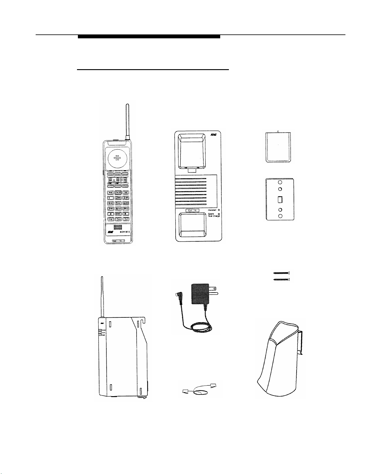
Parts List
Along with this booklet and the Telephone Quick Reference card, the box should contain
the items shown below. If it does not, call for customer support as described on the inside
front cover of this booklet.
Battery Pack
Wall Mounting
Plate
Handset
Radio Module
Battery Charger with
Mounting Base
Charging Cradle 11-foot (3.4 m)
Power Cord/Standard AC
Adapter
8-foot (2.4 m)
Telephone Line Cord
Philips Head
Wood Screws (2)
Handset Carrying
Holster
Introduction
1-3
Page 9
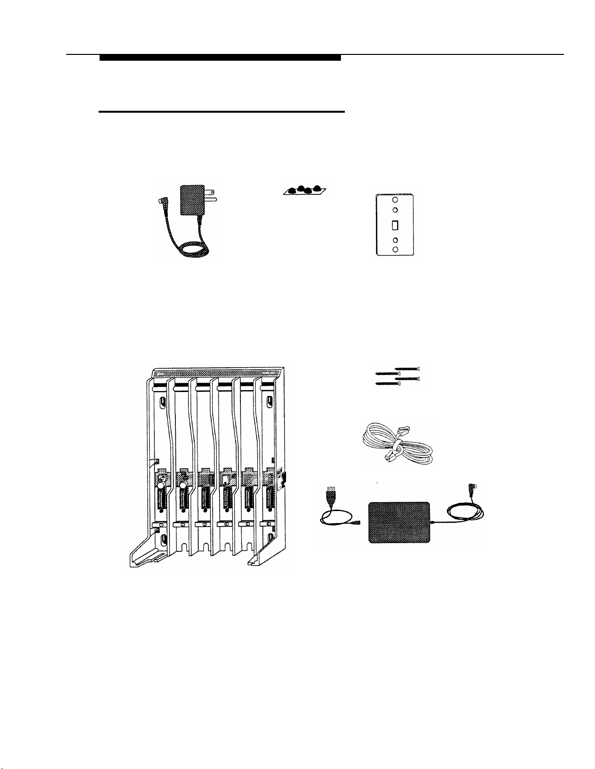
Additional Parts
The following parts may be necessary, depending upon your installation.
Kit of parts (order number D-182866) is required only when a single MDW 9010
phone is installed:
Rubber Feet (4)
Radio Module 11-foot (3.4 m)
Power Cord/AC Adapter
Philips Head
Wood Screws (2)
Wall Mounting
Required when two or more MDW 9010 phones are installed:
Philips Head
Wood Screws (4)
Expansion Cable 6-foot (1.8 m)
for multiple-carrier installation
Plate
1-4
Carrier Assembly 25-foot (7.6 m)
Power Cord and Standard AC Adapter
Carrier
Introduction
Page 10
Installing the MDW 9010
Important Safety Instructions
This booklet contains instructions related to safety labels on the product:
2
WARNING
personal injury if the hazard is not avoided.
CAUTION indicates the presence of a hazard that will or can cause minor
personal injury or property damage if not avoided.
Always follow these basic safety precautions when installing this product to reduce risk of
injury from fire or electric shock.
Make sure the radio module, carrier, and battery charger are unplugged
before you install them.
The exclamation point within an equilateral triangle is intended to alert the
user to the presence of important operating and maintenance (servicing)
instructions in the literature accompanying the product.
WARNING:
Failure to properly ground this product will result in a risk of electrical shock,
which can cause serious personal injury. This product requires a 3-prong AC
power receptacle for safe operation. You should have your receptacle checked
by a qualified electrician before connecting this equipment.
WARNING:
The rechargeable battery pack contains nickel and cadmium. Do not burn or
puncture the battery pack. Like other batteries of this type, if it is burned or
punctured, it could release toxic material which could cause injury. Do not
dispose of it in household garbage. For information about recycling or proper
disposal, consult your local solid waste (garbage) collection or disposal organization.
indicates the presence of a hazard that can cause severe or fatal
Risk of Electric Shock
Installing the MDW 9010
2-1
Page 11

Additional Safety Instructions
for Installation Personnel
■
Install the product to meet all environmental and electrical requirements listed in
Appendix C.
■
All wiring that connects to this equipment and becomes part of the building wiring
must be a minimum of CLASS 2 or U.L. Listed Communications cable.
■
Do not install telephone wiring during a lightning storm.
■
Do not install telephone jacks in a wet location unless the jack is specifically designed
for wet locations. Never touch uninsulated telephone wires or terminals unless the
telephone line has been disconnected at the network interface.
■
Use caution when installing or modifying telephone lines.
■
Install this product securely on a stable surface. Damage may result if the product
falls.
■
Never place this product near or over a radiator or heat register.
■
Slots and openings in the housing and the back or bottom are provided for ventilation.
To protect the housing from overheating, these openings must not be blocked or
covered. Therefore, do not place the product on a bed, sofa, rug, or other similar
surface. Also, do not place this product in an enclosed area unless proper ventilation
is provided.
■
Install this product in a protected location where no one can step on or trip over power
cords and telephone line cords. Do not place objects on the cords that may cause
damage or abrasion.
■
Do not allow anything to rest on the power cord. Do not locate this product where the
cord will be abused by persons walking on it. Do not overload wall outlets as this can
result in the risk of fire or electric shock. Do not staple or otherwise attach the power
cord to building surfaces.
■
Use only the Model # PIDB-270 power supply shipped with this product for the battery
charger or radio module.
■
Use only the Model # SW109 power supply shipped with the carrier.
■
Use only the correct power source. If you are not sure of the power supply to your
location, consult your local power company.
■
This product uses a 3-prong plug in continental U.S. locations. Such plugs are designed for your safety. Do not attempt to defeat this purpose. If your wall outlet will not
accept the plug, the outlet should be replaced by an electrician.
■
Use only the type of battery pack shipped with this product.
2-2
Installing the MDW 9010
Page 12
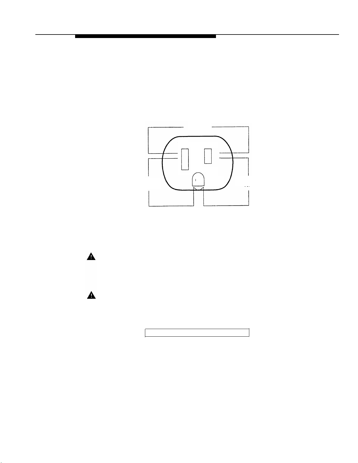
AC Outlet Check
Have a qualified electrician check all of the outlets into which the MDW 9010 radio modules or carriers as well as the communications system switch/control unit will be plugged.
The electrician should check that the hot, neutral, and ground wires are properly connected to the outlet by using a circuit tester.
The outlet can also be tested using a voltmeter by taking the measurements as shown:
120 Volts
G
Phase
120
volts
Neutral
Less than
1 volt
NOTE:
If there is no current to the outlet or the voltages are not correct, the problem should
be corrected by a qualified electrician.
CAUTION:
This equipment is for installation on AT&T PARTNER, PARTNER Plus, PARTNER II,
MERLIN, MERLIN Plus, MERLIN II, MERLIN LEGEND, System 25, System 75, System
85, and DEFINITY communications systems only.
WARNING:
Installation of this equipment for In-Range Out of Building (IROB) conditions
requires the use of protectors. See the documentation that came with your
communications system for more information.
Go to “Radio Modules and Carriers.”
Installing the MDW 9010
2-3
Page 13

Radio Modules and Carriers
This section explains how to install radio modules and carriers. You should proceed
through this section in the following order:
1. “Key Components”
2.
“Positioning a Single Radio Module or Carrier(s)”
3.
Choose one of the following paths, depending upon which components you are
installing:
■
If you are installing a single radio module, go to
“Installing a Single Radio Module.”
■
If you are installing a single carrier, go to
a.
“Setting the Power Level.” Then go to either
b.
“Installing a Single Carrier on a Shelf or Desk” or
“Installing a Single Carrier on a Wall.”
■
If you are installing multiple carriers, go to all of the following:
a.
“Setting the Power Level” then
b.
“Setting the Control/Expansion DIP Switch” then
c.
“Installing Multiple Carriers.”
“Installation Self-Test”
4.
NOTE:
The illustrations in this chapter depict PARTNER system hardware; your hardware may
differ from these illustrations.
2-4
Installing the MDW 9010
Page 14
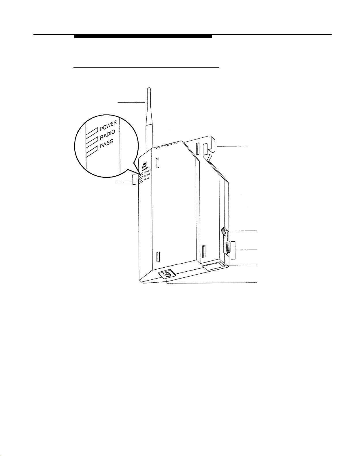
Key Components
Each radio module communicates with a corresponding handset.
Antenna
LEDs
Mounting
Hook
Power Cord
Connector
Card Edge
(Cover not
shown)
Snap Lock
Telephone
Line Cord
Connector
Installing the MDW 9010
2-5
Page 15
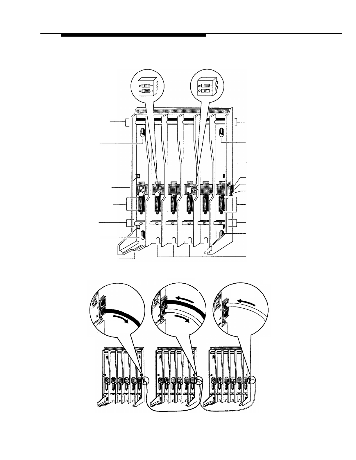
A carrier is required when installing two or more MDW 9010 telephones.
Radio
Module
Mounting
Rods
Wall Mount
Hole
Power Cord
Connector
(hidden)
Card Edge
Connectors
Slot
Numbers
Wall Mount
Hole
Power DIP Control/Expansion
Switch
DIP Switch
Radio
Module
Mounting
Rods
Wall Mount
Hole
In Jack
Out Jack
Out of Sync LED
Card Edge
Connectors
Slot
Numbers
Wall Mount
Hole
Cable
Manager Slot
Rear
Exit Slots
Using the expansion cable provided with each carrier, you may link up to three carriers.
From
Expansion
Carrier #1
To
Expansion
Carrier #1
Control
Carrier
From
Control Carrier
To
Expansion
Carrier #2
Expansion
Carrier #1
Expansion
Carrier #2
2-6
Installing the MDW 9010
Page 16
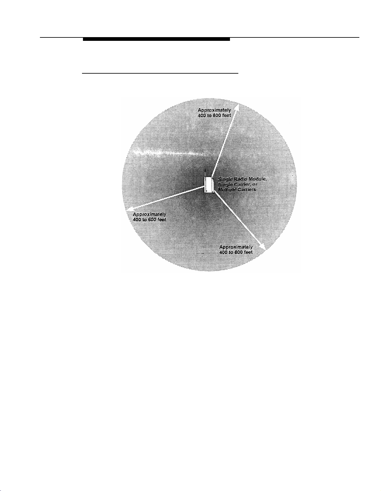
Positioning a Single Radio Module or Carrier(s)
All of your MDW 9010 handsets and their corresponding radio modules operate within a
single zone of coverage:
The range depends on your particular operating environment. For indoor use, intervening
walls will reduce the phone’s range. Try to stay away from concentrations of structural
metal, such as steel and aluminum, and reinforced concrete.
IMPORTANT:
The MDW 9010 phone has a built-in testing feature that you can use before
installation to help determine proper placement of the radio module. To perform
the test, all you need is an electrical outlet for the radio module and a charged
battery pack in the handset (you do not need a communications system switch/
control unit). Refer to “Wireless Test Mode” later in this chapter for details.
General Positioning Rules
Before you install the radio module or carrier(s), note the following rules regarding location
and use. Failure to follow these rules will result in poor performance of your MDW
9010 phone system.
■
Position the radio module or carrier(s) in a central location, relative to the handset(s)
usage area. For convenience, you may want to place the radio module or carrier(s) in
the same room, and on the same wall, as your communications system switch/control
unit. If your switch/control unit is located in a remote location, you may have to run a
telephone line cord from your switch/control unit to the centrally positioned radio module
or carrier(s). The maximum distance is 1,000 feet (333 m) of 26-gauge cable.
Installing the MDW 9010
2-7
Page 17

■
At least
6 feet (2 m)
is required between the radio module or carrier(s) and the communi-
cations system switch/control unit.
■
The radio module or carrier(s) should be placed high on the wall for optimum voice
quality and range. Allow at least 6 inches (15.2 cm) of space between the top of the
antenna on the radio modules and the ceiling.
■
The radio module or carrier(s) should never be installed above a drop, suspended
level ceiling.
■
The radio module or carrier(s) should not be within 6 feet (2 m) of equipment with
microprocessors such as answering machines, personal computers, and fax
machines; electromagnetic equipment such as electric motors; or electrical main
power feeds, junction boxes, circuit-breaker panels, fuse boxes, or 220-volt
power lines.
■
The radio module or carrier(s) should not share the same power line as equipment with
microprocessors such as answering machines, personal computers, and fax machines;
or electromagnetic equipment such as electric motors.
■
If your communications system uses an uninterruptable power supply, such as a backup
generator, be sure to connect the radio module or carrier(s) to that power supply.
Additional rules for a single radio module only:
■
Installing a single radio module on a shelf or desk is not recommended, because it
greatly reduces the range and quality of the transmission.
■
Install a single radio module within 3 feet (1 m) of either side of, and within 6 to 8 feet
(2 to 2.6 m) above, a properly grounded 3-prong electrical outlet that is not controlled
by an on/off switch.
■
You can install a single radio module in a remote location using a telephone line cord
to connect the radio module to the communications system switch/control unit. IROBs
must be used for out-of-building installations.
Additional rules for installing one or more carriers:
■
Install carrier(s) within 15 feet (5 m) of either side of, and within 6 to 8 feet (2 to 2.6 m)
above, a properly grounded 3-prong electrical outlet that is not controlled by an on/off
switch.
■
Choose a location where handset users will not approach the carrier(s) within a radius
of 6 feet (1.8 m) for 1 or 2 carriers or 10 feet (3.1 m) for 3 carriers.
■
Carrier(s) cannot be exposed outdoors to the elements.
■
When installing multiple carriers:
– Install multiple carriers 1 foot (0.3 m) optimally to 4 feet (1.2 m) apart.
– Install multiple carriers on the same horizontal axis (do not install one carrier
higher or lower than another).
–
Install the control carrier as the leftmost carrier, using only the expansion cables
provided.
– There must always be a radio module in slot 6 of the control carrier.
Go to one of the following sections:
■
If Installing one MDW 9010 phone, go to “Installing a Single Radio
Module.”
■
Otherwise, go to “Setting the Power Level.”
2-8
Installing the MDW 9010
Page 18
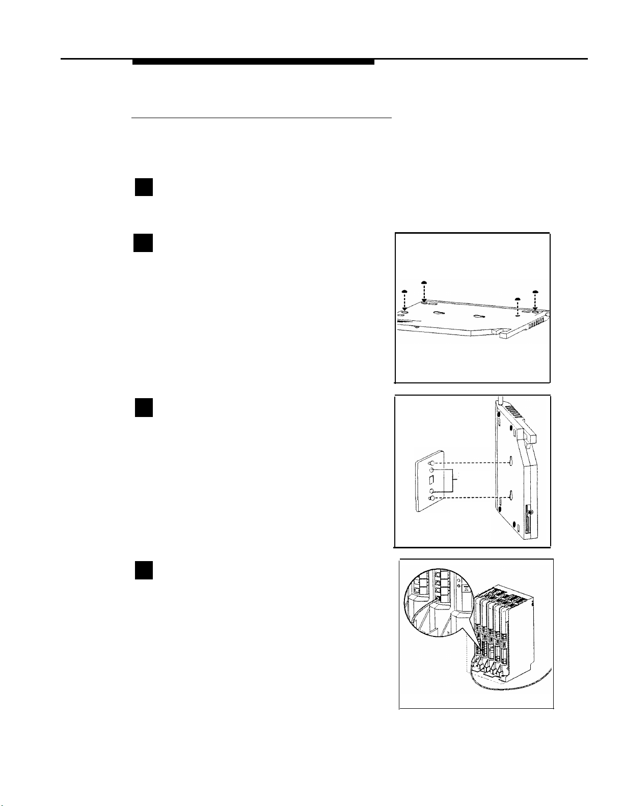
Installing a Single Radio Module
■
Install high on wall, leaving at least 6 inches (15.2 cm) between antenna and ceiling
■
See “Key Components” earlier in this chapter for additional picture detail
Check to make sure the radio module’s power
1
cord is unplugged from the wall outlet before
continuing.
Detach the rubber feet. Apply them to marked
2
areas on the underside of the radio module.
Place the wall mounting plate against the wall.
3
Choose a location backed by a wooden stud (if
unavailable, use toggle bolts instead of the supplied
wood screws). Lightly tap a nail into the wall to start
holes. Then screw the plate flush to the wall. Place
the radio module over the plate, then slide it downward to lock it into place. (Note: Do not remove the
plastic cap covering the radio module’s card edge.)
Screw
Holes
Insert one end of the telephone line cord into
4
an extension jack or terminal/station connector
on your communications system switch/control unit
(refer to your communications system manual for the
proper location).
Installing the MDW 9010
2-9
Page 19
Insert the radio module’s power cord into the
5
side of the radio module. Insert the other end of
the telephone line cord into the bottom of the radio
module.
Plug the power cord/AC adapter into a properly
6
grounded 3-prong wall outlet that is not controlled
by an on/off switch.
CAUTION: Never connect or disconnect
the telephone line cord while the radio
module is plugged into the wall outlet.
Go to “Installation Self-Test.”
2-10
Installing the MDW 9010
Page 20
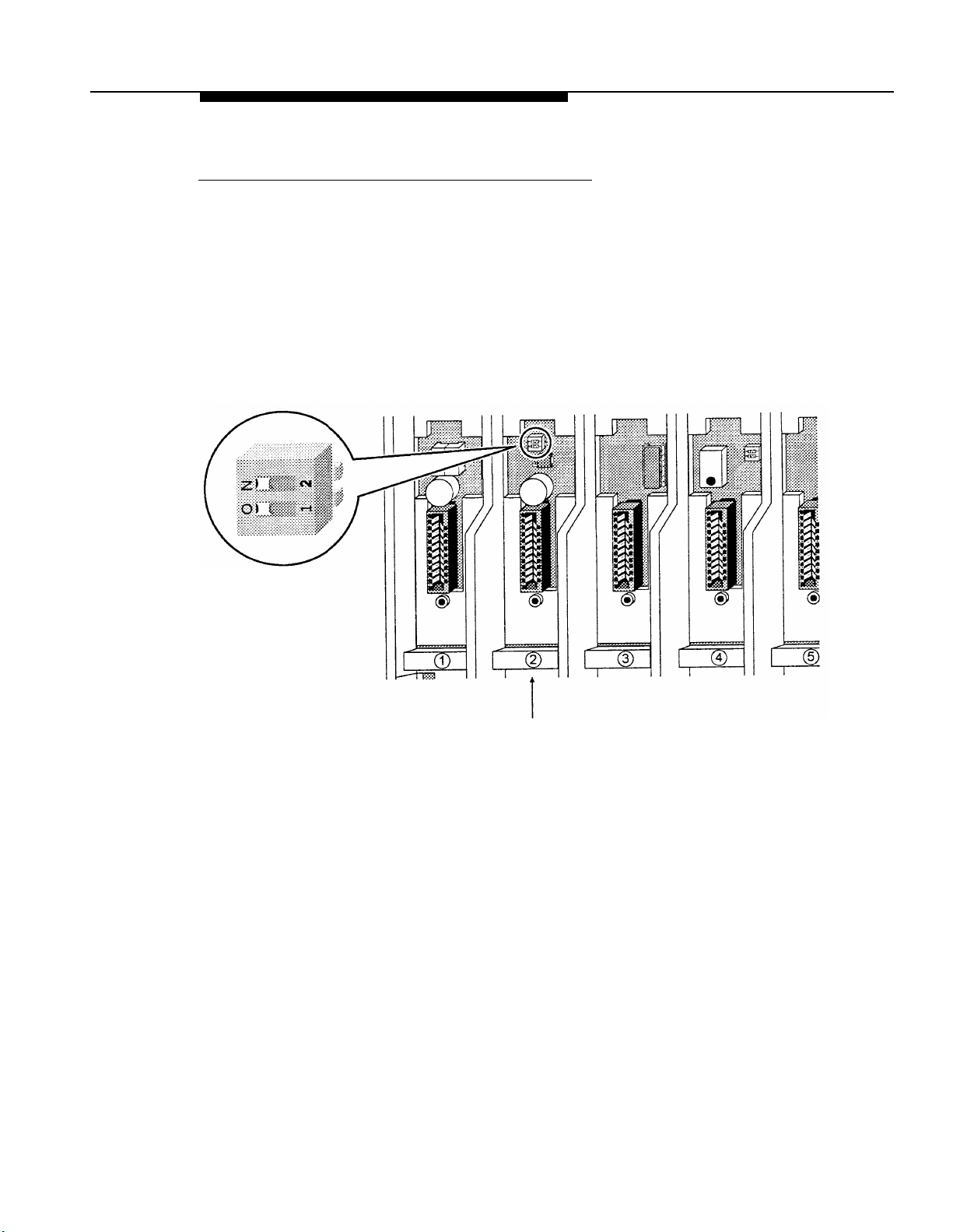
Setting the Power Level
If you are installing one or more carriers in a strip mall, high-rise office building, or similar
environment, the MDW 9010 phones may interfere with other wireless products in use.
■
If this is the case, you may need to adjust the range of the carriers to prevent
overlapping with the other wireless products; follow the instructions in this section.
■
If this is not the case, skip this section and go to “Setting the Control/Expansion DIP
Switch.”
You may adjust the range by setting each carrier’s power DIP switch, located in slot 2:
Power
DIP Switch
Slot 2
Installing the MDW 9010
2-11
Page 21
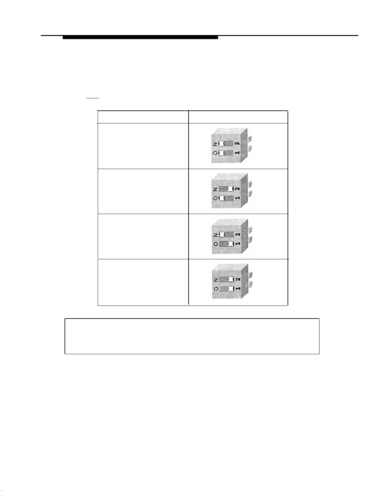
Use a nonmetallic, pointed object to set each carrier’s DIP switch according to the
following table.
IMPORTANT:
You must set the DIP switch for all of the carriers to the same setting.
Desired Range (Approximate)
400 to 600 feet
(122 to 183 m)
300 to 400 feet
(91 to 122 m)
150 to 300 feet
(46 to 91 m)
100 to 150 feet
(31 to 46 m)
Power DIP Switch Settings
2-12
Go to one of the following sections:
■
If installing multiple carriers, go to “Setting the Control/Expansion DIP Switch.”
■
Otherwise, go to “Installing a Single Carrier on a Shelf or Desk” or “Installing a
Single Carrier on a Wall.”
Installing the MDW 9010
Page 22
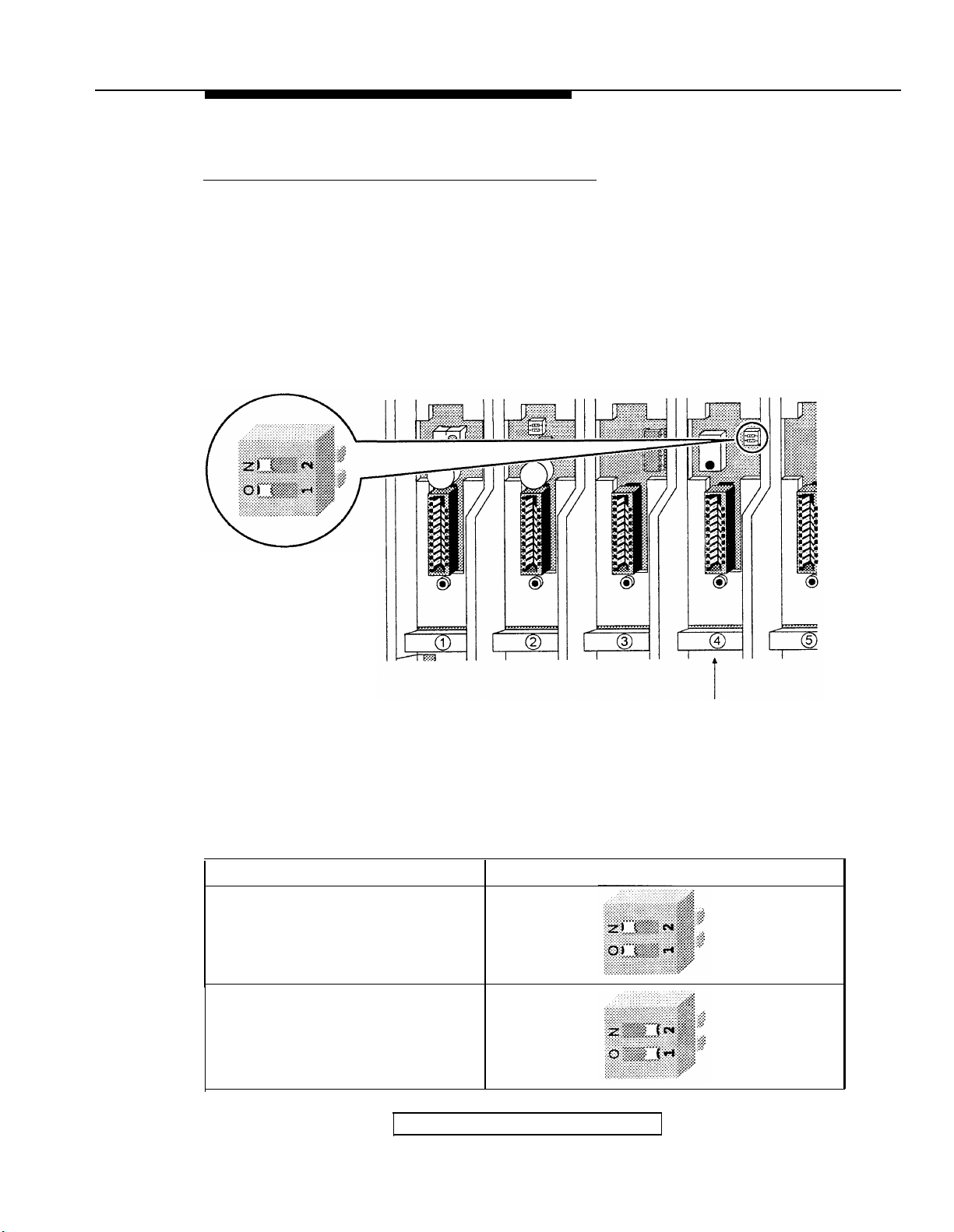
Setting the Control/Expansion DIP Switch
You must follow the instructions in this section if you are installing multiple carriers.
Otherwise, skip to “Installing a Single Carrier on a Shelf or Desk” or “Installing a Single
Carrier on a Wall.”
If you are installing multiple carriers, you must designate one carrier as the control carrier
and the remaining carrier(s) as expansion carriers. The control carrier acts as the “lead”
carrier—its transmit and receive patterns control the expansion carrier(s), ensuring that all
of the linked carriers function as a single system.
You set the control/expansion DIP switch, located in slot 4, to configure the carrier:
Control/Expansion
DIP Switch
Slot 4
Use a nonmetallic, pointed object to set each carrier’s DIP switch according to the following
table.
IMPORTANT:
Only one carrier can be the control carrier; the other carrier(s) must be expansion carriers.
To designate the carrier as a...
control carrier (one carrier only)
expansion carrier (one or two
additional carriers)
Go to “lnstalling Multiple Carriers.”
Use this setting for the DIP switch...
Installing the MDW 9010
2-13
Page 23
Installing a Single Carrier on a Shelf or Desk
■
You will not receive optimum performance if unit is placed on a desk or low shelf
■
Install as high as possible, leaving at least 6 inches (15.2 cm) between antennas
and ceiling if on high shelf
■
Never install or remove a radio module from a carrier that is plugged into a wall
outlet (hot insertion)
■
See “Key Components” earlier in this chapter for additional picture detail
Check to make sure the carrier’s power cord is
1
unplugged from the wall outlet before continuing.
Remove the plastic cap covering each radio
2
module’s card edge before installing the radio
modules in the carrier.
Starting from the leftmost slot (#1), insert each
3
radio module into the carrier by hooking it onto
the radio module mounting rod. Slowly swing the radio
module’s card edge into the card edge connector on
the back of the carrier.
When the card edge is fully seated, a snap lock on
4
the bottom of the radio module will engage.
2-14
Installing the MDW 9010
Page 24
Insert a telephone line cord into the bottom of
5
each radio module.
Slide the telephone line cords through the rear
6
exit slots on the bottom of the carrier. Cords
originating from slots 1 and 6 can share exit slots
with cords from slots 2 and 5 respectively.
Insert the free end of the telephone line cord
7
into the appropriate extension jack or terminal/
station connector on your communications system
switch/control unit (refer to your communications
system manual for the proper location).
Insert the carrier’s power cord into the left side
8
of the carrier.
Installing the MDW 9010
2-15
Page 25
Place the carrier on its feet towards the back of
9
the shelf or desk, making sure it is in a stable
position. Be sure the telephone line cords come out the
rear exit slots in the back of the unit. Arrange the power
cord and telephone line cords beneath the shelf or
desk so no one can step on them or trip over them.
Insert the carrier’s power cord into the AC
10
adapter, then plug the AC adapter into a
properly grounded 3-prong wall outlet that is not
controlled by an on/off switch.
If appropriate, you can wall mount the AC adapter
using its attached wall-mounting bracket.
CAUTION:
Never connect or disconnect telephone line
cords, or insert or remove radio modules,
while the carrier is plugged into the wall
outlet.
Verify that the carrier’s Out of Sync light is not
11
lit. If the light is lit, power down and then
repower the carrier. If the light is still lit, call for help
as described on the inside front cover of this booklet.
Go to “Installation Self-Test.”
2-16
Installing the MDW 9010
Page 26

Installing a Single Carrier on a Wall
■
Install high on wall, leaving at least 6 inches (15.2 cm) between antennas and
ceiling
■
Never install or remove a radio module from a carrier that is plugged into a wall
outlet (hot insertion)
■
See “Key Components” earlier in this chapter for additional picture detail
Check to make sure the carrier’s power cord is
1
unplugged from the wall outlet before continuing.
Place the carrier against the wall. Choose a loca-
2
tion backed by a wooden stud (if unavailable, use
toggle bolts instead- of the supplied wood screws). Hold
the carrier straight; use a level if needed. Using a nail or
pencil, mark screw locations through the four wall mount
holes.
Start the screws, leaving the screw heads approximately ½” (12 mm) from the wall. Place the carrier assembly over the screws, then slide it downward to lock it
into place. Tighten the screws.
Remove the plastic cap covering each radio
3
module’s card edge before inserting the radio
modules into the carrier.
Starting from the leftmost slot (#1), insert each
4
radio module into the carrier by hooking it onto
the radio module mounting rod. Slowly swing the radio
module’s card edge into the card edge connector on
the back of the carrier.
Installing the MDW 9010
2-17
Page 27

When the card edge is fully seated, a snap
5
lock on the bottom of the radio module will
engage.
Insert a telephone line cord into the bottom of
6
each radio module.
Slide the telephone line cords through the cable
7
manager slot on the left front of the carrier.
Insert the free end of the telephone line cord
8
into the appropriate extension jack or terminal/
station connector on your communications system
switch/control unit (refer to your communications
system manual for the proper location).
2-18
Installing the MDW 9010
Page 28

Insert the carrier’s power cord into the left side
9
of the carrier.
Insert the carrier’s power cord into the AC
10
adapter, then plug the AC adapter into a
properly grounded 3-prong wall outlet that is not
controlled by an on/off switch.
If appropriate, you can wall mount the AC adapter
using its attached wall-mounting bracket.
CAUTION:
Never connect or disconnect telephone line
cords, or insert or remove radio modules,
while the carrier is plugged into the wall
outlet.
Verify that the carrier’s Out of Sync light is not
11
lit. If the light is lit, power down and then
repower the carrier. If the light is still lit, call for help
as described on the inside front cover of this booklet.
Go to “Installation Self-Test.”
Installing the MDW 9010
2-19
Page 29

Installing Multiple Carriers
■
Install each carrier high on wall, leaving at least 6 inches (15.2 cm) between
antennas and ceiling
■
Install each carrier 1 foot (0.3 m) optimal to 4 feet (1.2 m) from its
neighboring carrier
■
Never install or remove a radio module from a carrier that is plugged into a wall
outlet (hot insertion)
■
See “Key Components” earlier in this chapter for additional picture detail
Check to make sure the carrier’s power cord is
1
unplugged from the wall outlet before continuing.
Choose a location backed by a wooden stud
2
for the carrier (if unavailable, use toggle bolts
instead of the supplied wood screws).
IMPORTANT:
The leftmost carrier must be the control carrier.
Place the carrier against the wall, leaving enough
room to the right for additional carrier(s) if applicable. Hold the carrier straight; use a level if needed.
Using a nail or pencil, mark screw locations through
the four wall mount holes. Start the screws, leaving
the screw heads approximately ½” (12 mm) from the
wall.
2-20
Repeat steps 1 and 2 for each carrier.
3
Place the carrier over the screws, then slide it
4
downward to lock it into place. Be sure that the
leftmost carrier is the control carrier. Tighten the
screws. Repeat for each carrier.
Connect an expansion cable to the OUT jack of
5
the control carrier.
Installing the MDW 9010
Page 30

Insert the free end of the expansion cable into
6
the IN jack of the expansion carrier immedi-
ately to the right of the control carrier.
NOTE:
Although installing an expansion cable
into the wrong IN or OUT jack will not harm either
carrier, doing so causes all handsets to work
improperly and the Out of Sync LED to light.
If you have a second expansion carrier:
7
Connect an expansion cable to the OUT jack
a.
of expansion carrier #1.
Insert the free end of the expansion cable
b.
into the IN jack of expansion carrier #2.
See “Key Components” earlier in this chapter for an
illustration of a three-carrier setup.
Remove the plastic cap covering each radio
8
module’s card edge before inserting the radio
modules into the carriers.
From
Control
Carrier
Working from left to right, insert a radio module
9
into each slot, starting with slot 1; hook each
radio module onto a mounting rod. Slowly swing the
radio module’s card edge into the card edge connector on the back of the carrier.
IMPORTANT:
There must always be a radio module in slot 6
of the control carrier.
Installing the MDW 9010
2-21
Page 31

When the card edge is fully seated, a snap lock
10
on the bottom of the radio module will engage.
Repeat Steps 9 and 10 for each carrier, until
11
each radio module is inserted into a carrier.
NOTE:
Fill all six slots of the current carrier before inserting radio modules into the next
carrier.
Insert a telephone line cord into the bottom of
12
each radio module.
carrier.
2-22
Slide the telephone line cords through the
13
cable manager slot on the left front of each
Installing the MDW 9010
Page 32

Insert the free end of the telephone line cord
14
into the appropriate extension jack or terminal/
station connector on your communications system
switch/control unit (refer to your communications
system manual for the proper location).
Insert a power cord into the left side of each
15
carrier.
Insert each carrier’s power cord into its AC
16
adapter.
If appropriate, you can wall mount each AC adapter
using its attached wall-mounting bracket.
Installing the MDW 9010
2-23
Page 33

Plug each carrier’s AC adapter into one of the
17
following power sources that is not controlled
by an on/off switch:
■
properly grounded 3-prong wall outlets or
■
a surge suppressor strip.
Power the carriers as follows:
18
If the carriers are plugged into...
one surge suppressor strip
separate wall outlets
Then...
power the strip.
Result:
All carriers will power simultaneously.
power all carriers in this order:
CAUTION:
Never connect or disconnect telephone line
cords, or insert or remove radio modules,
while the carrier is plugged into the wall
outlet.
Verify that the carriers’ Out of Sync lights are
19
not lit. If a light is lit, power down and then
repower the carriers as described in Step 18. If the
light is still lit, call for help as described on the inside
front cover of this booklet.
Control
Carrier
Expansion
Carrier #1
Expansion
Carrier #2
2-24
Go to “Installation Self-Test.”
Installing the MDW 9010
Page 34

Installation Self-Test
Upon installation, the Power and Pass LEDs on each radio module will light. The radio
module(s) then initiate a 2-minute self-test and synchronization. If a radio module’s Pass
LED does not light, repower the module or its carrier. Refer to “Troubleshooting” later in
this booklet if the LED still does not light.
NOTE:
The Radio LED also may light upon installation; however, since the Radio LED has no
significance during the self-test, ignore its operation.
The Radio LED indicates a connection between the handset and the radio module; it
lights when the handset is being used as long as the battery pack in the handset is
charged.
Go to “Battery Charger.”
Installing the MDW 9010
2-25
Page 35

Battery Charger
This section explains how to choose a location for the battery charger and install it. It also
explains how to insert and remove a battery pack.
Positioning the Battery Charger
The battery charger can be placed on a desk, or it can be mounted on a wall. Before you
install the battery charger, note the following considerations:
■
Locate the battery charger within 5 feet (1.6 m) of either side of (and for wall or shelf
mounting, within 5 feet (1.6 m) above) a properly grounded 3-prong electrical outlet
that is not controlled by an on/off switch.
■
If your communications system uses an uninterruptable power supply, such as a
backup generator, be sure to connect the battery charger to that power supply.
■
Do not locate the battery charger where it will be exposed to direct sunlight or water.
WARNING:
The Rechargeable battery contains nickel and cadmium. Do not burn or puncture
the battery. Like other batteries of this type, if it is burned or punctured, it could
release toxic material which could cause injury. Do not dispose of it in household
garbage. For information about recycling or proper disposal, consult your local
solid waste (garbage) collection or disposal organization.
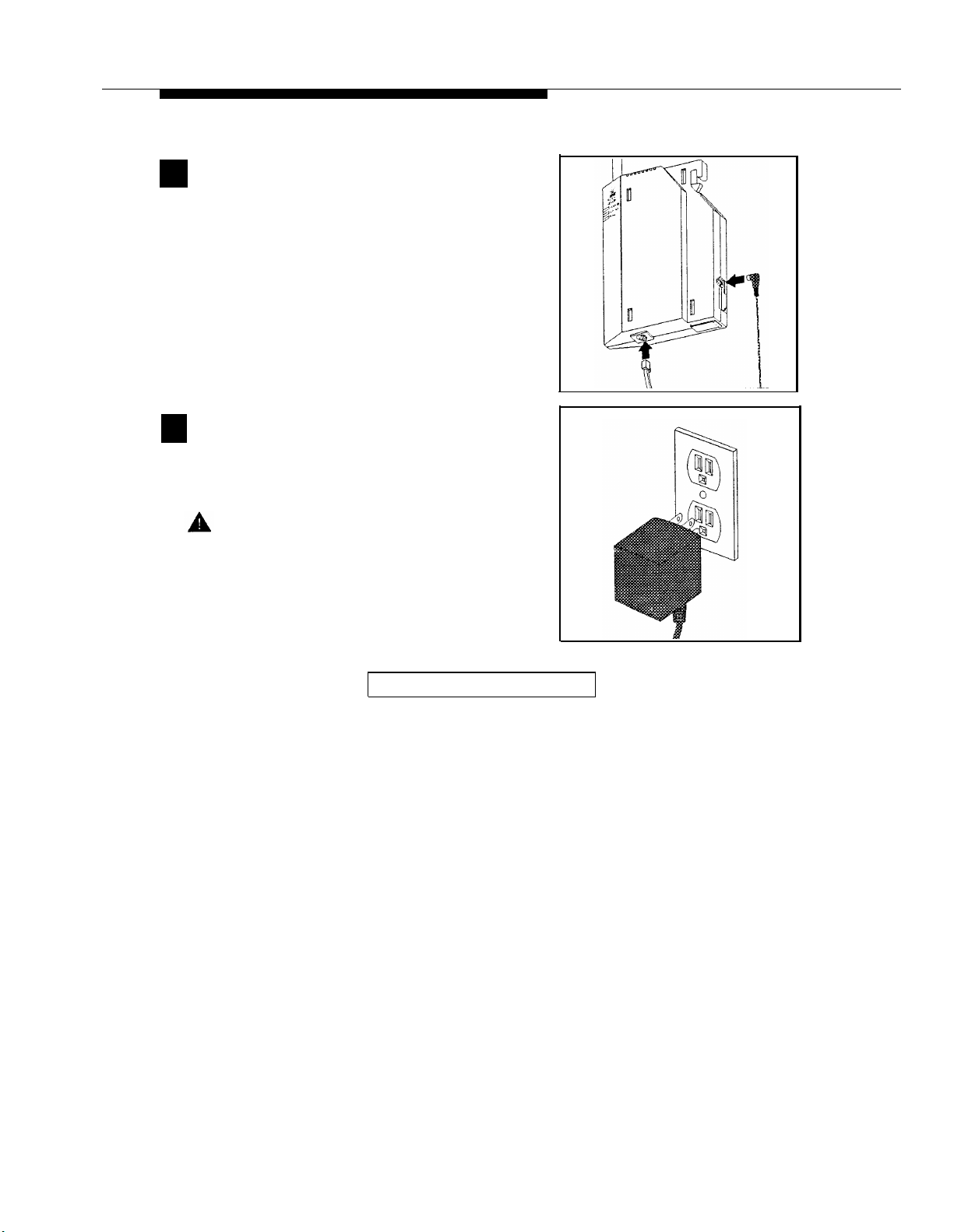
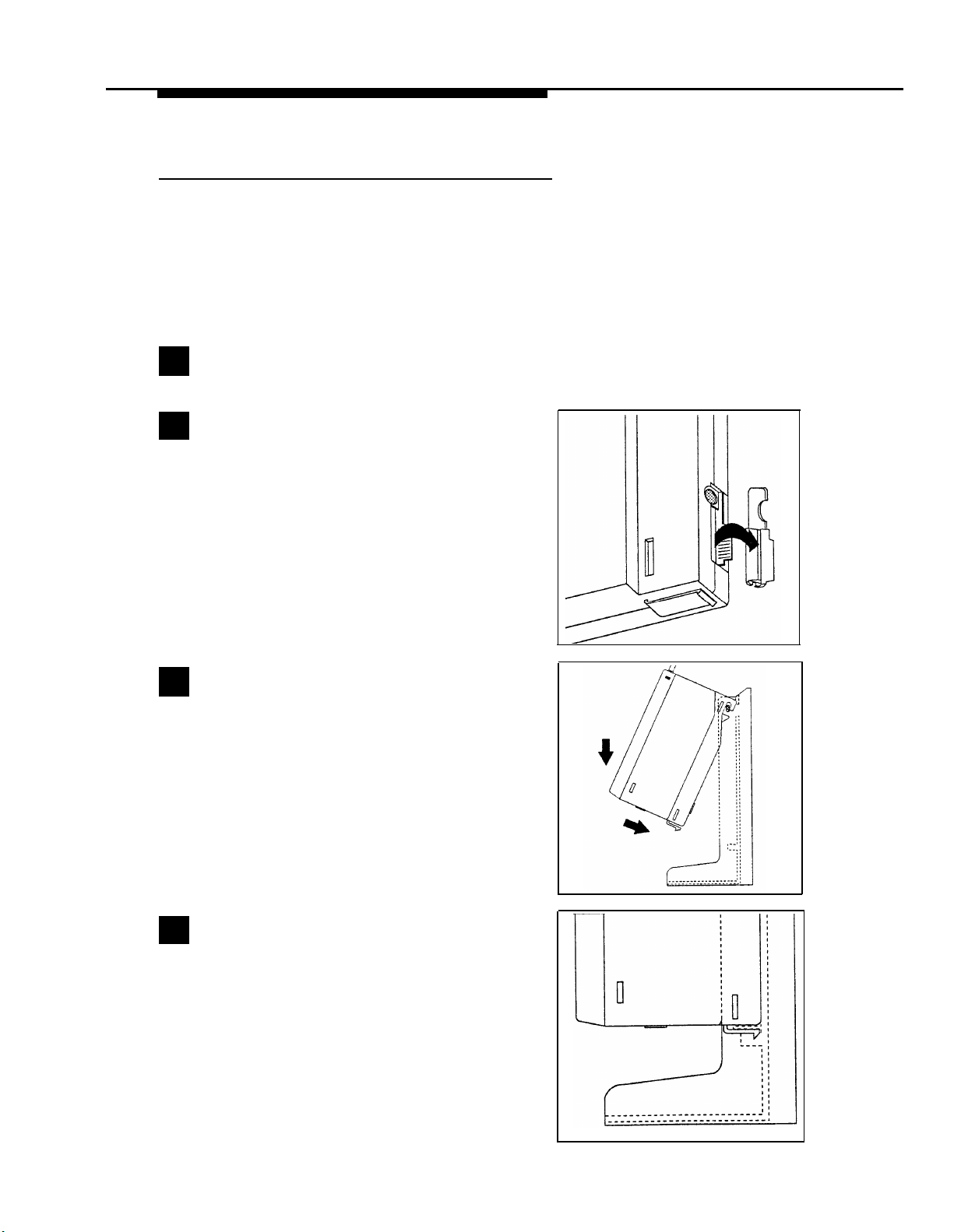
Installing the Battery Charger
■
If you are wall mounting the battery charger, follow Steps 1 through 9
■
If you are desk mounting the battery charger, follow only Steps 1, 4, 5, and 9
Check to make sure the battery charger’s power
1
cord is unplugged from the wall outlet before
continuing. If you are desk mounting, skip to Step 4.
To wall mount, gently place the battery charger
2
upside down. Push in the wide end of the
mounting base (1) and lift upwards (2) to separate the
base from the battery charger.
Wall Mounting Only
2-26
Installing the MDW 9010
Page 36

Reverse the mounting base (so the wide end of
3
the mounting base is above the narrow end of
the battery charger). Insert the tab on the narrow end
of the mounting base into the slot on the wide end of
the battery charger. Insert the tab on the wide end of
the mounting base into the slot on the narrow end of
the battery charger, pushing the mount-ing base
down and slightly inward until the tabs lock into place.
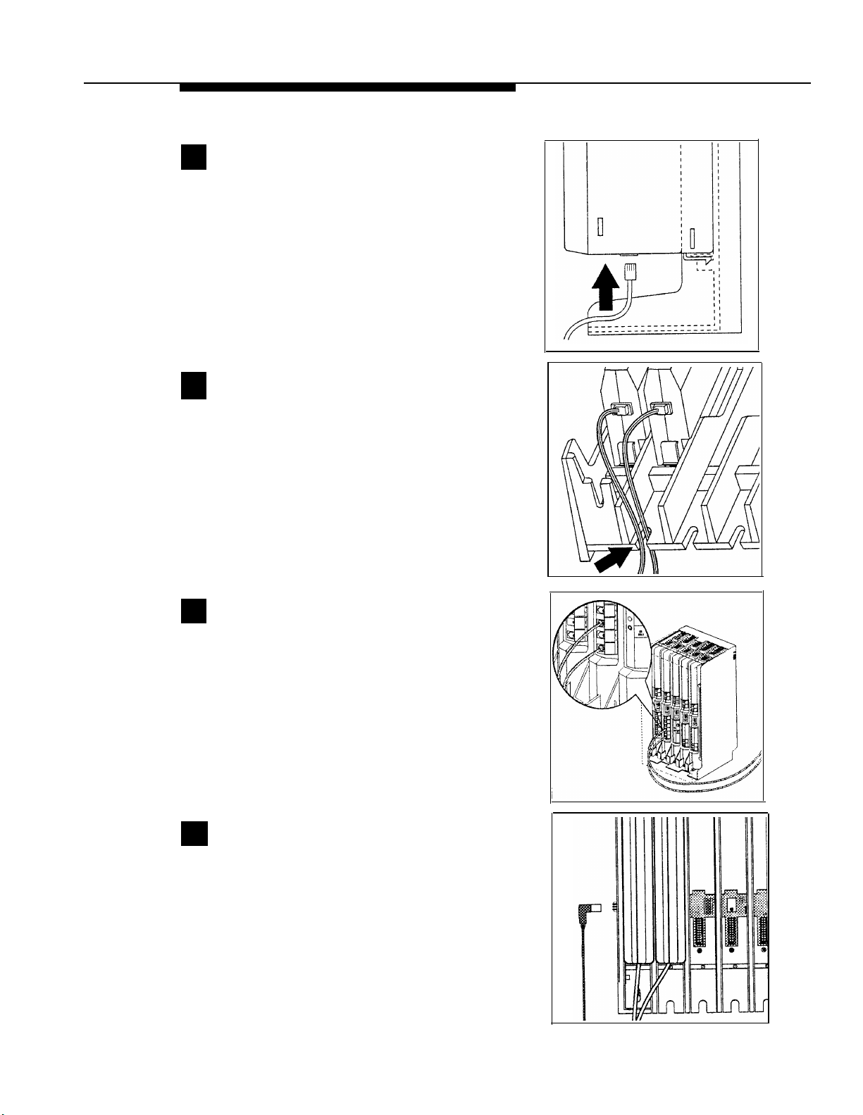
Insert the battery charger’s power cord/AC
4
adapter through the hole in the bottom of the
wide end of the mounting base.
Wall Mounting Only
Insert the power cord/AC adapter into the
5
battery charger plug marked Power. Route the
power cord/AC adapter into the channel marked
Desk or Wall.
If desk mounting, place the battery charger on the
desk, then go to Step 9. If wall mounting, continue
with Step 6.
Reverse the handset hook on the battery
6
charger. Slide the handset hook up out of its
slot. Then turn the hook upside down and replace it
in the slot with the top protruding so the handset can
hang from it.
Wall Mounting Only
Installing the MDW 9010
2-27
Page 37

Place the wall mounting plate against the wall.
7
Choose a location backed by a wooden stud (if
unavailable, use toggle bolts instead of the supplied
wood screws). Lightly tap a nail into the wall to start
the holes.
Wall Mounting Only
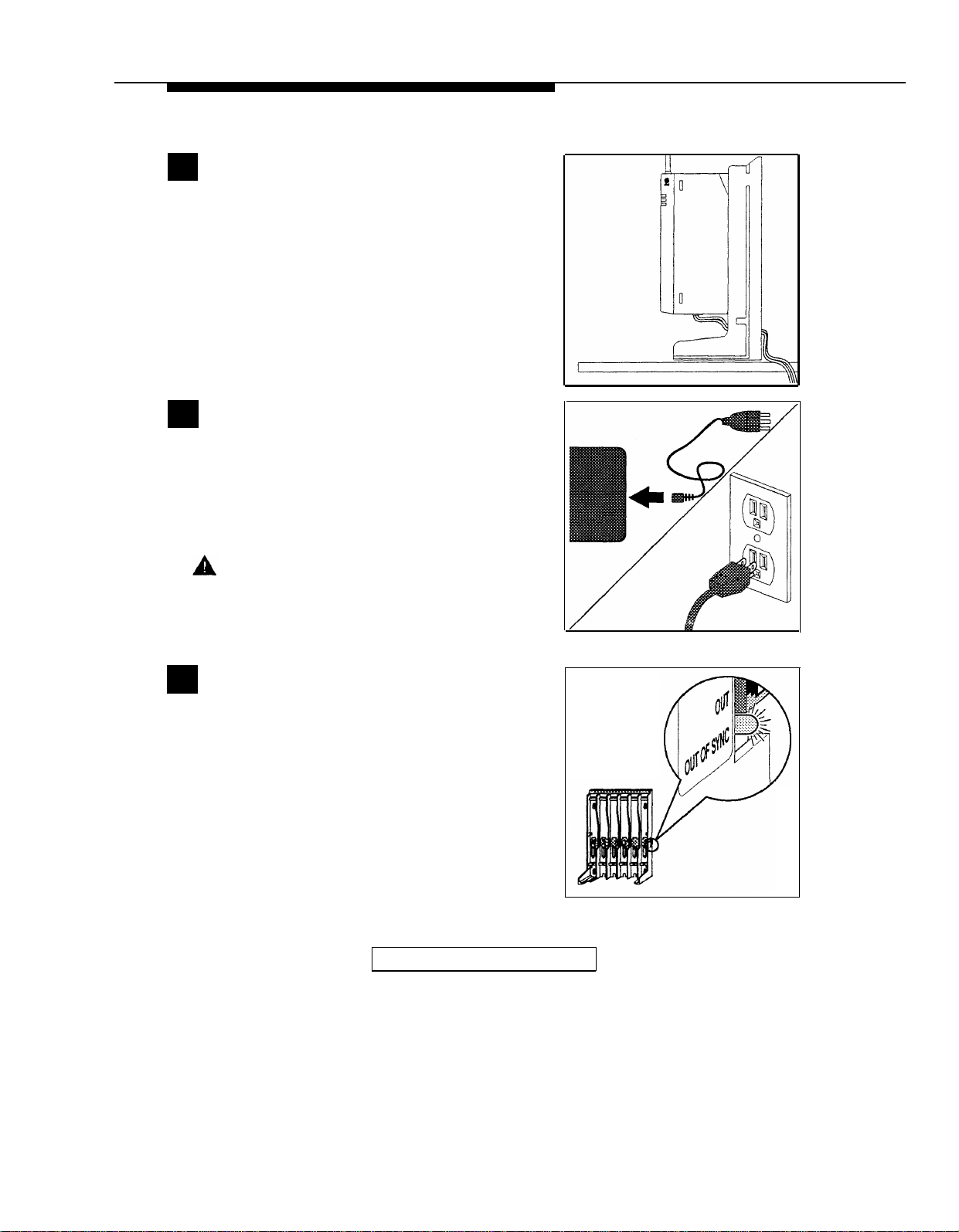
Screw the wall mounting plate flush to the wall.
8
Place the battery charger over the plate, then
slide it downward to lock it into place.
Plug the power cord/AC adapter into a properly
9
grounded 3-prong wall outlet that is not controlled
by an on/off switch.
Wall Mounting Only
Screw
Holes
2-28
Installing the MDW 9010
Page 38

Inserting a Battery Pack Into the Fast Charge Compartment
■
See “The Battery Charger” in Chapter 3 for additional picture detail
Press the finger grip on the side of the cover and
1
lift off the cover.
Insert the tab on the battery pack into the hole on
2
the side of the fast charge compartment. Push
down the battery pack to lock it into place. The Spare
Fast Charge LED should light; if it does not, try
reseating the battery pack.
The Spare Fast Charge LED remains lit until the
battery pack is removed from the compartment.
Replace the cover by inserting it in the cover
3
holes (1). Then swing the cover downward until
it locks into place (2).
The battery pack will be fully charged and ready to
use in 2.5 to 6 hours, depending on its charge state.
(See “Extending Battery Life” in Chapter 3 for more
information.)
Installing the MDW 9010
2-29
Page 39

Removing a Battery Pack From the Fast Charge Compartment
■
See “The Battery Charger” in Chapter 3 for additional picture detail
Press the finger grip on the side of the cover
1
and lift off the cover.
Insert your finger in the finger-hole under the
2
battery pack, then gently pull the battery pack
upward and out.
The Spare Fast Charge LED will go off.
Go to “Handset.”
2-30
Installing the MDW 9010
Page 40

Handset
This section explains how to install the handset battery pack, test the handset, and fill out
labels.
Inserting and Removing the Handset’s Battery Pack
To insert the battery pack, insert the tab in the
1
battery pack into the hole along the top edge of
the battery compartment on the handset.
Battery Tab
Press the battery pack downward to lock it into
2
place.
The battery pack must be charged prior to use. See
“Battery Charger” earlier in this chapter for instructions.
To remove the battery pack, grasp the finger
3
grips on both sides of the battery pack, then
gently pull the battery pack upward and out.
Finger Grip
Installing the MDW 9010
2-31
Page 41

Testing the Handset: Local Test Mode
This test activates the audio warning signal and all visual indicators on the handset
display.
Make sure the handset is turned off.
1.
2.
Press [ # ] for at least 5 seconds.
Local Test Mode
3.
While still holding [
#
], press [
On/Off
].
The handset emits two beeps and all indicators on
the display appear as shown on the right.
If the beeps do not sound or the indicators do not
appear, call for customer support as described on
the inside front cover of this booklet.
4.
Press [
On/Off
] to exit Local Test Mode.
You must exit this mode to initiate proper call
handling.
Wireless Test Mode
You can determine sound clarity, signal strength, and voice quality using Wireless Test Mode.
By performing the tests as you walk around the area in which the handset will be used, you can
determine the handset’s range and the voice quality throughout the area of coverage.
The following procedure provides instructions for all of the Wireless Test Mode tests. You
can perform the tests multiple times and in any order; and you can exit at any time by
pressing [
On/Off
].
NOTE:
Ignore anything that displays if you press [ 4 ] or [ 5 ] while in Wireless Test Mode. These
displays are for AT&T Technicians’ use only.
2-32
1.
To enter Wireless Test Mode:
a.
Make sure the handset is turned off.
b.
Press [ 9 ] for at least 5 seconds.
c.
While still holding [ 9 ], press [
On/Off
].
T (for Test) appears in the handset display. You hear two
beeps, then simulated dial tone.
2.
To determine sound clarity, listen to the simulated dial tone as you walk around.
A clear, steady tone indicates good sound clarity.
Installing the MDW 9010
Page 42

3.
To determine signal strength, press [
1 ].
The display shows a number from 1 to 10. The higher the number, the stronger the
signal, as shown in the table below.
Display Number
10
9
8
7
6
5
4
3
2
1
4.
To determine voice quality, press [ 2 ].
Signal Strength Is
Strong/almost error free
Strong/almost error free
Strong/almost error free
Very good/some errors
Very good/some errors
Good/more errors
Good to Fair/more errors
Fair/more errors
Near end of range
Near end of range/loss of link
The display shows a number between 1 to 10. The higher the number, the better the
voice quality, as shown in the table below. A low number may indicate potential
interfering devices (such as another radio transmitter) in the area.
Display Number
10
9
8
7
6
5
4
3
2
1
Voice Quality Is
Very good
Very good
Errors, but not noticeable in
normal speech
Errors, but not noticeable in
normal speech
Noticeable noise
Noticeable noise
Noisy but intelligible speech
Noisy but intelligible speech
Garbled speech
Unintelligible speech
5.
To
exit
Wireless Test Mode, press [
On/Off
].
Installing the MDW 9010
2-33
Page 43

Filling Out Labels
Remove the protective film from the handset display. Using a ballpoint pen or pencil only,
write the following information on the erasable labels:
(Local Test Mode shown)
Handset Display Labels (6)
On the handset display labels,
write the line numbers or programmed features assigned to
each of the outside line/programmable/intercom/drop buttons.
Handset Battery Charger
Extension Label
On the handset extension label
(below the mouthpiece) and on
the battery charger’s extension
label, write the phone’s extension
number.
Extension Label
For more information, see
Chapter 6, “MDW 9010 Compat-
ibility.”
NOTE:
If you use a pencil or ballpoint pen on these labels, you will be able to erase the
information later. Do not use felt-tip or other types of non-erasable markers. Also, do
not remove the labels.
2-34
Installing the MDW 9010
Page 44

Using the MDW 9010
Important Safety Instructions
This booklet contains instructions related to safety labels on the product:
3
WARNING
personal injury if the hazard is not avoided.
CAUTION indicates the presence of a hazard that will or can cause minor
personal injury or property damage if not avoided.
Always follow these basic safety precautions when using this product to reduce risk of
injury from fire or electric shock.
The exclamation point within an equilateral triangle is intended to alert the
user to the presence of important operating and maintenance (servicing)
instructions in the literature accompanying the product.
WARNING:
Failure to properly ground this product will result in a risk of electrical shock,
which can cause serious personal injury. This product requires a 3-prong AC
power receptacle for safe operation. You should have your receptacle checked
by a qualified electrician before connecting this equipment.
WARNING:
The rechargeable battery contains nickel and cadmium. Do not burn or puncture
the battery. Like other batteries of this type, if it is burned or punctured, it could
release toxic material which could cause injury. Do not dispose of it in household
garbage. For information about recycling or proper disposal, consult your local
solid waste (garbage) collection or disposal organization.
indicates the presence of a hazard that can cause severe or fatal
Risk of Electric Shock
Using the MDW 9010
3-1
Page 45

■
Read and understand all instructions in this booklet before using this product.
■
Observe all warnings and instructions marked on the product.
■
Do not use the product near water or when you are wet. If product comes in contact with
any liquids, unplug the power cord and telephone line cords immediately. Do not plug
the product back in until it has dried thoroughly.
■
Never push objects of any kind into this product through housing slots, since the objects
may touch hazardous voltage points or short out parts that could result in a risk of electric
shock. Never spill liquid of any kind on the telephone.
■
Never place this product near or over a radiator or heat register.
■
Slots and openings in the housing and the back or bottom are provided for ventilation.
To protect the housing from overheating, these openings must not be blocked or covered. Therefore, do not place the product on a bed, sofa, rug, or other similar surface.
Also, do not place this product in an enclosed area unless proper ventilation is provided.
■
Use only the Model # PIDB-270 power supply shipped with this product for the battery
charger or radio module.
■
Use only the Model # SW109 power supply shipped with the carrier.
■
Use only the correct power source. If you are not sure of the power supply to your
location, consult your local power company.
■
This product uses a 3-prong plug in continental U.S. locations. Such plugs are designed
for your safety. Do not attempt to defeat this purpose. If your wall outlet will not accept the
plug, the outlet should be replaced by an electrician.
■
Do not allow anything to rest on the power cord. Do not locate this product where the
cord will be abused by persons walking on it. Do not overload wall outlets as this can
result in the risk of fire or electric shock. Do not staple or otherwise attach the power
cord to building surfaces.
■
Use only the type of battery pack shipped with this product.
■
If you suspect a gas leak, report it immediately, but use a telephone away from the area in
question. The telephone’s electrical contacts could generate a tiny spark. While unlikely, it
is possible that this spark could ignite a heavy concentration of gas. This product is not
approved for use in areas labeled by the Occupational Safety and Health Administration
(OSHA) as “explosive environments.” Only “Explosive Atmosphere Telephones” may be
used in such hazardous environments.
■
Unplug this product from wall outlets and telephone jacks before cleaning. Clean
exposed parts with a soft, damp cloth. Do not use liquid or aerosol cleaners.
3-2
Using the MDW 9010
Page 46

■
Unplug this product from the wall outlet, remove the telephone line cord from the
modular wall jack or communications system switch/control unit, and refer servicing to
qualified service personnel under the following conditions:
When the power cord or plug is damaged or frayed.
–
–
If the product does not operate normally by following the operating instructions.
Adjust only those controls that are covered by the operating instructions because
improper adjustment of other controls may result in damage and will often require
extensive work by a qualified technician to restore the product to normal operation.
–
If the product has been dropped and the housing has been damaged.
■
This product should be serviced by (or taken to) a qualified service center when service
or repair work is required. Do not open the product, there are no user serviceable
components inside.
Using the MDW 9010
3-3
Page 47

The Handset
This section describes the handset’s controls, display, and indicators. It also explains how
to use a carrying holster and a headset.
Handset Controls
Antenna
Headset On/Off Button
Press to turn the headset on. ON
appears in handset display. To
turn off, press again. Turn on to
make or answer a call, and turn off
to “hang up.”
Handset Display
Displays status of lines and range.
For a detailed description, see
“Handset Display” later in this
chapter.
Volume Control
Press +/- to adjust volume of
earpiece or ringer.
Battery Charging
Contacts
Handset battery charges
through these contacts.
Outside Line/Programmable/Intercom/Drop
Buttons (6)
For system button assignments, see Chapter 6,
“MDW 9010 Compatibility.”
Mute
Press to turn the microphone off
for privacy of internal communications.
On/Off
Press to turn the handset on. ON
appears in handset display. To
turn off press again. Turn on to
make or answer a call, and turn off
to “hang up.”
Conf (Conference)
Press to conference in (add)
another party to your call.
Headset Jack
Insert headset cord when using
headset.
Hold
Press to put a call on hold.
Feat (Feature)
Press to enter programming
mode or to use dial-code
features. Not used
on System 25, System 75,
System 85, or DEFINITY
system.
Trans (Transfer)
Press to transfer a call to
another extension.
Extension Label
Write the extension number
on this label using a pencil
or ballpoint pen only.
3-4
Using the MDW 9010
Page 48

Handset Display
18 indicates Local Test Mode; 1 through 10 are used in Wireless Test Mode.
➀
P indicates programming mode.
➁
MUTE indicates handset microphone is turned off after pressing [
➂
T indicates handset is in Wireless Test Mode.
➃
MSG indicates a message has been deposited in your voice mailbox.
➄
Line Status Indicators. See below.
➅
➆
BATT indicates low battery voltage. Handset also emits 2 beeps. For more information, see “Low Battery Indicator” later in this chapter.
RANGE indicates handset is out of range or almost out of range. Handset also
➇
beeps. For more information, see “Handset Range Indicators” later in this chapter.
ON
➈
indicates handset has been turned on after pressing [
On/Off
Mute ].
].
Line Status Indicators
There are six line status indicators; each one corresponds to a specific outside line/
programmable/intercom/drop button. The indicators show either a triangle or a rectangle,
signifying activity as follows:
PARTNER Systems:
A triangle ( ▲ or ▼ ) is the equivalent of a green LED on a wired phone and indicates
activity at YOUR extension.
A rectangle ( ) is the equivalent of a red LED on a wired phone and indicates activity
at ANOTHER extension.
All Other Systems:
A triangle ( ▲ or ▼ ) is the equivalent of a red LED on a wired phone and indicates either
the line you are currently
incoming call.
A rectangle ( )
status of the line, such as whether the line is idle, ringing, or busy.
using or the line you will use once you start to dial or accept an
is the equivalent of a green LED on a wired phone and indicates the
Call Alerter
If a call comes in while the phone is idle, the handset rings. If you are already on a call,
the handset chirps.
Using the MDW 9010
3-5
Page 49

Handset Range Indicators
The handset provides an audible and a visual warning signal to alert you when the handset is not within optimal range of the radio module. Depending on how far away the handset is from the radio module, the signal functions as follows:
■
Out of optimal range. If you walk into an area that is near the end of the optimal
operating range of the radio module, the handset emits two beeps and flashes the
RANGE indicator continuously. At this point, you can continue your conversation or
initiate a call, but you are likely to experience a degradation in voice quality.
■
Loss of communication link. If you walk into an area that is out of operating range of
the radio module, the handset emits five beeps and flashes the RANGE indicator five
times. In this case, you must bring the handset within range of the radio module within
several seconds or the handset will turn off. If the handset turns off, it appears that
your call was disconnected; however it has only been put on Hold. To talk with your
party, move back towards the radio module, press [
for any call placed on Hold.
■
Cannot establish communication link. If you are completely out of range of the radio
module when you attempt to make a call, the handset emits two beeps and flashes the
RANGE indicator two times; then the handset automatically turns off. To make the call,
move back towards the radio module and try again.
Refer to Chapter 5, “Troubleshooting,” for additional information about out-of-range
conditions.
On/Off ], then proceed as you would
3-6
Using the MDW 9010
Page 50

Using the Carrying Holster
The carrying holster allows you to carry the handset with you without having to hold it in
your hand. To attach the holster to your belt, simply thread your belt through the holster’s
belt loop. Then slip the handset into the holster.
Holster Belt
Loop
Handset
Carrying
Holster
To easily remove the handset from the carrying holster, place one hand on the holster to
hold it in place (as shown in the picture above) then pull the handset out with the other
hand.
Using the MDW 9010
3-7
Page 51

Using a Headset
This telephone is equipped with a single-prong headset jack on the bottom of the handset
(near the mouthpiece). A headset assists in call answering, and provides hands-free
operation. AT&T offers a headset designed for use with your wireless phone.
NOTE:
The range of the handset is diminished when you are using a headset. You may need
to move closer to the radio module, or move the radio module closer to you.
To use a headset, simply plug the headset cord into the headset jack on the handset.
CAUTION:
Do not plug any other device into the headset jack.
When using the carrying holster, insert the headset cord into the handset before you
insert the handset into the holster.
3-8
Headset Cord
If desired, the headset cord can be removed from the handset without the call being
dropped. You can then use the handset as you normally would.
NOTE:
Calls cannot be heard on the handset when the headset is connected to the headset jack.
The handset microphone is also deactivated.
Using the Headset On/Off Button
For convenience when using the carrying holster, the headset [
should be used. This button will become active only when the headset cord is plugged into
the headset jack. It is identical in function to the [
On/Off
] button to the left of the [
On/Off
] button near the antenna
Hold
] button.
Using the MDW 9010
Page 52

Answering Calls with a Headset
When you receive a call, you will hear a ringing tone coming from the handset (you will not
hear a tone from the headset itself). To answer the call, press the headset [
near the antenna (or [
On/Off ] to the left of [ Hold ] if the handset is not in the holster ).
On/Off ] button
Placing Calls with a Headset
To place a call with a headset:
1.
Remove the handset from the carrying holster.
2.
Press the [
On/Off ] button near the antenna to access an available line.
3. Dial the number as described in the user instructions that come with your communications system.
4.
Press the [
On/Off ] button to end the call.
Using the MDW 9010
3-9
Page 53

The Battery Charger
This section describes the battery charger and explains how to use battery packs properly.
Handset
Cradle
Battery Contacts
Cover Holes
Battery Tab Hole
Handset LED
Spare Fast
Charge LED
Fast Charge
Compartment
Fingerhole
Handset Cradle
NOTE:
Do not touch, push, or pull any exposed battery contacts.
The charger offers these features:
■
The Fast Charge compartment:
–
Fast charges a battery pack in 2.5 hours
–
Refreshes the battery pack by fully discharging
it before recharging it. This
process reduces or eliminates the potential “memory” effect.
NOTE:
The memory effect, which reduces a battery’s capacity, is caused when you recharge
a battery before it is fully discharged.
■
The Handset Cradle:
–
Slow charges the handset battery pack.
■
The Handset LED, when lit, indicates that the handset battery pack is in charge mode.
(The battery pack is installed in the handset, and the handset is on the battery
charger.)
3-10
Using the MDW 9010
Page 54

■
The Spare Fast Charge LED, when lit, indicates that a battery pack is in the fast
charge compartment:
When the Spare Fast Charge LED... The battery pack inside the fast charge
compartment is...
is steady red
being discharged.
is steady orange being fast charged.
is stead green
fully charged.
flashes orange defective; replace the battery pack.
The battery charger will charge both the handset battery pack and the battery pack in the
fast charge compartment at the same time.
NOTE:
Before you use the MDW 9010 handset for the first time, the battery pack must be
charged.
Low Battery Indicator
When the handset is on and the battery power is low, the handset will emit two beeps and
the BATT indicator in the handset display will flash. When this occurs, you have approximately 1 to 2 minutes of talk time left. At this point, you can either:
■
Complete your call, turn the handset off, and recharge the battery pack, or
■
If you have a charged spare battery pack, place your call on Hold and replace the
handset battery pack with the spare battery pack from the fast charge compartment of
the battery charger. Wait 6 to 10 seconds, then turn the handset on and proceed as you
would for any call placed on Hold.
NOTE:
If you continue talking, the handset will turn off when the battery pack is drained. Your
call will be placed on Hold automatically so you can swap battery packs.
Extending Battery Life
Although a battery pack can be charged in the handset when the handset rests in the battery
charger’s handset cradle, the fast charge compartment’s refresh process is optimized to
give a much faster and more efficient charge to the pack. The fast charge compartment fully
discharges the battery pack before recharging it, thereby ensuring the best possible charge.
The following table shows how long refreshing takes, depending on how much charge is
left in the battery pack when you insert it into the fast charge compartment:
Battery-Pack Charge State
Discharge Time Recharge Time
Low charge (lights BATT 0.5 hours
indicator)
Full charge
4 hours 2 hours
2 hours
Using the MDW 9010
Total Time
2.5 hours
6 hours
3-11
Page 55

IMPORTANT:
Depending on the level of memory effect that the battery has, it is sometimes
necessary to refresh the battery pack in the fast charge compartment twice.
(Insert the battery pack in the fast charge compartment and leave it there until the
Spare Fast Charge LED is steady green. Remove the battery pack from the fast
charge compartment, then reinsert it and leave it until the Spare Fast Charge LED
is steady green a second time.)
Note that your handset will consume power during both talk time (when the handset is on)
and standby time (when the handset is turned off, but out of the battery charger). A fully
charged battery pack provides about 4.5 hours of talk time or about 30 hours of standby
time. As a guideline, you can expect a 1 hour reduction in talk time for every 7 hours of
standby time. Similarly, you can expect a 7 hour reduction in standby time for every hour
of talk time.
We highly recommend that you purchase a second battery pack to use as a spare. With
the spare battery pack in the battery charger’s fast charge compartment, you are assured
of having a fresh, usable battery pack while you are using the battery pack in the handset.
The slow charge that the cradle sends to the handset battery helps keep the handset
operational while it is not in use. It is not a substitute for the refreshing and quick
charging capability of the fast charge compartment. With this in mind, use the battery
charger’s fast charge compartment as the primary recharger.
Follow these steps to ensure an uninterrupted supply of power to your MDW 9010 phone:
Action
If you have only one battery pack, place
the pack into the fast charge compartment
at the end of each day.
If you have two battery packs, exchange
the packs between the handset and the
fast charge compartment at least once a
day. Alternate the battery packs between
the handset and the battery charger’s fast
charge compartment, even if the handset
battery never lights the handset’s BATT
indicator.
Reason
The fast charge compartment refreshes
the battery pack, optimizing the battery’s
performance and extending its life.
Because the handset never discharges
the battery pack, be sure to insert the
pack into the battery charger’s fast charge
compartment at least once a day.
The fast charge compartment refreshes
the battery pack, optimizing the battery’s
performance and extending its life.
3-12
Using the MDW 9010
Page 56

Maintaining the MDW 9010
Important Safety Instructions
This booklet contains instructions related to safety labels on the product:
4
WARNING
personal injury if the hazard is not avoided.
CAUTION indicates the presence of a hazard that will or can cause minor
personal injury or property damage if not avoided.
This telephone is designed to provide trouble-free performance without any special
maintenance procedures. To reduce the risk of accidental damage:
■
Keep the telephone in an area free of dust, smoke, and moisture; do not block the air
vents by placing objects on top of the radio module.
■
Do not place the telephone near a heating duct, radiator, or other heat source, and do not
drop or expose it to excessive shock or vibration.
■
Unplug the battery charger, radio module, or carrier if its power cord is damaged, if
liquid is spilled into it, or if its housing becomes cracked or otherwise damaged.
■
To clean your telephone, wipe the outside housing with a soft, dust-free cloth. If absolutely
necessary, you may use a cloth slightly dampened with a mild soap and water solution.
Dry quickly with a soft cloth.
CAUTION:
Your telephone contains sensitive electronic parts. Never submerge it in any kind of
liquid, and never use detergents, alcohols, solvents, abrasive cleaners, or an excessive amount of water when cleaning the housing and faceplate. To do so could result
in irreparable damage.
indicates the presence of a hazard that can cause severe or fatal
Maintaining the MDW 9010
4-1
Page 57

Always follow these basic safety precautions when installing or using this product to
reduce risk of injury from fire or electric shock.
The exclamation point within an equilateral triangle is intended to alert the
user to the presence of important operating and maintenance (servicing)
instructions in the literature accompanying the product.
WARNING:
Risk of Electric Shock
Failure to properly ground this product will result in a risk of electrical shock,
which can cause serious personal injury. This product requires a 3-prong AC
power receptacle for safe operation. You should have your receptacle checked
by a qualified electrician before connecting this equipment.
WARNING:
The rechargeable battery contains nickel and cadmium. Do not burn or puncture
the battery. Like other batteries of this type, if it is burned or punctured, it could
release toxic material which could cause injury. Do not dispose of it in household
garbage. For information about recycling or proper disposal, consult your local
solid waste (garbage) collection or disposal organization.
■
Read and understand all instructions in this booklet before using this product.
■
Observe all warnings and instructions marked on the product.
■
Do not use the product near water or when you are wet. If product comes in contact with
any liquids, unplug the power cord and telephone line cords immediately. Do not plug
the product back in until it has dried thoroughly.
■
Never push objects of any kind into this product through housing slots, since the objects
may touch hazardous voltage points or short out parts that could result in a risk of electric
shock. Never spill liquid of any kind on the telephone.
■
Never place this product near or over a radiator or heat register.
■
Slots and openings in the housing and the back or bottom are provided for ventilation.
To protect the housing from overheating, these openings must not be blocked or covered. Therefore, do not place the product on a bed, sofa, rug, or other similar surface.
Also, do not place this product in an enclosed area unless proper ventilation is provided.
■
Use only the Model # PIDB-270 power supply shipped with this product for the battery
charger or radio module.
■
Use only the Model # SW109 power supply shipped with the carrier.
■
Use only the correct power source. If you are not sure of the power supply to your
location, consult your local power company.
■
This product uses a 3-prong plug in continental U.S. locations. Such plugs are designed
for your safety. Do not attempt to defeat this purpose. If your wall outlet will not accept the
plug, the outlet should be replaced by an electrician.
■
Do not allow anything to rest on the power cord. Do not locate this product where the
cord will be abused by persons walking on it. Do not overload wall outlets as this can
result in the risk of fire or electric shock. Do not staple or otherwise attach the power
cord to building surfaces.
■
Use only the type of battery pack shipped with this product.
4-2
Maintaining the MDW 9010
Page 58

■
If you suspect a gas leak, report it immediately, but use a telephone away from the area in
question. The telephone’s electrical contacts could generate a tiny spark. While unlikely, it
is possible that this spark could ignite a heavy concentration of gas. This product is not
approved for use in areas labeled by the Occupational Safety and Health Administration
(OSHA) as “explosive environments.” Only “Explosive Atmosphere Telephones” may be
used in such hazardous environments.
■
Unplug this product from wall outlets and telephone jacks before cleaning. Clean
exposed parts with a soft, damp cloth. Do not use liquid or aerosol cleaners.
■
Unplug this product from the wall outlet, remove the telephone line cord from the
modular wall jack or communications system switch/control unit, and refer servicing to
qualified service personnel under the following conditions:
–
When the power cord or plug is damaged or frayed.
–
If the product does not operate normally by following the operating instructions.
Adjust only those controls that are covered by the operating instructions because
improper adjustment of other controls may result in damage and will often require
extensive work by a qualified technician to restore the product to normal operation.
–
If the product has been dropped and the housing has been damaged.
■
This product should be serviced by (or taken to) a qualified service center when service
or repair work is required. Do not open the product, there are no user serviceable
components inside.
■
Always unplug the carrier’s power cord/AC adapter from the wall outlet when:
–
Removing a radio module.
–
Moving a radio module to a new slot in the carrier.
–
Installing a new radio module.
–
Connecting or disconnecting telephone line cords.
Maintaining the MDW 9010
4-3
Page 59

Removing a Radio Module From the Carrier
■
See “Key Components” in Chapter 2 for additional picture detail
■
If you have multiple carriers, slot 6 of the control (leftmost) carrier must always
contain a radio module
Unplug the carrier’s power cord/AC adapter
1
from the wall outlet.
Unplug the telephone line cord from the bottom
2
of the radio module.
4-4
Press up and hold the snap lock on the bottom
3
rear of the radio module.
Maintaining the MDW 9010
Page 60

Slowly swing the radio module’s card edge out of
4
the card edge connector on the back of the
carrier, releasing the snap lock when clear. Unhook the
radio module from the radio module mounting rod by
gently lifting upward.
If you removed a radio module from slot 6 of
5
the control (leftmost) carrier, you must insert
another radio module into this slot. Failure to do so
will cause the carriers to go out of synchronization.
Swapping Extensions
If you want to change your phone’s extension number assignment, make sure the radio
module or carrier is unplugged before you unplug the telephone line cord from the
communications system switch/control unit. Power down and then repower the
carrier(s) after all extension changes are made.
Maintaining the MDW 9010
4-5
Page 61

Ordering Replacement & Optional Parts
To order replacement parts or optional equipment in the continental U.S., call the AT&T
Sourcebook Sales, AT&T Catalog Sales, or AT&T National Parts Sales Center toll free.
When ordering, please use the part numbers shown in the table below.
Item
Battery Pack
White 32034A 32034A
Black
Soft Holster (Clip-On)
Handset Carrying Holster
Gray
Black
Handset Carrying Case
(Hard)
Battery Charger
(includes Battery, Power
Cord and AC Adapter)
White
Black
Power Cord and AC
Adapter for Battery
Charger (11 foot (3.4 m))
AT&T AT&T
Sourcebook
Sales
1 800 451-2100 1 800 635-8866 1 800 222-PART
32036A
32041A 32041A
NA
NA
11135X 11135X
32040A-10
32040A-9 32040A-9
NA
Catalog
Sales Sales Center
32036A
NA 846628527
NA 846501401
32040A-10
NA 847523404
AT&T National
Parts
107546400
107546392
107679409
NA
107581506
107581498
4-6
Carrier
Power Cord and AC
Adapter for Carrier
(25 foot (7.6 m))
Expansion Cable for
Multiple-Carrier
Installation (6 foot (1.8 m))
Telephone Line Cord
(8 foot (2.4 m))
Power Cord and AC
Adapter for Radio Module
(11 foot (3.4 m))
®
Supra
Kit of Parts (For Single
MDW 9010 Installation)
Outside the continental U.S., contact your AT&T Representative or local Authorized Dealer.
900 Headset
3204-CR2A 3204-CR2A
NA
NA
NA
NA
3122-041A 3122-041A
D-182866
NA
NA
NA
NA
D-182866
107503906
847224227
847667870
103786794
847523404
407156892
107586828
Maintaining the MDW 9010
Page 62

Troubleshooting
5
Procedures
If you have a problem with your wireless phone, you may be able to solve it by following
the procedures listed here. If you cannot resolve the problem, call for help as described
on the inside front cover of this booklet.
Installation Problems
Symptom
After plugging the
radio module or
carrier into an
electrical outlet, one
or more radio
module POWER
LEDs do not light.
After plugging the
radio module or
carrier into an
electrical outlet, a
radio module’s
PASS LED does not
light.
Possible Causes
Radio module or carrier(s)
are plugged into an electrical
outlet controlled by a switch.
Power cord of radio module
or carrier(s) is not inserted
properly.
Power cord of radio module
or carrier(s) is defective.
Radio modules are not
synchronized properly.
Radio module or carrier is
inoperable.
Possible Solutions
Plug the radio module or
carrier(s) into an outlet not
controlled by a switch.
Unplug the AC adapter from
the electrical outlet. Disconnect and then carefully reinsert
the power cord into the radio
module or carrier(s). Plug the
AC adapter back into the
electrical outlet.
Call for help.*
1.
Power down, then repower
the control carrier.
2.
Power down, then repower the
expansion carrier(s).
3.
If the problem persists, call
for help.*
Call for help.*
* See “Customer Support” on the inside front cover of this booklet.
Troubleshooting
5-1
Page 63

Installation Problems (continued)
Symptom
One or more Out
of Sync lights are
lit, radio module
PASS LEDs are
not lit, or both.
Handset Problems
Symptom
After placing the
handset in the
battery charger’s
handset cradle, the
handset does not
turn off.
Possible Causes
Expansion cable(s) are
installed in the wrong IN or
OUT jacks, or are not fully
inserted into the correct
jacks.
The carriers were not
powered in the correct order.
A telephone line cord was
disconnected and reconnected without powering
down and repowering the
carrier(s).
Possible Causes
Battery charger is plugged
into an electrical outlet
controlled by a switch.
Battery charger’s power cord
is not inserted properly or is
not inserted at all.
Possible Solutions
1.
Verify that all expansion cables
are installed in the correct IN
and OUT jacks.
2.
Ensure that all expansion
cables are fully inserted into
their jacks.
3.
Power down, then repower the
control carrier.
4.
Power down, then repower the
expansion carrier(s).
Possible Solutions
Plug the battery charger into
an outlet not controlled by a
switch.
Unplug the AC adapter from
the electrical outlet. Disconnect and then carefully reinsert
the power cord into the battery
charger. Plug the AC adapter
back into the electrical outlet.
5-2
After pressing
[
On/Off
], dial tone is
not heard and
handset display
does not show
anything.
Handset does not
respond to repeated [
On/Off
] button
presses.
Troubleshooting
Battery pack is not charged
sufficiently.
Telephone line cord is not
plugged into the radio
module.
There was a recent occurrence of lightning, or a
power failure.
Remove the handset battery
pack, place it in the battery
charger’s fast charge compartment until fully charged. If you
have a charged battery pack,
place it in the handset while the
other battery pack recharges.
Power down the radio module or
carrier(s). Plug the telephone line
cord into the radio module, then
repower the radio module or
carrier(s).
■
Remove the battery pack from
the handset for 10 seconds,
then replace it.
■
Check to see if the radio
module or carrier is receiving
power.
Page 64

Handset Problems (continued)
Symptom
After pressing
[
On/Off
], dial tone is
not heard and the
RADIO
LED on
the radio module
does not light.
You can hear the
party on the other
end, but they
cannot hear you.
MUTE
appears in
the handset display.
Possible Causes
There is no battery
pack in the handset.
Battery pack is not
inserted properly in the
handset.
Battery pack is not
charged sufficiently.
Handset is out of range
of its matching radio
module.
There is interference
from another electrical
device (microwave) or
metal walls.
The [
Mute
] button was
pressed inadvertently.
Possible Solutions
Insert a battery pack in the handset.
Make sure the battery pack is inserted
properly in the handset.
Remove the handset battery pack,
place it in the battery charger’s fast
charge compartment until fully
charged. If you have a charged battery
pack, place it in the handset while the
other battery pack recharges.
Move the handset closer to the radio
module.
Remove the electrical device that is
causing interference, or move the
handset to another location.
Press [
Mute
] again to turn off the mute
feature.
After pressing [
On/Off
],
the handset beeps
and
RANGE
shows
in the handset
display.
No ring on incoming call,
RANGE
appears in handset
display.
While talking and
walking, the
handset beeps and
RANGE
flashes in
the handset display.
Handset is out of range
of its matching radio
module.
An electrical device is
interfering with your
communications link.
Handset is out of range of
its matching radio
module.
You are approaching an
out-of-range condition.
Move the handset closer to the radio
module.
Remove the interfering device or power
it off, or move the handset to another
location.
Move the handset closer to the radio
module.
Move back towards the handset’s matching radio module until the display stops
showing
RANGE.
Troubleshooting
5-3
Page 65

Handset Problems (continued)
Symptom
While talking and waking,
the handset beeps and
RANGE
flashes in the
handset display. You keep
walking away from the
handset’s matching radio
module, the display goes
blank, and your call
appears to be disconnected.
After placing a call on
Hold, you walk away from
the handset’s matching
radio module. Your
handset beeps, the
handset display flashes
RANGE,
and your call
appears to be disconnected.
Handset display beeps
and shows
RANGE
in
an area where the
handset used to work
well.
Possible Causes
You are out of range of the
radio module.
YOUR
CALL HAS NOT BEEN
DISCONNECTED. IT
Possible Solutions
Move back towards the radio
module. Press [
On/Off
], then proceed
as you would for any call placed on
Hold.
HAS BEEN PLACED ON
HOLD.
You are out of range of the
radio module.
YOUR
CALL HAS NOT BEEN
DISCONNECTED. IT IS
Move back towards the radio
module. Press [
On/Off
], then proceed
as you would for any call placed on
Hold.
STILL ON HOLD.
A power loss has thrown Check the carriers’ Out of Sync
the carriers out of
synchronization.
lights. If any are lit, repower the
carriers in order, from left to right.
Range for calls is lower
than expected.
Battery Problems
Sympton
BATT appears in the
handset display.
There are environmental
limitations.
Possible Causes
Battery power is low.
Reinstall the radio module or
carrier as high as possible on the
wall and away from electrical
equipment. See “General Positioning Rules” in Chapter 2 for
more information.
Possible Solutions
You have 1 to 2 minutes of talk
time left. Either:
■
Complete your call, turn the
handset off, and recharge the
battery pack in the battery
charger’s fast charge compart-
ment.
■
If you have a fully charged spare
battery pack, place your call on
Hold. Swap the battery packs.
Wait 6 to 10 seconds, then turn
the handset on and proceed as
you would for any call placed on
Hold.
5-4
Troubleshooting
Page 66

Battery Problems (continued)
Symptom
The handset battery
pack does not last as
long as it used to under
similar conditions.
You get less than 4.5
hours of talk time when
you use a battery pack
that was charged in the
fast charge compartment.
Fast Charger Problems
Symptom
Handset
charger does not light
when handset is placed
in battery charger.
Spare Fast Charge
on battery charger does
not light when the battery
pack is placed in battery
charger’s fast charge
compartment.
Spare Fast Charge
flashes orange.
LED on battery
LED
LED
Possible Causes
The battery pack needs to
be refreshed.
The battery pack needs to
be refreshed a second
time.
Possible Causes
Handset is not seated
properly in battery charger.
Battery charger is plugged
into an electrical outlet
controlled by a switch.
The handset battery pack
is defective or dead.
The battery pack is not
seated properly in battery
charger’s fast charge
compartment.
The battery pack is defective or dead.
The battery pack is defective
or dead.
Possible Solutions
When
BATT
flashes, insert the
handset battery pack into the
fast charge compartment until
the Spare Fast Charge LED is
steady green (2.5 to 6 hours).
Reinsert the battery pack into
the fast charge compartment
until the Spare Fast Charge
LED is steady green again.
Possible Solutions
Make sure the handset is
seated properly in the battery
charger. Also check that there
are no obstructions on the
handset or battery charger
contacts. Try cleaning the
contacts with a soft eraser.
Plug the battery charger into
an outlet not controlled by a
switch.
If you have a fully charged
spare battery pack, use it to
replace the battery pack in
the handset. Place the handset battery pack in the battery
charger’s fast charge compartment.
Make sure the battery pack is
seated properly in the battery
charger’s fast charge compartment. Also check that there are
no obstructions on the battery
pack or battery charger
contacts. Try cleaning the
contacts with a soft eraser. Wait
one minute. If the LED still
doesn’t light, order a new
battery pack.
Wait one minute. If the LED
still doesn’t light, order a new
battery pack.
Order a new battery pack.
Troubleshooting
5-5
Page 67

Voice Quality Problems
Symptom
Handset range
and voice quality
are not as good
as they were
before.
Voice quality in a Handset is too close Move the handset at least 6 feet (1.8 m)
specific location
is poor and noisy.
Volume is too low Handset or radio Place the handset in Wireless Test Mode
at any setting and
there is noise on
the line. clear and strong, the handset and radio
Possible Causes
A competing radio
device has been as described in Chapter 2. If the signal
installed in the area.
Carriers are out of
synchronization.
to the carrier(s).
module is not working
properly.
The connection
between the radio module or carrier and the switch/control
module or carrier and
the switch/control unit
is not proper.
Possible Solutions
Place the handset in Wireless Test Mode
strength and voice quality readings are
low, look for a newly installed radio
device nearby. Remove it or move your
handset’s matching radio module.
1.
Verify that all expansion cables are
installed in the correct IN and OUT
jacks.
2.
Ensure that all expansion cables are
fully inserted into their jacks.
3.
Power down, then repower the control
carrier.
4.
Power down, then repower the expansion carrier(s).
away for a one- or two-carrier setup, or
10 feet (3.1 m) away for a three-carrier
setup.
and determine sound clarity as described in Chapter 2. If the dial tone is
module are OK.
Check the connection between the radio
unit.
5-6
Troubleshooting
Telephone line may be
producing noise.
Your business
has two or more occurrence of lightwireless phones ning, or a power plug the AC adapter back into the outlet.
installed and all
handsets seem to
have developed
interference
problems at the
same time.
There was a recent
failure.
Report line trouble to your local phone
company.
Unplug the carrier’s AC adapter from the
electrical outlet. Wait 10 seconds, then
Page 68

Voice Quality Problems (continued)
Symptom
You are on a call
and you hear radio
interference when
another call rings.
Voice quality for a
call in progress
degrades for more
than 6 seconds
(PARTNER, PARTNER Plus, PARTNER II in key
mode, MERLIN,
MERLIN Plus, and
MERLIN II phone
systems only).
Possible Causes
System in key mode
has all lines set to
ring. An incoming
call “wakes up” all of
the other radio
modules at the same
time to ring the other
phones.
Line ringing options
are incorrectly set for
extensions with radio
modules in the first
expansion carrier.
Possible Solutions
Refer to Chapter 6, “MDW 9010 Compatibility,” to reset line ringing options.
Refer to Chapter 6, “MDW 9010 Compatibility,” to reset line ringing options.
Troubleshooting
5-7
Page 69

MDW 9010 Compatibility
6
Programming and Call Handling Instructions
After you have installed your MDW 9010 phone and understand the controls and displays,
use the programming and call handling instructions that come with your communications
system; follow the user instructions for the phone type identified below:
For this communications system...
PARTNER®
MERLIN®, MERLIN Plus, and MERLIN II
MERLIN LEGEND®
System 25
System 75, System 85, and DEFINITY®*
NOTE:
The MDW 9010 phone is fully compatible with the PARTNER family of communication
systems. For the remaining communications systems, however, you must carefully
note the functional differences between your wireless phone and the phone type
identified in the table, as described on the following pages.
Use the instructions for a...
MDW 9000 phone.
5-button phone.
10-button ATL set.
10-button ATL set.
7303s set.
Entering Station Programming Mode
On all PARTNER, MERLIN, and MERLIN LEGEND systems:
■
To enter programming mode, turn on the handset, press [ Intercom ], then press [ Feat ]
followed by [ 0 ] [ 0 ].
■
To exit programming mode, press [ Feat ] followed by [ 0 ] [ 0 ] or turn off the handset.
NOTE:
The above instructions do not apply on System 25, System 75, System 85, and
DEFINITY systems, because features are assigned by the system administrator.
* For DEFINITY G3V3 systems, you can administer the system for the MDW 9000 telephone (rather than a
7303s set) and follow the user’s instructions in the MDW 9000 Wireless Telephone User’s Guide, order
number 555-230-768.
MDW 9010 Compatibility
6-1
Page 70

Programming System Features
PARTNER Systems
■
PARTNER II and PARTNER Plus system buttons should be assigned as follows; 1, 2, 3, and
4 are line or feature buttons (for a PARTNER system, buttons 1 through 4 are line only):
18
ON
RANGE
Setting the line ringing options: Use the following guidelines to ensure optimal voice
quality when using MDW 9010 phones with a PARTNER, PARTNER Plus, or PARTNER II
system in key mode:
AT&T Phone
System
PARTNER
PARTNER
PLUS,
PARTNER II
System with Two Carriers
(one control and one expansion
carrier)
1. Set Line Ringing for each
extension that has a radio
module in the control carrier to
Ring.
2.
Set Line Ringing for each
extension that has a radio
module in the expansion
carrier to No Ring. (Install an
external audible alert for these
extensions.)
1.
Set Line Ringing for each
extension that has a radio
module in the control carrier to
Ring.
2.
Set Line Ringing for each
extension that has a radio
module in the expansion
carrier to Delayed Ring.
PMUTE
MSG
BATT
System with Three Carriers
(one control and two expansion
carriers)
Not applicable: PARTNER
supports up to 12 phones.
1.
Set Line Ringing for each
extension that has a radio
module in the control carrier to
Ring.
Set Line Ringing for each
2.
extension that has a radio
module in expansion carrier #1
to Delayed Ring.
3.
Set Line Ringing for each
extension that has a radio
module in expansion carrier #2
to No Ring. (Install an external
audible alert for these
extensions.)
6-2
NOTE:
For PARTNER II hybrid systems that use pooled lines, set the Line Ringing options as
described in the above table if more than six MDW 9010 handsets have the same
pooled line appearance.
MDW 9010 Compatibility
Page 71

MERLIN Systems
■
It is recommended that you use MERLIN 206/410/820 systems installed with Feature
Package 2 with your wireless phone.
■
On MERLIN II and MERLIN LEGEND systems, you must connect your wireless phone
to an available jack on either a 408 outside line/analog telephone module or a 008
analog telephone module.
■
You must disable the Voice Announce feature. This telephone does not have a speaker
function.
■
The wireless phone should not be assigned to a paging group.
■
To program the Ringing Option feature, use the “arrow” and “rectangle” indicators in
the display as the equivalent of red and green LEDs, respectively.
■
For MERLIN II system users, if you program an Auto Intercom button, idle line preference
must be set to intercom.
■
If any of your incoming lines has the call waiting feature, program the Recall feature on one
of the programmable buttons and press it before you pick up a waiting call. You can dial #50
before you pick up a waiting call on the following: MERLIN 206/410/820 systems only with
Feature Package 2, and all MERLIN Plus, MERLIN II, and MERLIN 1030/3070 systems.
Pressing the [
■
MERLIN 206/410/820 and MERLIN Plus system buttons should be assigned as follows;
2, 3, 4, and 5 are line or feature buttons:
On/Off
] button will disconnect the call.
18
ON
RANGE
■
To use MERLIN LEGEND system feature codes with this phone, program the top right-
PMUTE
MSG
BATT
hand button as a System Feature button. This will permit you to use the wide array of
LEGEND system features by turning the set on, pressing the System Feature button,
and dialing the appropriate “ * ” code number. Your wireless phone's [
Feat ] button only
allows you to enter programming mode. It does not work when using MERLIN LEGEND
system features.
■
MERLIN 1030/3070, MERLIN II, and MERLIN LEGEND system buttons should be
assigned as follows; 3, 4, and 5 are line or feature buttons:
18
ON
RANGE
PMUTE
MSG
BATT
MDW 9010 Compatibility
6-3
Page 72

Setting the line ringing options: Use the following guidelines to ensure optimal voice
quality when using MDW 9010 phones with MERLIN, MERLIN Plus, and MERLIN II:
AT&T Phone
System
MERLIN,
MERLIN II,
MERLIN PLUS
System with Two Carriers
(one control and one
expansion carrier)
1.
Set Line Ringing for each
extension that has a radio
module in the control
carrier to Ring.
2.
Set Line Ringing for each
extension that has a radio
module in the expansion
carrier to Delayed Ring.
System with Three Carriers
(one control and two
expansion carriers)
1.
Set Line Ringing for each
extension that has a radio
module in the control
carrier to Ring.
Set Line Ringing for each
2.
extension that has a radio
module in expansion
carrier #1 to Delayed Ring.
Set Line Ringing for each
3.
extension that has a radio
module in expansion
carrier #2 to No Ring.
(Install an external audible
alert for these extensions.)
NOTE:
For MERLIN LEGEND systems that use pooled lines, set the Line Ringing options as
described in the above table if more than six MDW 9010 handsets have the same
pooled line appearance.
6-4
MDW 9010 Compatibility
Page 73

System 25
■
For Releases 1, 2, and 3, this telephone must be administered as a 10-button MERLIN
set (type 303).
■
Either a TN762B Hybrid pack or a ZTN79 ATL pack must be used to connect the
switch and the MDW 9010 telephone.
■
Assigning features may be done only by the system administrator.
■
Use the following features with caution:
Automatic Intercom, Bridging, Coverage, Direct Station Selection, Personal Line,
Pooled Facility, Send All Calls (use with single ring reminder).
Since these features provide visual indication that the feature is turned on, be aware that if
you turn off the handset when using that feature, you may forget that the feature is on.
■
Do not assign the following features: Auto Answer, Scroll, Inspect, Directory, Next, Local,
Call, and Manual Callback Queuing.
■
If programming the Flex DSS or Repertory Dial feature, dial the number to be recorded
and push the button you are assigning to the feature. You will receive 3 short beeps
and a dial tone to confirm programming.
■
If you are programming numbers for the Station Speed Dial feature, dial the numbers to be
stored then dial the Personal Speed Dialing code (#20 through #39), including the #.
Listen for a confirmation tone followed by a dial tone.
■
System 25 buttons should be assigned as follows; 7, 8, 9, 10, and 11 are system
access or feature buttons:
18
ON
RANGE
PMUTE
MSG
BATT
NOTE:
For System 25 systems that use pooled lines, set the Line Ringing options as described
in the following table if more than six MDW 9010 handsets have the same pooled line
appearance.
AT&T Phone
System
System 25
System with Two Carriers
(one control and one
expansion carrier)
1.
Set Line Ringing for each
extension that has a radio
module in the control
carrier to Ring.
2.
Set Line Ringing for each
extension that has a radio
module in the expansion
carrier to Delayed Ring.
System with Three Carriers
(one control and two
expansion carriers)
1.
Set Line Ringing for each
extension that has a radio
module in the control
carrier to Ring.
2. Set Line Ringing for each
extension that has a radio
module in expansion
carrier #1 to Delayed Ring.
3.
Set Line Ringing for each
extension that has a radio
module in expansion
carrier #2 to No Ring.
(Install an external audible
alert for these extensions.)
MDW 9010 Compatibility
6-5
Page 74

System 75, System 85, and DEFINITY Systems
This phone must be administered as a 7303s Hybrid terminal for the following systems:
■
System 75 - R1V1, R1V2, and R1V3
■
System 85 - R2V1, R2V2, R2V3, and R2V4
■
DEFINITY G1 - (R1V4)
■
DEFINITY G2 - G2.1 and G2.2 - (R2V5, R2V6)
■
DEFINITY G3 Version 1 - (R1V5)
■
DEFINITY G3 Version 1.1 and Version 2
Native terminal administration is provided in DEFINITY G3 Version 3.
On the older switch types that do not accommodate Universal modules (System 85 - R2V1,
R2V2, R2V3, and R2V4), an ANN17B Hybrid pack in conjunction with a DS-1 carrier must
be used to connect the switch and the MDW 9010 telephone. On the newer switches that
accommodate Universal modules:
■
System 75 - R1V1, R1V2, and R1V3
■
DEFINITY G1 - (R1V4)
■
DEFINITY G3 Version 1 - (R1V5)
■
DEFINITY G3 Version 1.1 and Version 2
■
DEFINITY G3 Version 3
A TN762B Hybrid pack must be used with the Universal carrier for this purpose. Depending
upon the actual hardware configuration, DEFINITY G2 - G2.1 and G2.2 may utilize either an
ANN17B or TN762B pack. In either case, the latest vintage packs are recommended.
Note that for DEFINITY G2.1 and G2.2, General Terminal Administration (GTA) may be used
to set up “custom” set types so that administration may be done using that custom set type.
Set administration and button feature assignment may be done only by the system
administrator. It is recommended that you do not use features that require visuals (the
LCD feature indicator) to be updated while the set is turned off. Also, since some features,
such as Send All Calls, provide visual indication that the feature is turned on, be aware
that if you turn off the handset when using that feature, you may forget that the feature is
on.
■
System 75 and DEFINITY G1 and G3 system buttons should be assigned as follows:
1, 2, 3, 4, and 5 are line or feature buttons:
18
ON
RANGE
PMUTE
MSG
BATT
6-6
MDW 9010 Compatibility
Page 75

■
System 85 and DEFINITY G2 system buttons should be assigned as follows: 3, 4, 5, 6,
and 7 are line or feature buttons:
18
ON
RANGE
PMUTE
MSG
BATT
NOTE:
For System 75, System 85, and DEFINITY systems that use pooled lines, set the Line
Ringing options as described in the following table if more than six MDW 9010 handsets have the same pooled line appearance.
AT&T Phone
System
System 75,
System 85,
DEFINITY Systems
System with Two Carriers
(one control and one
expansion carrier)
1.2.Set Line Ringing for each
extension that has a radio
module in the control
carrier to Ring.
Set Line Ringing for each
extension that has a radio
module in the expansion
carrier to Delayed Ring.
System with Three Carriers
(one control and two
expansion carriers)
1.
Set Line Ringing for each
extension that has a radio
module in the control
carrier to Ring.
Set Line Ringing for each
2.
extension that has a radio
module in expansion
carrier #1 to Delayed Ring.
Set Line Ringing for each
3.
extension that has a radio
module in expansion
carrier #2 to No Ring.
(Install an external audible
alert for these extensions.)
MDW 9010 Compatibility
6-7
Page 76

Warranty and Repair Information
A
AT&T Limited Warranty and Limitation of Liability
AT&T warrants to you, the customer, that your wireless telephone system will be in good
working order on the date AT&T or its Authorized Dealer delivers or installs the system
whichever is later (“Warranty Date”). If you notify AT&T or its Authorized Dealer within one
year of the Warranty Date that your system is not in good working order, AT&T will without
charge to you repair or replace, at its option, the system components that are not in good
working order. Repair or replacement parts may be new or refurbished and will be provided
on an exchange basis. If AT&T determines that your system cannot be repaired or replaced,
AT&T will remove the system and, at your option, refund the purchase price of your system or
apply the purchase price towards the purchase of another AT&T system.
If you purchased your system directly from AT&T, AT&T will perform warranty repair in
accordance with the terms and conditions of the specific type of AT&T maintenance
coverage you selected. A written explanation of AT&T's types of maintenance coverage
may be obtained from AT&T by calling 1 800 247-7000 (in the continental U.S. only). If
you purchased your system from an AT&T Authorized Dealer, contact your dealer for the
details of the maintenance plan applicable to your system.
This AT&T limited warranty covers damage to the system caused by power surges.
Unless otherwise expressly agreed to in a written agreement signed by AT&T, AT&T will
not be responsible under this limited warranty for damages resulting from:
■
Failure to follow AT&T’s installation, operation, or maintenance instructions;
■
Unauthorized system modification, movement, or alteration;
■
Unauthorized use of common carrier communication services accessed through the
system;
■
Abuse, misuse, or negligent acts or omissions of the customer and persons under the
customer’s control; or
■
Acts of third parties and acts of God.
Warranty and Repair Information
A-1
Page 77

Regulatory Information
B
This appendix contains information about the Federal Communications Commission and
Industry Canada.
FCC Part 15 Rules
The AT&T MDW 9010 Wireless Pocketphone has been tested and has been found to comply with
FCC Part 15 Rules. These specifications are designed to provide reasonable protection against
harmful interference in a commercial or residential installation. This wireless telephone generates, uses, and can radiate radio frequency energy and, if not installed and used in accordance
with the instructions, may cause harmful interference to radio communications. However, there
is no guarantee that interference will not occur in a particular installation. If the telephone does
cause harmful interference to radio or television reception, which can be determined by turning
the telephone off and on, the user is encouraged to try to correct the interference by one or
more of the following measures:
■
Where it can be done safely, reorient the receiving television or radio antenna.
■
To the extent possible, relocate the television, radio, or other receiver with respect to
the telephone.
■
Plug the telephone into an electrical outlet that is not on the same circuit as one used
by the radio or television
IC RSS-210 Compliance
This device complies with RSS-210 of Industry Canada. Operation is subject to the
following two conditions:
1.
This device may not cause interference.
2.
This device must accept any interference including interference that may cause
undesirable operation of the device.
The user is cautioned that modifications to this telephone, not expressly approved by
AT&T, could void the user's authority to operate the equipment.
Hearing Aid Compatibility
This wireless telephone is compatible with inductively-coupled hearing aids.
Regulatory Information
B-1
Page 78

Specifications
GENERAL
Model: MDW 9010
Dimensions
and Weights:
Operating
Temperature:
Electrical
Specifications: Battery Charger
(Power)
Handset
Handset w/Battery
Pack
Battery Charger
Battery Charger w/
Battery Pack
Battery Pack
Headset w/Cord
(approx.)
Radio Module (RM)
Carrier (CA)
Carrier w/6 RMs
Power Supply (Battery
Charger and RM)
Power Supply (CA)
Temperature range:
Relative humidity:
Handset
Radio Module
Carrier w/6 RMs
10.0"(L) x 2.43"(H) x 1.5"(W)
25.4 x 6.17 x 3.8 cm
10.0"(L) x 2.43"(H) x 1.5"(W)
25.4 x 6.17 x 3.8 cm
9.75"(L) x 5.13"(H) x 3.94"(W)
24.77 x 13.03 x 10.01 cm
9.75"(L) x 5.13"(H) x 3.94"(W)
24.77 x 13.03 x 10.01 cm
3.0"(L) x .75"(H) x 2.5"(W)
7.6 x 1.9 x 6.35 cm
10.5"(L) x 1.2"(H) x 5.6"(W)
26.67 x 3.05 x 14.22 cm
12.1"(L) x 1.5"(H) x 5.5"(W)
30.73 x 3.81 x 13.97 cm
14.0"(L) x 2.5"(H) x 9.0"(W)
35.56 x 6.35 x 22.86 cm
14.0"(L) x 2.5"H) x 9.0"(W)
35.56 x 6.35 x 22.86 cm
3.19"(L) x 1.94"(H) x 2.17"(W)
8.09 x 4.92 x 5.50 cm
5.13"(L) x 1.6"(H) x 1.6"(W)
13.03 x 4.06 x 4.06 cm
4.4° C (40° F) to 40° C (104° F)
15% to 95%
2.0 watts
1.5 watts
4.0 watts
24.0 watts
C
0.75 lbs
0.34 kgs
1.25 lbs
0.57 kgs
1.00 lbs
0.45 kgs
1.50 lbs
0.68 kgs
0.50 lbs
0.23 kgs
0.17 lbs
0.08 kgs
1.50 lbs
0.68 kgs
3.00 lbs
7.62 kgs
12.00 lbs
5.44 kg
1.10 lbs
0.50 kgs
1.70 lbs
0.77 kgs
Power Supply (Battery
Charger and RM)
Power Supply (CA)
Battery Pack Life: Nickel Cadmium
6.0 watts (10V 600mA)
30.0 watts (9V)
4.5 hours talk time/30 hours standby time
Specifications
C-1
Page 79

RF SYSTEM
PARAMETERS
Frequency Band: 902.1 - 927.9 MHz
Channel Spacing:
150 KHz
Total Channel
Capability:
Duplex Method:
Transmitter
50 (Channels Dynamically allocated out of 173)
Time Division Duplex (TDD) (Transmit and Receive on same frequency)
Dynamic Power Adjustment: 1mW ERP Minimum to 160mW ERP
Output Power: Maximum
Receiver
Sensitivity:
-100 dBm at Antenna Port
OTHER
■
Electrical
Requirements:
Requirements
For Out-Of-Building
Extensions:
105-135VAC, 50-60 Hz, 3-prong outlet separate ground, separately fused
at 15 amps.
■
Outlet must not be controlled by an on/off switch
■
Grounding to comply with Underwriters Laboratories (UL) 1459
Installation of a telephone or other standard (tip/ring) device in another
building requires the following In-Range Out-of-Building (IROB)
protectors to protect the switch/control unit and telephone device from
electrical surges:
■
MDW 9010 phone: two AT&T 503A1 protectors (ETR) two AT&T 343B
protectors (ATL)
■
Wiring:
MDW 9010 phone: AT&T SYSTIMAX® or at least 2-pair (4-wire) star
(“home run” not “loop”) ETR
■
AT&T SYSTIMAX or at least 4-pair (8-wire) star (“home run” not “loop”)
ATL
■
Bridging Adapter: AT&T 267F2 (ETR)
■
Bridging Adapter: AT&T 267C (ATL)
■
Range: 1,000 feet (305 meters) for the Radio Module (26 AWG)
C-2
Specifications
Page 80

Index
B
Backplane. See Carrier
Battery charger
about 1-1
extension label 2-34
illustration 1-3, 3-10
installation 2-26
positioning 2-26
refreshing battery pack 3-10, 3-11,
3-12
removing the spare battery 2-30
replacement 4-6
Battery pack
charging in battery charger 2-29, 2-30
extending life of 3-11
inserting into battery charger 2-29
inserting/removing from handset 2-31
low power indicator 3-11, 5-4
problems 5-4
refreshing 3-10, 3-11, 3-12
removing from battery charger 2-30
replacement 4-6
spare 1-1, 3-11, 3-12
warning 2-1, 2-26, 3-1, 4-2
Carrying holster 1-3, 3-7, 4-6
Control carrier 2-13, 2-20
Control/expansion DIP switch 2-13
D
DEFINITY systems 6-6
DIP switch, carrier
control/expansion 2-13
power 2-11
E
Expansion cable 2-6, 2-20, 2-21
Expansion carrier 2-13, 2-20, 2-21
Extension labels 2-34, 3-4
Extensions, changing 4-5
F
C
Carrier
about 1-1
control 2-13, 2-20
expansion 2-13, 2-20, 2-21
illustration 1-4, 2-6
installation
multiple carriers 2-20
single carrier on shelf or desk 2-14
single carrier on wall 2-17
positioning 2-7
removing a radio module from 4-4
replacement 4-6
Fast charge compartment 2-29, 2-30,
3-10, 3-11, 3-12, 5-5
H
Handset
about 1-1
alerter 3-5
buttons 3-4
carrying holster 3-7
controls 3-4
cradle 3-10, 3-11
display 3-5
display labels 2-34
Index
IN–1
Page 81

Handset (continued)
Handset LED 3-10, 5-5
illustration 1-3, 3-4
inserting/removing battery
pack 2-31
line status indicators 3-5
local test mode 2-32
problems 5-2
range indicators 3-5, 3-6
wireless test mode 2-32
Headset
replacement 4-6
using 3-8, 3-9
Hearing aid compatibility B-1
Holster, carrying 1-3, 3-7, 4-6
Power 2-5, 2-25, 5-1
Radio 2-5, 2-25, 5-3
Spare Fast Charge 2-29, 2-30,
3-10, 3-11, 5-5
Local test mode 2-32
M
MERLIN systems 6-3
Microphone 3-4
Mute
button 3-4
indicator 3-5, 5-3
I
Illustrations
battery charger 1-3, 3-10
carrier 1-4, 2-6
carrying holster 1-3, 3-7
handset 1-3, 3-4
radio module 1-3, 2-5
Installation
battery charger 2-26
multiple carriers 2-20
problems 5-1
remote location 2-8
requirements C-1
rules 2-7
self-test 2-25
single carrier on shelf or desk
2-14
single carrier on wall 2-17
single radio module 2-9
warning 2-1
L
Labels 2-34, 3-4
LED
Handset 3-10, 5-5
Out of Sync 2-6, 2-16, 2-19, 2-
24, 5-2
Pass 2-5, 2-25, 5-1
O
Out of Sync LED 2-6, 2-16, 2-19,
2-24, 5-2
P
PARTNER systems 6-2
Parts
additional 1-4
illustrations 1-3, 1-4, 2-5, 2-6, 3-10
ordering 4-6
replacement/optional 4-6
Pass LED 2-5, 2-25, 5-1
Positioning
battery charger 2-26
single radio module or carrier(s) 2-7
Power DIP switch 2-11
Power LED 2-5, 2-25, 5-1
Power supply 2-2, 3-2, 4-2
Privacy 1-2
Programming features
DEFINITY systems 6-6
MERLIN systems 6-3
PARTNER systems 6-2
System 25 6-5
System 75 6-6
System 85 6-6
Programming mode 6-1
IN–2
Index
Page 82

R
Radio LED 2-5, 2-25, 5-3
Radio module
about 1-1
illustration 1-3, 2-5
installation in carrier 2-14, 2-17, 2-21
installation of a single module 2-9
positioning 2-7
removing from carrier 4-4
Range 2-7, 2-32, 3-6, 5-6
RANGE indicator 3-5, 3-6, 5-3, 5-4
Regulatory information B-1
Repair information A-2
Replacement parts 4-6
Rules for installation 2-7, 2-8
S
Safety precautions 2-1, 2-2, 3-1, 4-1
Security 1-2
Self-test, installation 2-25
Signal strength 2-33
Sound clarity 2-32
Spare battery pack
about 1-1, 3-12
removing from the battery charger 2-30
Spare fast charge 5-5
Spare Fast Charge LED 2-29, 2-30,
3-10, 3-11, 5-5
Specifications C-1
System 25 6-5
System 75 6-6
System 85 6-6
Troubleshooting
battery problems 5-4
fast charger problems 5-5
handset problems 5-2
installation problems 5-1
overview 5-1
voice quality problems 5-6
V
Voice quality
problems 5-6
testing 2-33
Volume
control 3-4
problems 5-6
W
Warranty information A-1
Wireless test mode 2-32
T
Testing
handset local test mode 2-32
signal strength 2-33
sound clarity 2-32
voice quality 2-33
wireless test mode 2-32
Index
IN–3
Page 83

AT&T 503-801-141
Comcode 107723710
Issue 1
January 1996
Graphics © AT&T 1988
 Loading...