


DEFINITY
®
Enterprise Communications Server
Release 8.2
System Description
555-233-200
Comcode 108678673
Issue 1
April 2000

Copyright 2000, Lucent Technologies
All Rights Reserved
Printed in U.S.A.
Notice
Every effort was made to ensure that the information in
this book was complete and accurate at the time of
printing. However, information is subject to change.
This document was prepared by the Lucent
Technologies Product Publications, Denver, CO
Your Responsibility for Your System’s Security
Toll fraud is the unauthorized use of your
telecommunications system by an unauthorized party,
for example, persons other than your company’s
employees, agents, subcontractors, or persons working
on your company’s behalf. Note that there may be a
risk of toll fraud associated with your
telecommunications system and, if toll fraud occurs, it
can result in substantial additional charges for your
telecommunications services. You and your system
manager are responsible for the security of your
system, such as programming and configuring your
equipment to prevent unauthorized use. The system
manager is also responsible for reading all installation,
instruction, and system administration documents
provided with this product in order to fully understand
the features that can introduce risk of toll fraud and the
steps that can be taken to reduce that risk. Lucent
Technologies does not warrant that this product is
immune from or will prevent unauthorized use of
common-carrier telecommunication services or facilities
accessed through or connected to it. Lucent
Technologies will not be responsible for any charges
that result from such unauthorized use.
If you suspect that you are being victimized by toll fraud
and require assistance, contact the Toll Fraud
Interven ti on H ot l ine a t +1 80 0 64 3 23 5 3 o r con t ac t y o ur
local Lucent representative.
How to get help
If you need additional help, the following services are
available. You may need to purchase an extended
service agreement to use some of these services.
Contact your Lucent representative for more
information.
DEFINITY Helpline +1 800 225 7585
(for help with feature administration and system
applications)
Lucent Technologies National Customer Care Center
Support Line +1 800 242 2121
(for help with maintenance and repair)
Lucent Technologies Toll Fraud Intervention
+1 800 643 2353
Lucent Technologies Corporate Security
+1 800 822 9009
Lucent Centers of Excellence
--Asia/Pacific +65 872 8686
--Western Europe/Middle East +44 1252 77 4800
/South Africa
--Central/Eastern Europe +361 645 4334
--Central/Latin America/Caribbean +1 303 804 3778
--Australia 61-2-9352-9090
--North America +1 800 248 1111
Standards Compliance
The equipment described in this book complies with the
following standards, as applicable:
Australia AS3548
(AS/NZ3548)
ANSI EN55022 IEC 950 ISO-9000
CISPR22 EN50081 IPNS TS001
DEFINITY
DPNSS ETSI UL 1459 UL 1950I
ECMA IEC 825
FCC Part 15
and Part 68
®
EN50082 National
ITU-T
(Formerly
CCITT)
ISDN-1
CSA C222
Number 225
National
ISDN-2
Electromagnetic Compatibility Standards
This product complies with and conforms to the
following, as applicable:
Limits and Methods of Measurements of Radio Interference
Characteristics of Information Technology Equipment,
EN55022 (CISPR22), 1993
EN50082-1, European Generic Immunity Standard
FCC Part 15
Australia AS3548
The DEFINITY ECS conforms to Class A (industrial)
equipment. Voice terminals conform to Class A equipment per
the following standards.
Electrostatic Discharge (ESD) IEC 1000-4-2
Radiated radio frequency field IEC 1000-4-3
Electrical Fast Transient IEC 1000-4-4
Lightning effects IEC 1000-4-5
Conducted radio frequency IEC 1000-4-6
Mains frequency magnetic field IEC 1000-4-8
Low frequency mains disturbance
Federal Communications Commissi on Statement
Part 68: Answe r-Super visi on Signa ling. Allowing this
equipment to be operated in a manner that does not
provide proper answer-supervision signaling is in
violation of Part 68 rules. This equipment returns
answer-supervision signals to the public switched
network when
• answered by the called station,
• answered by the attendant, or
• routed to a recorded announcement that can be
administered by the CPE user.

This equipment returns answer-supervision signals on
all DID calls forwarded back to the public switched
telephone network. Permissible exceptions are:
• A call is unanswered.
• A busy tone is received.
• A reorder tone is received.
Lucent Technologies attests that this registered
equipment is capable of providing users access to
interstate providers of operator services through the use
of access codes. Modification of this equipment by call
aggregators to block access dialing codes is a violation
of the Telephone Operator Cons ume rs Act of 1990.
This equipment complies with Part 68 of the FCC Rules.
On the rear of this equipment is a label that contains,
among other information, the FCC registration number
and ringer equivalence number (REN) for this
equipment. If requested, this information must be
provided to the telephone company.
The REN is used to determine the quantity of devices
which may be connected to the telephone line.
Excessive RENs on the telephone line may result in
devices not ringing in response to an incoming call. In
most, but not all areas, the sum of RENs should not
exceed 5.0. To be certain of the number of devices that
may be connected to a line, as determined by the total
RENs, contact the local telephone company.
REN is not required for some types of analog or digital
facilities.
Means of Connection
Connection of this equipment to the telephone network
is shown in the following table.
Manufacturer’s
Port Identifier
Off/On premises
station
DID trunk 02RV2-T 0.0B RJ2GX,
CO trunk 02GS2 0.3A RJ21X
CO trunk 02LS2 0.3A RJ21X
Tie trunk TL31M 9.0F RJ2GX
Basic Rate
Interface
1.544 digital
interface
120A2 channel
service unit
If the terminal equipment (DEFINITY
harm to the telephone network, the telephone company
FIC Code SOC/REN/
OL13C 9. 0F RJ2GX,
02IS5 6.0F, 6.0Y RJ49C
04DU9-BN,
1KN, 1SN
04DU9-DN 6.0Y RJ48C
A.S. Code
6.0F RJ48C,
Network
Jacks
RJ21X,
RJ11C
RJ21X
RJ48M
®
System) causes
will notify you in advance that temporary discontinuance
of service may be required. But if advance notice is not
practical, the telephone company will notify the
customer as soon as possible. Also, you will be advised
of your right to file a complaint with the FCC if you
believe it is necessary.
The telephone company may make changes in its
facilities, equipment, operations or procedures that
could affect the operation of the equipment. If this
happens, the telephone company will provide advance
notice in order for you to make necessary modifications
to maintain uninterrup ted servi ce.
If trouble is experienced with this equipment, for repair
or warranty information, please contact the Technical
Service Center at 1-800-242-2121 or contact your local
Lucent re presentative. If the equipmen t is causing harm
to the telephone network, the telephone company may
request that you disconnect the equipment until the
problem is resolved.
It is recommended that repairs be performed by Lucent
Technologies certified technicians.
The equipment cannot be used on public coin phone
service provided by the telephone company. Connection
to party line service is subject to state tariffs. Contact the
state public utility commission, public service
commission or corporation commission for information.
This equipment, if it uses a telephone receiver, is
hearing aid compatible .
Canadian Department of Communications (DOC)
Interference Information
This digital apparatus does not exceed Class A limits for
radio noise emission set out in the radio interference
regulation of the Canadian Department of
Communications.
Le Présent Appareil Nomérique n’émet pas de bruits
radioélectriques dépassant les limites applicables aux
appareils manicures de la class A préscrites dans le
reglement sur le brouillage radioélectrique édicté par le
ministére des Communications du Canada.
European Union Declaration of Conformity
Lucent Technologies Business Communications
Systems declares that the DEFINITY equipment
specified in this book bearing the “CE” (
Europeénne
) mark conforms to the European Union
Conformité
Electromagnetic Compatibility Directives. The CE mark
indicates conformance to the European Union
Electromagnetic Compatibility Directive (89/336/EEC)
Low Voltage Directive (73/23/EEC), Telecommunication
Terminal Equipment (TTE) Directive (91/263/EEC). The
CE mark indicates conformance to i-CTR3 Basic Rate
Interface (BRI) and i-CTR4 Primary Rate Interface (PRI)
as applicable, and with CTR12. The CE mark is applied
to the following products:
Global AC-powered multicarrier cabinet (MCC) with 20
Hz, 25 Hz and 50 Hz ring generator
DC-powered multicarrier cabinet (MCC) with 20 Hz, 25
Hz and 50 Hz ring generator
AC-powered sing le-c ar rier cab ine t (SCC ) w ith 20 Hz , 25
Hz and 50 Hz ring generator
AC-powered compact single-carrier cabinet (CSCC)
with 20 Hz and 25 Hz ring generator

AC-powered compact modular cabinet (CMC) with 20
Hz, 25 Hz and 50 Hz ring generator
Enhanced DC-power system
ETS standards referenced by iCTR3 and CTR 4
iCTR3 iCTR4 CTR3 CTR4
L1: ETS300012 ETS300011 ETS300012 ETS300011
L2: ETS300153 ETS300156 ETS300125 ETS300125
L3: ETS300104 ETS300104 ETS300102 ETS300102
Safety: ETS300047 ETS300046 ETS300047 ETS300046
LASER Product
The DEFINITY ECS may contain a Class 1 LASER
device if single-mode fiber-optic cable is connected to a
remote expansion port network (EPN) . The LASER
device operates within the following parameters:
Maximum power output: –5 dBm
Wavelength: 1310 nm
Mode field diameter: 8.8 microns
CLASS 1
LASER PRODUCT
IEC 825 1993
Use of controls or adjustments or performance o f
procedures other than those specified herein may result
in hazardous radiation exposure.
Contact your Lucent Technologies representative for
more laser product information.
How to order more copies
Call: Lucent Technologies Publications Center
US Voice +1 888 582 3688
US FAX +1 800 566 9568
Canada Voice +317 322 6619
Europe, Middle East, Africa +317 322 6416
Asia, China, Pacific Region, Caribbean,
Latin America Voice +317 322 6411
Non-US Fax 1 317 322 6699
We can place you on a standing order list so that you will
automatically receive updated versions of this book. For
more informaiton on standing orders, or to be put on a
list to receive future issues of this book, please contact
the Lucent Technologies Publications Center.
Comments
To comment on this book, return the card at the front of
th e b oo k.
Write: Lucent Technologies Publications Center
2855 N. Franklin Road, Indianapolius, IN 46219
USA
Order: Document No. 555-233-200
Comcode 108678673, Issue 1, April 2000

DEFINITY Enterprise Communications Server Release 8.2
System Description
555-233-200
Contents
Contents
Contents v
About This Book ix
■ Purpose ix
■ Intended Audience ix
■ Standards Compliance ix
■ Systems Supported x
1 — Overview of DEFINITY ECS R8 1
■ The ProductName 1
■ System Components 3
■ System Configurations 6
■ Architecture 11
Issue 1
April 2000
v
■ DEFINITY ECS Hardware 11
■ Comparing System Versions 16
■ Integrating Adjunct, Peripheral, and
Third-Party Products 16
■ Duplication 18
■ Administration 19
■ Connecting with TCP/IP Networks 19
■ Connecting with ATM Port Networks
(Category A only) 20
■ IP Solutions (Category A only) 22
■ International Requirements 26

DEFINITY Enterprise Communications Server Release 8.2
System Description
555-233-200
Contents
2 — Site Requirements 27
■ Floor Area 27
■ Floor Load Requirements 30
■ Floor-Plan Guidelines 31
■ Environmental Considerations 41
■ Cabinet Power Requirements 47
■ Cabinet Cooling Fans 68
■ System Protection 69
3 — Cabinets, Carriers, and Circuit Packs 73
■ Cabinets 73
■ Carriers in MCCs 79
■ Single-Carrier Cabinets 92
■ Carriers in SCCs 96
Issue 1
April 2000
vi
■ Minimum Cabinet Configurations 106
■ Direct Connect Cabinet Configurations 110
■ Cabinet Configurations in CSS-Connected Systems 112
■ Cabling to On- and Off-Premises Systems 120
■ Circuit Packs and Related Hardware 120
■ DEFINITY Adjuncts 183
4 — Technical Specifications 193
■ Representative Number of Lines/Trunks 193
■ Call Performance 194
■ Additional Hardware to Use Features 195
■ Allocation of Buttons 229

DEFINITY Enterprise Communications Server Release 8.2
System Description
555-233-200
Contents
■ Cabling Distances 234
■ Initialization and Recovery 240
■ Call Progress Tones 240
A — Wireless Business Solutions 249
■ Overview 249
■ FreeWorks™ Wireless Telecommunications 249
B — System Capacity Limits 255
■ Overview 255
■ System Capacity Limits 255
C — National Type-Approval Labels 291
■ Overview 291
Issue 1
April 2000
vii
Index 293

DEFINITY Enterprise Communications Server Release 8.2
System Description
Contents
555-233-200
Issue 1
April 2000
viii

DEFINITY Enterprise Communications Server Release 8.2
System Description
555-233-200
Issue 1
April 2000
About This Book
Purpose
About This Book
Purpose
This book gives you the broad overview of the components of the DEFINITY® Enterprise
Communications Server (ECS) that you need when you are planning an installation,
ordering equipment, or learning about the system and its parts. It is not intended to
replace or modify instru ctions provided in other, task-specific documentation, such as
installation, administration, or maintenance documents.
This book is also used for the Prologix, DEFINITY BCS, and Guest Works products. It
contains references to Category A, which refers to ECS and Prologix, and Category B,
which refers to DEFINITY BCS, DEFINITY One, and Guest Works.
Intended Audience
This book is for customers, Lucent Technologies marketing and sales representatives,
field technicians, and educators who teach basic DEFINITY information to field
technicians and customers.
ix
Standards Compliance
The equipment in this document complies with the following standards (as applicable):
■ ITU-T (Formerly CCITT)
■ ECMA
■ ETSI
■ IPNS
■ DPNSS
■ National ISDN-1
■ National ISDN-2
■ ISO-9000

DEFINITY Enterprise Communications Server Release 8.2
System Description
555-233-200
About This Book
Systems Supported
■ ANSI
■ FCC Part 15 and Part 68
■ EN55022
■ EN50081
■ EN50082
■ UNI 3.1
■ CISPR22
■ Australia AS3548 (AS/NZ3548)
■ Australia AS3260
■ IEC 825
■ IEC 950
■ UL 1459
■ UL 1950
■ CSA C222 Number 225
■ TS001
■ ILMI 3.1
Issue 1
April 2000
x
Systems Supported
This book covers t he syste m updates from R7 to R8.2 . The pri mary inte rest of this book i s
the R8 system. Refer to the
System Description Pocket Reference
Generic 3 System Description and Specifications
DEFINITY Enterprise Communications Server Release 7
and the
DEFINITY Communications System
for previous versions.

DEFINITY Enterprise Communications Server Release 8.2
System Description
Overview of DEFINITY ECS R8
The ProductName
555-233-200
April 2000
1 —Overview of DEFINITY ECS R8
This document provides a general overview of the DEFINITY ECS R8.2.
The ProductName
The DEFINITY ECS is a digital voice communications switch that processes and routes
telephone calls and data communications from one endpoint to another. See Figure 1.
Issue 1
1

DEFINITY Enterprise Communications Server Release 8.2
e
System Description
555-233-200
Overview of DEFINITY ECS R8
The ProductName
Attendant
console
Management
terminal
DEFINITY Wireless
Business System
Multimedia
call center
Voice terminal
Data terminal
Issue 1
April 2000
2
Data
terminal
Host
computer
Data
terminals
Analog
facilities
DEFINITY
facilities
Digital
Voiceterminal
with data module
AUDIX
Voice
messaging
system
Outside privat
line data
transmission
equipment
cydfdgsw LJK071497
Figure 1. The System as a Digital Switch
All endpoints are external to the system. The voice and data signals going to the
endpoints enter and leave the system through
port circuits
. The system makes
high-speed connections between analog and digital trunks, data lines connected to host
computers, data-entry terminals, personal computers (PCs), and IP network addresses.

DEFINITY Enterprise Communications Server Release 8.2
System Description
Overview of DEFINITY ECS R8
System Components
The system converts all incoming (external source) analog signals to internal digital
signals. Incomi ng (internal or external s ource) digi tal signa ls are no t converted . Inside the
system, voice is always coded digitally. Outgoing digital signals from the system are
converted to analog signals for the analog lines and trunks.
555-233-200
Issue 1
April 2000
System Components
The basic system component is the Port Network (PN), consisting of port circuits
connected to internal buses that allow the circuits to communicate with each other. See
Figure 2.
Processor Port Network (PPN)
The required Processor Port Network (PPN) contains the Switch Processing Element
(SPE). The SPE is a computer that operates the system, processes calls, and controls
the PN containing the port circuits.
Expansion Port Network
An Expansion Port Network (EPN) (optional) contains additional ports that increase the
number of connections to trunks and lines.
3
Center Stage Switch (CSS)
A Center Stage Switch (CSS) (optional for 3 PNs or less) in th e DEFINITY ECS R8r is the
central interface between the PPN and the EPNs. The CSS consists of 1, 2, or 3 switch
nodes (SN). One SN c an expand the sy stem fr om 1 EPN to up to 15 EPNs. Two SNs can
expand the system to up to 29 EPNs. Three SNs can expand the system to up to 43
EPNs.
NOTE:
The number of EPNs that can be c onnec ted wi th 2 or 3 SNs may b e less than the
numbers given, depending on the internal SN-to-SN traffic.

DEFINITY Enterprise Communications Server Release 8.2
System Description
Overview of DEFINITY ECS R8
System Components
555-233-200
Issue 1
April 2000
ATM Switch (Category A only)
The Asynchronous Transfer Mode (ATM) switch is a replacement option for the CSS or
the direct-connect switch. Several Lucent ATM switch types can provide DEFINITY ECS
port network connectiv ity. Non-Lucent ATM switches that compl y wi th the ATM standards
set by the European Union can also provide DEFINITY ECS port network connectivity.
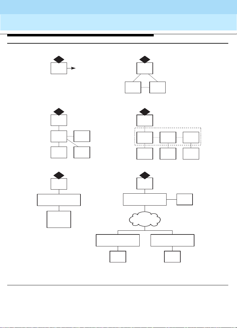
Main System Configuration
Figure 2 shows the following 6 main system configurations:
1. Basic system consisting of a Processor Port Network (PPN) only.
2. Direct-connect system with 3 PNs (1 PPN and 1 or 2 EPNs) connected directly
together.
3. Center Stage Switch (CSS)-connected system with up to 15 EPNs interconnected
by 1 SN to the PPN.
4. CSS-connected system with up to 29 EPNs connected by 2 SNs to the PPN, and
up to 43 EPNs connected by 3 SNs to the PPN.
5. A T M swit ch-c onn ected system with up to 43 EPNs.
6. Multiple ATM switches over a wide area with up to 43 EPNs.
4
DEFINITY Enterprise Communications Server Release 8.2
System Description
555-233-200
Overview of DEFINITY ECS R8
System Components
Issue 1
April 2000
5
1
3
5
To terminals
or trunks
EPN
EPN
PPN
Basic system
PPN
CSS
EPN
CSS-connected system
(PPN, CSS, and up to 15 EPNs)
PPN
ATM Switch
EPNs
(up to 43)
ATM-connected system
(PPN, ATM, and up to
43 EPNs)
Directly-connected system
(PPN and up to 2 EPNs)
(PPN, CSS, and up to 43 EPNs)
ATM Switch
ATM Switch
2
PPN
EPNEPN
4
PPN
CSS
SN
EPNs
CSS-connected system
6
PPN
SN SN
EPNs EPNs
ATM Switch
EPNs
fcdfmsc2 LJK 022200
Figure 2. Main System Configurations
EPNs
ATM-connected system
(PPN, multiple ATMs, and up to
43 EPNs)
EPNs
DEFINITY Enterprise Communications Server Release 8.2
System Description
555-233-200
Issue 1
April 2000
Overview of DEFINITY ECS R8
System Configurations
System Configurations
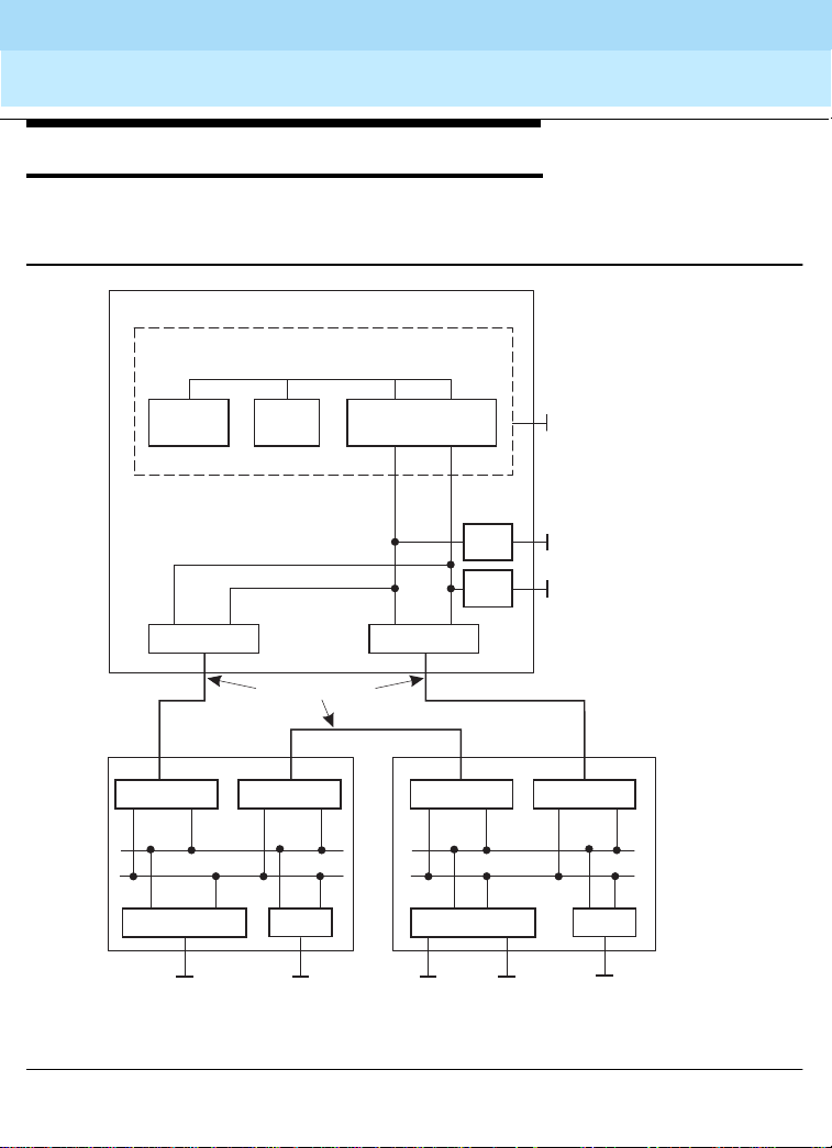
Figure 3 shows a direct-connect system with an SPE in the PPN. Buses route voice and
data calls between externa l trunk s and lines .
PPN
SPE
Processor bus
6
Processor Memory
Packet
Expansion I/O
Fiber optic cable
EPN EPN
Packet
bus
TDM bus TDM bus
Maintenance
Terminal Terminal
cydfcss3 LJK 022299
Ports Ports
External
trunks, lines,
and IP
addresses
Network Control/
Packet Interface
bus
Expansion I/O
TDM
bus
Maintenance
Ports
Ports
Expansion I/OExpansion I/OExpansion I/OExpansion I/O
Packet
bus
External
trunks, lines,
and IP
addresses
Terminal
External trunks,
lines, and IP
addresses
External
trunks, lines,
and IP
addresses
Figure 3. Components of a Direct-Connect System
DEFINITY Enterprise Communications Server Release 8.2
8
System Description
555-233-200
Overview of DEFINITY ECS R8
System Configurations
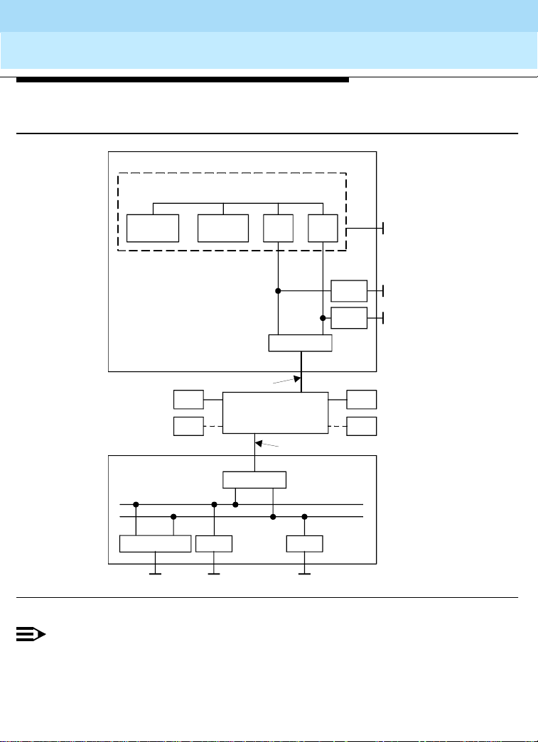
Figure 4 shows a system with the added CSS to route voice and data calls between
external trunks and lines .
PPN
SPE
Processor bus
Issue 1
April 2000
7
Processor Memory
Fiberoptic cable
Typical
Packet bus
Maintenance
Ter minal
Ports Ports
External trunks andlines
Packet
bus
CSS
Expansion I/O
I/O I/O
Expansion I/O
T1 or E1
EPN
(Port network)
TDM bus
TDM
bus
Ports
Ports
Terminal
External
trunks
and lines
EPNEPN
EPNEPN
cydfcnf1 RPY 02099
Figure 4. Components of a CSS-Connected System
NOTE:
The components of an A TM-connected system are similar to those shown
in Figure 4. However, in an ATM-connected system, the CSS is replaced
with an ATM switch or switches and each Expansion I/O is replaced with a
TN2305 or TN2306 circuit pack.

DEFINITY Enterprise Communications Server Release 8.2
System Description
555-233-200
April 2000
Overview of DEFINITY ECS R8
System Configurations
Switch Processing Element (SPE)
When a device, such as a telephone, goes off-hook or signals call initiation, the SPE
receives a signal from the port circuit connected to the device. The digits of the called
number are collected and the switch is set up to make a connection between the calling
and called devices.
The SPE consists of the following control circuits connected by a processor bus:
■
Processor:
processor. The TN790 processor circuit pack is used in R8si systems. The TN798
is used in R8csi systems. The UN332C is used in R8r systems.
■
Memory:
(ROM) and 16 Mbytes of Dynamic Random Access Memory (DRAM) resident on
the processor circuit pack. R8r systems require 3 TN1650B memory circuit packs
to provide a total of 96 Mbytes of DRAM.
■
Storage:
memory on a PCMC IA me mory card. In R8r syste ms, t he dis k dri ve is a non volati le
system bootstrap and translation storage device. A R8r system can use an optic
drive as backup storage.
■
Input/output (I/O) circuits:
division multiplexing bus and packet bus.
■
Maintenance interface:
monitors power failure, clock signals and temperature sensors.
All R8 systems use a Reduced Instruction Set Computer (RISC)
R8csi and R8si systems use 16 Mbytes of flash Read Only Memory
In all R8 systems except R8r, translations are stored in nonvolatile
These act as interfaces between the SPE and the time
connects the system to an administration terminal and
Issue 1
8
Port Network (PN)
The Port Network (PN) consists of the following components:
■
Time Division Multiplexing (TDM) bus:
channel available per bus. Runs internally throughout each PN and terminates on
each end. Consists of two 8-bit parallel buses: bus A and bus B. These buses carry
switched digiti zed v oice and data s ignal s an d con trol s ignal s am ong a ll po rt circ uits
and between port circuits and the SPE. The port circuits place digitized voice and
data signals on a TDM bus. Bus A and bus B are normally active simultaneously.
Has 484 time slots, 23 B channels and 1 D

DEFINITY Enterprise Communications Server Release 8.2
System Description
555-233-200
Overview of DEFINITY ECS R8
System Configurations
■
Packet bus:
Runs internally throughout each PN and terminates on each end. It is
an 18-bit parallel b us th at ca rries l og ical lin ks a nd co ntro l mes sages from the SPE,
through port circuits, to endpoints such as terminals and adjuncts.
The packet bus carries logical links for both on-switch and off-switch control
between some specific port circuits in the system; for example, D-channels, X.25,
and remote management terminals. Typically, the csi model does not support the
packet bus. Any MAPD or ISDN application rides the TDM bus. However, in R7
and later csi systems wi th C- LAN, the applications use the pa ck et bu s prov id ed by
the C-LAN board.
■
Port circuits
: form analog/digita l interface s between t he PN and ext ernal trunk s and
devices providing links between these devices and the TDM bus and packet bus.
Incoming analog signals are converted to pulse-code modulated (PCM) digital
signals and placed on the TDM bus by port circuits. Port circuits convert outgoing
signals from PCM to an al og for ex tern al an alog devices. All port ci rcu its c on nect to
the TDM bus. Only specific ports connect to the packet bus.
■
Interfac e circuits
: Located in the PPN and in each EPN. These are types of port
circuits that terminate fiber op tic cab les conn ect ing TDM b uses a nd the pa cket b us
from the PPN cabinet to t he T D M b us es a nd pac ke t bu s o f ea ch EPN cabinet. The
fiber-optic cable a lso c on nec ts the CSS to the PPN and th e EPNs. The se i nter fac e
and cabling terminations provide a transmission path between the port circuits in
different PNs.
In ATM-PNC, the ATM Interface connects each PN to the ATM switch. An
Expansion Interface (EI) circuit pack also terminates each end of a cable
connecting the PPN to an EPN, ea ch end of a cable c onnec ting an EPN to anothe r
EPN, and the PN end of a cable connected between a PN carrier and an SN
carrier.
A Switch Node Interface ( SNI) circu it pac k termi nates t he SN carrie r end of a cable
connected between an SN carrier and a PN.
■
DS1 converter
: Converts from a fiber interface to a DS1 interface between PNs for
DS1 remoting.
■
Service circuits
: Connect to an external terminal to monitor, maintain, and
troubleshoot the sys tem. Al so pro vide tone pro duction and detectio n as w ell a s cal l
classification, modem pooling, recorded announcements, and speech synthesis.
Issue 1
April 2000
9

DEFINITY Enterprise Communications Server Release 8.2
System Description
555-233-200
Issue 1
April 2000
Overview of DEFINITY ECS R8
System Configurations
Center Stage Switch (CSS)
Figure 5 shows the CSS linkin g the PPN to EPNs by th e SNI c ircuit pac ks in a SN carrie r.
A SN reduces the amount of interconnect cabling between the PPN and the EPNs by
acting as a
A system using a C SS c an c onn ect fr om 3 to 43 PNs. The CSS can cons is t of up to 3 SN
carriers. The CSS can also consist of 2, 4, or 6 SN carriers (duplicated SNs) in a
critical-reliability system.
Each SN contains from 1 to 16 SNI circuit packs. Each interface can connect to a PN or
another SN using fiber-optic cable. One interface always connects to the PPN and 1
connects to each EPN.
hub
to distribute cabling.
PPN
Switch Node
(1 to 16 SNIs)
SNI SNI SNI SNI SNI
10
EPN EPN EPN EPN
cent_ppn_0 RBP 070296
Figure 5. CSS with Switch Nodes (SNs)
In a high reliability system (with duplicated processor), 2 SNI circuit packs connect to the
PPN, allowing up to 15 PNs to connect to 1 SN, up to 20 PNs to connect to 2 SNs, and up
to 25 PNs to connect to 3 SNs, depending on the exact configuration chosen.
ATM Port Network Connectivity (Category A only)
Several Lucent ATM switch types can provide port network connectivity for a DEFINITY
ECS. Non-Lucent ATM switches that comply with the ATM standards set by the ITU can
also provide DEFINITY ECS port network connectivity. In this configuration, TN2305
multi-mode or TN2306 single-mode ATM circuit packs are installed on the port networks
and connected to the ATM switch with the multi- or single-mode fiber specified for the
ATM switch.

DEFINITY Enterprise Communications Server Release 8.2
System Description
555-233-200
Issue 1
April 2000
Overview of DEFINITY ECS R8
Architecture
Architecture
The system consists of 2 main components:
■ The Oryx/Pecos rea l-time, m ultiproce ssing o perating s ystem. Oryx/Pecos supports
the SPE.
■ Applications layer, consisting of 3 major subsystems:
— Call processing: starts up and compl etes call s and mana ges voic e and data in
the system.
— Maintenance: detects faults, recovers operations, and performs tests in the
system.
— System management: controls the internal processes necessary to install,
administer, and maintain the system.
Logical interconnection between system components refers to the 2 kinds of logical links
into the SPE:
■ System links for internal system control
■ Application links used by external applications such as adjuncts
11
DEFINITY ECS Hardware
DEFINITY ECS hardware is covered in detail later in this volume. The following provides
only a general overview of type of equipment used in DEFINITY ECS implementa tions.
Carriers
Carriers hold circuit packs and con nect th em to pow er, the TDM bus, and the packet bus.
There are 5 types:
■ Control carrier (PPN cabinet only)
■ Optional Duplicated Control Carrier (PPN cabinet only)
■ Optional port carrier (PPN and/or EPN cabinets)
■ Optional expansion control carrier (EPN cabinets only)
■ Optional Switch Node Carrier (PPN and/or EPN cabinets)

DEFINITY Enterprise Communications Server Release 8.2
System Description
Overview of DEFINITY ECS R8
DEFINITY ECS Hardware
555-233-200
Issue 1
April 2000
Cabinets
The system cabinets house the carriers and all other components, including the power
supply. A cabinet contains at least 1 carrier in an enclosed shelf with vert ic al s lo ts to hold
circuit packs. The circuit packs fit into connectors that attach to the rear of the slots.
There are 3 cabinet types:
Compact Modular Cabinets (csi)
The Compact Modular Cab inet (CMC) i s only used as a PPN and is a vailable as standard
reliability only (no duplication). It mounts on a wall (preferred) or sits on the floor (with a
floor panel). See Figure 6, ‘ ‘Compac t Modular Ca binet, Flo or Mount (Top) and Wall M ount
(Bottom)’’ on page 13.
12

DEFINITY Enterprise Communications Server Release 8.2
System Description
555-233-200
Overview of DEFINITY ECS R8
DEFINITY ECS Hardware
scdfflor KLC 061397
Issue 1
April 2000
13
scdfovri KLC 061397
Figure 6. Compact Modular Cabinet, Floor Mount (Top) and Wall Mount (Bottom)

DEFINITY Enterprise Communications Server Release 8.2
n
7
System Description
555-233-200
Issue 1
April 2000
Overview of DEFINITY ECS R8
DEFINITY ECS Hardware
The CMC carrier con tain s un iversa l port slots . The pr ocessor circu it pack res ides in s lot 1
and the tone-clock circuit pack resides in slot 2 of the A cabinet. The AUX connector on
the side of the carrier provides power for 1 attendant console and 1 emergency transfer
panel.
Single-Carrier Cabinets (si, r)
Up to 4 Single-Carrier Cabinets (SCC) can be stacked to form a single PN. DEFINITY
ECS si supports a stack of up to 3 cabinets. See Figure 7, "Typical Single-Carrier
Cabinet".
Single-Carrier Cabinets come in any of 4 configurations:
■ A basic control cabi net that contai ns a TN 790B proc esso r, tone clock, and a power
converter (si model only)
■ An expansion control cabinet that contains additional port circuit packs, interfaces
to the PPN, a maintenance interface and a power converter
■ A duplicated control cabinet that co nta ins the same equipment as the basic c ont rol
cabinet (an SCC cannot be used for duplication on an r model)
■ A port cabinet that contains port circuit packs and a power converter
14
Circuit packs
Figure 7. Typical Single-Carrier Cabinet
Power
converter
Air circulatio
vents
scdf001 KLC 06059

DEFINITY Enterprise Communications Server Release 8.2
System Description
555-233-200
April 2000
Overview of DEFINITY ECS R8
DEFINITY ECS Hardware
Multi-Carrier Cabinets (si, r)
A Multi-Carrier Cabinet (MCC) is a 70 in. (178 cm) cabinet that has up to 5 carriers (see
Figure 8, "Typical Multi-Carrier Cabinet"). The 3 types of Multi-Carrier Cabinets are as
follows:
■ PPN cabinet contains the ports, SPE, an interface to an EPN cabinet, and/or a
CSS.
■ EPN cabinet contains additional ports, interfaces to the PPN and other EPN
cabinets, the maintenanc e interfa ce, and opt ional in terface s to other EPN ca binets
and/or a switch node (in an SN in a CSS-connected system).
■ Auxiliary cabinet contains equipment used for optional, system-related hardware,
such as rack-mount equipment.
Issue 1
15
Figure 8. Typical Multi-Carrier Cabinet

DEFINITY Enterprise Communications Server Release 8.2
System Description
Overview of DEFINITY ECS R8
Comparing System Versions
555-233-200
Comparing System Versions
To compare the differences between the system version and the carrier version, see
Table 1 and Table 2.
Table 1. System Versions
System PPN Maximum EPNs Connection Metho d
Release 8csi 1 0 Does not apply
Release 8si 1 2 Direct (fiber only)
Release 8r 1 43 Direct, CSS or ATM
Table 2. Carriers
Carrier Type R8csi R8si R8r
Basic control PPN PPN PPN
Duplicated control Does not apply PPN PPN
Port PPN PPN and EPN PPN and EPN
Expansion control Does not apply EPN EPN
Issue 1
April 2000
16
Continued on ne xt page
Integrating Adjunct, Peripheral, and Third-Party Products
The ProductName can work with a wide range of external equipment, applications, and
peripherals. It provides extensive support for third-party equipment and applications,
such as external ringing equipment and music-on-hold systems. The CallVisor
Adjunct-Switch Application Interface (Category A only) gives independent application
developers access to DEFINITY ECS features and routing information from within their
own applications.

DEFINITY Enterprise Communications Server Release 8.2
System Description
555-233-200
Overview of DEFINITY ECS R8
Integrating Adjunct, Peripheral, and Third-Party Products
Supported Terminals
■ 300-series attendant consoles (301A, 302A, 302B, 302C)
■ 500-, 2500-, 6200-, 7100-, 8100-, 9100-series analog voice terminals (some 7100
series sets may not be available)
■ 602/603/606 CallMaster sets. The 603 and 606 terminals display the full 8-bit
OPTREX character set of graphical characters, including Eurofonts, and the
Japanese katakana character alphabet. (some 602 and 603 CallMaster sets may
not be available)
■ The 6400-series 2-wire DCP voice terminals connect to a digital line circuit pack
and allow the use of both I-Channel s for voice. The numbe r of displayed cha racters
is 27 for calls involving a single ID. If more than one party’s ID displays, the ID
truncates to 15 characters.
These terminals also display the full 8-bit OPTREX character set of graphical
characters, including Eurofonts, and the Japanese katakana character alphabet.
■ 7300-series hybrid (some sets may not be available)
■ 7400-series DCP voice terminal (some sets may not available)
■ The 8400-series D CP voice termi nal c onnec ts to a digi tal li ne ci rcuit pack and u ses
one I-channel for voice (the 8411 uses both I-channels). The number of displayed
characters for calls in vol vi ng a s in gle ID i s 2 7. I f m ore than one party’s ID dis pl ay s,
the ID truncates to 15 characters.
This terminal also displays the full 8-bit OPTREX character set of graphical
characters, including Eurofonts, and the Japanese katakana character alphabet.
■ The 7500 series and 8500-series ISDN-BRI sets extend the existing ISDN-BRI to
allow connection of terminals designed to a variety of BRI specifications.
■ 9000-series cordless sets (TransTalk 9000)
■ The 9400-series DCP terminals 9403B, 9410D, and 9434D display the full 8-bit
OPTREX character set of graphical characters, including Eurofonts, and the
Japanese katakana character alphabet. The number of non-United States
displayed characters is 27 for call s involv ing a singl e ID. If more than o ne party’ s ID
displays, the ID truncates to 15 characters.
■ 9601 DEFINITY Wireless Business Syste m term ina l
Issue 1
April 2000
17
NOTE:
Other terminals are available. Contact your Lucent Technologies representative
for more information.

DEFINITY Enterprise Communications Server Release 8.2
System Description
555-233-200
Issue 1
April 2000
Overview of DEFINITY ECS R8
Duplication
IP SoftPhones
IP SoftPhones extend the level of DEFINITY services. They turn a PC or a laptop into an
advanced telephon e. You can place calls, t ake call s and han dle multi ple call s on your PC.
There are 4 types of telephones available. They are:
Telecommuter application -- a multifunction station that runs on a PC plus a
conventional telephone. Call control is done on the SoftPhone and the voice path
is on the DCP se t. T his IP SoftPh one is i nten de d to be used by home workers w ho
require PSTN quality audio. The MedPro board is not used in this application.
Road-warrior applicati on -- a multi function stati on that is based e ntirely on t he PC.
It is used when there is only a single telephone line available to access the IP
network and the DEFINITY. This IP SoftPhone is intended to use by your traveling
associates. The MedPro board is used for the road-warrior application.
CentreVu IP Agent -- This SoftPh one is the t elecomm uter appli cation th at has b een
configured to use the CentreVu IP Agent user interface software. It is used as a
Call Center agent station.
Native H.323 -- This is an IP-connected SoftPho ne running off-the-shelf H.323
software. It operates as a single-line phone with limited features, which are
activated by Feature Access Codes.
18
Duplication
Duplication is a strategy to create fully redundant systems. Duplication minimizes single
failure points that can interrupt call processing. Three system duplication options are
available:
■ Standard reliability--this is the only reliability configuration option available for
DEFINITY ECS csi model. Will not duplicate Tone-Clock(s), the Control Carrier or
any inter-PN co nnectivity.
■ High reliability--duplicates the hardware that is associated with the SPE. The
Control Carrier is duplicated, which provides duplicate SPEs and Tone-Clocks.
Inter-PN connectivity and EPN Tone-Clocks are not duplicated. The strategy is to
duplicate items th at are associ ated with the SPE so that a s ingle fau lt will not ca use
the loss of the SPE. High reliability is available with DEFINITY si and r models.

DEFINITY Enterprise Communications Server Release 8.2
System Description
Overview of DEFINITY ECS R8
Administration
■ Critical reliability--is available with DEFINITY si and r models and requires the full
duplication of the SPE, inter-PN connectivity and the Tone-Clocks (Category A
only).
■ ATM Network Duplication--requires full duplication of the inter-PN connectivity and
the Tone-Clocks (Category A only).
As duplication inc r eases , the maximum number of port carriers and port circui t pa ck s per
cabinet decreases. The information regarding the needed hardware can be found in
Chapter 3.
555-233-200
Issue 1
April 2000
Administration
A management terminal connects to the system for administrative purposes. Enter
commands at the terminal to display administration screens (forms). The forms list data
and allow you to add, change, and remove system and voice-terminal features. For
system administration information, consult the
Server Release 8 Administrator’s Guide.
DEFINITY Enterprise Communications
Connecting with TCP/IP Networks
19
LAN Gateway
With the optional J58890MA-1List 2 LAN Gateway circuit-pack assembly installed,
DEFINITY ECS works with PC/LAN-based communications applications that support the
CallVisor Adjunct-Switch Application Interface (ASAI) (Category A only).
C-LAN
TCP/IP Connectivity is provided over Ethernet or Point-to-Point Protocol (PPP) to
adjuncts such as CMS Call Center and INTUITY AUDIX and for DCS connectivity. The
C-LAN circuit pack (TN799) provides a "bridge" from the TDM bus to the packet bus on
DEFINITY ECS csi.

DEFINITY Enterprise Communications Server Release 8.2
System Description
Overview of DEFINITY ECS R8
Connecting with ATM Port Networks (Category A only)
555-233-200
Issue 1
April 2000
Network Control/Packet Interface
Communicates control channel messages between the processor circuit pack and the
distributed network of port circui t packs on the TDM bu s. The NetPkt ci rcuit pack (TN7 94)
provides 8 asynchronous data channels that process and route information directly from
the processor circuit pack to customer-connected equipment.
PassageWay Integrated Voice/Data-Workstation Applications
PassageWay applications make the features of the DEFINITY ECS telephone system
available from the Window s d esktop. With Pa ssag eW ay and the D EFIN ITY LAN gate way
implemented, a Call Center application could, for instance, let Agents access all
job-related resources—the order-processing database, company World Wide Web site,
phone system, voicemail system, and fax machine—from a single interface on the PC.
Connecting with ATM Port Networks
(Category A only)
20
ATM-PNC (Category A only)
ATM Port Network Connectivity (ATM-PNC) provides an alternative to either the direct
connect or Center Stage Switch configurations for connecting the Processor Port
Network (PPN) to one or m ore Ex pan si on Port Netw o rks (EPNs ). ATM-PNC replaces the
Center Stage Switch in a DEFINITY R8r network with an Asynchronous Transfer Mode
(ATM) switch. ATM-PNC is available with all three DEFINITY ECS reliability options—
standard, high, and critical.
ATM-PNC integrates delivery of voice, video, and data via ATM over a common large
bandwidth LAN, providing reduced infrastructure cost and improved network
manageability. ATM-PNC uses standards-based open interfaces that can be provisioned
with either new or existing DEFINITY ECS systems and is ATM-ready for future
expansion.

DEFINITY Enterprise Communications Server Release 8.2
System Description
555-233-200
Issue 1
April 2000
Overview of DEFINITY ECS R8
Connecting with ATM Port Networks (Category A only)
ATM-CES (Category A only)
ATM-CES (Circuit-Emulation Service) lets the DEFINITY ECS emulate an ISDN-PRI
trunk on an ATM facility. These virtual trunks can serve as integrated access, tandem, or
tie trunks. ATM-CES trunk emulation maximizes port n etwork capacities by conso li dati ng
trunking. For example, the CES interface can define up to ten virtual circuits for tie-line
connectivity, consolidating onto one circuit card netwo rk conne ctivity tha t usually requ ires
multiple circuit packs.
ATM WAN (Category A only)
ATM Wide Area Network (ATM WAN) extends the Port Network Connectivity (PNC)
beyond a single ATM switch. This allows you to use either a private ATM network, public
WAN, or a combination of both. Several networked ATM devices can be used as
effectively as a single ATM switch for inter-port network connectivity. ATM WAN is
supported by the "Multiple Location" feature, where port network cabinets can be
administered as se parate loca tions; how ever , it is not required . You can use multiple A TM
switches without multiple locations administered.
21
EPN
PPN
PNC
PNC
CES
ATM
backbone
switch
Network management
platform
ATM
Enterprise
switch
Wide
area ATM
network
ATM
Enterprise
switch
PPN
CES
cydfatm2 KLC 102299
DEFINITY Enterprise Communications Server Release 8.2
System Description
555-233-200
Issue 1
April 2000
Overview of DEFINITY ECS R8
IP Solutions (Category A only)
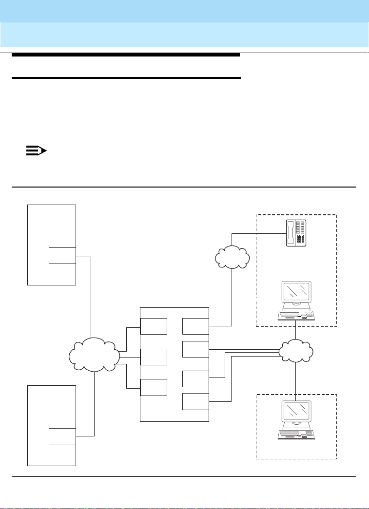
IP Solutions (Category A only)
DEFINITY ECS IP Solutions b rings toge ther the flex ibility o f IP networks wi th the richn ess
of voice communication. It allows investment protection and optimization in IP, ATM, and
PSTN networks. Full applicati ons, feature s, and managem ent capabil ities are carried into
the IP environment. Remote workers have full access to communication system features
from their PCs. Figure 1 sh ows the trun k and line connections av ail ab le with IP Solutions.
NOTE:
Voice qua lity can and will vary ba sed on LAN conditio ns, w hic h are extraneous to
IP Solutions.
22
DEFINITY R8
TN802B
MedPro
Mode
H.323
Trunk
LAN/WAN
DEFINITY R7
IP Trunk
TN802B
IP Trunk
Mode
Figure 9. IP Solutions
DEFINITY R8
TN802B
MedPro
Mode
C-LAN
TN802B
IP Trunk
Mode
DS1
C-LAN
TN802B
MedPro
Mode
C-LAN
cydfipsl EWS 022800
PSTN
Telecommuter application
VoiceTerminal
DEFINITY IP Softphone
or CentreVu IP Agent
LAN/WAN
DEFINITY IP Softphone
with H.323 voice application
Road-warrior application

DEFINITY Enterprise Communications Server Release 8.2
System Description
555-233-200
Issue 1
April 2000
Overview of DEFINITY ECS R8
IP Solutions (Category A only)
As shown in Figure 1, D EFINITY ECS IP Solutions supports IP c onnec tiv it y fo r two types
of trunks and three types of IP Softphones.
DEFINITY ECS IP Solutions is implemented using the TN802/TN802B IP Interface
assembly, which is a Windows NT server that resides on the IP-Interface circuit pack
inside the DEFINITY ECS. The TN802B IP Interface, introduc ed in R elease 8, operates in
either the IP Trunk mode (for IP trunk connections) or in the MedPro mode (for H.323
trunk connections and H.323 voice processing for IP softphones). The TN802
IP-Interface, introduced in Release 7, operates only in the IP Trunk mode. The TN802B
defaults to IP Trunk mode and is backward compatible with Release 7. The MedPro
mode requires the new TN799B C-LAN circui t pack.
With Release 7 software, or with Release 8 software configured as Release 7 (that is, R8
used as a bugfix for R7), the TN802B can be used only in the IP Trunk mode. With
Release 8 software, the TN802B can be used in either mode but each TN802B can
operate in just one of the two modes at a time; that is, all trunks supported by the same
TN802B must all be operating in the same mode. DEFINITY ECS supports multiple
TN802Bs operating in a mixtu re of the tw o modes or a combi nation of TN802 s (opera ting
in the IP Trunk mode) and TN802Bs (operating in either mode).
The IP Trunk and MedPro modes are not interoperable; that is, the TN802B in MedPro
mode cannot communicate with another TN802B in IP Trunk mode or with a TN802.
23
Trunks
DEFINITY ECS IP Solutions supports two trunk configurations:
■ H.323 Trunk
■ IP Trunk
H.323 Trunk
MedPro mode supports the H.323 version 2 protocol and interoperates with H.323
version 2 endpoin ts, incl uding s tations, trunks, a nd gatewa ys. The TN80 2B IP In terface in
Medpro mode enables H.323 trunk service using IP connectivity between two DEFINITY
ECS systems. H.323 trunk groups can be configured as DEFINITY-specific tie trunks
supporting ISDN trunk features such as DCS+ and QSIG, or as generic tie trunks
permitting interconnection with other vendors’ H.323 v2-compliant switches, or as
direct-inward-dial (DID) type of “public” trunks providing access to the switch for
unregistered users. TheTN802B in MedPro mode requires the TN799B for signaling.

DEFINITY Enterprise Communications Server Release 8.2
System Description
555-233-200
Issue 1
April 2000
Overview of DEFINITY ECS R8
IP Solutions (Category A only)
IP Trunk
In Release 8, the IP Trunk mode will typically be chosen for interoperability with existing
TN802 (as opposed to the TN802B) IP Interface circuit packs.
The IP Trunk m ode allows trunk groups to be defin ed as DS1 t ie lines b etween DEFI NITY
ECS systems over a virtual private network (VPN). Each IP Interface circuit pack in IP
Trunk mode provides a basic twelve-port package that can be expanded up to a total of
30 ports.
The benefits of IP Trunk include a reduction in long distance voice and fax expenses,
facilitating global communications, providing a full-function network with data and voice
convergence and optimizing networks by using the available network resources.
Each TN802 or TN802B in IP Trunk mode requires a connection to a modem and an
incoming line for Lucent remote access. The TN802 (but not the TN802B in IP Trunk
mode) also requires direct access to the NT server on the TN802 hard disk using
pcANYWHERE, version 8 or later. A TN802B in the IP Trunk mode does not require the
TN799B.
IP Softphones
DEFINITY IP Softphones operate on a PC equipped with Microsoft Windows 95/98/NT
and with TCP/IP connectivity to DEFINITY ECS.
DEFINITY IP Solutions supports three IP Softphone configurations:
■ Road-warrior application (voice over IP)
■ Telecommuter application (dual-connection)
■ CentreVu IP Agent (dual-connection)
■ Native H.323
24

DEFINITY Enterprise Communications Server Release 8.2
System Description
Overview of DEFINITY ECS R8
555-233-200
Issue 1
April 2000
IP Solutions (Category A only)
Road-warrior applicatio n
The road-warrior application of the DEFINITY IP Softphone enables travellers to use the
full DEFINITY ECS feature set from temporary remote locations anywhere in the world
such as a hotel room. The road-warrior application consists of two software applications
running on a PC that is connected to DEFINITY ECS over an IP network. The single
network connection between the PC and DEFINITY ECS carries two channels, one for
the signaling path and one for the voice path. DEFINITY IP Softphone software handles
the call signaling and an H.323 V2-compliant audio application, such as Microsoft
NetMeeting, handles the voice communications. The user places and receives calls via
the IP Softphone interface on the PC and uses a headset connected to the PC (or the
PC’s microphone and speakers) to speak and listen.
With the road-warrior application, NetMeeting has been configured to run in the
background and use only the audio portion of the applications. The data collaboration
feature of NetMeeting can be used as a stand-alone application but it is disabled during
an IP Softphone session.
On DEFINITY ECS, the roa d-warrior app lication of th e IP Softpho ne requires the TN799B
(C-LAN) for signaling and the TN802B IP Interface circuit pack assembly running in
MedPro mode for voice processing. Each VOIP Softphone requires the administration of
two stations — an H.323 station and one of the types of DCP station.
25
Telecommuter application
The telecommuter application of the DEFINITY IP Softphone enables telecommuters to
use the full DEFINITY ECS feature set from home. It consists of a PC and a telephone
with separate connections to DEFINITY ECS. The PC is connected to DEFINITY ECS
over an IP network to provide the signaling path. The PC runs the DEFINITY IP
Softphone software to provide the user interface for call control. A standard telephone is
connected to DEFINITY ECS over the public switched telephone network (PSTN) to
provide a high-quality voice path. The user places and receives calls via the IP Softphone
interface on the PC and uses the telephone handset to speak and listen.
On DEFINITY ECS, the telecommuter application of the IP Softphone requires the
TN799B (C-LAN) for signaling. The TN802B IP Interface is not used for the telecommuter
application. Each instance of the telecommuter application requires the administration of
two stations — an IP Softphone station and one of the types of DCP station.

DEFINITY Enterprise Communications Server Release 8.2
System Description
555-233-200
Issue 1
April 2000
Overview of DEFINITY ECS R8
International Requi rements
CentreVu IP Agent
The DEFINITY CentreVu IP Agent is a variation of the te lecommuter ap plication. The
CentreVu IP Agent emulates a Lucent CallMaster set and provides use of the call end
capabilities required for Call Center operations from a remote location, such as the
agent’s home.
Native H.323
This is an IP-connected softphone running off-the-shelf H.323 software. It operates as a
single-line phone with limited features, which are activated by Feature Access Codes.
International Requirements
The DEFINITY system complies with the regulations of many countries and supports a
wide range of languag es, incl uding us er-defined languages . These a re a few examples of
the country-specific features that are available:
■ Terminal-display language
■ Tone plans and customizable tones (within selected tone plan)
■ Transmission, conference-loss, and tone-loss plans
■ Ringing
■ 12- or 16-kHz periodic pulse metering (PPM)
■ A-Law or µ-Law companding
■ ISDN and non-ISDN, bit-oriented digital protocols
■ Analog, line and trunk port impedances
■ Gain and loss characteristics
■ 1.544-Mbps T1 and CEPT 2.048-Mbps E1 protocols
■ DS1 port administration (DS1 framing, signaling, line coding, and companding on
trunks).
CEPT
The switch has many other non-USA features.
26

DEFINITY Enterprise Communications Server Release 8.2
System Description
Site Requirements
Floor Area
555-233-200
Issue 1
April 2000
2 —Site Requirements
This section describes the wall and floor area, and loading specifications for various
DEFINITY ECS cabinets.
Floor Area
For maintenance access, floor plans typically allocate space around the front, ends, and
rear of the cabinets. Floor area requirements vary between cabinets. Dimensions and
clearances for all cabinet configurations are listed in Table 3.
Table 3. Cabinet Dimensions and Clearances
Cabinet Type Height Width Depth Clearance
Compact Modular
1-cabinet
2-cabinets
3-cabinets
25.5 in.
(64.8 cm)
51 in.
(129.6 cm)
76.5 in.
(194.4 cm)
24.5 in.
(62.2 cm)
24.5 in.
(62.2 cm)
24.5 in.
(62.2 cm)
12 in.
(30.5cm)
12 in.
(30.5 cm)
12 in.
(30.5 cm)
Left, Right, and
Front 12 in.
(30.5 cm)
27
Continued on next page

DEFINITY Enterprise Communications Server Release 8.2
System Description
555-233-200
Site Requirements
Floor Area
Table 3. Cabinet Dimensions and Clearances — Continued
Cabinet Ty pe Height Width Depth Clearance
Single-Carrier
1-cabinet
20 in.
(51 cm)
27 in.
(69 cm)
22 in.
(56 cm)
38 in. (97 cm)
between cabinet
and wall
Issue 1
April 2000
28
2-cabinets
3-cabinets
4-cabinets
Multi-Carrier
1
Cable slack manage r
3
DC power cabinet
20 in.
39 in.
(99 cm)
58 in.
(1.5 m)
77 in.
(2 m)
70 in.
(1.8 m)
2
7 in.
(18 cm)
(51 cm)
27 in.
(69 cm)
27 in.
(69 cm)
27 in.
(69 cm)
32 in.
(81 cm)
32 in.
(81 cm)
27 in.
(69 cm)
22 in.
(56 cm)
22 in.
(56 cm)
22 in.
(56 cm)
28 in.
(71 cm)
38 in.
(97 cm)
22 in.
(56 cm)
Rear 38 in.
(97 cm)
Front 36 in.
(91 cm)
38 in. (97 cm)
Front and Rear
Continued on n e xt page

DEFINITY Enterprise Communications Server Release 8.2
System Description
555-233-200
Site Requirements
Floor Area
Table 3. Cabinet Dimensions and Clearances — Continued
Cabinet Type Height Width Depth Clearance
Large battery cabinet
100 Amp
27 in.
(69 cm)
55 in.
(140 cm)
21 in.
(53 cm)
38 in. (97 cm)
Front and Rear
200 Amp
42 in.
(107 cm)
55 in.
(140 cm)
21 in.
(53 cm)
300 Amp
42 in.
(107 cm)
55 in.
(140 cm)
21 in.
(53 cm)
400 Amp
57 in.
(145 cm)
55 in.
(140 cm)
21 in.
(53 cm)
Continued on next page
1.
Includes the auxiliary cabinet, the global AC cabinet, and the global DC cabinet.
2.
Used with Multi-Carrier and Single-Carrier cabinets.
3.
Requires a floor area of 8 square feet (0.74 square m). Also requires 38 in. (97 cm)
between cabinet and wall.
Issue 1
April 2000
29

DEFINITY Enterprise Communications Server Release 8.2
System Description
555-233-200
Issue 1
April 2000
Site Requirements
Floor Load Requirements
Floor Load Requirements
The equipment room f loor m ust m eet the com merci al flo or load ing c ode o f at least 50 lb s.
per square foot (242 kg per square meter). Floor pla ns typically allocate space around the
front, ends, and rear (if necessary) of the cabinets, for maintenance access. Additional
equipment room floor support may be required if the floor load is greater than 50 lbs. per
square foot (242 kg per square meter). See the table below.
Table 4. Cabinet Weights and Floor Loadings
Type Weight Floor Loading Remarks
Compact
Modular
Single-Carrier 125 lb. (56 kg) 31 lb./sq. ft. (148.9 kg/m
Multi-Carrier 200-800 lb. (90-3 63 kg) 130 l b./s q. ft. (6 24.2 kg/m
100-Amp
battery
200-Amp
battery
300-Amp
battery
400-Amp
battery
50 lb. (22.7 kg) Typically wall
mounted—one
cabinet can be
floor-mounted.
2
)
2
) Includes
Auxiliary, Global
AC and Global
DC cabinets
2
400 lb. (181 kg) max. 180 lb./sq. ft. (871.2 kg/m
815lb. (370 kg) max. 328 lb./sq. ft. (1587.5
1480 lb. (671 kg) max. 476 lb./sq. ft. (2303.8
kg/m
kg/m
2
)
2
)
1580 lb. (717 kg) max. 625 lb./sq. ft. (3025 kg/m
)
2)
30
Continued on next page

DEFINITY Enterprise Communications Server Release 8.2
System Description
Site Requirements
Floor-Plan Guidelines
555-233-200
Issue 1
April 2000
Floor-Plan Guidelines
DEFINITY ECS floor plans vary with the size and shape of the equipment room and the
extent of future growth. Future growth includes a new or upgraded system, adjuncts and
peripherals, and the cross-connect field. See ‘‘Cross-Connect Field’’ on page 41.
For floor standing cabinets, reserve the area behind a cabinet for the cross-connect field
and the cable slack manager. For wall mounted cabinets, reserve the area beside the
cabinets for the cross-c onnec t field. F igure 10 through Figure 15 show ty pical floo r plans .
All dimensions are shown in inches. Refer to Table 11 for power requirements.
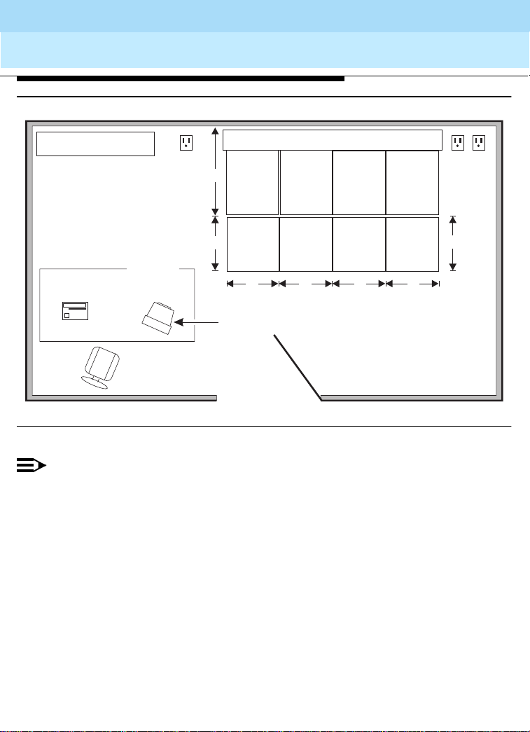
Compact Modular Cabinet (CMC) Configuration Guidelines
The cross-connect field is either to the rear or right of the cabinet. To allow service
access, the table for the management terminal and optional printer is away from the
equipment area. See Figure 10 and ‘‘Table Area’’ on page 40 for requirements. In an
installation where no cross-connect field is present, an cross-connect field can be
installed in the CMC right panel.
The following steps are pre-installation guidelines:
1. Locate the powe r outlet s outs ide th e cros s-con nect fi eld area. The ou tlets m ust n ot
be controlled by a wall switch or be shared with other equipment.
2. Locate the trunk/auxiliary field inside the cross-connect field, if desired.
3. Ground the system. See ‘‘Approved Grounds’’ on page 62.
4. Each cabinet requires either: NEMA 5-15R receptacle
(or equivalent) for United States installations or local IEC 320
cord set (or equivalent) for non-United States installations.
31

DEFINITY Enterprise Communications Server Release 8.2
System Description
555-233-200
Site Requirements
Floor-Plan Guidelines
Issue 1
April 2000
32
12”
Printer
Compact
modular
cabinet
12” 12”25.5”
Table
management
Electrical
outlets
48”
Optional SMT
System
terminal
Cross-connect field
Wall
Figure 10. Typical Compact Modular Cabinet Floor Plan
NOTE:
To provide power for testing equipment and peripherals, locate electrical
outlets at intervals that are in accordance with local codes. Also, ensure
that you locate the main shutoff switch near the door in accordance with
local codes.
fpdftfp4 LJK 121399

DEFINITY Enterprise Communications Server Release 8.2
System Description
Site Requirements
555-233-200
Issue 1
April 2000
Floor-Plan Guidelines
Single-Carrier Cabinet Configuration Guidelines
The cross-connect field can be directly behind the cable slack manager. To allow service
access, the table for the management terminal and optional printer is away from the
equipment area. See Figure 11 and ‘‘Table Area’’ on page 40 for requirements.
The following steps are pre-installation guidelines:
1. Locate the powe r outlet s outs ide th e cros s-con nect fi eld area. The ou tlets m ust n ot
be controlled by a wall switch or be shared with other equipment.
2. Locate the trunk/auxiliary field inside the cross-connect field, if desired.
3. Ground the system. See ‘‘Approved Grounds’’ on page 62.
4. For fiber connections between PNs, use a 20-foot (6.1 m) multimode fiber optic
cable.
5. Install earthquake protection (if required). See ‘‘Earthquake Protection’’ on page
71.
6. Each cabinet requires either: NEMA 5-15R, NEMA 5-20R receptacle (or
equivalent) for United States installations or local
cord set (or equivalent) for non-United States installations.
33

DEFINITY Enterprise Communications Server Release 8.2
System Description
555-233-200
Site Requirements
Floor-Plan Guidelines
Issue 1
April 2000
34
Cross-connect field
Processor
port
network
cabinet(s)
(front)
27"
Optional SMT
Cable
slack
manager
32"
38"
Wall
Printer
LAN
connection
22"
Table
System
management
terminal
Figure 11. Typical Single-Carrier Cabinet Floor Plan
NOTE:
To provide power for testing equipment and peripherals, locate electrical
outlets at intervals that are in accordance with local codes. Also, ensure
that you locate the main shutoff switch near the door in accordance with
local codes.
Electrical
outlets
fpdfscc1 LJK 121399

DEFINITY Enterprise Communications Server Release 8.2
System Description
Site Requirements
555-233-200
Floor-Plan Guidelines
Multi-Carrier Cabinet Configuration Guidelines
The cross-connect field is directly behind the cable slack manager. To allow service
access, the table for the management terminal and optional printer is away from the
equipment area. See Figure 12 and ‘‘Table Area’’ on page 40 for requirements. The
following steps are pre-installation guidelines:
1. Locate the powe r outlet s outs ide th e cros s-con nect fi eld area. The ou tlets m ust n ot
be controlled by a wall switch or be shared with other equipment.
2. For the PPN cabinets, use either a NEMA 5-50R receptacle (or equivalent) or a
NEMA L14-30R receptacle (or equivalent) power outlet or: 220 VAC, 50-60 Hz
power outlet for the Global AC Cabinet.
3. For the Auxiliary Cabinet, use a NEMA 5-20R receptacle (or equivalent).
4. Allow at least 3 feet (91.4cm) of space in front of the cabinet to permit the door to
open.
5. Ground the system. See ‘‘Approved Grounds’’ on page 62.
6. Install earthquake protection (if required). See ‘‘Earthquake Protection’’ on page
71.
7. Locate the LAN connection field inside the cross-connect field, if desired.
8. Fiber connections between PNs use a 20-foot (6.1 m) multimode fiber optic cable.
Issue 1
April 2000
35

DEFINITY Enterprise Communications Server Release 8.2
System Description
555-233-200
Site Requirements
Floor-Plan Guidelines
Issue 1
April 2000
36
LAN connection
Table
Printer
System
management
terminal
Electrical
outlet
38"
28" 28"
Optional SMT
Cross-connect field
Cable
slack
manager
Port
network
cabinet
(front)
32"
manager
(optional)
Auxiliary
cabinet
(optional)
Cable
slack
32"
Wall
fpdfmcc1 LJK 121399
Figure 12. Typical Multi-Carrier Cabinet Floorplan
NOTE:
To provide power for testing equipment and peripherals, locate electrical
outlets at intervals that are in accordance with local codes. Also, ensure
that you locate the main shutoff switch near the door in accordance with
local codes.
Electrical
outlets

DEFINITY Enterprise Communications Server Release 8.2
System Description
555-233-200
April 2000
Site Requirements
Floor-Plan Guidelines
Additional Floor Plans
The following floor plans illustrate recommendations for other possible installations. See
Figure 13, Figure 14, Figure 15, and Figure 16.
Issue 1
37
LAN connection
Table
Printer
System
management
terminal
Electrical
outlet
38"
28"
Optional SMT
Cross-connect field
Cable
slack
manager
PPN
cabinet
(front)
32"
Cable
slack
manager
(optional)
EPN
cabinet
(optional)
32"
Cable
slack
manager
(optional)
Auxiliary
cabinet
(optional)
32"
Wall
fpdftfp1 LJK 121399
Figure 13. Typical Floor Plan with EPN and Auxiliary Cabinet
NOTE:
To provide power for testing equipment and peripherals, locate electrical
outlets at intervals that are in accordance with local codes. Also, ensure
that you locate the main shutoff switch near the door in accordance with
local codes.
28"
DEFINITY Enterprise Communications Server Release 8.2
System Description
555-233-200
Site Requirements
Floor-Plan Guidelines
Issue 1
April 2000
38
LAN connection
Table
Printer
Electrical
outlet
System
management
terminal
38"
manager
28"
Optional SMT
Cross-connect field
Cable
slack
PPN
cabinet
(front)
32"
Cable
slack
manager
(optional)
EPN
cabinets
(optional)
32"
Cable
slack
manager
(optional)
Auxiliary
cabinet
(optional)
32"
Cable
slack
manager
(optional)
Auxiliary
cabinet
(optional)
32"
Wall
fpdftfp3 LJK 121399
Electrical
outlets
28"
Figure 14. Typical Floor Plan with an additional EPN and Auxiliary Cabinets
NOTE:
To provide power for testing equipment and peripherals, locate electrical
outlets at intervals that are in accordance with local codes. Also, ensure
that you locate the main shutoff switch near the door in accordance with
local codes.

DEFINITY Enterprise Communications Server Release 8.2
System Description
555-233-200
Site Requirements
Floor-Plan Guidelines
Issue 1
April 2000
39
LAN connection
Table
Printer
System
management
terminal
Electrical
outlet
38"
28"
Optional SMT
Cross-connect field
Cable
slack
manager
PPN
cabinet
(front)
32"
Cable
slack
manager
(optional)
EPN
cabinet
(optional)
Cable
slack
manager
(optional)
Auxiliary
cabinet
(optional)
32"
Battery
cabinet
(optional)
32"
55" 55"
Battery
cabinet
(optional)
fpdftfp5 LJK 121399
Figure 15. Typical Floor Plan with Battery Cabinets
NOTE:
To provide power for testing equipment and peripherals, locate electrical
outlets at intervals that are in accordance with local codes. Also, ensure
that you locate the main shutoff switch near the door in accordance with
local codes.
Wall
28"
21"

DEFINITY Enterprise Communications Server Release 8.2
System Description
555-233-200
Site Requirements
Floor-Plan Guidelines
Issue 1
April 2000
40
LAN connection
Table
Printer
ATM
switch
38"
28"
System
management
terminal
Optional SMT
Cross-connect field
Cable
slack
manager
PPN
cabinet
(front)
32"
Cable
slack
manager
(optional)
EPN
cabinet
(optional)
32"
Cable
slack
manager
(optional)
Auxiliary
cabinet
(optional)
32"
Wall
fpdftfp6 LJK 121399
Figure 16. Typical Floor Plan with ATM Switch (Category A only)
NOTE:
To provide power for testing equipment and peripherals, locate electrical
outlets at intervals that are in accordance with local codes. Also, ensure
that you locate the main shutoff switch near the door in accordance with
local codes.
Electrical
outlet
28"
Table Area
Reserve the table area in the equipment room for the management terminal and optional
printer , if s o eq uip ped. Terminals require approximately 3.2 squ are fe et (0 .3 s qua re m ) of
area.

DEFINITY Enterprise Communications Server Release 8.2
System Description
Site Requirements
555-233-200
Issue 1
April 2000
Environmental Considerations
Cross-Connect Field
The cross-connect field equipment is located a specified distance from the DEFINITY
cabinets and must meet specific requirements. An optional cross-connect field can be
installed in the CMC right panel.
For new installations, Lucent Technologies personnel may install the cross-connect field.
For more details about the cross-connect field and other site requirements, refer to the
following documents:
■
DEFINITY Communications System Generic 1 and Generic 3 Main Distribution
Field Design
■
DEFINITY Communications System Generic 3 Planning and Configuration
555-230-601
, 555-230-630
,
NOTE:
The cross-connect field is wired to the external environment (trunks and lines
outside of the building) by telephone company personnel.
Environmental Considerations
41
This section details the environmental considerations for the Multi-Carrier and
Single-Carrier cabinets. For information about the DEFINITY Wi rele ss Bus ine ss Syst em,
refer to Appendix A.
Heat Dissipation
Typical heat dissipation Compact Single-Carrier, Single-Carrier, Multi-Carrier ar e shown
in Table 5.

DEFINITY Enterprise Communications Server Release 8.2
System Description
555-233-200
Site Requirements
Environmental Considerations
Table 5. Typical Heat Dissipation for Various Cabinet Configurations
Issue 1
April 2000
42
Cabinet type
Compact
Number in
Stack
1 No 202 810 kg 234
With
Terminals? BTUs/Hour
Gram-Cals./
Hour Watts
Modular
Yes 378 1500 kg 439
Single-Carrier 1 Yes 438 1700 kg 499
4 (max.) Yes 1436 5700 kg 1672
Multi-Carrier 1 No 1058 4200 kg 1232
Yes 1662 6600 kg 1935
Continued on n e xt page
Altitude and Air Pressure
At altitudes above 5,000 feet (1,525 meters), the maximum short-term temperature limit
reduces by 1
(1,525 meters). For example: at sea level, the maximum short-term temperature limit is
120o F (49o Celsius). At 10,00 0 feet (3 ,050 met ers), th e maxi mum sh ort-term te mperature
limit is 115
The normal operating air pressure range is: 9.4 to 15.2 psi (lbs. per sq. in.) (648 to 1,048
millibars).
o
Fahrenheit for each 1,000 feet (305 meters) of elevation above 5,000 feet
o
F (46o C).
Temperature and Humidity
Install the equipment in a well-ventilated area. Maximum equipment performance is
achieved at an ambient room temperature between 40 and 120
o
F (4o and 49o C) for
short term operatio n (n ot mo re than 7 2 c on se cut iv e h ours o r 1 5 days in a year) and up to
110o F (43o C) for continuous operation.
o
The relative humidity range is 10 to 95% at up to 84
relative humidity decreases from 95% down to 32% at 120
outside these limits may reduce system life or affect operation. The recommended
temperature and humidity range is 65
o
to 85o F (18o to 29o C) at 20 to 60% relative
F (29o C). Above this, maximum
o
F (49o C). Installations
humidity. See Table 6.

DEFINITY Enterprise Communications Server Release 8.2
System Description
555-233-200
Site Requirements
Environmental Considerations
Table 6. Temperature and Relative Humidity
Issue 1
April 2000
43
Room Temperature
(Degrees Fahrenheit)
Room Temperature
(Degrees Celsius) Relative Humidity (%)
40 to 84 4.4 to 28.8 10 to 95
86 30.0 10 to 89
88 31.1 10 to 83
90 32.2 10 to 78
92 33.3 10 to 73
94 34.4 10 to 69
96 35.6 10 to 65
98 36.7 10 to 61
100 37.8 10 to 58
102 38.9 10 to 54
104 40.0 10 to 51
106 41.1 10 to 48
108 42.2 10 to 45
110 43.3 10 to 43
112 44.4 10 to 40
114 45.6 10 to 38
116 46.7 10 to 36
118 47.8 10 to 34
120 48.9 10 to 32
Continued on next page

DEFINITY Enterprise Communications Server Release 8.2
System Description
Site Requirements
555-233-200
April 2000
Environmental Considerations
Air Purity
The Compact Modular Cabinet, Single-Carrier and Multi-Carrier Cabinets contain an air
filter to reduce particulates flowing through the equipment. Do not install the cabinet
where the air may be contaminated by excessive dust, lint, carbon particles, paper fiber
contaminants, or metallic contaminants. For example, do not install the cabinet near
paper handling equipment such as copiers and high-speed printers, which introduce
paper dust and print particles into the environment. Corrosive gases above the levels in
Table 7 must be avoided.
Table 7. Allowable Concen trati ons for Atmospheric Contaminants
Contaminant Average Concentration Not to Exceed
All particulate matter 185 micrograms/cubic meter
Nitrate 12 micrograms/cubic meter
Total hydrocarbons equivalent to methane 10 ppm (parts per million)
Sulphur dioxide 0.20 ppm (parts per million)
Oxides of nitrogen 0.30 ppm (parts per million)
Total oxidants equivalent to ozone 0.05 ppm (parts per million)
Hydrogen sulfide 0.10 ppm (parts per million)
Issue 1
44
Lighting
Lighting must be bright enough to allow personnel to perform their tasks. The
recommended light intensity is 50 to 70 footcandles (538 to 753 lumens/m
Occupational Safety and Health Act (OSHA) standards.
2
) to meet the
Radio Frequency Noise
Noise is introduced into the system through trunk or station cables, or both.
Electromagnetic fields near the system control equipment may cause system noise.
Place the system and cable runs in areas where high electromagnetic field strengths do
not exist. Radio transmitters (AM or FM), television stations, induction heaters, motors
with commutators of 0.25 horsepower (187 watts) or greater, and similar equipment are
leading causes of interference.

DEFINITY Enterprise Communications Server Release 8.2
System Description
Site Requirements
555-233-200
April 2000
Environmental Considerations
Small tools with universal motors are generally not a problem when they operate on
separate power lines. Motors without commutators generally do not cause interference.
Field strengths below 1.0 volt per meter are unlikely to cause interference.
Measure weak fields with a tunable meter. Measure field strengths greater than 1.0 volt
per meter with a broadband meter.
Estimate field strengths of radio transmitters by dividing the square root of the emitted
power in kilowatts by the distance from the antenna in kilometers. This yields the
approximate field strength in volts per meter and is relatively accurate for distances
greater than about half a wavelength (150 meters for a frequency of 1000 kHz).
Acoustic Noise Generated by Cabinets
Acoustic noise levels are provided below. In all types of cabinet configurations, if the
system cabinet door is open, there is an additional 1 dBA (decibels measured
acoustically) of noise. Table 8 lists some typical noise figures for various cabinet
combinations.
Table 8. Noise Generated by Cabinets
Cabinet Type Operating Condition Additional Noise Generated At Distance
Multi-Carrier Running, low-fan speed 51 dBA 5 ft. (1.5 m)
Running, high-fan
speed
Tape drive reading data 2 dBA 5 ft. (1.5 m)
Tape drive fast-winding 1 dBA 5 ft. (1.5 m)
Single-Carrier 1 cabinet 48 dBA 5 ft. (1.5 m)
Single-Carrier 2 cabinets 2 dBA (50 dBA total) 5 ft. (1.5 m)
3 cabinets 4 dBA (52 dBA total) 5 ft. (1.5 m)
4 cabinets 5 dBA (53 dBA total) 5 ft. (1.5 m)
56 dBA 5 ft. (1.5 m)
Issue 1
45
Continued on next page

DEFINITY Enterprise Communications Server Release 8.2
System Description
555-233-200
Issue 1
April 2000
Site Requirements
Environmental Considerations
Electromagnetic Compa tibility Standards
This product complies with and conforms to the following EMC standards (as applicable):
■ Limits and Methods of Measurements of Radio Interference Characteristics of
Information Technology Equipment, EN55022 (CISPR22), 1993
■ EN50082-1, European Generic Immunity Standard
■ FCC Part 15
■ Australia AS3548
NOTE:
The DEFINITY system conforms to Class A (industrial) equipment. Voice
terminals meet Class B requirements.
■ Electrostatic Discharge (ESD) IEC 1000-4-2
■ Radiated radio frequency field IEC 1000-4-3
■ Electrical Fast Transient IEC 1000-4-4
■ Lightning effec ts IE C 1000-4 - 5
■ Conducted radio frequency IEC 1000-4-6
■ Mains frequency magnetic field IEC 1000-4-8
■ Low frequency mains disturbance IEC 1000-4-11
46
European Union Standards
Lucent Technologies Business Communications Systems declares that the DEFINITY
equipment specified in this document bearing the “CE” mark conforms to the European
Union Electromagnetic Compatibility Directives.
The “CE” (Conformité Europeénne) mark indicates conformance to the European Union
Electromagnetic Compatibility Directive (89/336/EEC), Low Voltage Directive
(73/23/EEC), and Telecommunication Terminal Equipment (TTE) Directive (91/263/EEC)
and with i-CTR3 Basic Rate Interface (BRI) and i-CTR4 Primary Rate Interface (PRI) as
applicable.

DEFINITY Enterprise Communications Server Release 8.2
System Description
555-233-200
Issue 1
April 2000
Site Requirements
Cabinet Power Requirements
The “CE” mark is applied to the following products:
■ Global AC-powered Multicarrier Cabinet (MCC) with 25-Hz and 50-Hz ring
generator
■ DC-powered Multicarrier Cabinet (MCC) with 25-Hz ring generator
■ AC-powered Enhanced Single-Carrier Cabinet (ESCC) with 25-Hz ring generator
■ AC-powered Compact Single-Carrier Cabinet (CSCC) with 25-Hz ring generator
■ AC-powered Compact Modular Cabinet (CMC) with 25-Hz and 50-Hz ring
generator (for France)
■ Enhanced DC Power System
Cabinet Power Requirements
This section describes cabinet AC- and DC-power source requirements.
AC Power
Power feeders from a dedicated AC-power source (usually located outside the building)
connect to an AC-lo ad cente r . Thes e feeders do not po wer other eq uipment. The AC-loa d
center distributes the power to receptacles. The power cord from the AC-power
distribution unit in each multicarrier cabinet and AC-power supply in each single-carrier
cabinet plugs into a receptacle.
47
60 Hz Power Sources in R8 Systems
Each of the following power sources can supply 60-Hz power to the AC load in R7 and
later systems:
■ Single-phase, 4-wire , 120/240 VAC. See Figure 17.
■ Three-phase, 5-wire, 208 VAC. See Figure 18.
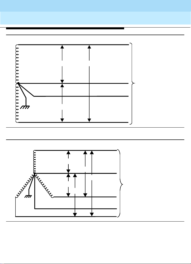
DEFINITY Enterprise Communications Server Release 8.2
System Description
555-233-200
Site Requirements
Cabinet Power Requirements
Phase A
120 240
Issue 1
April 2000
48
120
Figure 17. Single-Phase, 120/240 VAC, 60 Hz Source
Phase A
120
208
Neutral
208
120
120
Phase B
Ground
Phase C
Figure 18. Three-Phase, 120/208 VAC, 60 Hz Source
Neutral
Ground
Phase B
To equipment room
AC load center
To equipment room
AC load center
widf3phs LJK 071597
widf1phs LJK072298
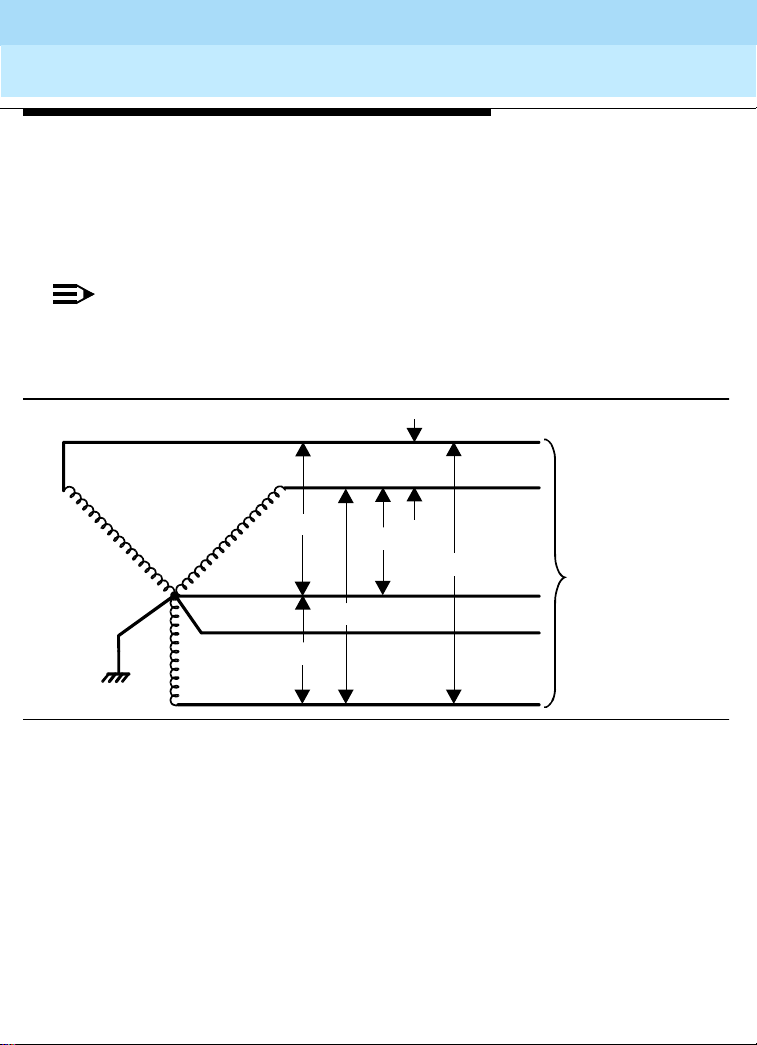
DEFINITY Enterprise Communications Server Release 8.2
System Description
555-233-200
Issue 1
April 2000
Site Requirements
Cabinet Power Requirements
50 Hz Power Sources in R8 Systems
Either of the following power sources can supply 50-Hz power to the AC- load in R7 and
later systems:
■ International 5-wire, Y, 220/380 VAC. See Figure 19.
■ International Delta, 3-wire, 220 or 240 VAC. See Figure 20.
NOTE:
The type of power for a Multi - Carrie r Ca bi net i s sh own on the c abi ne t’s rear door,
a Single-Carrier Cabinet is shown on the cabinet’s rear cover, and a Compact
Modular Cabinet is shown on the right door.
Phase A
49
220 V
220 V
380 V
220 V
380 V
Phase B
380 V
Neutral
Ground
Phase C
Figure 19. International, Three Phase, 220/380 VAC, 50-Hz Source
To equipment room
AC load center
widf4wir LJK 071497

DEFINITY Enterprise Communications Server Release 8.2
System Description
555-233-200
Site Requirements
Cabinet Power Requirements
Phase A
220 V
Issue 1
April 2000
50
220/240 V
Phase B
To equipment
room AC load
center
220 V
Phase C
widf3wir LJK071497
Figure 20. International Delta, 220 or 240 VAC, 50-Hz Source
Table 9 lists the AC-power sources that can supply power to an AC- load in a cabinet. A
NEMA receptacle (or equiv ale nt) c onn ec ts to the wires from the un it. The AC power cord
from the power input of each unit plugs into a receptacle.
Contact your Lucent Technologies representative for the list number of each power
source application.

DEFINITY Enterprise Communications Server Release 8.2
System Description
Site Requirements
555-233-200
Cabinet Power Requirements
Table 9. Cabinet AC Power Sources
Cabinet Style and Power
Distribution Unit Power Sources Power Input Receptacles
Compact Modular
Cabinet AC power
supply
(650A)
Multi-Carrier Cabinet
AC power distribution
(J58890CE-1 and
J58890CE-2)
Multi-Carrier Cabinet
AC Power distribution
(J58890CH-1)
Single-Carrier Cabinet
AC power supply
(1217A)
Single phase 120 VAC
with neutral
Single phase 240 VAC
with neutral
Single phase 120 VAC
with neutral
Single phase 240 VAC
with neutral, or single
phase of 3-phase, 208
VAC with neutral
Single phase 176-264
VAC
Single phase 120 VAC
with neutral
Single phase of 220 VAC
or
Single phase of 240 VAC
120 VAC, 60 Hz NEMA 5-15R
240 VAC, 50 Hz IEC 320
Japan installs use country
specific receptacles for 100 and
200 VAC, 50/60 Hz
120 VAC, 60 Hz NEMA
5-50R
208/240 VAC, 60 Hz NEMA
L14-30R
200-240 Volts, 50-60 Hz NEMA
L6-30R. Installati ons outside the
United States require a
receptacle suitable f or use in the
country of installation.
120 VAC, 60 Hz NEMA 5-20R or
5-15R
220/240 VAC at country-s pecific
receptacle
Issue 1
April 2000
51
Continued on n e xt page

DEFINITY Enterprise Communications Server Release 8.2
System Description
555-233-200
Issue 1
April 2000
Site Requirements
Cabinet Power Requirements
DC Power
DC-powered cabinets containing a J58890CF power distribution unit require a -42.5 to
-56 VDC source at up to 75 A. R efe r to " Mu lti -Carrier Cabi net Power system" on page 43.
Refer to ‘‘Single-Carrier Cabinet Power Systems’’ on page 65 for DC-power information.
For DEFINITY Wireless Business System power requirements, refer to Appendix A.
AC and DC Load Center Circuit Breakers
The circuit breaker sizes for all AC- and DC-powered cabinets are listed in Table 10 and
Table 11.
Table 10. Circuit Breakers for AC-Powered Cabinets
Cabinet Type Circuit Breaker Size
Compact Modular Cabinet (120 VAC) 60 Hz 15 A
Compact Modular Cabinet (240 VAC) 50 Hz 10 A
Multi-Carrier Cabinet (120 VAC) 60 Hz 50 A
Multi-Carrier Cabinet (208 VAC) 60 Hz 30 A
Multi-Carrier Cabinet (240 VAC) 60 Hz 30 A
Multi-Carrier Cabinet (200-240 VAC) 50-60 Hz 30 A
Single-Carrier Cabinet (120 VAC) 15 or 20 A
Auxiliary cabinet (120 VAC) 20 A
52
.
Table 11. Circuit Breakers for DC-Powered Cabinets
Cabinet Type (–48 VDC) Circuit Breaker Size
Multi-Carrier Cabinet 75 A
Single-Carrier Cabinet 25 A
Auxiliary cabinet 20 A

DEFINITY Enterprise Communications Server Release 8.2
System Description
Site Requirements
555-233-200
Issue 1
April 2000
Cabinet Power Requirements
Multi-Carrier Cabinet Power System
These power systems consist of an AC- or DC-power distribution unit in the bottom of
each cabinet and cabling to distribute output voltages to power unit circuit packs in the
carriers. These power systems also consist of power-converter circuit packs in the
carriers supplying DC- power to the circuit pack slots. Chapter 3 describes the
AC-version 631DA1 and 63 1DB1 power u nits an d the D C-versi on 644A, 6 45B, and 649A
power converters.
Table 12 lists the input and output voltages of power unit circuit packs in the carriers of
Multi-Carrier Cabinet s.
Table 12. Power Units in Multi-Carrier Cabinets
Model Inputs Outputs
120 VAC 144VDC -48 VDC +5 VDC
60 A
AC 631DA1 yes yes no yes no no
AC 631DB1 yes yes no no yes yes
DC 644A no no yes yes no no
DC 645B no no yes no yes yes
DC 649A no no yes yes yes 10 A
–5 VDC
6 A
–48 VDC
8 A
53
AC and DC Power Distribution
A typical AC-power distribution unit for a Multi-Carrier Cabinet contains the circuit
breakers, ring generator, optional batteries, and optional battery charger. The power
distribution cables carry 120 VAC during normal operation and 144 VDC from optional
batteries if AC power fails. Another cable connects 120 VAC to the battery charger.
DC-powered cabinets require a -42.5 to -56 VDC source at up to 75 A.

DEFINITY Enterprise Communications Server Release 8.2
7
System Description
555-233-200
Issue 1
April 2000
Site Requirements
Cabinet Power Requirements
AC Power Distribution
Figure 21 shows an AC Power Distrib ution Unit an d Battery Charg er (J58890 CE-2 List 15
or later). This unit sits at the bottom of some Multi-Carrier Cabinets.
Circuit
breakers
631DB
power unit
Ring generator
Ring
generator
Figure 21. AC Power Distribution Unit (J58890CE-2) (Front)
fuse
psdfacpd RPY 05309
54
The AC-Power Distribution Unit contains the following additional components not shown
in the figure:
■ Electromagnetic Interference (EMI) filter
■ AC input fuse
■ 5 circuit breakers (1 for each carrier)
■ 20-amp fuses
■ Signal connector
■ -48 VDC fan power
The optional battery c harger (Lis t 11) sits at the bottom of some mul ticarrier cab inets. See
Figure 22.

DEFINITY Enterprise Communications Server Release 8.2
7
System Description
555-233-200
April 2000
Site Requirements
Cabinet Power Requirements
Batte ry
charger
Batte rie s
psdfbatt RPY 05309
Figure 22. Battery Charger (Optional Part of J58890CE-2) (Front)
The battery charger is used only without an Uninterruptible Power Supply (UPS). The
charger contains:
■ Three 48-VDC batteries for backup power to the cabinet
■ A DC-power relay to switch the batteries into the power circuit if a main power
failure is detected
Issue 1
55
Circuit Breaker
The circuit break er prote cts th e AC inp ut power to the cab inet and serves as th e main AC
input disconnect switch. The circuit breaker has 2 poles for 120 VAC or 3 poles for
208/240 VAC. If a problem develops, the circuit breaker automatically trips (opens) and
removes the AC power input.
48-VDC Batteries
The 3 series-connected 48-VDC batteries produce a nominal 144 VDC, fused at 20 A.
The batteries trickle-charge from the battery charger.
Battery Charger
When AC power restores after an outage, the battery charger converts a 120 VAC input
to a DC voltage that recharges the batteries (usually within 24 hours).
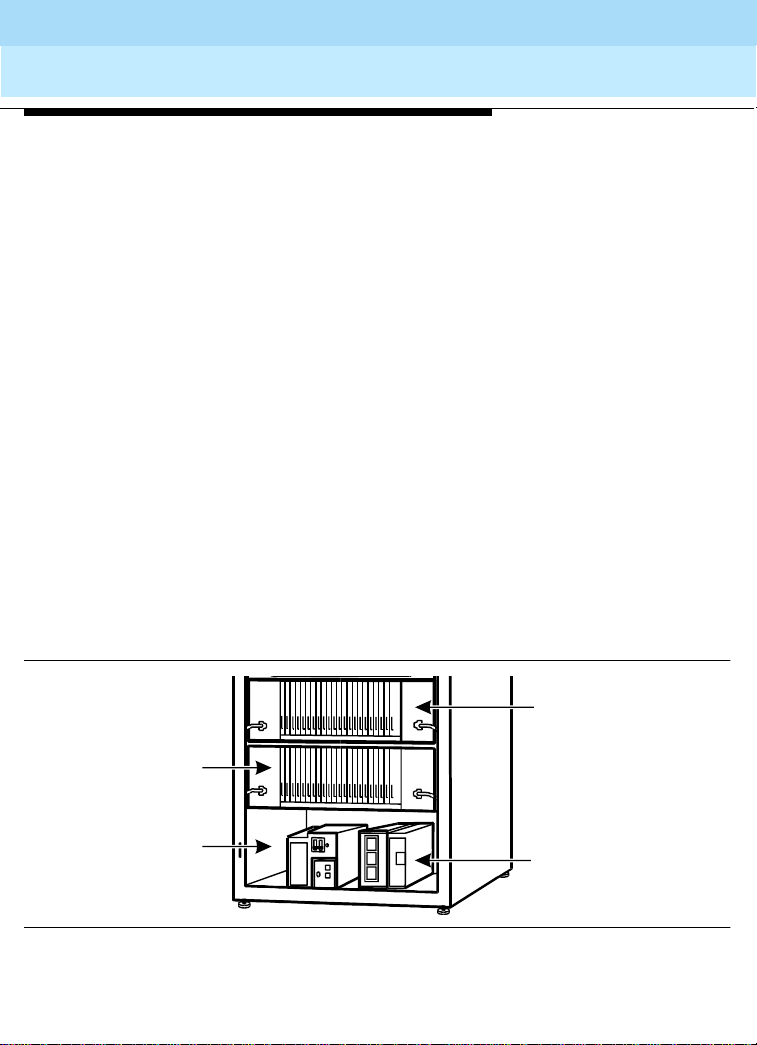
DEFINITY Enterprise Communications Server Release 8.2
System Description
555-233-200
Issue 1
April 2000
Site Requirements
Cabinet Power Requirements
DC Power Relay
This relay disconnects the batteries from a system when using AC power. The relay also
disconnects the batteries if power fails for more than 10 minutes in a standard reliability
system, 5 minutes in high and critical reli abi lity systems, and 10 mi nu tes in an exp ans ion
port network (EPN). This protects the batteries from over-discharging.
Electromagnetic Interference (EMI) Filters
The EMI filters suppress noise voltage on the AC input line to the unit.
Ring Generator
The ring generator converts the -48 VDC input to a 67 VAC to 100 VAC, 20 Hz or 25 Hz
ringing voltage. The analog line circuit packs use this AC voltage output to ring voice
terminals. The AC outputs route from the ring generator to port carriers, expansion
control carriers, and control carriers.
Fuses
20-Amp fuses protect the power on each cable going from the AC- Power Distribution
Unit to power converters in the carriers.
Figure 23 shows AC power distribution in some Multi-Carrier Cabinets. The DC-power
distribution cables are on both sid es of the cab inet. Thes e cables s upply powe r to each of
the carriers. The opt ional battery charg er is a t the ri ght si de of th e Power D istribut ion Unit.
56
"E"Position
Carrier
Power
3
distribution
unit
lcdfacpd RPY053097
Figure 23. AC Power Distribution in Multi-Carrier Cabinets
"D"position
carrier
Battery
charger
(optional)
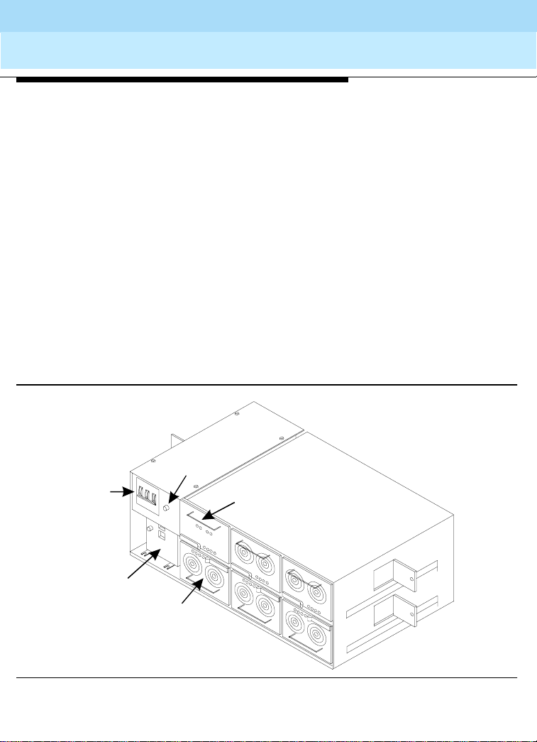
DEFINITY Enterprise Communications Server Release 8.2
System Description
555-233-200
Issue 1
April 2000
Site Requirements
Cabinet Power Requirements
Power Backup
If AC power fails, three 48-VDC batteries power the system for 10 seconds in a PPN
cabinet, for 15 seconds in an EPN cabinet, and for 10 minutes in the control carrier in a
standard reliability system. The batteries also supply system power for 5 minutes in the
control carrier in high and critical reliability systems, and for 10 minutes in the expansion
control carrier in the A
position of an EPN cabinet (R7r and later only).
Uninterruptible Power Supply (UPS)
An external, Uninterruptible Power Supply (UPS) provides a longer backup time than
holdover batteries (holdover times vary from less than 10 minutes to up to 8 hours) and
can replace the batteries and battery charger. The unit connects from the AC-power
source to a cabinet’s AC-power cord. If AC power fails, the unit supplies its own AC
power to the cabinet.
AC Power Distribution Unit (J58890CH-1)
Figure 24 shows a typical AC Power Distribution Unit used in some Multi-Carrier
Cabinets. The unit sits at the bottom of the cabinet.
57
Ring generator
fuse
Circuit
breakers
Ring
generator
Rectifier
modules
Batte ry
interface unit
psdfacp1RPY 053097
Figure 24. AC Power Distribution Unit (J58890CH-1) (Front)

DEFINITY Enterprise Communications Server Release 8.2
7
System Description
555-233-200
Issue 1
April 2000
Site Requirements
Cabinet Power Requirements
Power Backup
There are 2 types of battery assemblies used for power backup: small and large. The
small batteries are t ypicall y locate d at the c enter rear of a Mult i-Carrier Cabin et. The la rge
batteries are typically located inside the battery cabinet.
Small Batteries
The small battery is an 8 AH (Amp-hour) battery fused for short circuit protection and is
charged by the J58890CH-1. The batteries also contain a thermal sensor that changes
the charging voltage depending on battery temperature. See Figure 25.
The small batteries provide short-term battery holdover. If AC power fails, 48 VDC
batteries power the system for 10 seconds in a PPN cabinet, for 15 seconds in an EPN
cabinet, and for 10 minutes in the control carrier in a standard reliability system. The
batteries also prov ide sy stem powe r for 5 mi nutes in the c ontrol carrier in h igh an d criti cal
reliability systems , and for 10 m in utes in th e ex pa nsi on con trol carri er in the A po si tion of
an EPN cabinet (R7r and later only).
58
Batte ry
connector
Figure 25. Small Battery Assembly
psdfbatw RPY06179

DEFINITY Enterprise Communications Server Release 8.2
System Description
555-233-200
Issue 1
April 2000
Site Requirements
Cabinet Power Requirements
Large Batteries
The large batteries can supply holdover times of 2 to 8 hours, depending on the number
of batteries. When using large battery holdover, 1 battery cabinet is required per system.
The 24-cell battery cabinet must have float voltage of 54.2 VDC. The 23-cell battery
cabinet must have a float voltage of 51.75 VDC. The batteries are circuit breaker
protected and are charged by the J58890CH-1.
The batteries also contain a thermal sensor that changes the charging voltage,
depending on the battery temperature. The batteries provide extended holdover. Battery
holdover and recharg e ti mes f or a typ ical 2500-Watt load are shown in Table 13. A typical
large battery cabinet, (200 A) is shown Figure 26.
Table 13. Battery Holdover and Recharge Times
Cabinet Type Holdover Time Recharge Time
100 A 2 hours 7 hours
200 A 4 hours 13 hours
300 A 6 hours 20 hours
400 A 8 hours 26 hours
59
Large battery
cabinets
Circuit
breaker
psdflbc1RPY 053097
Figure 26. Typical Large Battery Cabinets

DEFINITY Enterprise Communications Server Release 8.2
l
7
System Description
555-233-200
April 2000
Site Requirements
Cabinet Power Requirements
DC Power Distribution
The typical distribution system has a DC power converter and cables to provide the
power to the system circuit packs.
DC Power Distribution Unit (J58890CF-2)
Figure 27 shows a Power Distribution Unit in some DC-powered Multi-Carrier Cabinets.
The unit sits at the bottom of the cabinet and contains the ring generator, 20-amp circuit
breakers, terminal blocks, and system fan power.
DC power
distribution
unit
Issue 1
60
Circuit
breakers
Figure 27. DC Power Distribution Unit (J58890CF-2) (Front)
Termina
block
Ring
generator
psdfdpdu R P Y05309

DEFINITY Enterprise Communications Server Release 8.2
System Description
555-233-200
Issue 1
April 2000
Site Requirements
Cabinet Power Requirements
Ground Isolation
Each peripheral connecting to a DEFINITY System, via the Asynchronous Electronic
Industries Association (EIA) RS-232 interface, requires either a 105C, a 105D or a 116A
Isolator Interface. The interface isolates ground between the system and external
adjuncts.
The Isolator Interfac e is behind a PPN contro l carrier or behind an E PN expansion c ontrol
carrier. The 105C, 105D, or the 116A installs at the RS-232 interface between the
peripheral equipment and the interface connector.
Figure 28 shows the power distribution in some Multi-Carrier Cabinets with short term
battery holdover (small battery). In R7r and later systems, the power distribution cables
are on the right hand side of the cabinet only. This is because the 649A DC power
converter circuit pack replaces 2 power converters at either end of each carrier. Switch
node (SN) carriers require two 649As and 2 cables.
61
Port carrier
control carrier
649A DC power
converter circuit pack
distribution
Port or
Fan unit
Power
unit
1
4
Figure 28. Power Distribution in Multicarrier Cabinets
649A DC
power converter
circuit pack
Small battery
(Inside cabinet)
Control
carrier
Port or switch
node carrier
Port or switch
node carrier
lcdfpdu1LJK 071497

DEFINITY Enterprise Communications Server Release 8.2
System Description
555-233-200
Issue 1
April 2000
Site Requirements
Cabinet Power Requirements
Figure 29 shows the DC-power dis trib uti on i n s om e Mu lti -Carri er C ab ine ts wi th ex te nded
battery backup (large batteries). In R7r and later systems, the power distribution cables
are on the right side of the cabinet only. This is because the 649A DC power converter
circuit pack replaces 2 power converters at either end of each carrier. Switch node (SN)
carriers require two 649As and two cables.
649A DC
power converter
circuit pack
Large battery
Control
carrier
649A DC power
converter
circuit pack
Circuit
breaker
cabinets
62
Power
distribution
unit
Switch node
carrier
lcdfpdu2 LJK 110797
Figure 29. DC Power Distribution in Multicarrier Cabinets
DC Power Converter (649A)
The 649A converts the –48 VDC from the Power Distribution Unit to outputs of –48 VDC
at 10 A, +5 VDC at 60 A, and –5 VDC at 6 A. These outputs distribute power to circuit
pack slots in the carriers.
AC and DC Grounding
Approved Grounds
An approved ground is th e closest acceptable medi um for grounding the building
entrance protector, the entrance cable shield, or single-point ground of the system.
If more than one type of approv ed grou nd is av ailab le on the premis es, bon d the grou nds
together as specified in Section 250-81 of the National Electrical Code, or the applicable
electrical code in the country where the equipment is installed.

DEFINITY Enterprise Communications Server Release 8.2
System Description
555-233-200
Issue 1
April 2000
Site Requirements
Cabinet Power Requirements
Protective Grounds
Grounded Building Steel — The m etal f rame of the building where it is grounded b y one
of the following: acceptable metallic water pipe, concrete encased ground, or a ground
ring.
Acceptable Water Pipe — Underground water pipe, at least 1/2 inch
(1.3 cm) in diameter, needs to be in direct contact with the earth for at least 10 feet (3
meters). The pipe must be electrically continuous (or made electrically continuous by
bonding around insulated joints, plastic pipe, or plastic water meters), to the point where
the protector ground wire is connected.
A metallic underground water pipe must be supplemented by the metal frame of the
building, a concrete encased ground, or a ground ring.
If these grounds are no t available, the water pip e ground can be supp lem en ted by o ne of
the following types of grounds:
■ Other local metal underground systems or structures — Local underground
structures such as tanks and piping systems
■ Rod and pipe electrodes — A 5/8 inch (1.6 cm) solid rod or 3/4 inch (1.9 cm)
conduit or pipe electrode driven to a minimum depth of 8 feet (2.5 meters)
■ Plate electrodes — Mus t ha ve a m in imum of 2 sq uare feet (0.18 square meters) of
metallic surface exposed to the exterior soil
Concrete Encased Ground — A n el ec trode en cas ed by at l eas t 2 i n. (5 cm ) of co ncr ete
and located within and near the bottom of a concrete foundation or footing in direct
contact with the earth. The electrode must be at least 20 feet (6 meters) of one or more
steel reinforcing bars or rods 1/2 inch (1.3 cm) in diameter, or at least 20 feet (6 meters)
of bare, solid copper, 4 AWG (26 mm
2
) wire.
Ground Ring — A buried ground that encircles a building or structure at a depth of at
least 2.5 feet (0.8 meter) below the earth's surface. The ground ring must be at least 20
feet (6 meters) of 2AWG (35 mm2), bare, copper wire.
63

DEFINITY Enterprise Communications Server Release 8.2
System Description
555-233-200
Site Requirements
Cabinet Power Requirements
Approved Floor Grounds
Issue 1
April 2000
64
!
!
WARNING:
If the approved ground or ap prov ed floo r gro und can onl y b e ac ce ss ed i ns ide a
dedicated power equipment room, then connections to this ground should be
made by a licensed electrician.
Approved floor grounds are those grounds on each floor of a high-rise building suitable
for connection to the ground terminal in the riser closet and to the cabinet equipment
single-point ground terminal. Approved floor grounds may include the following:
■ Building steel
■ The grounding conductor for the secondary side of the power transformer feeding
the floor
■ Metallic water pipes
■ Power feed metallic conduit supplying panel boards on the floor
■ A point specifically provided in the building design for grounding
NOTE:
Electrically connect all protective grounds together to form a single grounding
electrode system.
Coupled Bonding Conductor
When using Coupled Bonding Conductor (CBC) grounding in an AC- powered cabinet,
maintain a minimum 1 ft. (0.3 m) spacing between the CBC and other power and ground
leads.
In AC-powered systems, locate the system single-point ground terminal block on the AC
load or AC protector cabinet.

DEFINITY Enterprise Communications Server Release 8.2
System Description
555-233-200
Issue 1
April 2000
Site Requirements
Cabinet Power Requirements
Single-Carrier Cabinet Power Systems
Each Single-Carrier Cabinet has 1 AC or 1 DC power supply that distributes DC-power
and AC ringing voltage to the circuit pack slots in the cabinet.
AC Power Supply (1217A)
In an AC-powered cabinet, a single, plug-i n, multi-out put AC power supp ly is in the power
supply slot. A power cor d, with a 3-pr ong pl ug on one en d and an app lianc e conn ector on
the other end, connects the supply to a dedicated AC power source.
The 1217A is a global power unit for Single-Carrier Cabinets. It has a wide input voltage
operating range of 90 to 264 VAC and a 50/60 Hz autoranging input, multi-output power
supply that provides regu late d D C output. The 1217A also has a s el ect abl e 20 /25 Hz AC
ringer .
The inputs to the power supply can be (depending on list version):
■ 120 VAC, 60-Hz, 15-Amp to 20-Amp; 3 wires in the power cord: 1 hot wire, 1
neutral wire, and 1 ground wire
■ 220 VAC or 240 VAC, 50-Hz, 10-Amp; 3 wires in the power cord: 1 hot wire, 1
neutral wire, and 1 ground wire
The AC power supply produces the following DC outputs: +5 VDC, –5 VDC, –48 VDC,
+12 VDC, and a b attery- charging voltage. The DC o utputs di stribute power on the cab inet
backplane t o the circuit pack slots. Additionally, the -48 VDC output current capacity has
been increased from 6.85 amps to 8.25 amps. A 50 amp load inrush requirement has
been added to the -48 VDC output
A holdover circuit in the power supply allows a system to operate normally during AC
power interruptions. If AC in put power fails, re serve ba tteries sup ply power to the m emory
and processor circuit packs and fans for 2 minutes. All port circuit packs are inactive
during this time. The power supply contains a battery charger to charge the holdover
batteries.
65

DEFINITY Enterprise Communications Server Release 8.2
System Description
Site Requirements
555-233-200
Issue 1
April 2000
Cabinet Power Requirements
DC Power Supply (676C)
In a DC-powered Single-Carrier Cabinet, a single, plug-in multi-output DC power suppl y
is in the power supply slots.
The 676C DC power su pply has a wide input vo ltage ope rating rang e of -42 to -60 VDC at
up to 22A. The 676C produces the following outputs: +5 .1 VDC at 0 to 55A, -5. 1 VDC at 0
to 5.5A, +12 VDC at 0 to 2A (surge to 2.8A for 350 ms), -48 VDC at 0 to 8.25A. The
outputs distribute power on the cabinet backplane to the slots for the circuit packs. The
AC ringing voltage output value and frequency depend on the country of use. The power
supply has circuit breakers and EMI filtering.
DC Power Distribution Unit (J58890CG)
The J58890CG is used wit h Single-Carrier Cabinets. Indiv idual DC outpu t connectors can
power up to 4 Single-Carri er Cab inets. Eac h outpu t conne ctor is separa tel y fuse d at 25 A
(fuses are inside the unit). The input to the DC distribution unit is from the DC power
cabinet.
The J58890CG is required when the distance between the DC power cabinet and the
cabinet stack is greater than 30 feet (9 m).
Enhanced DC Rectifier Cabinet (J58890R)
The J58890R is used with Single-Carrier Cabinets. Each rectifier assembly in the DC
rectifier cabinet can suppl y up to 50 A of D C current. A mi nimum of tw o rectifi ers instal l in
each DC cabinet to su ppl y a to tal of 100 A. A third rec tifier assembly is us ed as a ba ck up
only.
Each Single-Carrier Ca bin et can dra w up to 1 5 A. U p to 3 DC cab in ets ca n b e s tac ke d to
supply power to single-carrier cabi nets stacks.
Each output connector is separately fused at 25 A (fuses are inside each DC rectifier
assembly).
66
NOTE:
A J58890CG DC Power Distribution Unit is required if the distance between the
DC cabinet and the cabinet stack is greater than 30 feet (9 m).

DEFINITY Enterprise Communications Server Release 8.2
System Description
555-233-200
Issue 1
April 2000
Site Requirements
Cabinet Power Requirements
Compact Modular Cabinet (CMC)
AC Power Supply (650A)
In the Compact Modular Cabinet, a power cord, with a 3-prong plug on one end and an
appliance connector on the other end, connects the supply to a dedicated AC power
source. The power supply is a global power factor corrected AC/DC converter providing
multiple DC out puts a nd AC rin g outp uts. It is au to rang ing 85 to 264 VAC, 47 to 63 Hz, at
330 Watts, 4.5 A (100-120 VAC) or 2.3 A (200-240 VAC) at 500 VA.
The inputs to the power supply can be (depending on list version):
■ 120 VAC, 50-Hz to 60-Hz, 6-Amp; 3 wires in the power cord: 1 hot wire, 1 neutral
wire, and 1 ground wire
■ 220 V AC or 2 40 VAC, 50-Hz to 60-Hz, 3-Amp; 3 wires in the p ower cord: 1 hot w ire,
1 neutral wire, and 1 ground wire
The AC power supply produces the following outputs: +5 VDC, –5 VDC, and –48 VDC.
The outputs distribute power on the cabinet backplane to the circuit pack slots. The AC
ringing voltage outp ut va lue and freq uen cy dep end on the c oun try of us e. Th e 650 A als o
supplies power for neon message-waiting lamps (150 VDC). The power supply has EMI
filtering.
Compact Modular Cabinet (CMC)
Uninterruptible Power Supply (UPS)
The UPS provides surge protection for all connected cabinets.
1. Connect the UPS to an electrical outlet capable of handling the power
requirements of all cabinets. To calculate the number of amps drawn, use the
following formulas.
a. 100-200 VAC, multiply 3.5 amps times the number of cabinets.
b. 200-240 VAC, multiply 1.8 amps times the number of cabinets.
2. Cabinet A (control carrier) is always connected to an
electrical outlet on the UPS.
unswitched
or
always on
67

DEFINITY Enterprise Communications Server Release 8.2
System Description
Site Requirements
555-233-200
Issue 1
April 2000
Cabinet Cooling Fans
Cabinet Cooling Fans
Compact Modular Cabinet (CMC) Fan Unit
Two variable-speed fans are at the bottom of the cabinet. They receive +8 to +14 VDC
from the power supply. An air filter, which can be removed and cleaned or replaced, is
located above the fans. Air flows from the outside, into the bottom of the cabinet, around
the circuit packs, and out through the top of the cabinet.
o
If the cabinet temperature reaches 158
supply shuts the system down and invokes the emergency transfer.
Multi-Carrier Cabinet Fans
A fan unit consisting of 6 fans, mounts near the center of the cabinet. The 3 front fans
blow up and the 3 rear fans blow down. A removable air filter is provided above and
below each fan unit. Four sensors monitor the cabinet temperature; 3 sensors are inside
the cabinet top and 1 sensor is inside the cabinet bottom. One of the top sensors affects
the speed of the front fans and the bottom sensor affects the speed of the rear fans. A
speed control and thermal ala rm circu it in each fan monitors the sen sor s. When a sensor
indicates a change in cabinet temperature, the circuit in a fan changes that fan’s speed
accordingly.
A power cable from th e Pow er Dis tributi on Uni t con nects -4 8 VD C to e ach f an, +5 VDC to
the speed control and thermal alarm circuit in each fan, and temperature sensor signals
to the equivalent circuit in each fan. One pair of wires routes to each fan circuit. Alarm
signals also route to the equivalent circuit in each fan. One pair of wires routes to each
fan circuit.
A minor alarm is sent to the processor circuit pack in the PPN cabinet and the
maintenance circuit pack in an EPN cabinet if any fan’s speed drops below minimum. A
minor alarm occurs if a fan has stopped due to loss of -48 VDC. A major alarm is sent by
one of the cabinet top therm al sensor s if the exha ust temper ature reache s 149
Another cabinet top sensor senses if the exhaust temperature reaches 158
so, the system shuts down and the Emergency Transfer is invoked.
F (70o C), the temperature sensor in the pow er
o
F (65oC).
o
F (70 oC). If
68

DEFINITY Enterprise Communications Server Release 8.2
System Description
555-233-200
Issue 1
April 2000
Site Requirements
System Protection
Single-Carrier Cabinet Fan Unit
Four constant-speed fans at the top rear of the cabinet receive -48 VDC from the
backplane. An air fi lte r is lo ca ted bel ow th e f an uni t. Ai r flows down through th e fi lte r ov er
the circuit packs. The filter is removable and is cleaned or replaced when necessary.
o
If the cabinet temperature reaches 158
F (70o C), the temperature sensor in the power
supply causes the system to shut down and invokes the Emergency Transfer.
System Protection
Protections are established to keep the DEFINITY System active and on line. The
following 4 types of system prot ect ion are provi ded :
■ Overvoltage
■ Sneak current
■ Lightning
■ Earthquake
Overvoltage Protection
69
Protection from hazardous voltages and currents is required for all off-premises
(out-of-building) trunks, lines, and terminal installations. Both over-voltage protection
(lightning, power induction, and so forth) and sneak current protection are required. The
following devices protect the system from overvoltages:
■ Analog trunks use the 507B Sneak Protector. Over-voltage protection is normally
provided by the local telephone company.
■ Analog voice and 2-wire DCP terminals can use 1 of the following (or equivalent)
types of combined overvoltage and sneak current protection:
— Carbon block with heat coil for UL code 4B1C
— Gas tube with heat coil for UL code 4B1E-W
— Solid state with heat coil for UL code 4C1S
■ DCP and ISDN-BRI terminals use the solid state 4C3S-75 with heat coil protector,
or equivalent.
■ DS1/E1/T1 circuits require isolation from exposed facilities. A CSU (T1), LIU (E1),
or other equipment provides this isolation.

DEFINITY Enterprise Communications Server Release 8.2
System Description
Site Requirements
555-233-200
Issue 1
April 2000
System Protection
Sneak Current Protection
Sneak current protection uses fuses to protect building wiring between the network
interface and trunk circuits when exposed to extraneous power. The fuses also protect
the circuit packs.
All incoming and outgoing trunks and off-premises station lines pass through the sneak
fuses. 507B Sneak fuse panels install on the system side of the network interface.
Sneak current protectors must be either UL listed/CSA certified or must comply with local
safety standards. Sn eak current pro tectors m ust have a maximu m rating of 350 mA and a
minimum voltage rating of 600V, or as required by local regulations.
Lightning Protection
A Coupled Bonding Conductor (CBC) in the cabinet ground wiring protects the system
from lightning. The CBC runs adjacent to wires in a cable and causes mutual coupling
between itself and the wires. The mutual coupling reduces the voltage difference
between ground and the DEFINITY ECS.
When using a CBC, be sure that it connects to telecommunication cable that is firmly
connected to an approved ground. In multipl e-story buildings , be sure to connect th e CBC
to an appr oved ground at each floor.
2
The CBC can be a 10 AWG (5.3 mm
surrounding wires within a cable, or 6 unused pairs of wire within a cable, twisted and
soldered together. The CBC connects from the cabinet single-point ground bar in an
AC-powered cabinet or the gr ound di scharge b ar in a DC-po wered cabine t to the term inal
bar at the cross-connect field.
When there is an Auxiliary cabinet, a 6 AWG (13.3 mm
system cabinet single-point ground block to the Auxiliary cabinet ground block. The
ground wire routes as closely as poss ible to the cables that conne ct the system cab inet to
the Auxiliary cabinet.
If equipment is not present in the Auxiliary cabinet, plug the power supply for this
equipment into 1 of the 2 convenience outlets on the rear of the Multi-Carrier Cabinet, to
preserve ground integrity. The convenience outlet is fused at 5 Amps. A dedicated
maintenance terminal plugs into the other convenience outlet.
/2.6 mm) ground wire, a continuous cable sheath
2
/4.1 mm) wire connects the
70

DEFINITY Enterprise Communications Server Release 8.2
System Description
Site Requirements
System Protection
555-233-200
Issue 1
April 2000
Earthquake Protection
For earthquake o r disa ster b rac ing, the ca binets bol t to th e flo or. Other areas may require
additional bracing. Contact your Lucent Technologies representative for earthquake
requirements at the location of the system installation.
71

DEFINITY Enterprise Communications Server Release 8.2
System Description
Site Requirements
555-233-200
System Protection
Issue 1
April 2000
72

DEFINITY Enterprise Communications Server Release 8.2
System Description
Cabinets, Carriers, and Circuit Packs
Cabinets
555-233-200
Issue 1
April 2000
3 — Cabinets, Carriers, and Circuit Packs
This section describes the cabinets, carriers, and circuit packs, their functions, physical
specifications, and interconnections in DEFINITY ECS R8. It also describes minimum
cabinet and carrier configurations relative to interconnection and system-duplication
options.
NOTE:
To determine required types and numbers of cabinets, carriers, circuit packs, or
adjuncts before installation, contact your Lucent Technologies representative.
Cabinets
This section describe s the auxiliary, Processor Port Network (PPN), Expansion Port
Network (EPN), and AC-power cabinets.
A Multi-Carrier Cabinet (MCC) can be used as a PPN cabinet and/or an EPN cabinet.
Doors on the front and rear of the MCC protect the internal equipment and allow easy
access to the circu it pac ks. Each c abine t conta ins cas ters. Le velin g feet k eep th e cabi net
from rolling. Each corner of a cabinet can bolt to the floor, if required. See Figure 30.
The DEFINITY csi model uses the Compact Modular Cabinet (CMC).
The DEFINITY si model uses the Single-Carrier Cabinet (SCC) or the MCC.
The DEFINITY r model uses the Multi-Carrier Cabinet for the PPN and uses either the
MCC or the SCC for the EPNs.
73

DEFINITY Enterprise Communications Server Release 8.2
8
System Description
555-233-200
Cabinets, Carriers, and Circuit Packs
Cabinets
"C" po sition
carrier
"A" pos ition
carrier
"F" pos ition
2
fan unit
"E" pos ition
carrier
"B" position
carrier
"D " positio n
carrier
Issue 1
April 2000
74
Power
distribution
3
unit
lcdfmc03 EWS 09289
Figure 30. Typical MCC Layout
AUX Connector Capacity
The AUX (auxiliary) connector is on the rear of the control carrier. Up to 3 attendant
consoles or teleph one adjun cts can be powered b y the AUX connecto r in the A positio n in
the MCC and the SCC cabinets. Only 1 attendant console connects to the R8csi
cabinets.
Up to 3 emergency transfer panels can be powered by the AUX connector in the A
position in DEFINITY c abine ts. On ly 1 em ergenc y trans fer pan el con nects to csi cabin ets.

DEFINITY Enterprise Communications Server Release 8.2
System Description
555-233-200
April 2000
Cabinets, Carriers, and Circuit Packs
Cabinets
Auxiliary Cabinet (J58886N)
The Auxiliary Cabinet contains the hardware to install optional equipment. The cabinet
allows carrier, rack (width: 23 in.; 58.4 cm), and panel types of mounting. An Auxiliary
Cabinet contains the following:
■ Fuse panel (J58889AB) distributes –48 VDC to fused cabinet circuits
■ AC-power receptacle strip provides switched and non-switched 120 VAC
receptacles
■ DC connector block is required when the cabinet is powered by an external DC
source, or an AC to DC power supply that converts AC-power provided by the AC
power strip switched-outlet to the required DC-power
Processor Port Network Cabinet (J58890A)
A Processor Port Network (PPN) cabinet (see Figure 31) contains the following carriers:
■ Port carrier (J58890BB) — 1 to 4
■ Control carrier (J58890AH) in R7si and later — 1
■ Duplicated control carri er (J58890AJ ) R7si and l ater — 1 in high or critical rel iability
configurations
■ Processor carrier (J58890AP) inR7r and later — 1 in all systems, 2 in high
reliability and critical reliability systems
■ Switch Node (SN) (J58890SA) in R7r and later with a Center Stage Switch
(CSS) — 1 in standard and high reliability systems or 2 in critical reliability systems
■ In a R7r and later with ATM, the ATM interface card would be placed in a port
carrier.
Issue 1
75

DEFINITY Enterprise Communications Server Release 8.2
System Description
555-233-200
Cabinets, Carriers, and Circuit Packs
Cabinets
Port carrier
Port or control
carrier
Control carrier
Fan unit
Port or switch
node carrier
Port or switch
node carrier
Power
4
distribution unit
Issue 1
April 2000
76
Power unit
(typical)
lcdfpdu3 LJK 102899
Figure 31. Typical Multi-Carrier PPN Cabinet (J58890A)

DEFINITY Enterprise Communications Server Release 8.2
System Description
555-233-200
Cabinets, Carriers, and Circuit Packs
Cabinets
Expansion Port Network Cabinet (J58890A)
An Expansion Port Network (EPN) cabinet (Figure 32) contains the following carriers:
■ Port carrier (J58890BB) — 1 to 4
■ Expansion control carrier (J58890AF) — 1
■ SN Carrier (J58890SA) in CSS-conne cted R7r a nd later sy stems — 0, 1, or 2 when
required
Issue 1
April 2000
77
Port carrier
1
Expansion
control carrier
Port or switch
node carrier
Power
distribution
4
unit
Figure 32. Typical Multi-Carrier EPN Cabinet (J58890A)
Port carrier
Port or switch
node carrier
lcdfpdu4 LJK 081999

DEFINITY Enterprise Communications Server Release 8.2
System Description
555-233-200
Cabinets, Carriers, and Circuit Packs
Cabinets
Issue 1
April 2000
78
Expansion control
carrier (A)
Port carrier (E)
1
lcdfpdu5 LJK 092099
Figure 33. Dual EPN in an R7r or Later Multi-Carrier Cabinet
The above figure is for the configuration of a minimal Dual Expansion Port Network
cabinet for the r model. The A, B, and C carriers are intended for the first port network in
the cabinet. The D and E c arriers are intende d for the second po rt network in the c abinet.
The first carrier of a second Port Network in the cabinet must reside in carrier E. The E
carrier must be used when there is only one carrier in the second EPN in the cabinet.
When a cabinet has two Port Networks, carrier E must be used and populated first and
carrier D added and populated second.

DEFINITY Enterprise Communications Server Release 8.2
System Description
555-233-200
Cabinets, Carriers, and Circuit Packs
Carriers in MCCs
Carriers in MCCs
The following types of carriers can install in MCCs:
■ J58890AH Control Carrier (si model) (J58890AH Control Carrier (si model))
located only in the R7si or later PPN cabinet. Contains SPE circuit packs to
perform call processing, maintenance, and administration. These carriers also
contain port circuit pack slots.
■ Duplicated Control Carrier (si model) (J58890AJ) (optional), in R7si or later PPN
only. Contains duplicate SPE circuit packs to perform call processing,
maintenance, and administration identical to the Control Carrier. The Duplicated
Control Carriers also contain port circuit pack slots. Only R7si/r or later support
duplication (uses the R8r Control Carriers for duplication).
■ Processor Carrier (r model) (J58890AP), only in the R7r or later PPN cabinets.
Contains SPE circuit packs to perform call processing, maintenance, and
administration. These carriers do not con tain port circui t pack slot s. T wo J58 890AP
carriers are in the PPN for h igh an d critic al reli abili ty (dup licate proces sor) sy stems.
■ J58890BB Port Carrier (optional), located in the PPN and EPN cabinets. Contains
port, service, and tone/clock circuit packs.
■ Expansion Control Carrier (J58890AF), only in the EPN cabinets. Contains extra
port circuit packs, tone-clock, maintenance interface, and EI circuit packs.
■ Switch Node Carrier (SN) (J58890SA) (optional), in R7r o r late r, in the PPN cabinet
and/or EPN cabinets. Contains SNI circuit packs composing the CSS.
Issue 1
April 2000
79

DEFINITY Enterprise Communications Server Release 8.2
System Description
555-233-200
Issue 1
April 2000
Cabinets, Carriers, and Circuit Packs
Carriers in MCCs
Carrier Circuit-Pack Slots
There are 3 types of circuit pack slots in the carriers: Control, Port, and Service.
NOTE:
The purple-colored and white-colored circuit packs and slots are being replaced
by circuit packs and slots labeled with gray and white rectangles, respectively. A
label with a solid gray rectangle indicates a port slot/circuit pack. A label with an
outlined white rectangle indicates a control slot/circuit pack.
■ Port: colored purple or labeled with a gray rectangle and can accept any purple or
gray-labeled circuit pack
■ Control: colored white or labeled with an outlined white rectangle and can accept
only a circuit pack assigned to that slot
■ Service: colored purple or labeled with a gray rectangle; is a special type of circuit
pack that does not have an I/O connector
Each port slot attach es to a 50 -pin (2 5-pair) conne ctor on the carr ier’s rear pan el. A cable
attaches to each connector and routes to the cross-connect field. Each slot containing a
fiber optic interface circuit pack (EI or SNI) uses a fiber optic transceiver on the carrier’s
rear panel.
A current limiter board (CFY1B) plugs into the backplane of the control carrier located in
A
position only. The board supplies emergen cy tran sfer lo gic, c urrent-l imite d power, 5
the
VDC to trip the main circuit breaker in an over-temperature condition, and the ringing
transfer relay. Terminators on the backplane terminate each end of the processor
expansion bus.
The following apparatus blank faceplates (with widths) cover unused circuit pack slots in
the carriers to maintain proper air flow:
■ Z100A1 (0.75 inches/1.9 cm)
■ Z100C (0.5 inches/1.27 cm)
■ Z100D (0.25 inches/0.64 cm)
80
NOTE:
Throughout this section, the power units and circuit packs shown in the front
views of the carrie r s a re representative examples o nly. Actual, installed har dw are
may vary from that shown.
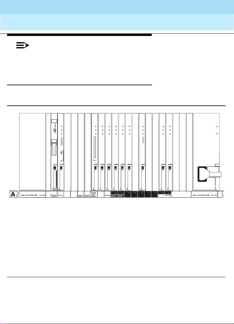
DEFINITY Enterprise Communications Server Release 8.2
System Description
555-233-200
Cabinets, Carriers, and Circuit Packs
Carriers in MCCs
NOTE:
In the following illustrations, a balanced ring generator (BRG) is shown below the
power unit slot in c ertain carriers . This means th e po wer unit slot c an inc lude a 50
Hz BRG when optioned for France.
J58890AH Control Carrier (si model)
A representative J58890AH control carrier is shown below.
Lucent
B
S
AUTO
P
A
E
OVERIDE
Z100A1
blanks
or
631DA1
103577450
ALARMS
MAJ
MIN
WRN
ACK
EMERTR
ON
AUTO
OFF
B
B
t
en
c
l
l
u
E
L
AC
F
R
a
a
TE
L IN
P
U
D
43
n
n
252
071
R
792
D
N
98
T
k
k
C
A
R
D
I
N
U
S
E
B
B
l
l
a
a
n
n
k
k
BBI
LINK
TRMT
RCV
B
B
l
l
a
a
n
n
k
k
Issue 1
April 2000
81
631DB1
or
649A
B
B
l
a
n
k
B
B
l
l
l
a
a
a
n
n
n
k
k
k
ccdfr8ah LJK 121399
T
Z
T
T
1
N
N
0
7
7
0
9
9
C
0
2
T
N
7
9
4
B
T
T
T
T
N
N
N
N
7
7
2
2
7
7
1
4
6
6
8
0
or
or
2
0
T
or
b
l
a
n
T
N
N
5
5
7
7
0
0
T
N
N
7
7
7
9
1
9
D
Z
T
1
N
0
7
0
5
D
5
or
B
b
l
a
n
k
k
Figure 34. J58890AH Control Carrier (si model) (J58890AH Control Carrier (si model))
(Front)

DEFINITY Enterprise Communications Server Release 8.2
System Description
555-233-200
Issue 1
April 2000
Cabinets, Carriers, and Circuit Packs
Carriers in MCCs
This carrier has dedicated white-colored circuit pack slots that always contain specific
control circuit packs. Dual-color slots may contain any port circuit pack or the designated
white circuit packs (such as an EI or power unit). AC or DC power units supply power to
the carrier. Table 14 describes the connectors on the rear of the control carrier.
NOTE:
The TN776 is not shipped in the R7si and later systems. It can remain in the
system if packet endpoints and the C-LAN (TN799) are not used.
.
Table 14. Control-Carrier Connectors
Connector Functio n
1 to 9 (A1 t o A9) 25-pair connectors provide interfaces between port circuit
packs and the cross-connect field or fiber transceiver
AUX (Auxiliary) Interface for alarms, attendant console power, emergency
power transfer panels, and an internal modem (for remote
maintenance)
Processor interface
(standard reliability
only)
Data communications
equipment
Terminal Connects a management terminal to the processor in
Duplication option
terminal
P1 Provides position indicator of the carrier, power to fans, and
P2 Provides control signals to the carrier
Connects directly to the PI circuit pack. Provides a BX.25
protocol interface fo r comm uni ca tion betw e en th e ci rcu it pa ck
and external DCE equipment.
Connects the processor to CDR equipment, a system printer,
or an external modem (for remote maintenance). This
connector can be used with any reliability option.
standard reliability systems. In critical reliability systems,
connects a terminal to the processor in its control carrier.
Used in high and critical reliability systems to connect an
administration terminal to the active processor from the
duplication interfac e slo t posi tio n
access to alarm and control circuits
82
Continued on next page

DEFINITY Enterprise Communications Server Release 8.2
System Description
555-233-200
Issue 1
April 2000
Cabinets, Carriers, and Circuit Packs
Carriers in MCCs
J58890AJ Duplicated Control Carrier
(si model)
The Duplicated Control Carrier (J58890AJ) has dedicated white circuit pack slots that
always contain specific control circuit packs. It can also be populated with port circuit
packs or dual-colored slots that may be populated with port circuit packs or designated
white circuit packs (such as an expansion Interface or power unit).
AC or DC power un its lo cated at ea ch end of th e Dupli cated Cont rol C arrier s upply power
to the carrier. See Figure 35 for a representative example. See Table 15 for the
Duplicated Control Carrier rear connector descriptions.
Lucent
B
S
AUTO
P
A
E
OVERIDE
Z100A1
blanks
or
631DA1
103577450
ALARMS
MAJ
B
MIN
WRN
ACK
l
EMERTR
a
ON
AUTO
n
OFF
k
B
t
cen
l
u
E
L
AC
F
R
E
T
a
IN
L
P
U
D
n
243
7125
0
R
792
N
8D
9
T
k
B
B
l
l
C
C
A
A
R
R
D
D
a
a
n
k
B
l
a
n
k
I
I
N
N
n
U
U
S
S
E
E
k
B
B
l
l
a
a
n
n
k
k
BBI
LINK
TRMT
RCV
631DB1
or
649A
B
B
l
a
n
k
B
l
l
a
a
n
n
k
k
B
B
B
l
l
l
a
a
a
n
n
n
k
k
k
83
ccdfr8aj LJK 121399
T
Z
T
N
1
N
7
0
7
9
0
9
2
C
0
B
T
T
T
N
N
N
2
7
2
4
9
1
0
4
8
0
2
or
b
l
a
n
T
T
T
N
N
7
7
7
7
6
6
or
or
T
T
N
N
5
5
7
7
0
0
T
N
N
7
7
7
9
1
9
D
Z
T
1
N
0
7
0
5
D
5
or
B
b
l
a
n
k
k
Figure 35. Duplicated Control Carrier (si model) (J58890AJ) (Front)

DEFINITY Enterprise Communications Server Release 8.2
System Description
Cabinets, Carriers, and Circuit Packs
555-233-200
April 2000
Carriers in MCCs
NOTE:
The TN776 is not shipped in the R7si and later systems. It can remain in the
system if packet endpoints and the C-LAN (TN799) are not used.
Table 15. J58890AJ Duplicated Control Carrier (si model) Connectors
Connector Function
1 to 9 (B1 to B9) 25-pair connectors provide interfaces between port circuit packs and
the cross-connect field or fiber transceiver
Terminal Connects a management terminal to the processor in its Duplicated
Control Carrier
P1 Provides position indicator of the carrier and access to alarm and
control circuits
Issue 1
84
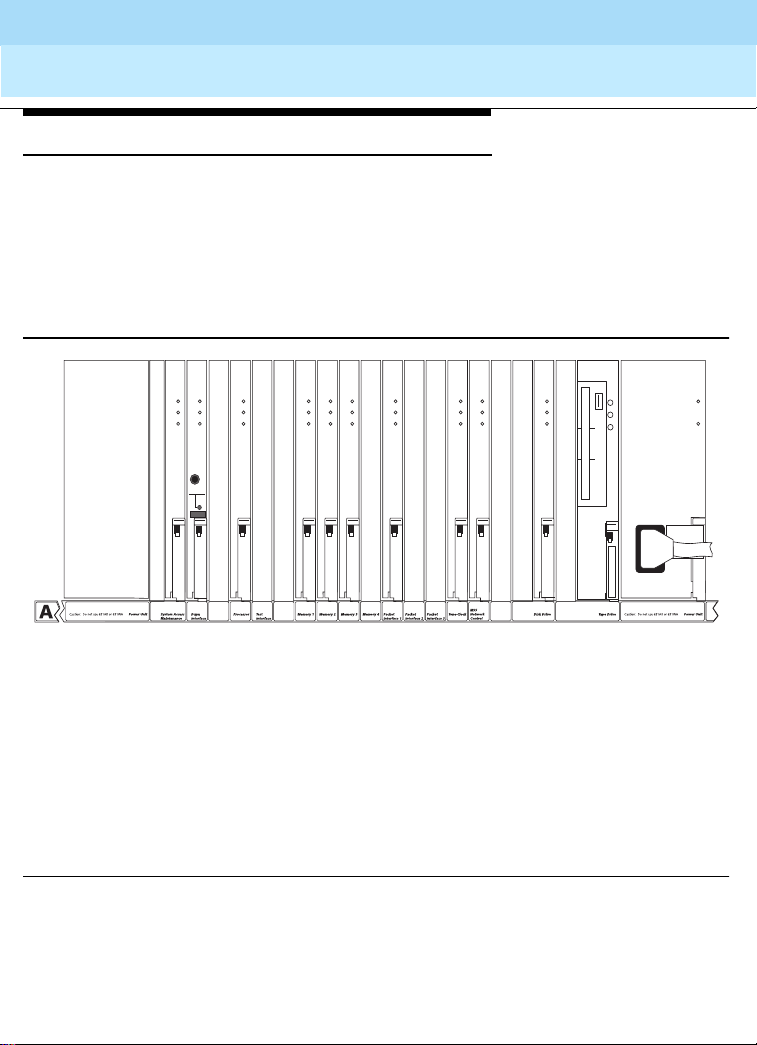
DEFINITY Enterprise Communications Server Release 8.2
System Description
555-233-200
Issue 1
April 2000
Cabinets, Carriers, and Circuit Packs
Carriers in MCCs
J58890AP Processor Carrier (r model)
The Processor Carrier contains only dedicated slots for control circuit packs composing
not
the Switch Processing Element (SPE). It does
Figure 36 for a representative example.
AC or DC power units located at each end of the Processor Carrier supply the power to
the carrier. The Processor Carrier always contains 3 memory circuit packs and 1 packet
interface circuit pack. See Table 16 for the Processor Carrier rear connector descriptions.
contain port circuit pack slots. See
85
Z100A1
blanks
or
OVERRIDE
SPE
AUTO
A
B
631DA1
B
B
l
a
n
k
T
Z
U
N
1
N
1
0
3
6
0
3
4
C
0
8
B
B
l
l
a
a
n
n
k
k
T
T
U
N
3
3
1
B
T
N
N
N
1
1
1
6
6
6
5
5
5
0
0
0
B
B
B
B
B
l
a
n
k
B
l
l
a
a
n
n
k
k
T
N
1
6
5
5
T
U
N
N
7
3
8
3
0
2
or
C
T
N
2
1
8
2
Figure 36. Processor Carrier (r model) (J58890AP) (Front)
631DB1
or
649A
B
l
a
n
k
T
N
1
6
5
7
TN2211 OPTICAL DRIVE
CAUTION: DO
T
N
2
2
1
1
ccdfr8ap LJK 121399

DEFINITY Enterprise Communications Server Release 8.2
System Description
Cabinets, Carriers, and Circuit Packs
555-233-200
April 2000
Carriers in MCCs
Table 16. J58890AP Processor Carrier (r model) Connectors
Connector Function
Clock (stratum-3) Provides an interface to a stratum-3 clock for digital frame timing.
This is not a time-of-day clock
AUX (Auxiliary) Provides an interface for customer alarms, attendant console
power, emergency power-tra nsfer pan els, an d an intern al-mod em
interface for remote maintenance
Terminal, active Connects a management terminal to the system access and
maintenance (SYSAM) circuit pack in the active Processor Carrier
Terminal, standby Used only in Duplicated Processors to connect a management
terminal to the standby processor carrier
P1 Provides position indicator of the carrier and access to alarm and
control circuits
P2 Provides control signals to the carrier
Continued on next page
Issue 1
86

DEFINITY Enterprise Communications Server Release 8.2
System Description
555-233-200
Cabinets, Carriers, and Circuit Packs
Carriers in MCCs
J58890BB Port Carrier
A Port Carrier contains the following circuit packs:
■ Port slot locations 1 to 20 for the port circuit packs. A dedicated slot contains an
optional tone-clock circuit pack used for Port Carriers in the B position of an EPN
cabinet in critica l rel iabili ty s ystem s. Sl ot 2 c ontai ns an opti onal EI o r ATM Interface
circuit pack
■ Power unit service slots in which power unit circuit packs or maintenance circuit
packs can install
■ AC or DC power units located at each end of the carrier
See Figure 37 for a representative example. See Table 19 for the Port Carrier rear
connector descripti on s.
Table 17. J58890BB Port Carrier Connectors
Connector Function
1 to 20 Ports interfacing between circuit pack slots and the cross-connect field or
fiber transceiver
P1 Provides position indicator of the carrier and access to alarm and control
circuits
Issue 1
April 2000
87

DEFINITY Enterprise Communications Server Release 8.2
System Description
555-233-200
Cabinets, Carriers, and Circuit Packs
Carriers in MCCs
Z
1
0
0
A
1
B
L
Z
A
1
N
0
K
or
0
S
C
6
3
1
D
A
1
B
Power Unit
B
L
A
N
K
POWER UNIT
SERVICE
T
T
T
N
N
N
2
5
5
1
7
7
8
0
0
2
B
B
TONE
EXPN
EXPN
CLOCK
INTFC
INTFC
2 3 195 6 7 8 9 10 11 12
13 14
Issue 1
April 2000
88
6
3
1
D
B
1
or
6
4
9
A
15 16 1817 2041
POWER UNIT
Service Service
Port/Service
(BRG)
Port
ccdf0003 RPY081297
Figure 37. J58890BB Port Carrier (Front)

DEFINITY Enterprise Communications Server Release 8.2
System Description
555-233-200
Issue 1
April 2000
Cabinets, Carriers, and Circuit Packs
Carriers in MCCs
J58890AF Expansion Control Carrier
The Expansion Co ntro l C a rrie r c on tain s an EI or A T M Interface circui t p ack in port slots 1
and 2. It is used in a fiber optic cabling path to another cabinet or the CSS in the same
cabinet. These slots may contain optional port circuit packs. See Figure 38 for a
representative example.
The Expansion Control Carrier also contains port slots 3 to 19 and the AC or DC power
units. The maintenance and tone-clock circuit packs are also shown. An optional neon
power unit can be in slots 18 and 19. See Table 18 for the Expan si on Control Carrier rea r
connector descripti on s.
Z
1
0
0
A
1
B
L
Z
A
1
N
0
K
0
or
S
C
6
3
1
D
A
1
A
Power Unit
B
L
A
N
K
MAINTENANCE
T
T
T
T
N
N
N
N
2
5
5
7
1
7
7
7
8
0
TONE-
CLOCK
0
2
B
B
EXPN
INTFC
EXPN
INTFC
3
2
1
13 14
15 16 18174
POWER UNIT
195 6 7 8 9 10 11 12
5
B
6
3
1
D
B
1
or
6
4
9
A
POWER UNIT
89
Service
Port
ccdf0004 RPY081297
Figure 38. Expansion Control Carrier (J58890AF) (Front)
Service
Port/Service
(BRG)

DEFINITY Enterprise Communications Server Release 8.2
System Description
555-233-200
April 2000
Cabinets, Carriers, and Circuit Packs
Carriers in MCCs
Table 18. Expan sion Control Carrier (J58890AF) Connectors
Connector Function
1 and 2 (A1 and A2) Provides a fiber-optic cable interface to an expansion interface
(EI) circuit pack in slot 1
1
or a copper cable interface for a DS1
Converter
1 to 19 (A1 to A19) Provides interfaces between port circuit packs and the
cross-connect field
AUX Provides interfaces for customer alarms, attendant console
power, and emergency power transfer panels
TERMINAL Connects a management terminal to the maintenance circuit
pack in an expansion control carrier
P1 Provides position indicator of the carrier and access to alarm
and control circuits
P2 Connects ringing voltage from the ring generator to the carrier
and produces control signals
Continued on next page
Issue 1
90
1.
In systems using ATM-PNC, the fiber connectors fo r the OC-3/STM-1 interfac es to the
ATM switches are located on the faceplates of the TN2305/TN2306 circuit packs.
 Loading...