

Page 1

DEFINITY
®
Enterprise Communication Server
Release 8. 2
Installation for Adjuncts and Peripherals
555-233-116
Comcode 108596420
Issue 1
April 2000
Page 2

Copyright 2000, Lucent Technologies
All Rights Reserved
Printed in U.S.A.
Notice
Every effort was made to ensu re that th e in for mation in this book was
complete and accu ra te at the time o f printing. However , information is
subject to change.
Your Responsibility for Your System’s Security
Toll fraud is the unauthorized use of you r te lecommunications system
by an unauthorized party, for example, persons other than your com-
pany’s employees, agents, subcontractors, or persons working on your
company’s behalf. Note that there may be a risk of toll fraud associated
with your telecommunications system and, if toll fraud occurs, it can
result in substantial additional charges for your telecommunications
services.
This equipment returns answer-supe rvi sion signals on all DID calls
forwarded back to the public sw i tc he d te le phone network. Permissible
exceptions are:
• A call is unanswered
• A busy tone is received
• A reorder tone is received
Canadian Department of Communications (DOC)
Interference Information
This digital apparatus does no t exceed the Class A limits for radio
noise emissions set out in the radi o int er f erence regulations of the
Canadian Department of Com m unications.
Le Présent Appareil Nom
dépassant les limites applicables aux appareils numériques de la class
A préscrites dans le reglement sur le brouillage radioélectrique édicté
par le ministére des Communications du Canada.
érique n’é
met pas de bruits radioélectriques
You and your system manager are responsible for the security of your
system, such as programming and configur ing your e qui pm ent to prevent unauthorized use. The system manager is also responsibl e for
reading all installation, instruc tion, and system administration doc uments provided with this produc t i n orde r to fully understand the features that can introduce risk of toll fraud and the steps that can be taken
to reduce that risk. Lucent Technologies does not warrant that this
product is immune from or will prevent unauthorized use of common-carr ier telecommunication se r v ices or faciliti es accessed thr o u gh
or connected to it. Lucent Technologies will not be responsible for any
charges that result from such unauthorized use.
Lucent Technologies Fraud In te rven tion
If you suspect that you are being victimized by toll fraud and you need
technical support or assistan ce , c al l Technical Service Cen ter Toll
Fraud Intervention Hotlin e at 1 800 643-2353 or contact your loca l
Lucent repr esentative.
Federal Communications Commission Statement
Part 15: Class A S t atement. This equipment has been tested and
found to comply with the limits for a Class A digital device, pursuant to
Part 15 of the FCC Rules. These limits are designed to provide reasonable protection against harmful interference when the equipment is
operated in a commercial environment. This equipment generates,
uses, and can radiate rad io- fre quency energy and, if not installed and
used in accordance with the instructions, may cause harmful interference to radio communications. Operation of this equipment in a residential area is likely to cause harmful interference, in which case the
user will be required to corre c t th e in te rference at his own expense.
Part 68: Network Registration Number. This equipment is registered
with the FCC in accordan ce with Part 68 of the FCC Rules. I t is identified by FCC registration number AS593M-13283-MF-E.
Trademarks
See About This Document.
Ordering Info rm a tion
Call: Lucent Technologies BCS Publications Center
Voice 1 800 457-1235 International Voice 317 322-6416
Fax 1 800 457-1764 International Fax 317 322-6699
Write: Lucent Technologies BCS Publications Center
2855 N. Franklin Road
Indianapolis, IN 46219
Order: Document No. 555-233-116
Comcode 10859642 0
Issue 1, April 2000
For additional documents, refer to the section in “About This Document” entitled “Related Resources.”
Y ou can be placed on a standing order list for this and other documents
you may need. Standing order will enable you to automatically receive
updated versions of individual documents or doc um en t set s , billed to
account information that you provide. For more information on standing orders, or to be put on a list to receive future issues of this do cument, contact the Lucent Technologies Publications Ce nt er.
European Union Declaration of Conformity
The “CE” mark affixed to the DEFINITY® equip ment described in
this book indicates that the e quipment conforms to the foll owing European Union (EU) Directives:
• Electromagne tic Compatibility (89/336/EEC)
• Low Voltage (73/23/EEC)
• T elecommunicat ions T er m inal Equipment (TTE) i-CTR3 BRI
and i-CTR4 PRI
For more information on standards compliance, contact your local distributor.
Part 68: Answer-Supervision Signaling. Allowin g th is eq ui p men t to
be operated in a manner that does not provide proper answer-supervi sion signaling is in violation of Part 68 Rules. This equipment returns
answer-supervision signals to the public switched network when:
• Answered by the called station
• Answered by the attendant
• Routed to a recorded announcement that can be administered by
the CPE user
Comments
T o co mmen t on this document, return the co mme nt card at the front of
the document.
Acknowledgment
This document was prepared by Product Documentation Development,
Lucent Technologies, Denver, CO.
Page 3

DEFINITY ECS Release 8.2
Installation for Adjuncts and Peripherals
555-233-116
Contents
Contents
Contents iii
About This Book vii
■ Overview vii
■ Conventions Used in This Book xii
■ How to Comment on This Document xiii
■ Resources xiv
■ Antistatic Protection xv
■ Remove/Install Circuit Packs xvi
■ Security xvi
■ Trademarks xvi
■ Standards Compliance xvii
■ LASER Product xviii
Issue 1
April 2000
iii
■ Electromagnetic Compatibility Standards xviii
■ Federal Communications Commission Statement xx
1 909A/B Universal Coupler 1
2 Auxiliary Power Supplies 5
■ Local, auxiliary power supply 5
■ Applications that require auxiliary power 6
■ Sources of auxiliary, local power 7
■ Required Safety Precautions 7
■ 1145B Power Supply 8
■ 1151A and 1151A2 Power Supplies 16
3 Voice and Data Terminals and Extenders 19
■ 2-Wire DCP Endpoint 19
■ DEFINITY DCP Extender, Stand Alone 22
■ DEFINITY DCP Extender, Rack Mount 23
4 Data Modules and Asynchronous Data Units 25
■ Understanding RS-232 communications 25
■ Installation Procedure 27
■ Obtain Required Equipment 27
■ Sett Hardware Options 27
■ Connect Data Modules 32
■ Administer the DEFINITY ECS for Data Modules 73
Page 4

DEFINITY ECS Release 8.2
Installation for Adjuncts and Peripherals
555-233-116
Contents
■ Asynchronous Data Units (ADUs) 75
5 External Modems 77
■ Hardware required when configuring modems 77
■ PARADYNE COMSPHERE 3715 78
■ PARADYNE COMSPHERE 3810 Plus and 3811 Plus 79
■ Setting Up the PARADYNE COMSPHERE 3910 79
■ Setting Up the U.S. Robotics Modem
for DEFINITY 87
■ Administering the DEFINITY for Modems 87
6 Printers 91
■ Configuring the AT&T Model 572 91
■ Connecting the Printer 95
■ Okidata Model OP16N 95
7 DEFINITY LAN Gateway System 99
Issue 1
April 2000
iv
■ Installing DEFINITY LAN Gateway in
a Single-Carrier Cabinet 99
■ Installing DEFINITY LAN Gateway in
a Multicarrier Cabinet 101
■ Connecting the Alarm Origination Cable 103
■ Connecting a PC 104
■ Installing a Printer 110
8 DCS Connections 111
9 DS1/T1 CPE Loopback Jack 113
■ Installing Loopback Jacks 113
■ Administering the Loopback Jack 115
■ Loopback Testing with a Smart Jack 115
■ Loopback Testing Without a Smart Jack 123
10 ISDN Converters and Adapters 129
■ Converters for Single-Carrier Cabinets 129
■ Converters for Multicarrier Cabinets 131
11 Stratum 3 Clock 135
■ Set Clock Options 135
Page 5

DEFINITY ECS Release 8.2
Installation for Adjuncts and Peripherals
555-233-116
Contents
12 Busy Tone Disconnect Equipment for
Non-U.S. Installations 143
13 Call Detail Recording Option Settings 145
■ Connecting CDR Equipment to DEFINITY 145
■ Using a Printer as the CDR Output Device 145
■ Using Other Equipment as the CDR Output Devices 147
■ Sources of Administration Information 147
14 DEFINITY INADS 149
15 Malicious Call Trace 159
16 Loudspeaker Paging, Music-on-Hold,
and External Alerting Equipment 161
■ Loudspeaker Paging 161
■ Music-on-Hold, Dial Dictation, or
Recorded Announcement Access 164
Issue 1
April 2000
v
■ External Ringing 166
■ Queue Warning Indicator 166
17 Paging and Announcement Equipment 167
■ PagePac Plus Paging System 167
■ ESPA Radio Paging 170
18 Multimedia Communications
Products: MMCX, MMCH, ESM 173
■ MASI for MMCX 173
■ Wideband Endpoints 175
■ Multimedia Call Handling (MMCH) 178
19 Property Management System 191
■ Connecting the Property Management System 191
■ Connecting a Terminal and/or Journal Printer 192
A Connector and Cable Pinout Charts 195
IN Index 205
Page 6

DEFINITY ECS Release 8.2
Installation for Adjuncts and Peripherals
Contents
555-233-116
April 2000
vi
Issue 1
Page 7

DEFINITY ECS Release 8.2
Installation for Adjuncts and Peripherals
Overview
About This Book
This book provides procedures for installing equipment and software peripheral
to the DEFINITY ECS and DEFINITY ONE, hereafter referred to as DEFINITY . Not
all adjuncts and peripherals are addressed in this book. For those, we are
supplying other resources for the information.
555-233-116
Issue 1
April 2000
vii
The information in this book is intended for use by
Overview
DEFINITY ECS and DEFINITY One can work with a wide range of external
equipment, applications, and peripherals. Adjuncts are Lucent software products
that work with the various DEFINITY switches. Peripherals are Lucent equipment
that connect directly or remotely to DEFINITY switches. Be aware that some
equipment and software work only with certain DEFINITY releases, as noted in
the following table.
■ Lucent and channel partner trained field installation and maintenance
personnel
■ Technical Services Center (TSC) and Global Service Organization (GSO)
personnel
■ InterNetwork Systems (INS) engineers and technicians
■ Sales and Design Support Center (SDSC) personnel
■ Data Services Support Center (DSSC)
■ Sales assoc ia tes
■ Lucent c ha nnel partners
Page 8

DEFINITY ECS Release 8.2
Installation for Adjuncts and Peripherals
Overview
555-233-116
Table 1 provides a list of current adjuncts and which platforms support them.
Table 2 provides a list of current adjuncts and peripherals and where installation
information exists
Table 1. DEFINITY adjunct minimum vintages for Release 8
Issue 1
April 2000
viii
csi
Adjunct
AUDIX (R1V8.2 w/ Y2K
Update)
AUDIX (Voice Power
2.1.1)
BCMS View (R1, R2) Compatible Not
Call Management S ystem
(CMS)
CallVisor ASAI LAN
Gateway (over BRI)
CallVisor ASAI LAN
Gateway (PC)
Centralized Attendant
Service (CAS—NT)
Centralized Attendant
Service (CAS—Terminal)
Call Detail Recording Unit
(CDRU-S, -SE)
R6.1 - R8
Not comp atible Not comp atible Compatible Compatible
Compatible Compatible Compatible
Compatib le Yes if TCP/IP,
Compatible Compatible Compatible Compatible
R6.3.2 and
later
R1.0 Any version
R2.08 Not
R1.0 R1.0 R1.0 R1.0
DEF. ONE
R1
Compatible
else no.
Supported V4 and later R5 and later
that can
transfer the
CDR file from
DEF ONE.
Compatible
si
V4, R6.2 - R8
V4 and later
V4 an d later R5 and later
Compatible Compatible
R1.0 R1.0
R2.08 R2.08
r
R5 - R8
Compatible
R5 and later
CentreVu Agent R6.1 and later Supported for
CMS that is
TCP/IP
capable.
CentreVu Explorer R7 and later Supported for
CMS R3V6 that
is TCP/IP
capable.
CentreVu Supervisor (V5
B107 and later)
R7 and later Supported for
CMS R3V6 that
is TCP/IP
capable.
R6.1 and later R6.1 and later
R5.1 and later R5.1 and later
R5.1 and later R5.1 and later
Continued on next page
Page 9

DEFINITY ECS Release 8.2
Installation for Adjuncts and Peripherals
Overview
555-233-116
Table 1. DEFINITY adjunct minimum vintages for Release 8
Issue 1
April 2000
ix
csi
Adjunct
Conversant R6.3.2 and
DEFINITY Proxy Agent R6.1 and later Not Supported V4 and later R5 and later
DEFINITY Wireless
Personal Comm Mgr.
(R1.2)
Hacker Tracker Module of
CAS for Windows (2.0
and later)
Internet Call Center R6.3 and later Supported R6.3 and later R6.3 and later
Internet Telephony
Gateway (R1.2, R2.0)
Intuity AUDIX Not
Intuity CAS R1.2 Not Supported R1.2 R1. 2
Intuity Interchange Supported Supported Supported Supported
R6.1 - R8
later; some
vintages,
connectivity
only
Compatible Supported R6.2 and later R6.2 and later
R2.2B
(Supported via
CAS)
R6.3 and later Supported R6.3 and later R6.3 and later
Compatible
DEF. ONE
R1
Supported;
some vintages,
conne ctiv i ty
only
Supported via
CAS
Not Suppo rted Compatible Compati ble
si
V4, R6.2 - R8
V3.0 .1: som e
vintages,
connectivity
only
R2.2B
(S upported via
CAS)
r
R5 - R8
V3.0.1; some
vintages,
connectivity
only
R2.2B
(Su pport ed via
CAS)
Message Manager (4.3 &
later)
Multipoint Control Unit
(MCU)/CRS
OneMeeting / DEFINITY
Anywhere
PassageWay Direct
Connect for DEFINITY
Pollable Storage Unit
(PSU)
Supported Supported Supported Supported
R1.0 R1.0 R1.0 R1.0
R6.3csi and
later
Supported Supported Supported Supported
R1.1 Not Supported R1.1 R1.1
Supported V4 in office
only, R6.3 and
later w/MAPD
for remote
R6.3 and later
w/MAPD for
remote
Continued on next page
Page 10

DEFINITY ECS Release 8.2
Installation for Adjuncts and Peripherals
Overview
555-233-116
Table 1. DEFINITY adjunct minimum vintages for Release 8
Issue 1
April 2000
x
Adjunct
Remote Port Security
Device Key/Lock (4.0 and
later)
Tele communications
Management System
(TMS)
Terranova ECS Statio n
Administration (R6.0)
csi
R6.1 - R8
Compatible Compatible Co mpatible Compatible
R1.1 Not Supported R1.1 R1.1
Compatible Supported.
DEF. ONE
R1
TCP/IP only
si
V4, R6.2 - R8
V4 an d later R5 and later
r
R5 - R8
Continued on next page
Table 2. DEFINITY adjuncts and peripheral resource list
Adjunct/Peripheral Resource
909A/B Universal Coupler DEFINITY ECS Release 8 Adjuncts and Peripherals, Chapter 1
AUDIX AUDIX Installation
AUDIX Voice Power R2.1.1 Installation and Maintenanc e Guide
http://pubcat.lucent.com/iw/owa/pcat.prod_result
Auxiliary Power Supplies DEFINITY ECS Release 8 Adjuncts and Peripherals, Chapter 2
Basic Call Management
System (BCMS) View
Busy Tone Disconnect
Equipment for Non-U.S.
Installations
Call Detail Recording (CDR)
Option Settings
CallVisor ASAI LAN Gateway DEFINITY ECS CallVisor ASAI DEFINITY LAN Gateway over
CentreVu Agent CentreVu® Agent Installation and Administration
CentreVu Call Management
System (CMS)
CentreVu Explorer CentreVu® Explorer V1.2 User Guide
CentreVu Supervisor CentreVu
Conversant INTUITY CONVERSANT System Customer Assist Technical
Basic Call Management System (BCMS) Operations
DEFINITY ECS Release 8 Adjuncts and Peripherals,
DEFINITY ECS Release 8 Adjuncts and Peripherals, Ch apte r 13
MAPD Installation, Administration, and Maintenance
CentreVu
Setup
Operations
®
Call Management System Software Installation and
®
Supervisor Version 8—Installation and Getting Started
Chapter 12
Continued on next page
Page 11

DEFINITY ECS Release 8.2
Installation for Adjuncts and Peripherals
Overview
555-233-116
April 2000
Table 2. DEFINITY adjuncts and peripheral resource list — Continued
Adjunct/Peripheral Resource
Data Modules and ADUs DEFINITY ECS Release 8 Adjuncts and Peripherals, Ch apter 4
DCS Connections DEFINITY ECS Release 8 Adjuncts and Peripherals, Chapter 8
DEFINITY INADS DEFINITY ECS Release 8 Adjuncts and Peripherals, Chapter 14
DEFINITY LAN Gateway
System
DEFINITY ECS Release 8 Adjuncts and Peripherals, Ch apte r 7
Issue 1
xi
DEFINITY Wireless Personal
Comm Mgr.
DS1/T1 CPE Loopba ck Jack DEFINITY ECS Release 8 Ad juncts and Peripherals,
Expan sion Services Module
(ESM)
External Alerting Equipment DEFINITY ECS Release 8 Adjuncts and Peripherals, Chapter 16
Internet Call Center CentreVu Internet Solutions R3 Documentation CD-ROM
Internet Telephony Gateway Internet Telephony Server-Enterprise Hardware Installation Quick
Intuity AUDIX Internet Messaging for the Intuity AUDIX Multimedia Messaging
Intuity Interchange INTUITY Interchange Release 5.2 Sy stem Supporting
ISDN Converters and
Adapters
Loudsp eaker Paging DEFI NITY ECS Release 8 Adjuncts and Peripherals, Ch apte r 17
Malicious Call Trace DEFINITY ECS Release 8 Adjuncts and Peripherals, Chapter 15
Modems, external DEFINITY ECS Release 8 Adjuncts and Peripherals, Ch apte r 5
Multimedia Call
ExchangeMMCX
DEFINITY ECS Interface for the DEFINITY Wireless Business
System Guide
Chapter 9
DEFINITY ECS Release 8 Adjuncts and Peripherals, Ch apte r 18
Internet Call Center Solution Guide, R3
Reference
System, Release 1.1 Installation
Documentation
DEFINITY ECS Release 8 Adjuncts and Peripherals, Ch apte r 10
DEFINITY ECS Release 8 Adjuncts and Peripherals, Ch apte r 18
Multimedia Call Handling
(MMCH)
Multipoint Control Unit
(MCU)/CRS
Music on Hold DEFINITY ECS Release 8 Adjuncts and Peripherals, Chapter 16
Paging and Announcement
Equipment
Pollable Storage Unit (PSU) Pollable Storage Unit Installation
Printers DEFINITY ECS Release 8 Adjuncts and Peripheral s, Chapter 6
DEFINITY ECS Release 8 Adjuncts and Peripherals, Ch apte r 18
MultiPoint Conferencing Unit Release 5.0 Installation and Test
DEFINITY ECS Release 8 Adjuncts and Peripherals, Ch apte r 17
Continued on next page
Page 12

DEFINITY ECS Release 8.2
Installation for Adjuncts and Peripherals
Conventions Used in This Book
555-233-116
April 2000
Table 2. DEFINITY adjuncts and peripheral resource list — Continued
Adjunct/Peripheral Resource
Property Management System DEFINITY ECS Release 8 Adjuncts and Peripherals, Chapter 19
Stratum 3 Clock DEFINITY ECS Release 8 Adjuncts and Peripherals, Ch apte r 11
Voice and Data Terminals DEFINITY ECS Release 8 Adjuncts and Peripherals, Chapter 3
Continued on next page
Conventions Used in This Book
Typographic
■ Information you type at the access terminal is shown in the following
typeface:
list system-parameters maintenance
.
Issue 1
xii
■ Variables are shown in the following typeface:
■ Field names and information displayed on the access terminal screen is
shown in the following typeface:
■ Keyboard keys are shown in the following typeface: Enter.
Systems and circuit packs
■ The word “system” is a general term encompassing Release 8 and
includes references to the DEFINITY Enterprise Communications Server
models: Release 8r, Release 8si, Release 8csi, and Release 8c.
■ DEFINITY Enterprise Communications Server is abbreviated as DEFINITY
ECS.
■ Circuit pack codes (for example, TN780 or TN2182B) are shown with the
minimum acceptable alphabetic suffix (like the “B” in the code TN2182B).
Generally, an alphabetic suffix higher than that shown is also acceptable.
However, not every vintage of either the minimum suffix or a higher suffix
code is necessarily acceptable.
■ The term “ASAI” is synonymous with the newer CallVisor ASAI.
login
number
.
.
Page 13

DEFINITY ECS Release 8.2
Installation for Adjuncts and Peripherals
How to Comment on This Document
Admonishments
Admonishments in this book have the following meanings:
!
CAUTION:
This sign is used to indicate possible harm to software, possible loss
of data, or possible service interruptions.
!
WARNING:
This sign is used where there is possible harm to hardware or
equipment.
!
DANGER:
This sign is used to indicate possible harm or injury to people.
Physical dimensions
555-233-116
Issue 1
April 2000
xiii
■ All physical dimensions in this book are in English units (feet [ft]) followed
by metric (centimeter [cm]) in parenthesis.
■ Wire gauge measurements are in AWG followed by the diameter in
millimeters in parenthesis
How to Comment on This Document
Lucent Technologies welcomes your feedback. Your comments are of great value
and help improve our documentation.
■ Please fill out the reader comment card at the front of this manual and
return it.
■ If the reader comment card is missing, FAX your comments to
1-303-538-1741 or to your Lucent Technologies representative, and
mention this document’s name and number, DEFINITY Enterprise
Communication Server Release 8 ATM Installation, Upgrade, and
Administration, 555-233-124, Issue 1.
■ Email your comments to
document@drmail.lucent.com
Page 14

DEFINITY ECS Release 8.2
Installation for Adjuncts and Peripherals
Resources
Resources
Related Books
The following books are useful for system-related information:
■ DEF INITY Enterprise Communications Server Release 8 Administration for
Network Connectivity
■ DEFINITY Enterprise Communications Server Release 8 System
Description
■ DEFINITY Enterprise Communications Server Release 8 Maintenance for
R8r
■ DEFINITY Enterprise Communications Server Release 8 Maintenance for
R8si
■ DEFINITY Enterprise Communications Server Release 8 Maintenance for
R8csi
555-233-116
Issue 1
April 2000
xiv
■ AT&T Network and Data Connectivity Reference
■ DEFINITY Enterprise Communications Server Release 8 Installation and
Test for Multicarrier Cabinets
■ DEFINITY Enterprise Communications Server Release 8 Installation and
Test for Single-Carrier Cabinets
■ DEFINITY Enterprise Communications Server Release 8 Installation,
Upgrades, and Additions for Compact Modular Cabinets
■ DEFINITY Enterprise Communications Server Release 8 Administrator’s
Guide
■ DEFINITY Enterprise Communications Server Release 8 Upgrades and
Additions for R8si
■ DEFINITY Enterprise Communications Server Release 8 Upgrades and
Additions for R8r
How to Order Books
In addition to this book, other description, installation and test, maintenance, and
administration books are available. A complete list of DEFINITY books can be
found in the Business Communications System Publications Catalog.
This book and any other DEFINITY books can be ordered directly from the
Luc ent Technologies Busines s Comm uni cations System Publications Fulfillment
Center at 1-317-322-6791 or toll free at 1-800-457-1235.
Page 15

DEFINITY ECS Release 8.2
Installation for Adjuncts and Peripherals
Antistatic Protection
555-233-116
Where To Call for Technical Support
Use the telephone numbers in Tab l e 1 for the region in which the system is being
installed.
Table 1. Technical support contact numbers
Issue 1
April 2000
xv
Tel ep h o n e N um b e r
DEFINITY Helpline (feature administration and system
applications)
Luc ent Tec hnologies Toll Fraud Intervention 1-800-643-2353
Lucent Technologies National Customer Care Center (ATM
customers)
Lucent Technologies Corporate Security 1-800-822-9009
Streamlined Implementation (for missing equipment) 1-800-772-5409
USA/Canada Technical Service Center (ATM technicians) 1-800-248-1234
NetCare® Professional Services (NPS) 1-800-237-0016
International Technical Assistance (ITAC) 1-303-804-3777
Luc ent Tec hnol ogies Centers of Exce lle nce
Asia/Pacific Regional Support Center 65-872-8686
Western Europe/Middle East/South Africa 44-1252-77-4800
Central/Eastern Europe 361-345-4334
Central/Latin America Caribbean 1-303-804-3778
Australia 61-2-9352-9090
North America (INADS Database Administratio n) 1-800-248-1111
1-800-225-7585
1-800-242-2121
Antistatic Protection
!
WARNING:
To minimize electrostatic discharge (ESD), always wear an authorized wrist
ground strap when handling circuit packs or any components of a
DEFINITY System. Connect the strap to an approved ground such as an
unpainted metal surface on the DEFINITY ECS switch.
Page 16

DEFINITY ECS Release 8.2
Installation for Adjuncts and Peripherals
Remove/Install Circuit Packs
Remove/Install Circuit Packs
!
CAUTION:
The control circuit packs with white labels cannot be removed or installed
when the power is on. The port circuit packs with gray labels (older version
circuit packs had purple labels) can be removed or installed when the
power is on.
Security
To ensure the greatest security possible, Lucent Technologies offers services that
can reduce toll fraud liabilities. Contact your Lucent Technologies representative
for more security information.
Login security is an attribute of the DEFINITY ECS software. Advise customers
that their existing passwords expire 24 hours after the upgrade. Also explain that
the new passwords must conform to strict requirements.
555-233-116
Issue 1
April 2000
xvi
System administrators must keep network addresses confidential. A PPN or any
endpoint masquerading as a PPN on the ATM network can seize that EPN and
control it if that EPN is not already connected to its proper PPN.
Trademarks
This document contains references to the following Lucent Technologies
trad em arke d prod ucts:
■ ACCUNET
■ AUDIX
■ Callmaster
■ CallVisor
■ CentreVu
■ CONVERSANT
■ DEFINITY
■ DEFINITY ONE
■ FORUM
■ Intuity
■ Intuity Lodging
■ MEGACOM
■ MULTIQUEST
■ OneVision
®
®
®
®
™
®
®
™
™
™
™
®
®
™
Page 17

DEFINITY ECS Release 8.2
Installation for Adjuncts and Peripherals
Standards Compliance
555-233-116
Issue 1
April 2000
xvii
■ Quorum
■ SYSTIMAX
■ TRANSTALK
■ VOICE POWER
™
®
™
®
The following products are trademarked by their corresponding vendor:
■ 3Comm
®
, U.S . Robotics®, and Sportster® are registered trademarks of the
3Comm Corporation
■ Audichron
■ LINX
■ Windows95/98/NT is a trademark of Microsoft Corporation
■ Music Mate
■ PagePac
®
is a registered trademark of Audichron Company
™
is a trademark of Illinois Tool Works, Inc.
®
is a registered trademark of Harris Corporation
®
is a registered trademark of Harris Corporation, Dracon
Division
■ Paradyne
™
and COMSPHERE™are trademarks of the Paradyne
Corporation
■ Shockwatch
■ Styrofoam
■ Tiltwatch
■ Zone Mate
®
is a registered trademark of Media Recovery, Incorporated
®
is a registered trademark of Styrofoam Corporation
®
is a registered trademark of Media Recovery, Incorporated
®
is a registered trademark of Harris Corporation
Standards Compliance
The equipment in this document complies with the following standards (as
applicable):
■ ITU-T (Formerly CCITT)
■ ECMA
■ ETSI
■ IPNS
■ DPNSS
■ National ISDN-1
■ National ISDN-2
■ ISO-9000
■ ANSI
■ FCC Part 15 and Part 68
■ EN55022
Page 18

DEFINITY ECS Release 8.2
Installation for Adjuncts and Peripherals
LASER Product
■ EN50081
■ EN50082
■ UNI 3.1
■ CISPR22
■ Australia AS3548 (AS/NZ3548)
■ Australia AS3260
■ IEC 825
■ IEC 950
■ UL1459
■ UL 1950
■ CSA C222 Number 225
■ TS001
■ ILMI 3.1
555-233-116
Issue 1
April 2000
xviii
LASER Product
The DE FINITY ECS switch may contain a Class 1 LASE R device (IEC 825 1993) if
single-mode fiber optic cable is connected to a remote expansion port network
(EPN). The laser device operates within the following parameters:
Power output Wavelength Mode field diameter
-5 dBm 1310 nm 8.8 mm
!
DANGER:
Use of controls or adjustments or performance of procedures other than
those specified herein may result in hazardous radiation exposure.
Contact your Lucent Technologies representative for more information.
Electromagnetic Compatibility Standards
This product complies with and conforms to the following EMC standards (as
applicable):
■ Limits and Methods of Measurements of Radio Interference
Characteristics of Information Technology Equipment, EN55022
(CISPR22), 1993
■ EN50082-1, European Generic Immunity Standard
Page 19

DEFINITY ECS Release 8.2
Installation for Adjuncts and Peripherals
Electromagnetic Compatibility Standards
■ FCC Part 15
■ Australia AS3548
NOTE:
The DEFINITY system conforms to Class A (industrial) equipment. Voice
terminals meet Class B requirements.
■ Electrostatic Discharge (ESD) IEC 1000-4-2
■ Radiated radio frequency field IEC 1000-4-3
■ Electrical Fast Transient IEC 1000-4-4
■ Lightning effects IEC 1000-4-5
■ Conducted radio frequency IEC 1000-4-6
■ Mains frequency magnetic field IEC 1000-4-8
■ Low frequency mains disturbance IEC 1000-4-11
European Union Standards
555-233-116
Issue 1
April 2000
xix
Lucent Technologies Business Communications Systems declares that the
DEFINITY equipment specified in this document bearing the “CE” mark conforms
to the European Union Electromagnetic Compatibility Directives.
The “CE” (Conformité Europeénne) mark indicates conformance to the European
Union Electromagnetic Compatibility Directive (89/336/EEC) Low Voltage
Directive (73/23/EEC) and Telecommunication Terminal Equipment (TTE)
Directive (91/263/EEC) and with i-CTR3 Basic Rate Interface (BRI) and i-CTR4
Primary Rate Interface (PRI) as applicable.
The “CE” mark is applied to the following products:
■ Global AC-powered Multicarrier Cabinet (MCC) with 25-Hz and 50-Hz ring
generator
■ DC-powered Multicarrier Cabinet (MCC) with 25-Hz ring generator
■ AC-powered Enhanced Single-Carrier Cabinet (ESCC) with 25-Hz ring
generator
■ AC-powered Compact Single-Carrier Cabinet (CSCC) with 25-Hz ring
generator
■ AC-powered Compact Modular Cabinet (CMC) with 25-Hz and 50-Hz ring
generator (for France)
■ Enhanced DC Power System
Page 20

DEFINITY ECS Release 8.2
Installation for Adjuncts and Peripherals
Federal Communications Commission Statement
555-233-116
Federal Communications Commission
Statement
Part 68: Statement
Part 68: Answer-Supervision S ignaling. Allowing this equipment to be operated in
a manner that does not provide proper answer-supervision signaling is in
violation of Part 68 rules. This equipment returns answer-supervision signals to
the public switched network when:
■ Answered by the called station
■ Answered by the attendant
■ Routed to a recorded announcement that can be administered by the CPE
user
This equipment returns answer-supervision signals on all domestic DID calls
forwarded back to the public switched telephone network. Permissible
exceptions are:
Issue 1
April 2000
xx
■ A call is unanswered
■ A busy tone is received
■ A reorder tone is received
Lucent Technologies attests that this registered equipment is capable of
providing users access to interstate providers of operator services through the
use of access codes. Modification of this equipment by call aggregators to block
access dialing codes is a violation of the Telephone Operator Consumers Act of
1990.
This equipment complies with Part 68 of the FCC Rules. On the rear of this
equipment is a label that contains, among other information, the FCC registration
number and ringer equivalence number (REN) for this equipment. If requested,
this information must be provided to the telephone company.
The REN is used to determine the quantity of devices which may be connected
to the telephone line. Excessive RE Ns on the telephone line may result in devices
not ringing in response to an incoming call. In most, but not all areas, the sum of
RENs should not exceed 5.0. To be certain of the number of devices that may be
connected to a line, as determined by the total RENs, contact the local telephone
company.
NOTE:
REN is not required for some types of analog or digital facilities.
Page 21

DEFINITY ECS Release 8.2
Installation for Adjuncts and Peripherals
Federal Communications Commission Statement
555-233-116
Means of connection
Connection of this equipment to the telephone network is shown in the following
table.
Issue 1
April 2000
xxi
Manufacturer’s
Port Identifier FIC Code
SOC/REN/
A.S. Code Network Jacks
Off/On Premises Station OL13C 9.0F RJ2GX,
RJ21X, RJ11C
DID trunk 02RV2-T 0.0B RJ2GX, RJ21X
CO trunk 02GS2 0.3A RJ21X
CO trunk 02LS2 3.0A RJ21X
Tie trunk TL31M 9.0F RJ2GX
1.544 digital Interface 04DU9-B,C 6.0F RJ48C, RJ48M
1.544 digital Interface 04DU9-BN,KN 6.0F RJ48C, RJ48M
2.048 digital Interface 04DU9-BN,KN 6.0F RJ48C, RJ48M
120A2 channel service unit 04DU9-DN 6.0F RJ48C
If the terminal equipment (DEFINITY
®
System) causes harm to the telephone
network, the telephone company will notify you in advance that temporary
discontinuance of service may be required. But if advance notice is not practical,
the telephone company will notify the customer as soon as possible. Also, you
will be advised of your right to file a complaint with the FCC if you believe it is
necessary.
The telephone company may make changes in its facilities, equipment,
operations or procedures that could affect the operation of the equipment. If this
happens, the telephone company will provide advance notice in order for you to
make necessary modifications to maintain uninterrupted service.
If trouble is experienced with this equipment, for repair or warranty information,
please contact the Technical Service Center at 1-800-242-2121. If the equipment
is causing harm to the telephone network, the telephone company may request
that you disconnect the equipment until the problem is resolved.
It is recommended that Lucent Technologies-certified technicians perform the
repairs.
The equipment cannot be used on public coin phone service provided by the
telephone company. Connection to party line service is subject to state tariffs.
Contact the state public utility commission, public service commission or
corporation commission for information.
This equipment, if it uses a telephone receiver, is hearing-aid compatible.
Page 22

DEFINITY ECS Release 8.2
Installation for Adjuncts and Peripherals
Federal Communications Commission Statement
555-233-116
Issue 1
April 2000
xxii
Page 23

DEFINITY ECS Release 8.2
Installation for Adjuncts and Peripherals
909A/B Universal Coupler
1
909A/B Universal Coupler
The 909A/B Universal Coupler is used with paging and music-on-hold equipment
that is not approved for use with the public network.
555-233-116
Issue 1
April 2000
1
1
NOTE:
If the music source is registered by the FCC (in the USA) or an equivalent
body, the 909A/B is not required.
Figure 1
switch setting information, refer to 909A/909B Universal Coupler Installation
Instructions.
shows a typical 909A/B universal coupler. For additional installation and
Page 24

DEFINITY ECS Release 8.2
Installation for Adjuncts and Peripherals
909A/B Universal Coupler
1
555-233-116
Issue 1
April 2000
2
909_brkt KLC 042296
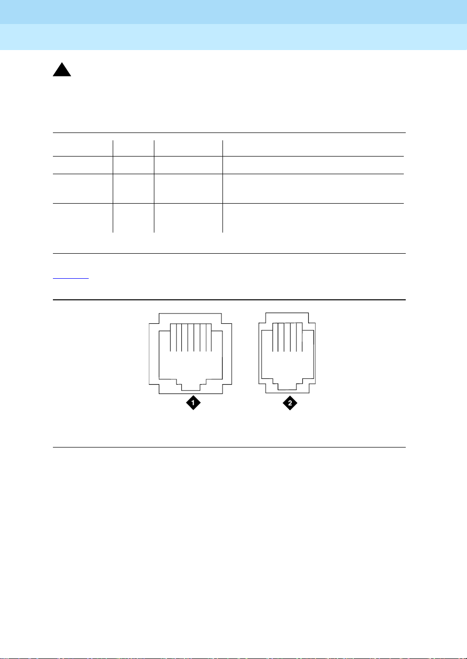
1. 909A/B universal coupler
2. J1 8-Pin modular jack
4. J3 7-Pin modular jack
5. DIP switch location
3. J2 8-Pin modular jack
Figure 1. Typical 909A/B Universal Coupler
The 909A is the DC version of the coupler, and cabinet power supplies -48 VDC
power. The 909B is the AC-powered version and power is supplied from a
separate power supply (such as the KS-22911L2).
The DIP switches on the unit set:
■
Protection/Paging selection
— For AUX trunk paging and malicious call
trace, set to C2. Set the switch to C1 for all other applications.
■
Output attenuation (-9 or -15 dBm)
— Setting depends on output level of
music source.
■
Output impedance (8 ohms, 1.5 kΩ, and 50 kΩ)
—This switch only
requires setting if the Protection/Paging switch is set to C2 and the coupler
is supplying background music to a customer-supplied paging amplifier.
The pinouts for J1, J2, and J3 are provided in Ta b le 1
Tab l e 3
. Refer to these tables when connecting music or paging equipment.
, Table 2, and
Page 25

DEFINITY ECS Release 8.2
Installation for Adjuncts and Peripherals
909A/B Universal Coupler
1
555-233-116
Table 1. J1 Pin Assignments (System Connections)
Pin Color Designation Description
Issue 1
April 2000
3
1 White-Orange
—
Not Used
2 Orange PG2/BZ2 Seizure control lead, connected to -48 VDC from
the system or from the 909A/B when the
protection paging switch is set to C2, or to -48
VDC on the 909A/B when protection/paging
switch is set to C1
3 White-Green PG1/BZ1 Seizure control lead, connected to SZ lead from
the AUX trunk when the protection/paging switch
is set to C2, or to -48 VDC on the 909A/B when the
protection/paging switch is set to C1
4 Blue R Ring lead
5 White-Blue T Tip lead
7 Green BSY2/BY2 Busy/busy-out lead, connected to S1 lead from
the AUX trunk
7 White-Brown BSY1/BY1 Busy/busy-out lead, connected to S lead from the
AUX trunk
8Brown
—
Not Used
Table 2. J2 Pin Assignments (Accessory Connections)
Pin Color Designation Description
1 White-Orange CMS1/M1 Customer-supplied music source
2 Orange CMS2/M2 Customer-supplied music source
3 White-Green COS1 Remote busy-out control contact closure from
music source
4 Blue CR Customer ring lead
5 White-Blue CT Customer tip lead
7 Green COS2 Remote busy-out control contact closure from
music source
7 White-Brown CBS1/C1 Seizure indication provided to music source
8 Brown CBS2/C2 Seizure indication provided to music source
Page 26
DEFINITY ECS Release 8.2
Installation for Adjuncts and Peripherals
909A/B Universal Coupler
1
!
CAUTION:
Damage to the 909A/B may occur if the cable is plugged into J3
cross-connects are completed.
Table 3. J3 Pin Assignments (Power Connections)
Pin Color Designation Description
1, 3, 4, & 7 — — Not used
2 Black GRD -48 RE T or ground lead from system or
5 Yellow -48 VDC -48 VDC from system or from negative
Figure 2 shows the physical locations of the pins for J1, J2, and J3.
555-233-116
April 2000
before
from positive lead of power supply
lead of power supply
Issue 1
4
all
18
mod_jack RBP 041796
2
5
1. J1 and J2 8-Pin modular jacks 2. J3 7-Pin modular jack
Figure 2. Typical Modular Jack Pinout
Page 27

DEFINITY ECS Release 8.2
Installation for Adjuncts and Peripherals
Auxiliary Power Supplies
2
Auxiliary Power Supplies
Nonessential features of the attendant console, such as the optional 27B1
selector console, and DCP terminals derive their power from an auxiliary power
source. One console can connect to R8csi, and 3 consoles can connect to each
cabinet stack or R8r. Each cabinet can derive auxiliary power from the system
and through the auxiliary cable located in the trunk/auxiliary field. Auxiliary power
for a primary attendant console should be provided through this cable so the
console remains fully operational during short power outages.
555-233-116
Issue 1
April 2000
5Local, auxiliary power supply
2
Local, auxiliary power supply
Consoles can use either local or phantom power, depending on the distance
between the console and the DEFINITY ECS cabinet. Over short distances,
phantom power is attractive, because no additional hardware is necessary—
power is supplied via the telephone circuit itself. For longer distances, you need
a local power supply. Ta b le 4
console.
shows cabling distances for the 302C1 attendant
Page 28

DEFINITY ECS Release 8.2
Installation for Adjuncts and Peripherals
Auxiliary Power Supplies
2
Table 4. 302C1 Attendant Console Cabling Distances
555-233-116
Issue 1
April 2000
6Applications that re quire auxiliary power
24 AWG Wire
(0.27 mm
feet meters feet meters
With selector console:
Phantom-powered 800 244 500 152
Locally powered 5000 1524 3400 1037
Without selector console:
Phantom powered 1400 42 7 900 274
Locally powered 5000 1524 3400 1037
Applications that require auxiliary power
Auxiliary power (local or bulk) is always required for the following:
■
Any 8520 terminal
■
Attendant console 302C1
■
PassageWay adapter interface
2
27 AWG Wire
)
(0.14 mm2)
■
Any 7500-series terminal whether in passive bus, or point to point (one per
BRI port)
■
Any 7500- or 8500-series terminal with an asynchronous data module
■
Any 8510 terminal in passive bus or with an asynchronous data module
(unless the 8510 will not be used to support data or video)
■
Any 7400-series terminal with XM24 expansion module
■
Any 7400-series terminal with adjuncts 7407, 7434 or 7444
■
Any 8400-series terminal with adjuncts 8411 or 8434
The 1145B power supply is required for all installations outside the United States.
Page 29

DEFINITY ECS Release 8.2
Installation for Adjuncts and Peripherals
Auxiliary Power Supplies
2
555-233-116
Sources of auxiliary, local power
An attendant console can derive auxiliary power from:
■
A bulk power supply, such as the 1145B
A console’s maximum distance from its 1145B auxiliary power source is
800 ft (244 m) for a 302A1 or 350 ft (107 m) for a 301B1 and 302C1.
■
1151A1 or 1151A2 power supply
Required Safety Precautions
!
DANGER:
When operating power-supply equipment, you must follow basic safety precautions to
reduce the risk of fire, electric shock and personal injury. Read and understand all
instructions. Follow all warnings and instructions marked on the products. Follow all
the instal lation instructions when mounting the product.
Issue 1
April 2000
7Sources of auxiliary, local power
!
DANGER:
Never use a power unit with a power source other than that specified on the product
labels.
Do not try to plug the 3-wire grounding plug into a nongrounding power outlet. This
plug only fits into a grounding power outlet. This is a safety feature. If you are unable to
insert the plug into the outlet, have an electrician replace the outlet. Do not defeat the
safety purpose of the grounding plug.
Do not attach the power supply cord to building surfaces.
Do not overload power outlets.
Do not use this product near water. Do not let anything spill on or into the unit. Clean
only with a dry rag.
Never push objects through openings in the case.
Do not try to disassemble the unit. Return it for repair. Opening or removing covers
may expose you to dangerous voltages. Incorrect reassembly may cause electric
shock when the products are subsequently used.
Power down the unit and refer servicing immediately if the unit is exposed to water or
other liquids, if the unit is dropped or damaged, or if the unit fails to operate normally.
Page 30

DEFINITY ECS Release 8.2
Installation for Adjuncts and Peripherals
Auxiliary Power Supplies
2
!
DANGER:
Never let the operating temperature of the unit exceed the recommended maximum.
Do not block or cover the ventilation openings in the case.
Do not let anything rest on the unit.
!
DANGER:
Do not attempt to recharge batteries. The power unit recharges the batteries itself.
Any other recharging method may cause leaks of corrosive electrolyte or explosion.
Discard discharged batteries as soon as possible. Discharged batteries are more
likely to leak.
Do not store batteries in high temperature areas. Batteries stored in a cold
environment should be protected from condensation during storage and warming.
Batteries should be stabilized at room temperature prior to use after cold storage. Do
not install batteries if the manufacturing date on the label indicates that the batteries
are more than 6 months old.
555-233-116
Issue 1
April 2000
81145B Power Supply
1145B Power Supply
The 1145B power supply powers ISDN/DCP, terminal equipment, adjuncts, and
other customer-supplied external equipment. It supplies -48V, 200 W total and
supports 32 outputs. You can install one ISDN terminal or DCP adjunct per
output.
A manual switch on the distribution unit lets the user redirect reserve power to
outputs 1 to 32 so that all outputs get battery reserve power.
An optional 1149 battery and 1146 distribution unit provides uninterruptible -48
VDC power.
!
DANGER:
When operating power-supply equipment, you must follow basic safety
precautions to reduce the risk of fire, electric shock and personal injury.
Read, understand, and follow all warnings and instructions. See ‘‘Required
Safety Precautions’’ on page 7.
Page 31

DEFINITY ECS Release 8.2
Installation for Adjuncts and Peripherals
Auxiliary Power Supplies
2
Circuit protection
A thermistor current-limits the maximum output of each output to 12 W, but the
average power per output cannot exceed 7.25 W (200/32 = 7.25). An LED
indicates the status of the thermistor. When the LED is ON, there is a short on the
power pair.
Mountings
The back-up battery mounts on a top plate. The power supply and distribution
units mount on a bottom plate. The plates are normally wall-mounted.
Installing the Wall Mounting
See Figure 3
1. Locate one plate directly below the other with the raised letters right side
up. Be sure that the AC power cord can reach the electrical outlet from
the bottom plate. The power cord is about 7.5 ft (2 m) long.
555-233-116
Issue 1
April 2000
91145B Power Supply
NOTE:
Up to 4 power supplies can draw current from one 110- or 230-VAC,
20- or 15-A feeder. Use only unswitched receptacles that are not
shared with other equipment.
2. Secure the wall mounting plates to a 3/4-in. (2-cm) plywood mounting
board using the four 1/2-in. #10 wood screws supplied with the plates.
3. Snap the 1145B power supply onto the bottom wall-mounting plate (no
tools are needed).
4. Connect an insulated 17-AWG #12 (1.2-mm) ground wire (or better)
between the ground lug on the power-supply frame and an approved
ground.
The frame ground screw is located next to the AC receptacle, to the left of
the unit.
Page 32

DEFINITY ECS Release 8.2
Installation for Adjuncts and Peripherals
Auxiliary Power Supplies
2
555-233-116
Issue 1
April 2000
101145B Power Supply
1149 Battery
1145 Power Unit
4
2
On Battery Reserve
Charging Battery
Output Power On
1
3
1146 Power Distribution Unit
1-8
7
5
1-32
6
1. Wall mounting plate
2. Optional battery (1149B shown)
5. Power cable
6. Unswitched outlet (120 VAC, 20 A or 230
3. 1146 power distribution unit
4. 1145B power unit
7. Battery backup switch setting
Figure 3. 1145B/1146 Mounting Arrangement
5. W rite the Unit Number and connectivity information on the front label, next
to the LEDs.
pcdf1145 KLC 030100
VAC, 15 A)
Page 33

DEFINITY ECS Release 8.2
Installation for Adjuncts and Peripherals
Auxiliary Power Supplies
2
555-233-116
Installing the 1146 Power Distribution Unit
1. Insert and securely tighten the two supplied #8-32 x 1/2-in. shoulder
screws (they have an unthreaded section at the top) into the top holes
designated for 1146 Power Distribution Unit on the bottom plate. Mount
the unit on these two shoulder screws, using the key holes on the back of
the unit.
2. Secure the unit by inserting the #8-32 x 1 in. screw through the bottom of
the unit (just above the wire clips) into the plate and tighten.
3. Set the battery back-up switch option to the 1-32 (down) position to
provide battery back-up to all outputs.
4. Connect the power distribution unit to the power supply with the power
cable. Refer to the power supply’s right-side label to locate the output
power connection.
Installing and Wiring the Battery
Two types of back-up batteries can be used:
Issue 1
April 2000
111145B Power Supply
Table 5. Back-Up Batteries
Battery Rating
1148B 2.5 amp-hours
1149B 5 amp-hours
To install the battery, proceed as follows.
1. Loosely insert two #10-32 x 1/2-in. shoulder screws in the batterymounting holes at the top of the wall mounting plate.
2. Place the keyhole slots in the battery bracket on these two screws. Make
sure the label on the battery is visible.
The battery cord exits from the right side of the bracket.
3. Tighten the screws securely.
4. Plug the battery cord into the right rear receptacle on the power supply.
The right-side label indicates the rear receptacle.
Installing the Expanded Power Distribution Unit
You can install a second power-distribution unit for additional 8400- and 8500series terminals.
Page 34

DEFINITY ECS Release 8.2
Installation for Adjuncts and Peripherals
Auxiliary Power Supplies
2
!
CAUTION:
Total power cannot exceed 200 W. Consult the chart below for permissible
terminal installations.
Table 6. Permissible terminal installations (total power < 200 W)
Terminal mix Maximum numbers Notes
7500-series + 8500-series ISDN 24 + 24
7400-series + 8400-series DCP 24 + 24
8400-series DCP 74
7400-series DCP 74 Average power per
Each expanded power distribution unit kit supplies the following items:
555-233-116
Issue 1
April 2000
121145B Power Supply
terminal must be
less than 3.126 W
■
One power distribution unit
■
One T-cable
■
Two #8-32 x 1/2-in. shoulder screws
■
One #8-32 x 1 in. screw
■
One spacer bracket
Refer to Figure 4
while installing the power distribution unit:
1. Fasten the spacer bracket to the mounting plate with the #8-32 x 1/2-in.
shoulder screws.
The spacer bracket is not shown in the figure. It is behind the top power
distribution unit.
2. Slide the keyhole slots in the power distribution unit over the shoulder
screws.
3. Insert the #8-32 x 1 in. screw through the distribution unit, through the
spacer bracket, and into the plate. Tighten the screw.
The mounting hole is located just above the wire clip.
4. Set the battery back-up switch to the 1-32 (down) position.
5. Power-down the 1145B as described on the label on the side of the unit.
6. Remove the output power cable between the 1145B and the 1147B units.
The cable will not be reused.
7. Connect the P1 connector end of the T-cable to the bottom power
distribution unit.
Page 35

DEFINITY ECS Release 8.2
6
Installation for Adjuncts and Peripherals
Auxiliary Power Supplies
2
8. Connect the P2 connector to the top distribution unit.
9. Connect the P3 connector to the 1145B.
10. Power-up the 1145B as described on the label on the side of the unit.
1149 Battery
555-233-116
1
2
3
4
5
6
7
8
9
10
11
12
13
14
15
16
-48V -48V
RTN RTN
UnitNo.
ConnectedTo:
17
18
19
20
21
22
23
24
25
26
27
28
29
30
31
32
Issue 1
April 2000
131145B Power Supply
1145 PowerUnit
1. Wall-mounting plate
2. Op t ion al 1146 power distribution unit
3. T cable (H600-347-G7)
On Battery Reserve
Charging Battery
Output PowerOn
1
2
3
4
5
6
7
8
9
10
11
12
13
14
15
16
RTN RTN
Unit No.
ConnectedTo:
17
18
19
20
21
22
23
24
25
26
27
28
29
30
31
32
-48V -48V
0004_1 PDH 06259
4. Standard 1146 power distribution unit
5. 1145B power unit
Figure 4. Expanded Power Distribution Unit
Page 36

DEFINITY ECS Release 8.2
Installation for Adjuncts and Peripherals
Auxiliary Power Supplies
2
555-233-116
Powering Up and Testing AC and DC Power
When you power up the unit or interrupt power to a unit, the unit runs an AC or
DC self test. LEDs on the front panel indicate the status of the power supply. The
following table lists the LEDs.
Table 7. Power-supply LEDs
LED Color Meaning
GREEN Power supply is providing power
YE LLOW Battery is charging (after at most 20 hours, when the battery has
reached full charge, the YELLOW LED should go out)
RED P ower supply is on battery reserve
1. Connect the AC power cord to the power supply, and route the cord to an
appropriate AC outlet using the clips provided on the unit.
Issue 1
April 2000
141145B Power Supply
NOTE:
A maximum of four power supplies can be powered from one
dedicated 110 VAC, 20-A feeder. Use only unswitched receptacles.
2. Start the AC test by plugging the cord into the outlet.
This powers up the power supply.
3. Check AC operation of the 1145B power supply by monitoring the LEDs:
PASS
: GREEN and YELLOW are both lit.
FAIL
: either GREEN or YELLOW LED is not lit.
4. If the AC test failed, test the AC outlet, power cord, and connections.
5. If the AC test failed, but power is available and the AC power cord and
connections are good, replace the power unit.
6. Once the AC test passes, activate the DC battery-backup supply by
disconnecting the AC plug.
7. Check DC (battery back-up) operation by monitoring the LEDs.
PASS
: RED and GREEN are both lit.
FAIL
: either RED or GREEN is not lit.
8. If the DC test fails, check the connections.
9. If the DC test fails but the connections are good, replace the batteries and
retest.
10. If the DC test fails after you replace the batteries, replace the power
supply.
11. Once the DC test passes, reconnect AC power to the power supply.
Page 37

DEFINITY ECS Release 8.2
Installation for Adjuncts and Peripherals
Auxiliary Power Supplies
2
555-233-116
Wire the 1146 Power Distribution Unit
Wire endpoints to the 1146 while power from the 1145B is on.
1. Install cross-connect jumpers (the label shows polarity) to Pins 7 and 8 of
the appropriate information outlet. Route the wires through the clip
provided on the unit. If a red LED is on, see ‘‘Repairing Short Circuits and
Resetting Red LEDs’’ on page 16. Figure 5 shows the connections.
A red LED lights if the associated circuit is connected to shorted wiring or
a shorted terminal.
1
Issue 1
April 2000
151145B Power Supply
2
11
12
7
4
1. Power supply kit
2. 2.5, 5.0, or 8.0 A hour battery
3. 1146 power distribution unit
4. 1145B power supply
5. Circuits 1-17
6. Circuits 17-32
7. Port circuit
3
14
5
6
14
8
10
9 9
8. Main distribution frame
9. Modular cord
10. AC input
11. Ground wire
12. ISDN/ display system protocol terminal
13. Circuits 1-32
14. Pins 7 and 8 (display terminal power)
13
Figure 5. Typical wiring to a terminal
2. Mark lead destinations, unit number, and connectivity information on the
label next to each connector.
Page 38

DEFINITY ECS Release 8.2
Installation for Adjuncts and Peripherals
Auxiliary Power Supplies
2
555-233-116
Replacing the Batteries
To maintain back-up protection and battery reliability:
1. Replace batteries every four years.
Storing the Batteries in Inactive Units
To prevent leakage when the power unit is not in use for several months or more:
1. Remove the batteries and store them separately.
Repairing Short Circuits and Resetting Red LEDs
A red LED next to any of the 32 power output connectors indicates a short circuit
in the building wiring or the terminal equipment. To reset the LED:
1. Disconnect the terminal equipment from the wall jack.
2. If the LED goes off, the terminal equipment is faulty. Replace it.
Issue 1
April 2000
161151A and 1151A2 Power Supplies
3. If the LED is still lit, find and repair the short circuit in the building wiring.
4. Reconnect the terminal equipment to the wall jack, and re-test.
1151A and 1151A2 Power Supplies
The 1151A is a standard (no battery backup) power supply unit. The 1151A2 is a
battery backup version of the 1151A. Either power supply can support one
telephone with or without an adjunct.
The 1151A and 1151A2 power supplies can supply local power to ISDN-T 7400-,
7500-, 8400-, and 8500-series voice terminals connected to a system, and to the
DCP 7444 voice terminal or 302C attendant console that need auxiliary power for
its display. The unit can supply power to adjunct equipment such as S201A and
CS201A speakerphones, or a 500A headset adapter attached to any currently
manufactured analog, DCP, or ISDN-T voice terminal equipped with an adjunct
jack.
The power supply has the follow ing specifications:
■
A single output of -48 VDC, 0.4 A
■
Either a 120 VAC 60-Hz power source (105 to 129 VAC) or a 220/230/240
VAC 50-Hz power source (198 to 274 VAC)
■
Automatic input voltage selection
■
Output capacity of19.2 W
■
Maximum loop range of 250 ft (77 m)
Page 39
DEFINITY ECS Release 8.2
Installation for Adjuncts and Peripherals
Auxiliary Power Supplies
2
■
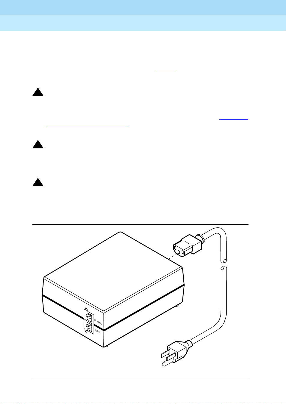
Use of 2 modular jacks. PHONE jack pins 7 and 8 (- and +, respectively)
provide power.
The PHONE and LINE jacks are 8-pin female nonkeyed 757-type jacks that can
accept D4, D7, and D8 modular plug cables. Figure 6
supply. The 1151A2 looks similar.
!
DANGER:
When operating power-supply equipment, you must follow basic safety
precautions to reduce the risk of fire, electric shock and personal injury.
Read, understand, and follow all warnings and instructions. See ‘‘Required
Safety Precautions’’ on page 7.
!
CAUTION:
Do not locate the unit within 7 in. (15.25 cm) of the floor.
555-233-116
Issue 1
April 2000
171151A and 1151A2 Power Supplies
shows a 1151A power
!
CAUTION:
Use the power supply
and in a controlled environment.
only
with telecommunications equipment, indoors,
pwr_sup1 CJL 051496
Figure 6. Typical 1151A Power Supply (Front)
Page 40

DEFINITY ECS Release 8.2
Installation for Adjuncts and Peripherals
Auxiliary Power Supplies
2
Desk Mounting
1. Place the power supply on a flat surface such as a desk.
Wall Mounting
1. For wall-mounting, use the keyhole slots on the bottom of the chassis.
Standards compliance
The 1151A and 1151A2 power supplies comply with the UL Standard UL 1459,
second edition.
Table 8. Standards compliance
Complies UL 1459
Certified CSA 22.2
555-233-116
Issue 1
April 2000
181151A and 1151A2 Power Supplies
Approved EN7950
Approved CE
Page 41

DEFINITY ECS Release 8.2
Installation for Adjuncts and Peripherals
Voice and Data Terminals and Extenders
3
555-233-116
Voice and Data Terminals and
Extenders
This chapter provides information on 2-wire voice and data terminals and
DEFINITY digital communication protocol (DCP) extenders.
Issue 1
April 2000
192-Wire DCP Endpoint
3
2-Wire DCP Endpoint
Wire the tip and ring connections of 2-wire DCP endpoints to a TN2224B digital
line 2-wire circuit pack (or equivalent) similar to the 2-wire analog endpoints for a
TN747B analog line circuit pack.
NOTE:
The TN2224B supports 2-wire DCP sets only (not 4-wire).
2-wire Voice Terminals
!
CAUTION:
Except for auxiliary power, if necessary, these should be the
connections to the modular wall jack. Do not bridge or parallel these
telephones.
Tab l e 9
provides the pin-out configuration for 2-wire voice terminals.
only
Page 42

DEFINITY ECS Release 8.2
Installation for Adjuncts and Peripherals
Voice and Data Terminals and Extenders
3
555-233-116
April 2000
Table 9. Pin-out for 2-wire Voice Terminals
Pin Number Function Pin Number Function
1 4-wire output from terminal 5 2-wire ring
2 4-wire output from terminal 7 4-wire input from system
3 4-wire input from system 7 Auxiliary power -48 VDC
4 2-wire tip 8 Auxiliary power GRD
2-Wire Voice and Data Terminals
Table 10 provides the pin-out configuration for 2-wire voice and data terminals.
Table 10. Pin-out for 2-wire Voice Terminals
Pin Number Function Pin Number Function
1 4-wire output from terminal 5 2-wire ring
Issue 1
202-Wire DCP Endpoint
2 4-wire output from terminal 7 4-wire input from system
3 4-wire input from system 7 Auxiliary power -48 VDC
4 2-wire tip 8 Auxiliary power GRD
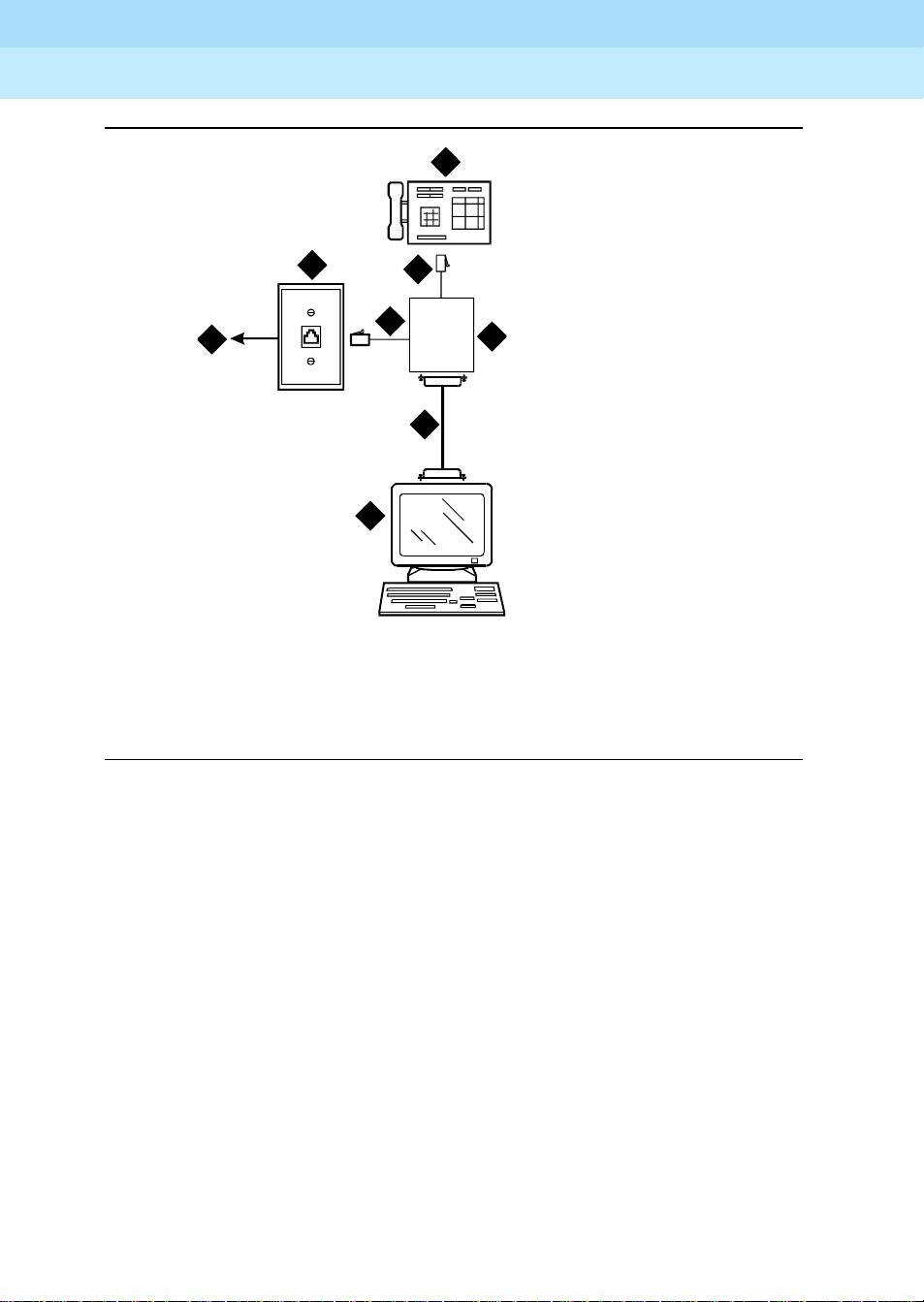
Figure 7 shows a workstation connecting to a data adapter. The line side of the
adapter connects to the TN2181 digital line 2-wire circuit pack via the main
distribution frame (MDF) (to the system cabinet).
Page 43
DEFINITY ECS Release 8.2
Installation for Adjuncts and Peripherals
Voice and Data Terminals and Extenders
3
555-233-116
2
Issue 1
April 2000
212-Wire DCP Endpoint
1
7
itdata RBP 032896
1. 103A or modular wall jack
2. 2-wire endpoint
3. Data terminal (serial data)
5
Phone
5
Line
6
3
4
I/O
5. 4-wire modular cord
6. 25-pair cable
7. To TN2181 digital line circuit pack
4. Data adapter (such as Italtel)
Figure 7. Typical Connections to a 2-Wire DCP Workstation
Wire the circuit pack to the MDF with a 25-pair cable:
1. Wire to the data adapter per local standards.
2. Wire the data terminal and telephone as instructed in the document
accompanying the data adapter.
Page 44

DEFINITY ECS Release 8.2
7
Installation for Adjuncts and Peripherals
Voice and Data Terminals and Extenders
3
555-233-116
DEFINITY DCP Extender, Stand Alone
The figure below shows a typical connection from a digital line 2-wire DCP circuit
pack through two DCP extender devices. See Appendix A, ‘‘Connector and
Cable Pinout Charts’’ for cabling information and pin assignments.
Issue 1
April 2000
22DEFINITY DCP Extender, Stand Alone
1
6
5
7
5
4
8
1. System cabinet
2. TN2181 or TN2224B circuit pack
3. 25-pair cable
4. DEFINITY DCP extender
5. Main distribution frame (MDF)
6. Public switched telephone network (PSTN)
3
10
9
4
2
cydfdcpe RPY 12309
7. 103A or modular wall jack
8. Modular line cord
9. DCP telephone (Such as 8410D,
8405, or 8434)
10. Remote work location
Figure 8. Typical DEFINITY DCP Extender Connections
Page 45

DEFINITY ECS Release 8.2
Installation for Adjuncts and Peripherals
Voice and Data Terminals and Extenders
3
555-233-116
DEFINITY DCP Extender, Rack Mount
Figure 9 shows a typical rack mount (multi-mount) DCP extender. Connections
from either a digital line 17-port 2-wire DCP circuit pack or a digital line 24-port 2wire DCP circuit pack, are made through two DCP extender devices. The stand
alone extender installs at the work location. To install the stand-alone unit, refer to
the installation instructions in ‘‘DEFINIT Y DCP Extender, Stand Alone’’
this chapter. Refer to Appendix A
Pinout’’. The DEFINITY Extender Switch Module System Administrator’s Guide
contains additional information.
, Tab le 35, ‘‘DCP Extender 25-Pair Cable
Issue 1
April 2000
23DEFINITY DCP Extender, Rack Mount
earlier in
h2dferm PDH 100796
1. Front of rack mount assembly
2. First circuit pack in slot 1 (“A”)
3. Slot 12 (“L”)
4. Rear of rack mount assembly
5. 25-pair connector to the MDF and the digital
line circuit packs
6. Power connector
Figure 9. Typical DEFINITY DCP Extender Connections
Page 46

DEFINITY ECS Release 8.2
Installation for Adjuncts and Peripherals
Voice and Data Terminals and Extenders
3
555-233-116
Issue 1
April 2000
24DEFINITY DCP Extender, Rack Mount
Page 47

DEFINITY ECS Release 8.2
Installation for Adjuncts and Peripherals
Data Modules and Asynchronous Data Units
4
555-233-116
Data Modules and Asynchronous
Data Units
Data modules connect peripheral equipment to the DEFINITY ECS or DEFINITY
ONE and convert between the RS-232 communications protocol used by
peripherals and the DEFINITY Digital Communications Protocol (DCP). Possible
peripherals include AUDIX adjunct equipment and terminals, serial printers,
customer-supplied terminals and host computers, call detail-recording (CDR)
devices, and pooled modems. The following data modules are described in this
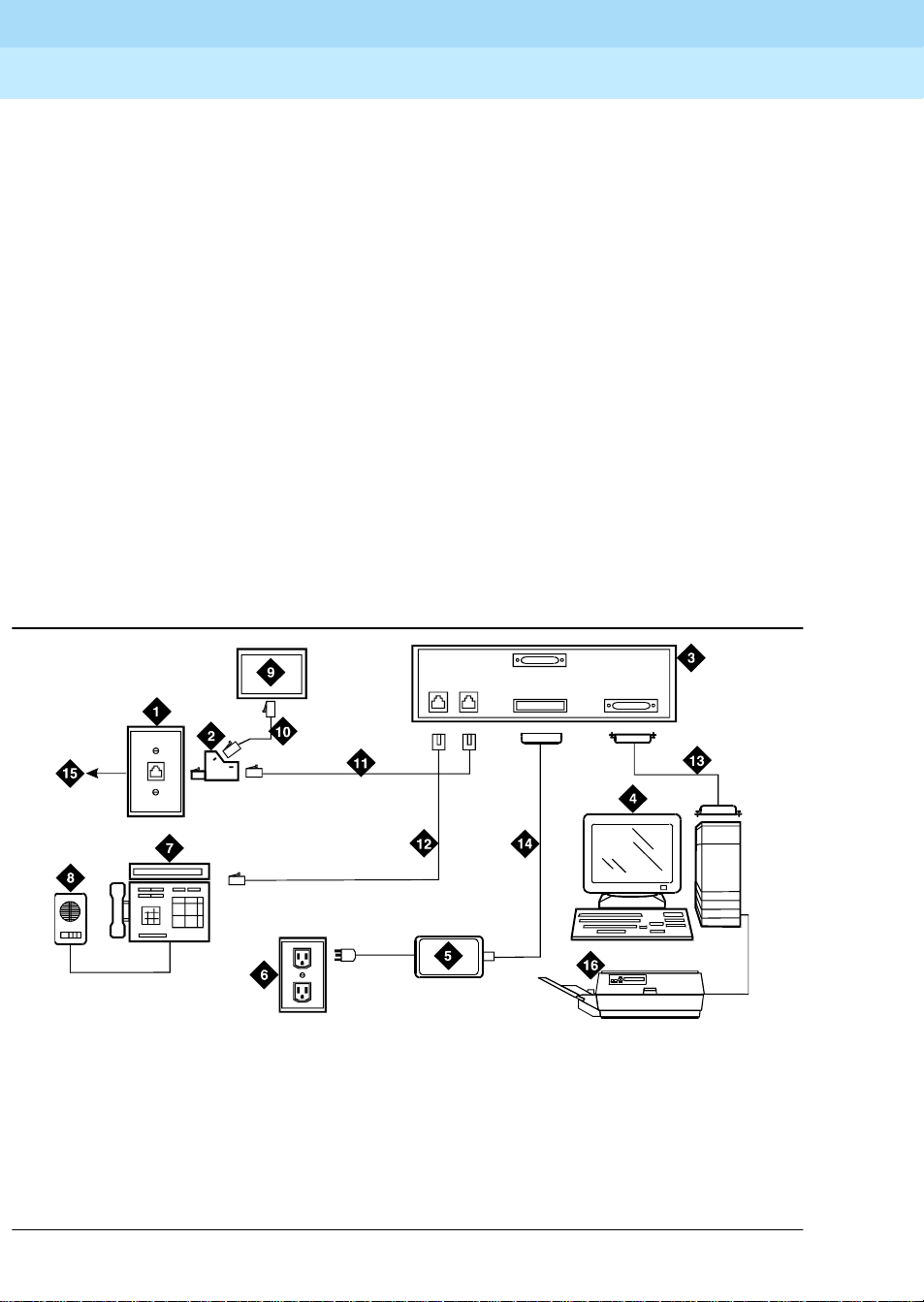
chapter, and Figure 10
shows typical data-module connections.
Issue 1
April 2000
25Understanding RS-232 communications
4
■
7400A/B/C/D
■
8400B
■
ExpressRoute 1000
■
Asynchronous data units (ADUs).
NOTE:
ISDN data modules, such as the 7500B, are not covered in this book. Refer
to Integrated Services Digital Network (ISDN) 7500B Data Module User’s
Manual, for detailed procedures. ISDN data modules connects DTE and
DCE equipment to the ISDN network using an RS-232 or V.35 interface and
an RS-377 automatic calling unit.
Understanding RS-232 communications
To install a data module, you have to set up the device to work with RS-232
devices.
Page 48
DEFINITY ECS Release 8.2
Installation for Adjuncts and Peripherals
Data Modules and Asynchronous Data Units
4
The RS-232 communications protocol defines a communications link as a Data
Communications Equipment (DCE) device and a Data Terminal Equipment (DTE )
device connected by an RS-232 cable. The send and receive pins on DCE
equipment (pins 2 and 3) are reversed on DTE equipment, so that the DCE
transmit pin connects to the receive pin of the DTE and vice versa.
Generally, the term DCE is applied to devices that mediate between customer
equipment and the carrier or network. Such devices include modems, data
modules, and data units. DTE describes devices that provide a user interface for
data commun ications , such as dumb terminals and PCs. When con figured as
DTE, data modules are used for asynchronous modem pooling. When configured
as DCE, data modules are analogous to modems in that they link a device such
as a terminal or PC (DTE) to DEFINITY.
To install a data module correctly, you identify the connected equipment as DCE
or DTE and do one of the following:
■
Configure the modem for a DTE or DCE connection
■
Install a null-modem converter
555-233-116
Issue 1
April 2000
26Understanding RS-232 communications
Detailed instructions are provided in the sections for each modem type (below).
cydfnst RPY 070397
1. 103A connector or modular wall jack
2. 400B2 adapter
3. Rear of data module (7400B Shown)
4. Host computer
5.Da ta module power supply
6. Electrical outlet
7. Display telephone
8. S101A speakerphone
Port 2
Phone
Line
Power Port 1
9. Auxiliary power supply for telephone
10. D7AP cord
11. D8W cord
12. Line to display telephone (D8W cord)
13. Data cable (EIA/RS -232)
14. Data-module power cable
15. To MDF and system cabinet
16. Printer
Figure 10. Typical Connections to a data module
Page 49

DEFINITY ECS Release 8.2
Installation for Adjuncts and Peripherals
Data Modules and Asynchronous Data Units
4
Installation Procedure
To install a typical data module, you perform the following tasks:
1. Obtain Required Equipment
2. Sett Hardware Options (must be completed before you administer or
physically connect the data module)
3. Connect Data Modules
4. Administer the DEFINITY ECS for Data Modules (can be completed either
before or after you physically connect the data module)
Obtain Required Equipment
To physically connect a data module to the system, you need the following parts.
■
105C/D Isolating Data Interface (if connecting to a DC cabinet)
■
EIA-232-D (RS-232-C) cable with a male connector (for the data module)
and the correct connector for the peripheral equipment
555-233-116
Issue 1
April 2000
27Installation Procedure
The cable connects the PC to the data module
■
Null-modem converter (optional)
■
V.35 cable with correct connectors (not required by all systems)
■
D8W telephone cord
The cord connects the data module’s LINE jack to the DEFINITY wall jack.
■
DCP telephone and D8W cord (optional)
The D8W cord connects the telephone to the data module’s PHONE jack.
■
Suitable auxiliary power supply if the optional telephone is installed (D7AP
power cord and 400B2 adapter in the US, international power supply,
suc h as the MSP-1, elsewhere).
You must have access to the administration console of the DEFINITY, either
through a terminal and keyboard or through a PC.
A breakout box for RS-232 interfaces may prove helpful in some cases. The RS232 breakout box helps you to identify the pin configuration of the RS-232
interface on the equipment you are trying to connect.
Sett Hardware Options
Depending on the data module, you may have to set various configuration
options using hardware switches, software commands, or both. You must set the
hardware options before you administer or physically install the data module.
Page 50

DEFINITY ECS Release 8.2
Installation for Adjuncts and Peripherals
Data Modules and Asynchronous Data Units
4
555-233-116
Setting 7400A Data-Module Hardware Options
Most configuration options are controlled by commands entered on the front
panel of the 7400A. But you have to make hardware changes when you want to
set up the 7400A data-module for use in a modem pool or as a piece of data
communications equipment. In a modem-pool, the data module operates as
data-terminal equipment (DTE). In most other applications, it functions as data
communications equipment (DCE). You have to set the correct operating mode
for the data module before you can access the menus for the remaining
configuration tasks.
To change the operating mode of the 7400A from DCE to DTE (or vice versa), you
change the position of a small circuit board (the Electronic Industries Association
connector board) inside the case. See Figure 11
!
WARNING:
Electrostatic discharge can severely damage sensitive electronic circuits.
Before handling any electronic hardware, be sure to wear a grounding wrist
strap or other static-dissipating device. Do not touch exposed circuitry or
semiconductor chips.
Issue 1
April 2000
28Sett Hardware Options
and proceed as follows.
1. Unplug the data module from the power receptacle.
2. Remove the access panel on the top of the case by grasping the rear lip
of the panel and pulling sharply upward.
3. While facing the front of the data module, locate the small EIA connector
circuit board. It sticks up vertically, and a large, silver arrow on the main
circuit board points to it.
Page 51

DEFINITY ECS Release 8.2
Installation for Adjuncts and Peripherals
Data Modules and Asynchronous Data Units
4
555-233-116
DTE
Issue 1
April 2000
29Sett Hardware Options
HOME
NEXT/NO BACK ENTER/YES
POWER TEST
7400A Data Module
1. 7400A data module 2. EIA connector board (shown in DTE mode)
Figure 11. Data Module Mode Selector
4. Note the three letters engraved in the upper lefthand corner of the EIA
connector board. Data modules ship from the factory with board inserted
with “DCE” in the upper left corner.
5. Use the DCE position to connect to DTE equipment. Use the DTE position
to connect to DCE equipment. To change the mode, remove the board by
gra spin g i t an d pu lli n g i t gent l y upwa r d . Fli p the bo a rd arou nd, l e f t to r i ght,
and reinsert it in the socket so that the correct operating mode, DCE or
DTE, appears in the upper lefthand corner.
6. Snap the top cover onto the unit.
Setting 7400B Data-Module Hardware Options
You configure the 7400B data module using DIP switches on the circuit card
inside the case. Figure 12
shows the front and rear of a 7400B data module.
DAT A
7400atop KLC 053096
Page 52

DEFINITY ECS Release 8.2
Installation for Adjuncts and Peripherals
Data Modules and Asynchronous Data Units
4
555-233-116
Issue 1
April 2000
30Sett Hardware Options
DATA
METERING
POWE R
TEST
PHONE
AA CD RD SD TR OH
7400B Data Mo du le
LINE
POW ER
CHECK
SPEED
DATA
PO RT 2
PORT 1
7400b RBP 032596
Figure 12. 7400B Data Module
To configure the 7400B data module, proceed as follows.
!
WARNING:
Electrostatic discharge can severely damage sensitive electronic circuits.
Before handling any electronic hardware, be sure to wear a grounding wrist
strap or other static-dissipating device. Do not touch exposed circuitry or
semiconductor chips.
1. If you are not attaching a telephone to the data module, activating data
metering, or enabling busyout on the local loop, you can use the factory
default settings. The 7400B data module is already configured for your
use. Stop now.
2. Otherwise, remove the access panel on the top of the case by grasping
the rear lip of the panel and pulling sharply upward.
3. Locate the DIP switch block, a bank of tiny switches on the circuit board,
in the center of the opening.
DIP switches 1, 5, and 8 control the attached telephone (if any), data
metering , and loopback on loc al loo p.
Page 53

DEFINITY ECS Release 8.2
Installation for Adjuncts and Peripherals
Data Modules and Asynchronous Data Units
4
4. Set the switches for the combination of options that you need to enable,
using the chart below as a guide.
No telephone attached, data metering OFF, busyout on local loop OFF
(factory default settings)
O
N123456789
DOWN DOWN DOWN DOWN DOWN DOWN DOWN DOWN DOWN
Telephone attached, data metering OFF, busyout on local loop OFF
O
N123456789
UP
DOWN DOWN DOWN DOWN DOWN DOWN DOWN DOWN
555-233-116
Issue 1
April 2000
31Sett Hardware Options
No telephone attached, data metering ON, busyout on local loop OFF
O
N123456789
UP
DOWN DOW N DOW N DOWN DOWN DOWN DOWN DOWN
No telephone attached, data metering OFF, busyout on local loop ON
O
N123456789
UP
DOWN DOW N DOW N DOWN DOWN DOWN DOWN DOWN
No telephone attached, data metering ON, busyout on local loop ON
O
N123456789
UP UP
DOWN DOW N DOW N DOWN DOWN DOWN DOWN
Page 54

DEFINITY ECS Release 8.2
Installation for Adjuncts and Peripherals
Data Modules and Asynchronous Data Units
4
Telephone attached, data metering ON, busyout on local loop OFF
O
N123456789
UP UP
DOWN DOWN DOWN DOWN DOWN DOWN DOW N
Telephone attached, data metering OFF, busyout on local loop ON
O
N123456789
UP UP
DOWN DOWN DOWN DOWN DOWN DOWN DOWN
Telephone attached, data metering ON, busyout on local loop ON
O
N123456789
555-233-116
Issue 1
April 2000
32Connect Data Modules
UP UP UP
DOWN DOWN DOWN DOWN DOWN DOWN
5. Replace the cover on the data module.
Connect Data Modules
To connect a single data module, follow the procedure in following section. To
connect multiple data modules, see Connecting Multiple Data Modules to the
System.
Page 55

DEFINITY ECS Release 8.2
Installation for Adjuncts and Peripherals
Data Modules and Asynchronous Data Units
4
Connecting a Single Data Module
!
CAUTION:
You must install a 105D or 105C isolating data interface adapter when
connecting data modules to equipment in DC-powered cabinets.
Connect the data module to your house wiring or DEFINITY as follows.
555-233-116
Issue 1
April 2000
33Connect Data Modules
1. Attach a D8W cable to the
LINE
port of the data module.
2. If you are going to attach a telephone to the data module
a. Attach a 400B2 adapter to the other end of the D8W cable.
b. Plug the adapter into a modular wall jack or 103A connector.
c. Plug a D7AP cord into the 400B2 adapter.
d. Plug the other en d of the D7AP cord into the auxiliary power supply
for the telephone.
You must have a separate power supply for the telephone and for
the data module.
e. Attach a D8W cable to the
PHONE
port of the data module.
3. If you are not attaching a telephone, attach the D8W cable from the Line
port of the data module to a modular wall jack or 103A connector.
4. Attach the data-module power supply to the power connector on the back
of the data module, and plug the power supply into an AC electrical outlet.
5. Connect an RS-232 cable to the
PORT 1
connector on the back of the
data module.
6. If the equipment includes a V.35 interface, plug a V.35 cable into the
V.35
connector on the data module.
7. If the data module is a 7400B DCE-only device and if the other end of the
cable is connected to another DCE device, insert a null-modem adapter
between the data module and the RS-232 cable.
8. Connect the other end of the RS-232 cable to a serial (COM) port
connection on the data device (host computer, serial printer, modem,
etc.).
9. Go to the configuration procedure for the data module you are using:
■
Installation Procedure
■
Configuring the 7400B Data Module
■
Configuring the 7400C HSL (High- Speed Link) Data Module
■
Configuring the 7400D Data Module
■
Configuring the 8400B Plus Data Module
■
Configuring the ExpressRoute 1000 Data Module
Page 56

DEFINITY ECS Release 8.2
Installation for Adjuncts and Peripherals
Data Modules and Asynchronous Data Units
4
555-233-116
Connecting Multiple Data Modules to the System
!
CAUTION:
You must install a 105D or 105C isolating data interface adapter when
connecting data modules to equipment in DC-powered cabinets.
You install multiple data modules in a data mounting on the DEFINITY. A Z77A
data mounting can take up to 8 data modules. See Figure 13
Issue 1
April 2000
34Connect Data Modules
.
1. Z77A data mounting
2. Data module (7400A shown)
3. Retaining bar
Figure 13. Z77A Data Mounting
Proceed as follows.
1. Set data-module hardware options before installing the hardware in the
mounting.
2. Release the horizontal retaining bar at the front of the data mounting by
pulling out the plungers at the left and right sides of the bar.
3. Pull the retaining bar out and down.
z77a KLC 053096
4. Retaining bar plunger
5. Twist-lock cable retainers
Page 57

DEFINITY ECS Release 8.2
Installation for Adjuncts and Peripherals
Data Modules and Asynchronous Data Units
4
4. Connect the a 25-pin RS-232 cable to the 25-pin connector on the rear of
the data module.
5. Route the cable through the data mounting and through the twist-lock
cable retainer on the top of the data mounting.
6. Attach the other end of the RS-232 cable to DTE or DCE .
7. Insert the data module vertically into the data mounting. Be sure the
display is to the top of the data mounting.
8. Repeat steps 2 through 5 for each data module.
9. Return the horizontal retaining bar to its original position to secure the data
modules inside the data mounting.
10. Go to the configuration procedure for the data module you are using:
■
Configuring the 7400A Data Module
■
Configuring the 7400B Data Module
■
Configuring the 7400C HSL (High- Speed Link) Data Module
■
Configuring the 7400D Data Module
555-233-116
Issue 1
April 2000
35Connect Data Modules
■
Configuring the 8400B Plus Data Module
Configuring the 7400A Data Module
The 7400A is a full-duplex, asynchronous data module for use with Digital
Communications Protocol (DCP). It is designed for applications that do not
require integration of voice and data. It supports asynchronous connections at
speeds up to 19.2 Kbps via an EIA-232-D interface. Figure 14
front and back of the 7400A data module.
represents the
Page 58
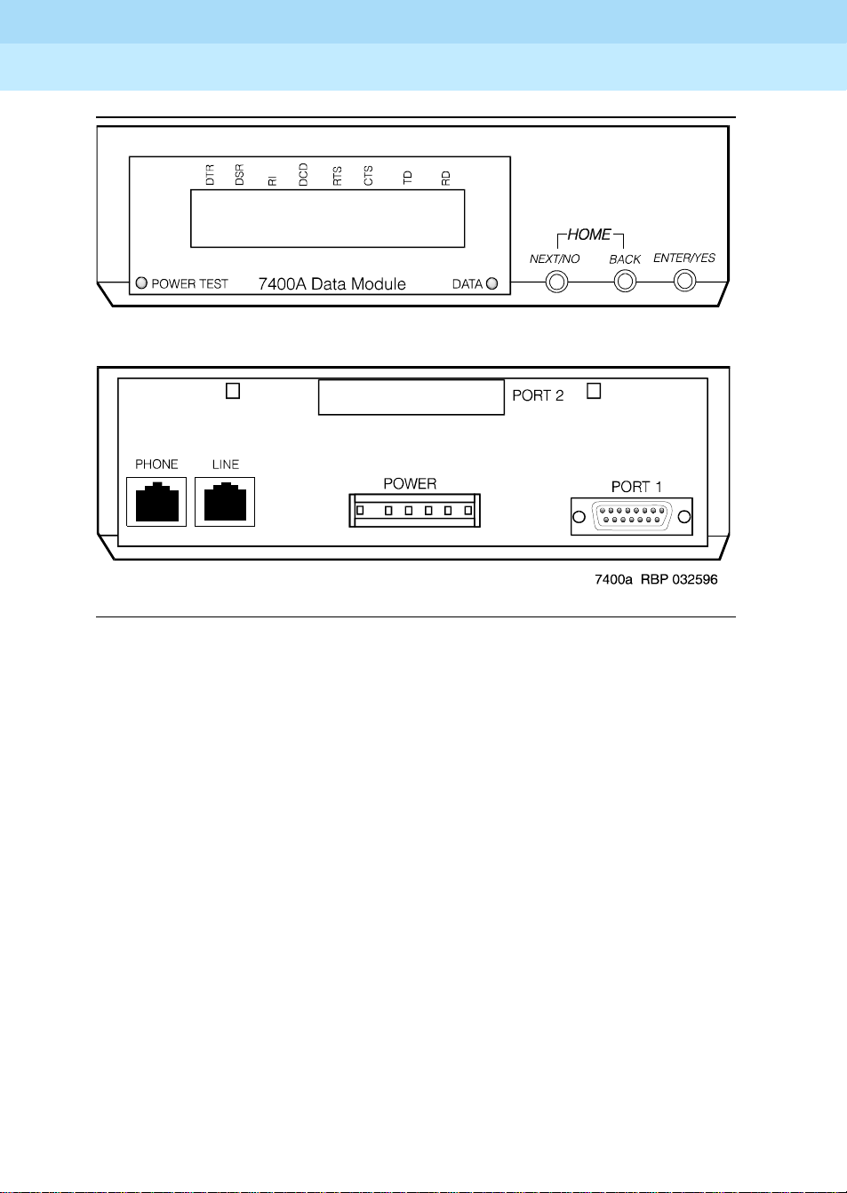
DEFINITY ECS Release 8.2
Installation for Adjuncts and Peripherals
Data Modules and Asynchronous Data Units
4
555-233-116
Issue 1
April 2000
36Connect Data Modules
Figure 14. 7400A asynchronous data module
Using the 7400A menu system
On the 7400A, you select communications settings using the controls on the front
panel of the device . An LCD displays the configuration menus. You use the
NEXT/NO
YES
button to select values.
and
BACK
buttons to navigate through the menus and the
Powering up the 7400A
When you power up the 7400A, the
the 7400A data module displays the HOME screen on the LCD. The figure below
represents a typical home screen. Dashes indicate a lead that is connected,
ovals a lead that is not.
POWER TEST
and
DA TA
LEDs light up, and
ENTER/
Page 59

DEFINITY ECS Release 8.2
Installation for Adjuncts and Peripherals
Data Modules and Asynchronous Data Units
4
D
POWER
TEST
✹
D
T
SRR
R
00—0 0 0 ——
D
C
I
D
7400A Data Module
Adjusting the control-panel display on the 7400A
1. Adjust the contrast of the display so that you can see it comfortably. Press
ENTER/YES
the
settings.
button. This steps you through the available contrast
555-233-116
R
C
T
TSTDR
S
Issue 1
April 2000
37Connect Data Modules
D
DATA
HOME
NEXT/NO BACK ENTER/YES
✹ ❍❍❍
00—000——
DATA
NEXT/NO BACK ENTER/YES
● ❍❍➜ ●
Push the button indicated by the arrow (➜)
7400A data module, EIA RS-232 interface circuits
The data module communicates with other equipment via a configurable, 25-pin
RS-232 serial interface. DCE and DTE operation use different sets of pins and
assign different functions to some of the same pins. To avoid confusion later on,
please take a moment to review the differences. See the table below (the pins
most discussed in subsequent sections have been emphasized).
Pin Name Function DCE DTE
1 — Not used — —
2 BA (TD) Transmitted Data Input Output
3 BB (RD) Received Data Output Input
4 CA (RTS) Request to Send Input Output
5 CB (CTS) Clear to Send Output Input
6 CC (DSR) Data Communication Equipment Ready Output Input
7 AB (SG) Signal Ground Common Common
8 CF (RLSD) Received Line Signal Detector Output Input
Continued on next page
Page 60

DEFINITY ECS Release 8.2
Installation for Adjuncts and Peripherals
Data Modules and Asynchronous Data Units
4
555-233-116
Issue 1
April 2000
38Connect Data Modules
Pin Name Function DCE DTE
9 — Reserved for Testing +12 volts —
10 — Reserved for Testing -12 volts —
11 — Not used — —
12 CI Data Signal Rate Select (DCE Source) Output Input
13 CI2 Data Signal Rate Select 2 (DCE Source) — Input
14 — Not used — —
15 DB* Transmitter Signal Element Timing (DCE
Output Input
Source)
16 — Not used — —
17 DD* Receiver Signal Element Timing (DCE
Output Input
Source)
18 LL Local Loopback Input Output
19 CH2 Data Signal Rate Select 2 (DTE Source) — Output
20 CD (DTR) Data Terminal Equipment Ready Input Output
21 RL Remove Loopback Input Output
22 CE (RI) Ring Indicator Output Input
23 CH Data Signal Rate Select (DTE Source) Input Output
24 DA* Transmit Signal Element Timing (DTE
Input Output
Source)
25 TM Test Mode Output Input
Continued on next page
* Circuits are not used for asynchronous operation. Outp uts are clamped OFF and inputs are ignored.
Configuring the 7400A for data communications
equipment (DCE) applications
If you are not going to use the 7400A data module in a modem pool, proceed as
follows.
Page 61

DEFINITY ECS Release 8.2
Installation for Adjuncts and Peripherals
Data Modules and Asynchronous Data Units
4
Setting interface options on 7400A DCE
555-233-116
Issue 1
April 2000
39Connect Data Modules
1. To access the menus, press the
00—0 0 0 ——
Push the button indicated by the arrow (➜)
2. When the
NO
button.
SET OPTIONS?
SET OPTIONS?
prompt appears on the LCD. Press the
Push the button indicated by the arrow (➜)
3. The
VIEW OPTIONS?
VIEW OPTIONS?
prompt appears. Press the
Push the button indicated by the arrow (➜)
NEXT/NO
DATA
● ❍❍➜ ●
DATA
●➜ ● ❍ ❍
DATA
●➜ ● ❍ ❍
button.
NEXT/NO BACK ENTER/YES
NEXT/NO BACK ENTER/YES
NEXT/NO
NEXT/NO BACK ENTER/YES
button.
NEXT/
You will return to the options menus in a minute. But first you must select a
command interface for the data module.
4. The
SET INTERFACE?
SET INTERFACE?
prompt appears. Press the
DATA
ENTER/YES
NEXT/NO BACK ENTER/YES
button.
● ❍❍➜ ●
Push the button indicated by the arrow (➜)
INT =
A series of
InterfaceType
?
prompts appears.
Page 62

DEFINITY ECS Release 8.2
Installation for Adjuncts and Peripherals
Data Modules and Asynchronous Data Units
4
555-233-116
Issue 1
April 2000
40Connect Data Modules
5. F or each prompt, if you want to sele ct the interface, press the
button or, if you want a different interface, press the
NEXT/NO
a. Enable the answer-only interface if the data module must operate
DATA
NEXT/NO BACK ENTER/YES
without any kind of external control:
INT=ANS ONLY?
● ❍❍ ❍
Select an option (NEXT/NO or ENTER/YES)
b. Enable the AT-command interface if users need to control the data
module remotely, using a dial-up connection and Hayescompatible modem commands:
INT = AT COM?
DATA
NEXT/NO BACK ENTER/YES
● ❍❍ ❍
Select an option (NEXT/NO or ENTER/YES)
c. E nable the keyboard-dial interface if users need to control the data
module interactively, from a terminal:
ENTER/YES
button.
INT = KYBD DIAL?
DATA
NEXT/NO BACK ENTER/YES
● ❍❍ ❍
Select an option (NEXT/NO or ENTER/YES)
After you select an interface, the data module runs a self-test and returns
to the HOME screen.
D
POWER
TEST
✹
D
T
SRR
R
00—0 0 0 ——
D
R
C
C
T
I
D
7400A Data Module
TSTDR
S
D
DATA
HOME
NEXT/NO BACK ENTER/YES
✹ ❍❍❍
Page 63

DEFINITY ECS Release 8.2
Installation for Adjuncts and Peripherals
Data Modules and Asynchronous Data Units
4
Setting speed options on 7400A DCE
555-233-116
Issue 1
April 2000
41Connect Data Modules
1. Press the
00—0 0 0 ——
Push the button indicated by the arrow (➜)
2. The
SET OPTIONS?
button.
SET OPTIONS?
Push the button indicated by the arrow (➜)
A series of
3. Press the
Then press the
NEXT/NO
SET
number
NEXT/NO
ENTER/YES
button to continue with the setup procedure.
DATA
NEXT/NO BACK ENTER/YES
●➜ ● ❍ ❍
prompt appears on the LCD. Press the
DATA
NEXT/NO BACK ENTER/YES
ENTER/YES
● ❍❍➜ ●
SPEED?
button until you see the
prompts appears.
SET 9600 SPEED?
prompt.
button.
SET 9600 SPEED?
DATA
NEXT/NO BACK ENTER/YES
● ❍❍➜ ●
Push the button indicated by the arrow (➜)
Most DEFINITY connections operate at the 9600 speed.
4. The
9600 = ON?
9600=ON?
prompt appears. Press the
DATA
ENTER/YES
NEXT/NO BACK ENTER/YES
● ❍❍➜ ●
Push the button indicated by the arrow (➜)
5. The
CONTINUE?
CONTINUE?
prompt appears. Press the
DATA
ENTER/YES
NEXT/NO BACK ENTER/YES
● ❍❍➜ ●
Push the button indicated by the arrow (➜)
button .
button.
Page 64

DEFINITY ECS Release 8.2
Installation for Adjuncts and Peripherals
Data Modules and Asynchronous Data Units
4
555-233-116
Issue 1
April 2000
42Connect Data Modules
6. The
SET 19200 SPEED?
SET 19200 SPEED?
prompt appears. Press the
DATA
NEXT/NO BACK ENTER/YES
NEXT/NO
button.
●➜ ● ❍ ❍
Push the button indicated by the arrow (➜)
7. If you selected the A T-command interface in the section ‘‘Setting interface
options on 7400A DCE’’ (above), you are finished configuring the 7400A
data module.
Setting the automatic-answer feature on 7400A DCE
You can set up the 7400A data module to automatically answer calls or you can
have it ignore calls until an operator answers manually. Set up the data module
for automatic answering unless specifically directed to otherwise.
1. When the
button.
SET ANSWER?
Push the button indicated by the arrow (➜)
SET ANSWER?
prompt appears, press the
DATA
NEXT/NO BACK ENTER/YES
● ❍❍➜ ●
ENTER/YES
2. When the
answering, press the
ANS = AUTO?
ENTER/YES
prompt appears, if you want to enable automatic
button. Otherwise, press the
button.
ANS = AUTO?
DATA
NEXT/NO BACK ENTER/YES
● ❍❍ ❍
Select an option (NEXT/NO or ENTER/YES)
3. If you pressed
NEXT/NO
in the preceding step, the
ANS —> MANUAL?
prompt appears. If you want to disable automatic answering, press the
ENTER/YES
ANS —> MANUAL?
button. Otherwise, press the
DATA
NEXT/NO
NEXT/NO BACK ENTER/YES
button.
● ❍❍ ❍
Select an option (NEXT/NO or ENTER/YES)
NEXT/NO
Page 65

DEFINITY ECS Release 8.2
Installation for Adjuncts and Peripherals
Data Modules and Asynchronous Data Units
4
555-233-116
Issue 1
April 2000
43Connect Data Modules
4. The
CONTINUE?
CONTINUE?
prompt appears. Press the
DATA
ENTER/YES
NEXT/NO BACK ENTER/YES
button.
● ❍❍➜ ●
Push the button indicated by the arrow (➜)
Setting the break-disconnect option on 7400A DCE
This setting specifies the length of the BREAK signal, a string of 10 or more
spaces that tells the host that the user needs to interrupt operations. There are
three options: TRIPLE, LONG (the default), and NONE. Accept the default
values, unless otherw is e ins tr ucted.
1. When the
button to keep the default.
SET BREAK DISC?
SET BREAK DISC?
prompt appears, press the NEXT/NO
DATA
●➜ ● ❍ ❍
Push the button indicated by the arrow (➜)
NEXT/NO BACK ENTER/YES
Configuring the RS-232 interface on 7400A DCE
You can set each pin of the RS-232 cable to meet the needs of specific
applications or connected equipment. however, in most cases, you can use the
defaults.
To set the EIA leads, proceed as follows:
1. When the
button to keep the default or the
SET
LeadName
LEAD?
prompt appears, press the
ENTER/YES
SET
LeadName
LEAD?
DATA
●➜ ● ❍ ❍
Push the button indicated by the arrow (➜)
NEXT/NO
button to make a change.
NEXT/NO BACK ENTER/YES
Page 66

DEFINITY ECS Release 8.2
Installation for Adjuncts and Peripherals
Data Modules and Asynchronous Data Units
4
555-233-116
Issue 1
April 2000
44Connect Data Modules
2. If you pressed the
prompt, the
LeadName
ENTER/YES
-> ON?
button at the
prompt appears. Press the
SET
LeadName
LEAD?
ENTER/YES
button.
LeadName
-> ON?
DATA
NEXT/NO BACK ENTER/YES
● ❍ ❍➜ ●
Push the button indicated by the arrow (➜)
3. Repeat until all leads have been set.
Setting parity on 7400A DCE
Next you need to identify the type of parity coding that the data module should
expect. Parity is an error-detection scheme that is based on the value of a parity
bit in each unit of information. Four coding schemes are used:
MARK
, and
SPACE
. In odd-parity coding, the parity bit is set to 0 if the number
of 1s in the information is odd, 1 if it is even. In even-parity coding, the parity bit
is set to 0 if the number of 1s in the information is even, 1 if it is odd. Mark-parity
coding always sets the parity bit to 1. Space-parity coding always sets the parity
bit to 0.
1. Accept the default value, unless otherwise instructed. When the
PARITY?
SP ACE
prompt appears, press the NEXT/NO button to keep the default,
.
ODD, EVEN
SET
,
SET PARITY?
DATA
NEXT/NO BACK ENTER/YES
●➜ ● ❍ ❍
Push the button indicated by the arrow (➜)
Enabling remote loopback testing on 7400A DCE
You can set the remote loopback option to
GRANT
1. Accept the default value, unless otherwise instructed. When the
REMOTE LOOP?
default,
GRANT
SET REMOTE LOOP?
prompt appears, press the NEXT /NO button to keep the
.
DATA
●➜ ● ❍ ❍
Push the button indicated by the arrow (➜)
DENY
or
NEXT/NO BACK ENTER/YES
.
SET
Page 67

DEFINITY ECS Release 8.2
Installation for Adjuncts and Peripherals
Data Modules and Asynchronous Data Units
4
Configuring the ring indicator on 7400A DCE
555-233-116
Issue 1
April 2000
45Connect Data Modules
The ring-indicator (pin 22) setting can have either of two values:
CYCLE
or ON
(the default).
1. Accept the default values, unless otherwise instructed. When the
LEAD?
prompt appears, press the NEXT/NO button to keep the default,
SET RI
ON.
SET RI LEAD?
DATA
NEXT/NO BACK ENTER/YES
●➜ ● ❍ ❍
Push the button indicated by the arrow (➜)
Enabling remote loopback on 7400A DCE
The remote-loopback setting (pin 21) can have either of two values: ON or
(the default).
1. Accept the default values, unless otherwise instructed. When the
LEAD?
ON
.
SET RL LEAD?
prompt appears, press the
NEXT/NO
DATA
button to keep the default,
NEXT/NO BACK ENTER/YES
●➜ ● ❍ ❍
Push the button indicated by the arrow (➜)
SET RL
OFF
Setting the signals-disconnect (SIGLS DISC) option on 7400A DCE
The settings can have either of two values: ON (the default) or
Accept the default values, unless otherwise instructed.
1. When the
SET SIGLS DISC?
pr ompt appea rs, pre ss t he
to keep the default, ON.
SET SIGLS DISC?
DATA
NEXT/NO BACK ENTER/YES
●➜ ● ❍ ❍
Push the button indicated by the arrow (➜)
OFF
.
NEXT/NO
button
Page 68

DEFINITY ECS Release 8.2
Installation for Adjuncts and Peripherals
Data Modules and Asynchronous Data Units
4
Enabling test mode on 7400A DCE
555-233-116
Issue 1
April 2000
46Connect Data Modules
The test-mode (pin 25) setting can have either of two values: ON or
default).
1. Accept the default values, unless otherwise instructed. When the
LEAD?
ON
.
SET TM LEAD?
prompt appears, press the
NEXT/NO
DATA
button to keep the default,
NEXT/NO BACK ENTER/YES
●➜ ● ❍ ❍
Push the button indicated by the arrow (➜)
Exiting menus and saving changes on 7400A DCE
DONE?
DONE?
prompt appears, press the
DATA
1. When the
Push the button indicated by the arrow (➜)
2. When the SAV E CHANGES? prompt appears, press the
button.
ENTER/YES
NEXT/NO BACK ENTER/YES
button.
● ❍ ❍➜ ●
ENTER/YES
OFF
(the
SET TM
SAVE CHANGES?
Push the button indicated by the arrow (➜)
Your change s are saved.
CHANGES SAVED
Push the button indicated by the arrow (➜)
DATA
NEXT/NO BACK ENTER/YES
● ❍ ❍➜ ●
DATA
NEXT/NO BACK ENTER/YES
● ❍ ❍➜ ●
Page 69

DEFINITY ECS Release 8.2
Installation for Adjuncts and Peripherals
Data Modules and Asynchronous Data Units
4
You return HOME.
D
POWER
TEST
●
D
T
SRR
R
———0————
D
C
I
D
7400A Data Module
Checking DEFINITY administration on 7400A DCE
Check that the DEFINITY is administered to support the 7400A data module in
the DCE application as follows:
1. If necessary, return to the HOME display on the 7400A by pressing the
NEXT/NO
and
BACK
555-233-116
R
C
T
TSTDR
S
D
DATA
● ❍❍❍
buttons at the same time.
Issue 1
April 2000
47Connect Data Modules
HOME
NEXT/NO BACK ENTER/YES
2. From the HOME display, press
displayed, then press the
3. If you see the message
ENTER/YES
WAITING
NEXT/NO
button.
DISCONNECTED
...
ANS/ORIG CALL?
until
, the switch has not
been administered correctly.
4. If you see the message
DIAL TONE
followed by
DISCONNECT CALL?
the DEFINITY is correctly administered for the 7400A data module. Press
ENTER/YES
the
The 7400A replies
ORIG CALL?
5. Return to the HOME display by pressing the
button to return to the menu.
WAITING
DISCONNECTED
...
menu.
and returns to the
NEXT/NO
and
BACK
at the same time.
Configuring the 7400A for modem pooling (DTE) applications
From the HOME screen, proceed as follows.
Setting speed options on 7400A DTE
1. To access the menus, press the
NEXT/NO
button.
is
ANS/
buttons
,
Page 70

DEFINITY ECS Release 8.2
Installation for Adjuncts and Peripherals
Data Modules and Asynchronous Data Units
4
555-233-116
Issue 1
April 2000
48Connect Data Modules
2. When the
YES
POWER
TEST
●
Push the button indicat ed b y the arrow (➜)
A series of
3. Press the
Then press the
SET OPTIONS?
button.
D
D
T
SRR
R
SET OPTIONS?
D
C
I
D
7400A Data Module
SET
number
NEXT/NO
ENTER/YES
SET 9600 SPEED?
R
T
S
button until you see the
Push the button indicated by the arrow (➜)
prompt appears on the LCD, press the
C
TSTDR
D
DATA
HOME
NEXT/NO BACK ENTER/YES
● ➜ ● ❍ ❍
SPEED?
prompts appears.
SET 9600 SPEED?
button.
DATA
NEXT/NO BACK ENTER/YES
● ❍❍➜ ●
ENTER/
prompt.
Most DEFINITY connections operate at the 9600 speed.
4. The
9600 = OFF?
9600=OFF?
prompt appears. Press the
DATA
NEXT/NO
NEXT/NO BACK ENTER/YES
●➜ ● ❍ ❍
Push the button indicated by the arrow (➜)
5. The
9600 —> ON?
9600 —> ON?
prompt appears. Press the
DATA
ENTER/YES
NEXT/NO BACK ENTER/YES
●❍❍➜ ●
Push the button indicated by the arrow (➜)
button.
button.
Page 71

DEFINITY ECS Release 8.2
Installation for Adjuncts and Peripherals
Data Modules and Asynchronous Data Units
4
555-233-116
Issue 1
April 2000
49Connect Data Modules
6. The
CONTINUE?
CONTINUE?
prompt appears. Press the
DATA
ENTER/YES
NEXT/NO BACK ENTER/YES
●❍❍➜ ●
Push the button indicated by the arrow (➜)
7. The
SET 19200 SPEED?
prompt appears. Press the
keep the default.
SET 19200 SPEED?
DATA
NEXT/NO BACK ENTER/YES
●➜ ● ❍ ❍
Push the button indicated by the arrow (➜)
8. The
SET AT CONTROL?
prompt appears. Press the
to enable Hayes-compatible modem commands. Press the
button to accept the default (OFF).
SET AT CONTROL?
DATA
NEXT/NO BACK ENTER/YES
● ❍ ❍ ❍
Select an option (NEXT/NO or ENTER/YES)
button.
NEXT/NO
button to
ENTER/YES
NEXT/NO
button
Use the AT CONTROL setting to let users control the data module
remotely, using a dial-up connection.
9. If you enabled AT commands, the
NEXT/NO
button.
AT=OFF?
AT = OFF?
DATA
prompt appears. Press the
NEXT/NO BACK ENTER/YES
●➜ ● ❍ ❍
Push the button indicated by the arrow (➜)
Page 72

DEFINITY ECS Release 8.2
Installation for Adjuncts and Peripherals
Data Modules and Asynchronous Data Units
4
555-233-116
Issue 1
April 2000
50Connect Data Modules
10. If you enabled A T commands, the
ENTER/YES
AT —> ON?
button.
AT —> ON?
DATA
prompt appears. Press the
NEXT/NO BACK ENTER/YES
● ❍❍➜ ●
Push the button indicated by the arrow (➜)
11. If you enabled AT commands, the
ENTER/YES
the
CONTINUE?
button.
CONTINUE?
DATA
NEXT/NO BACK ENTER/YES
prompt appears. Press
●❍❍➜ ●
Push the button indicated by the arrow (➜)
Configuring the RS-232 interface on 7400A DTE
You can set each pin of the RS-232 cable to meet the needs of specific
applications, though in most cases, the defaults should work. For a list of pins
and leads, see Table 11
below.
The Data Signal-Rate Select EIA leads—
CI, CI2, CH, and CH2—of the RS-232
cable indicate the receive/transmit speeds that the data module can use.
the EIA signal-rate leads, proceed as follows:
From the
1.
Then press the
SET OPTIONS?
display, press NEXT/NO until SET OPTIONS?
HOME
ENTER/YES
button.
DATA
NEXT/NO BACK ENTER/YES
appears.
●❍❍➜ ●
Push the button indicated by the arrow (➜)
2. When the
CI LEAD?
SET 300 SPEED?
prompt appears,
appears. Then, using the table and instructions below as a
press NEXT/NO until SET
guide, start setting the leads.
SET CI LEAD?
DATA
NEXT/NO BACK ENTER/YES
●❍❍➜ ●
Push the button indicated by the arrow (➜)
To set
Page 73

DEFINITY ECS Release 8.2
Installation for Adjuncts and Peripherals
Data Modules and Asynchronous Data Units
4
Table 11. DTE-mode RS-232 signal-rate lead settings for the 7400A
If you selecte d AT cont r ol in an e ar li er step, set OFF OFF OFF OFF
You want only 1 data speed. OFF OFF OFF OFF
You want 2 data speeds. ON ON OFF OFF
You want only 3 or 4 data speeds. ON ON ON ON
555-233-116
Issue 1
April 2000
51Connect Data Modules
CI CH CI2 CH2
3. When the
SET CI LEAD?
keep the default (OFF) or the
SET CI LEAD?
Choose a button indicated by the question mark (?)
4. If you pressed
ENTER/YES
prompt appears, press the
selection.
CI LEAD=ON?
Push the button indicated by the arrow (➜)
5. W h en t he
SET CI2 LEAD?
keep the default (OFF) or the
prompt appears, press the NEXT/NO
ENTER/YES
button to make a change.
DATA
NEXT/NO BACK ENTER/YES
● ● ? ❍ ● ?
in the preceding step and the
ENTER/YES
button again to confirm your
DATA
NEXT/NO BACK ENTER/YES
CI LEAD = ON?
●❍❍➜ ●
prompt appe ars , press the
ENTER/YES
button to make a change.
NEXT/NO
button to
button to
SET CI2 LEAD?
DATA
NEXT/NO BACK ENTER/YES
● ● ? ❍ ● ?
Choose a button indicated by the question mark (?)
Page 74

DEFINITY ECS Release 8.2
Installation for Adjuncts and Peripherals
Data Modules and Asynchronous Data Units
4
555-233-116
Issue 1
April 2000
52Connect Data Modules
6. If you pressed
CI2 LEAD = ON?
ENTER/YES
prompt appears press the
confirm your selection.
CI2 LEAD=ON?
Push the button indicated by the arrow (➜)
7. When the
SET CH LEAD?
keep the default (OFF) or the
SET CH LEAD?
Choose a button indicated by the question mark (?)
8. If you pressed
ON?
pr ompt appears , press th e
ENTER/YES
selection.
in the preceding step and the
ENTER/YES
DATA
NEXT/NO BACK ENTER/YES
●❍❍➜ ●
pr ompt appe ars, pr ess th e
ENTER/YES
button to make a change.
DATA
NEXT/NO BACK ENTER/YES
● ● ? ❍ ● ?
in the preceding step and the
ENTER/YES
button again to confirm your
button again to
NEXT/NO
button to
CH LEAD =
CH LEAD=ON?
Push the button indicated by the arrow (➜)
9. If the
SET CH2 LEAD?
keep the default (OFF) or the
SET CH2 LEAD?
Choose a button indicated by the question mark (?)
DATA
NEXT/NO BACK ENTER/YES
●❍❍➜ ●
prompt appears, press the
ENTER/YES
button to make a change.
DATA
NEXT/NO BACK ENTER/YES
● ● ? ❍ ● ?
NEXT/NO
button to
Page 75

DEFINITY ECS Release 8.2
Installation for Adjuncts and Peripherals
Data Modules and Asynchronous Data Units
4
10. The maintenance-option EIA leads configure loopback testing for the data
module. You do not need to set any specific options. So, when the
LEAD?
pr ompt appears, press the
to return HOME.
555-233-116
NEXT/NO
and
BACK
buttons together
Issue 1
April 2000
53Connect Data Modules
SET LL
SET LL LEAD?
DATA
NEXT/NO BACK ENTER/YES
●➜ ●➜ ● ❍
Push the button indicated by the arrow (➜)
11. When the
SAV E CHANGES?
prompt appears, press the
ENTER/YES
button.
SAVE CHANGES?
DATA
NEXT/NO BACK ENTER/YES
●❍❍➜ ●
Push the button indicated by the arrow (➜)
CHANGES SA VED
The
message flashes on screen, and you return to the
HOME screen. The data module is now configured.
Restoring factory defaults on 7400A DTE
If necessary, you can always revert to the factory default settings. From the
HOME screen, proceed as follows.
1. To access the menus, press the
NEXT/NO
button.
00—0 0 0 ——
Push the button indicated by the arrow (➜)
2. When the
NO
button.
SET OPTIONS?
Push the button indicated by the arrow (➜)
SET OPTIONS?
DATA
NEXT/NO BACK ENTER/YES
●➜ ● ❍ ❍
prompt appears on the LCD, press the
DATA
NEXT/NO BACK ENTER/YES
●➜ ● ❍ ❍
NEXT/
Page 76

DEFINITY ECS Release 8.2
Installation for Adjuncts and Peripherals
Data Modules and Asynchronous Data Units
4
555-233-116
Issue 1
April 2000
54Connect Data Modules
3. When the
NO
button.
VIEW OPTIONS?
Push the button indicated by the arrow (➜)
4. When the
ENTER/YES
TEST - RESET?
Push the button indicated by the arrow (➜)
5. When the
NEXT/NO
DATA LOOPBACK?
Push the button indicated by the arrow (➜)
VIEW OPTIONS?
TEST - RESET?
prompt appears on the LCD, press the
prompt appears on the LCD, press the
button.
DATA LOOPBACK?
button.
NEXT/
DATA
NEXT/NO BACK ENTER/YES
●➜ ● ❍ ❍
DATA
NEXT/NO BACK ENTER/YES
● ❍ ❍ ➜ ●
prompt app ear s on the LCD, press the
DATA
NEXT/NO BACK ENTER/YES
●➜ ● ❍ ❍
6. When the
button.
SELF - TEST?
Push the button indicated by the arrow (➜)
7. When the
NEXT/NO
LOCAL LOOPBACK?
Push the button indicated by the arrow (➜)
SELF-TEST?
prompt appears on the LCD, press the
LOCAL LOOPBACK?
button.
NEXT/NO
DATA
NEXT/NO BACK ENTER/YES
●➜ ● ❍ ❍
prompt appears on the LCD, press the
DATA
NEXT/NO BACK ENTER/YES
●➜ ● ❍ ❍
Page 77
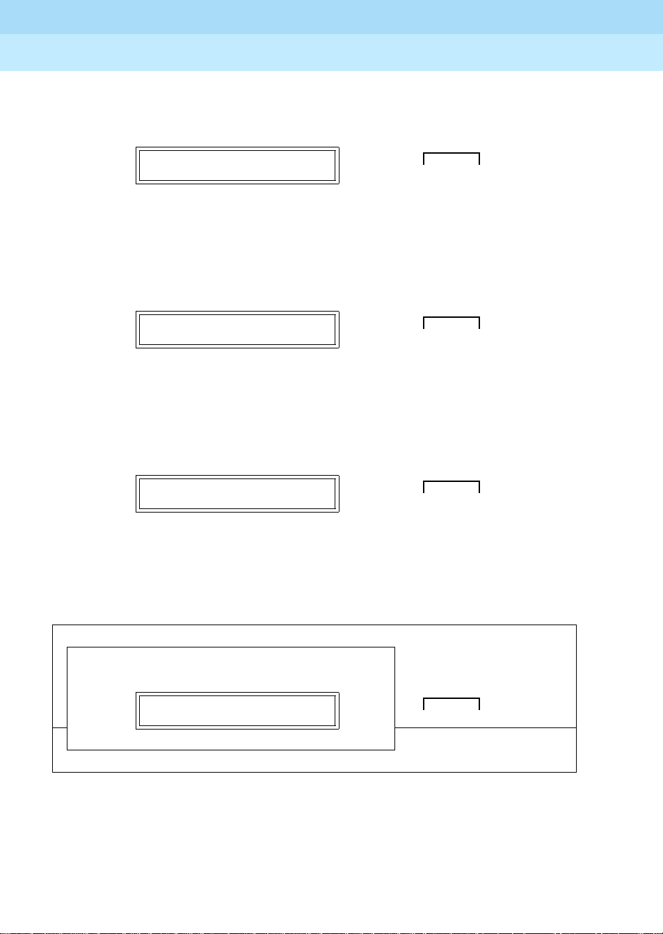
DEFINITY ECS Release 8.2
Installation for Adjuncts and Peripherals
Data Modules and Asynchronous Data Units
4
555-233-116
Issue 1
April 2000
55Connect Data Modules
8. When the
NEXT/NO
LOCAL LOOP/ST?
Push the button indicated by the arrow (➜)
9. When the
NEXT/NO
REMOTE LOOPBACK?
Push the button indicated by the arrow (➜)
10. When the
ENTER/YES
RESET OPTIONS?
Push the button indicated by the arrow (➜)
LOCAL LOOP/ST?
prompt appears on the LCD, press the
button.
REMOTE LOOPBACK?
button.
RESET OPTIONS?
prompt appears on the LCD, press the
button.
DATA
NEXT/NO BACK ENTER/YES
●➜ ● ❍ ❍
prompt appears on the LCD, press the
DATA
NEXT/NO BACK ENTER/YES
●➜ ● ❍ ❍
DATA
NEXT/NO BACK ENTER/YES
● ❍ ❍ ➜ ●
The factory options are restored, and you return to the HOME screen.
D
POWER
TEST
●
D
T
SRR
R
00—0 0 0 ——
D
R
C
I
7400A Data Module
T
D
S
Configuring the 7400B Data Module
The factory default settings for the7400B data module are generally satisfactory.
But if you need to change them, you use a terminal device and the AT command
language commonly used by Hayes-compatible modems (7400B data modules
C
TSTDR
D
DATA
HOME
NEXT/NO BACK ENTER/YES
● ❍❍❍
Page 78

DEFINITY ECS Release 8.2
Installation for Adjuncts and Peripherals
Data Modules and Asynchronous Data Units
4
have no control buttons). While a full explanation of the Hayes command set is
beyond the scope of this book, the following sections sketch the basic processes
involved in changing the factory settings.
Installing required configuration equipment for the 7400B
Before you can enter AT configuration commands, you must first connect a
terminal or a PC with a keyboard, monitor, and terminal-emulation software to the
data module. Pr oceed as follows.
1. Connect one end of an RS-232 cable to an RS-232, serial-communications
port (often called a COM port) on the terminal or PC.
2. Connect the other end of the RS-232 cable to Port 1 of the data module
3. If you are using a PC, start your terminal emulation software.
Selecting command mode on the 7400B
When it is transmitting and receiving data, the 7400B data module is online, in
data mode. To configure the 7400B, you have to switch it to command mode.
Proceed as follows.
555-233-116
Issue 1
April 2000
56Connect Data Modules
1. From the terminal keyboard, enter the escape sequence:
+++
The data module enters command mode and displ ays the OK result code.
Displaying the current configuration on the 7400B
1. Enter
at&v
Enabling automatic answering on the 7400B
where
ats0=
nnn
nnn
is a decimal number in the range 1-255
.
1. Enter
Enabling remote operation on the 7400B
The exact configuration of any particular 7400B data module depends on what it
is being used for. Consult a list of Hayes-compatible AT commands to see what
is possible. The following is an example of a typical, custom configuration.
The 7400B Data Module can be used at a remote site as a dedicated service
device to answer incoming data calls, send data to a remote end device, and
then hang up. For example, you might wish to provide access to a printer from a
remote site. The following is a typical command line you might use for setting up
this operation (spaces are used here for readability, but are not required):
1. at &c1 &d2 q1 s0=1 &w0 &y0
where:
■ at
puts the modem in command mode
Page 79

DEFINITY ECS Release 8.2
Installation for Adjuncts and Peripherals
Data Modules and Asynchronous Data Units
4
555-233-116
Issue 1
April 2000
57Connect Data Modules
■ &C1
sets the Data Carrier Detect (DCD) circuit of the data module
to operate according to the EIA standard
■ &D2
sets the data module to go on hook when an on-to-off
transition is detected on the Data Terminal Ready (DTR) input,
disconnecting the call
■ Q1
turns off the result codes that would be the normal responses of
the data module to commands that it receives.
■ S0=1
turns on the automatic answer feature and causes the data
module to answer an incoming data call on the first ring
■ &W0
■ &Y0
causes the current configuration to be stored in profile
selects the configuration stored in profile 0 to become the
current configuration each time the data module is powered on
Configuring the 7400B for remote administration
1. At the command prompt of your terminal-emulation software or terminal,
at&c1&d2&s1s0=1&w0&w1&y0
enter
where:
■ at
puts the modem in command mode
■ &c1
■ &d2
tells the modem to respond to DCD
tells the modem to respond to DTR
0
■ &s1
■ s0=1
■ &w0
■ &w1
■ &y0
tells the modem to respond to DSR
tells the modem to auto answer on the first ring
tells the modem to save changes in profile
tells the modem to save changes in profile
tells the modem to use profile0 after a power failure
Restoring factory defaults for the 7400B
1. Enter
at&F
Exiting command mode on the 7400B
After configuring the 7400B, exit command mode, and put the data module back
online.
1. Enter O (capital O).
Configuring the 7400C HSL (HighSpeed Link) Data Module
Figure 15 shows the front and rear of a 7400C synchronous data module.
0
1
Page 80

DEFINITY ECS Release 8.2
Installation for Adjuncts and Peripherals
Data Modules and Asynchronous Data Units
4
555-233-116
Issue 1
April 2000
58Connect Data Modules
Figure 15. 7400C Data Module (High Speed Link)
Setting the data speed for the 7400C
Proceed as follows.
1. From the HOME screen, press the
OPTS?
appears. Then press the
SET DATA OPTS?
Push the button indicated by the arrow (➜)
2. When SET SPEED?
SET SPEED?
appears, press the
Push the button indicated by the arrow (➜)
NEXT/NO
ENTER/YES button.
DATA
● ❍ ❍ ➜ ●
ENTER/YES button.
DATA
● ❍ ❍ ➜ ●
button until
NEXT/NO BACK ENTER/YES
NEXT/NO BACK ENTER/YES
SET DATA
Page 81

DEFINITY ECS Release 8.2
Installation for Adjuncts and Peripherals
Data Modules and Asynchronous Data Units
4
555-233-116
Issue 1
April 2000
59Connect Data Modules
The current transmission speed appears:
default) or
SPEED = 64KBPS?
3. To keep the existing speed, press the
SPEED = 56 KBPS?
SPEED = 56KBPS?
ENTER/YES button.
DATA
● ❍ ❍➜ ●
Push the button indicated by the arrow (➜)
4. To change the existing speed, press NEXT/NO
SPEED = 56 KBPS?
DATA
●➜ ● ❍ ❍
Push the button indicated by the arrow (➜)
When the
SPEED ->
NewSpeed
?
pr ompt appears, pres s the
button.
(the
NEXT/NO BACK ENTER/YES
.
NEXT/NO BACK ENTER/YES
ENTER/YES
SPEED -> 64 KBPS?
DATA
NEXT/NO BACK ENTER/YES
● ❍ ❍➜ ●
Push the button indicated by the arrow (➜)
5. The CONTINUE?
CONTINUE?
prompt appears. Press the
DATA
ENTER/YES
NEXT/NO BACK ENTER/YES
button.
●❍❍➜ ●
Push the button indicated by the arrow (➜)
6. If you want to set any other options, skip to the following section.
7. Otherwise, if you want to quit now, press
Then press the
DONE?
ENTER/YES button.
NEXT/NO until DONE?
DATA
NEXT/NO BACK ENTER/YES
●❍❍➜ ●
Push the button indicated by the arrow (➜)
appears.
Page 82

DEFINITY ECS Release 8.2
Installation for Adjuncts and Peripherals
Data Modules and Asynchronous Data Units
4
555-233-116
Issue 1
April 2000
60Connect Data Modules
8. When
SAVE CHANGES?
SAVE CHANGES?
appear s, press the
DATA
ENTER/YES button again.
NEXT/NO BACK ENTER/YES
●❍❍➜ ●
Push the button indicated by the arrow (➜)
CHANGES SAVED
appears, and the data module returns to the HOME
screen.
Setting other data options for the 7400C
You can usually use the default settings for all other options. However, two
exceptions are discussed below.
Selecting data inversion for 64-kbps, HDLC transmissions on restricted
facilities
Data inversion is available when you are transmitting at 64 kbps over restricted
facilities using HDLC-based protocols. Proceed as follows.
1. If you need compatibility with an ACCUNET MP DM, set
to ON using the menus and controls as described above, in ‘‘Setting the
data speed for the 7400C’’.
DA T A INVERSION
2. Otherwise, set
DATA INVERSION
to
OFF
.
3. Exit and save changes, as described above, in ‘‘Setting the data speed for
the 7400C’’.
Configuring the 7400C for a dedicated private line
The factory default settings assume that the data module connects to a switched,
dial-up line. Private lines are permanent, unswitched connections, so they have
to be specially configured. Proceed as follows.
1. Set the dialing method to
described above, in ‘‘Setting the data speed for the 7400C’’
2. Set the answering mode (
3. Set the
4. Set the
5. Set
DTR
lead to
DSR
lead to ON.
PERMANENT CONNECTION
6. Exit and save changes, as described above, in ‘‘Setting the data speed for
the 7400C’’.
MANUAL,
ANS
IGNORE
.
using the menus and controls as
AUTO
) to
to
YES
.
.
.
Page 83

DEFINITY ECS Release 8.2
Installation for Adjuncts and Peripherals
Data Modules and Asynchronous Data Units
4
Configuring the 7400D Data Module
The 7400D data module is a converted 7400A used for synchronous data
transmission (Figure 16
). It is a direct replacement for the MPDM. You configure
the 7400D just as you would a 7400A, except that there is no SET INTERFACE
option (the 7400D is an answer-only device that cannot originate calls). It
supports DCE mode only. DTE modem-pooling is not supported. The PHONE
and PORT2 connectors are not used.
The following table lists recommended settings for a typical installation. For the
configuration procedure, see the subsequent sections.
Recommended settings for typical configurations
The table below summarizes the recommended configuration values for the
7400D data module. The procedures for setting these values follow.
Options CMS settings DCS settings
300 OFF OFF
555-233-116
Issue 1
April 2000
61Connect Data Modules
1200 OFF OFF
2400 OFF OFF
4800 OFF OFF
9600 ON (OFF for R8r) ON
19200 OFF (ON for R8r) OFF
ANSWER AUTO AUTO
CI OFF ON
CH LEAD OFF OFF
CTS LEAD NORMAL NORMAL
DCD LEAD NORMAL ON
DSR LEAD NORMAL ON
DTR DETECT 50 MSEC 50 MSEC
DTR LEAD FOLLOW IGNORE
RI LEAD ON ON
SIGLS DISC ON ON
TM LEAD OFF OFF
Continued on next page
Page 84

DEFINITY ECS Release 8.2
Installation for Adjuncts and Peripherals
Data Modules and Asynchronous Data Units
4
555-233-116
Issue 1
April 2000
62Connect Data Modules
Figure 16. 7400D Data Module
Accessing the menus of the 7400D
You configure the 7400D from a set of menus.
1. To access the menus, press the
00—0 0 0 ——
Push the button indicated by the arrow (➜)
2. When the
NO
button.
SET OPTIONS?
SET OPTIONS?
Push the button indicated by the arrow (➜)
NEXT/NO
prompt appears on the LCD. Press the
button.
DATA
NEXT/NO BACK ENTER/YES
●➜ ● ❍ ❍
NEXT/
DATA
NEXT/NO BACK ENTER/YES
●➜ ● ❍ ❍
Page 85

DEFINITY ECS Release 8.2
Installation for Adjuncts and Peripherals
Data Modules and Asynchronous Data Units
4
555-233-116
Issue 1
April 2000
63Connect Data Modules
3. The
VIEW OPTIONS?
VIEW OPTIONS?
prompt appears. Press the
DATA
NEXT/NO
NEXT/NO BACK ENTER/YES
button.
●➜ ● ❍ ❍
Push the button indicated by the arrow (➜)
Setting speed options for the 7400D
The data speed depends on the exact application, but most require 9600 bps or,
less commonly, 19200.
1. Press the
2. The
button.
NEXT/NO
00—0 0 0 ——
button to continue with the setup procedure.
DATA
●➜ ● ❍ ❍
Push the button indicated by the arrow (➜)
SET OPTIONS?
prompt appears on the LCD. Press the
NEXT/NO BACK ENTER/YES
ENTER/YES
SET OPTIONS?
Push the button indicated by the arrow (➜)
A series of
3. Press the
SET
NEXT/NO
prompt. Then press the
SET
yourSpeed
Push the button indicated by the arrow (➜)
number
SPEED?
prompts appears.
button until you see the
ENTER/YES
SPEED?
DATA
NEXT/NO BACK ENTER/YES
● ❍❍➜ ●
SET
yourSpeed
SPEED?
button.
DATA
NEXT/NO BACK ENTER/YES
● ❍❍➜ ●
Page 86

DEFINITY ECS Release 8.2
Installation for Adjuncts and Peripherals
Data Modules and Asynchronous Data Units
4
555-233-116
Issue 1
April 2000
64Connect Data Modules
4. Press the
Then press the
NEXT/NO
yourSpeed
button until you see the
ENTER/YES
=ON?
button.
DATA
yourSpeed
NEXT/NO BACK ENTER/YES
=ON?
prompt.
● ❍❍➜ ●
Push the button indicated by the arrow (➜)
5. If the
CONTINUE?
CONTINUE?
prompt appears, press the
DATA
ENTER/YES
NEXT/NO BACK ENTER/YES
button.
● ❍❍➜ ●
Push the button indicated by the arrow (➜)
Setting the automatic-answer feature on the 7400D
You can set up the 7400A data module to automatically answer calls or you can
have it ignore calls until an operator answers manually. Set up the data module
for automatic answering unless specifically directed to otherwise.
1. When the
button.
SET ANSWER?
prompt appears, press the
ENTER/YES
SET ANSWER?
DATA
NEXT/NO BACK ENTER/YES
● ❍❍➜ ●
Push the button indicated by the arrow (➜)
2. When the
ANS = AUTO?
prompt appears, press the
ENTER/YES
button
for most applications.
ANS = AUTO?
DATA
NEXT/NO BACK ENTER/YES
● ❍❍➜ ●
Push the button indicated by the arrow (➜)
Configuring the RS-232 interface of the 7400D
Fr om the front panel, you can set each pin of the RS-232 cable to meet the needs
of specific applications, though in most cases, the settings below should work.
Page 87

DEFINITY ECS Release 8.2
Installation for Adjuncts and Peripherals
Data Modules and Asynchronous Data Units
4
555-233-116
Issue 1
April 2000
65Connect Data Modules
1. When the
SET CI LEAD?
Push the button indicated by the arrow (➜)
2. P r e ss the
correctSetting
CI =
Push the button indicated by the arrow (➜)
3. When the
CONTINUE?
Push the button indicated by the arrow (➜)
SET CI LEAD?
NEXT/NO
correctSetting
button until you see the
?
prompt. Then press the
CONTINUE?
prompt appears, press the
DATA
● ❍❍➜ ●
CI =
ENTER/YES
?
DATA
● ❍ ❍➜ ●
prompt appears, press the
DATA
●❍❍➜ ●
ENTER/YES
NEXT/NO BACK ENTER/YES
correctSetting
button.
?
CI ->
or
button.
NEXT/NO BACK ENTER/YES
ENTER/YES
NEXT/NO BACK ENTER/YES
button.
4. When the
button.
SET CH LEAD?
Push the button indicated by the arrow (➜)
5. P r e ss the
correctSetting
>
CH =
Push the button indicated by the arrow (➜)
6. When the
SET CH LEAD?
NEXT/NO
correctSetting
button until you see the
?
prompt. Then press the
?
CONTINUE?
prompt appears, press the
DATA
NEXT/NO BACK ENTER/YES
● ❍❍➜ ●
CH =
ENTER/YES
DATA
NEXT/NO BACK ENTER/YES
●❍❍➜ ●
prompt appears, press the
ENTER/YES
correctSetting
button.
ENTER/YES
?
CH -
or
button.
Page 88

DEFINITY ECS Release 8.2
Installation for Adjuncts and Peripherals
Data Modules and Asynchronous Data Units
4
555-233-116
Issue 1
April 2000
66Connect Data Modules
7. When the
button.
SET CTS LEAD?
Push the button indicated by the arrow (➜)
8. Press the
CTS ->
correctValue
CTS ->
Push the button indicated by the arrow (➜)
9. When the
10. When the
button.
SET CTS LEAD?
NEXT/NO
correctValue
CONTINUE?
button until you see the
?
prompt. Then press the
?
prompt appears, press the
SET DCD LEAD?
prompt appears, press the
DATA
NEXT/NO BACK ENTER/YES
●❍❍➜ ●
CTS =
correctValue
ENTER/YES
DATA
NEXT/NO BACK ENTER/YES
●❍❍➜ ●
ENTER/YES
prompt appears, press the
ENTER/YES
?
button.
button.
ENTER/YES
or
SET DCD LEAD?
Push the button indicated by the arrow (➜)
11. Press the
DCD ->
correctValue
DCD =
Push the button indicated by the arrow (➜)
12. When the
NEXT/NO
correctValue
button until you see the
CONTINUE?
DATA
NEXT/NO BACK ENTER/YES
●❍❍➜ ●
DCD =
?
prompt. Then press the
?
DATA
NEXT/NO BACK ENTER/YES
●❍❍➜ ●
prompt appears, press the
correctValue
ENTER/YES
ENTER/YES
?
button.
button.
or
Page 89

DEFINITY ECS Release 8.2
Installation for Adjuncts and Peripherals
Data Modules and Asynchronous Data Units
4
555-233-116
Issue 1
April 2000
67Connect Data Modules
13. When the
button.
SET DSR LEAD?
Push the button indicated by the arrow (➜)
14. Pr ess the
correctValue
->
DSR ->
Push the button indicated by the arrow (➜)
15. When the
16. When the
button.
SET DSR LEAD?
NEXT/NO
correctValue
button until you see the
?
prompt. Then press the
CONTINUE?
prompt appears, press the
?
prompt appears, press the
SET DTR DETECT?
ENTER/YES
DATA
NEXT/NO BACK ENTER/YES
●❍❍➜ ●
DSR =
ENTER/YES
DATA
correctValue
button.
NEXT/NO BACK ENTER/YES
●❍❍➜ ●
ENTER/YES
prompt appears, press the
?
DSR
or
button.
ENTER/YES
SET DTR DETECT?
Push the button indicated by the arrow (➜)
17. Press the
DTR ->
or
button.
DTR =
Push the button indicated by the arrow (➜)
18. When the
NEXT/NO
button until you see the
correctValue
correctValue
MSEC?
CONTINUE?
DATA
NEXT/NO BACK ENTER/YES
●❍❍➜ ●
DTR =
MSEC?
prompt. Then press the
DATA
NEXT/NO BACK ENTER/YES
●❍❍➜ ●
prompt appears, press the
correctValue
ENTER/YES
ENTER/YES
MSEC?
button.
Page 90

DEFINITY ECS Release 8.2
Installation for Adjuncts and Peripherals
Data Modules and Asynchronous Data Units
4
555-233-116
Issue 1
April 2000
68Connect Data Modules
19. When you see the
button.
SET DTR LEAD?
Push the button indicated by the arrow (➜)
DTR =
NEXT/NO
?
prompt appears. Then press the
correctValue
20. Press the
correctValue
>
Push the button indicated by the arrow (➜)
21. When the
22. When the
CONTINUE?
SET LL LEAD?
skip this setting.
SET DTR LEAD?
prompt, press the
DATA
●❍❍➜ ●
button until the
?
DTR =
DATA
● ❍ ❍ ➜ ●
prompt appears, press the
prompt appears, press the
ENTER/YES
NEXT/NO BACK ENTER/YES
correctValue
NEXT/NO BACK ENTER/YES
?
DTR -
or
ENTER/YES
ENTER/YES
NEXT/NO
button.
button.
button to
SET LL LEAD?
Push the button indicated by the arrow (➜)
23. When the
to skip this setting.
SET LL DETECT?
Push the button indicated by the arrow (➜)
24. When the
SET RI LEAD?
Push the button indicated by the arrow (➜)
SET LL DETECT?
SET RI LEAD?
prompt appears, press the
DATA
NEXT/NO BACK ENTER/YES
●➜ ● ❍ ❍
prompt appears, press the
DATA
NEXT/NO BACK ENTER/YES
●➜ ● ❍ ❍
ENTER/YES
DATA
NEXT/NO BACK ENTER/YES
●❍❍➜ ●
NEXT/NO
button
button.
Page 91

DEFINITY ECS Release 8.2
Installation for Adjuncts and Peripherals
Data Modules and Asynchronous Data Units
4
555-233-116
Issue 1
April 2000
69Connect Data Modules
25. Press the
correctValue
>
SET RI = ON?
Push the button indicated by the arrow (➜)
26. When the
27. When the
skip this setting.
SET RL LEAD?
Push the button indicated by the arrow (➜)
28. When the
button.
NEXT/NO
CONTINUE?
SET RL LEAD?
button until the
?
prompt appears. Then press the
prompt appears, press the
prompt appears, press the
SET SIGLS DISC?
RI =
correctValue
?
ENTER/YES
DATA
NEXT/NO BACK ENTER/YES
●❍❍➜ ●
ENTER/YES
NEXT/NO
DATA
NEXT/NO BACK ENTER/YES
●➜ ● ❍ ❍
prompt appears, press the
RI -
or
button.
button.
button to
ENTER/YES
SET SIGLS DISC?
Push the button indicated by the arrow (➜)
29. Press the
SIGLS DISC ->
YES
button .
SIGLS DISC = ON?
Push the button indicated by the arrow (➜)
30. When the
NEXT/NO
button until the
correctValue
CONTINUE?
DATA
NEXT/NO BACK ENTER/YES
●❍❍➜ ●
SIGLS DISC =
?
prompt appears. Then press the
DATA
NEXT/NO BACK ENTER/YES
●❍❍➜ ●
prompt appears, press the
correctValue
ENTER/YES
?
or
ENTER/
button.
Page 92

DEFINITY ECS Release 8.2
Installation for Adjuncts and Peripherals
Data Modules and Asynchronous Data Units
4
555-233-116
Issue 1
April 2000
70Connect Data Modules
31. When the
SET TM LEAD?
button.
SET TM LEAD?
Push the button indicated by the arrow (➜)
32. Press the
NEXT/NO
appears, then press the
TM = OFF?
Push the button indicated by the arrow (➜)
33. When the
DONE?
DONE?
Push the button indicated by the arrow (➜)
prompt appears, press the
DATA
●❍❍➜ ●
button until the
ENTER/YES
TM = OFF?
button.
DATA
●❍❍➜ ●
prompt appears, press the
DATA
●❍❍➜ ●
ENTER/YES
NEXT/NO BACK ENTER/YES
TM -> OFF?
or
NEXT/NO BACK ENTER/YES
ENTER/YES
NEXT/NO BACK ENTER/YES
button.
prompt
34. When the
SAV E CHANGES?
button.
SAVE CHANGES?
Push the button indicated by the arrow (➜)
CHANGES SA VED
The
message flashes on screen, and you return to the
HOME screen. The data module is now configured.
Configuring the 8400B Plus Data Module
Figure 17 shows the rear of a 8400B plus asynchronous data module. The unit
provides integrated voice and data communications over standard, 2-wire,
twisted-pair circuits within 2000 ft. of a DEFINITY. The unit can emulate a Hayescompatible interface for standard personal computer (PC) communication. The
options for the 8400B Plus are set from the rear panel interface. Refer to
DEFINITY Communications System User’s Guide for procedures.
prompt appears, press the
DATA
NEXT/NO BACK ENTER/YES
●❍❍➜ ●
ENTER/YES
Page 93

DEFINITY ECS Release 8.2
Installation for Adjuncts and Peripherals
Data Modules and Asynchronous Data Units
4
555-233-116
Issue 1
April 2000
71Connect Data Modules
PHONE
LINE
POWER
8400b RBP 041196
Figure 17. 8400B Plus Data Module
Installing required configuration equipment for the 8400B
Before you can enter configuration commands, you must first connect a terminal
or a PC with a keyboard, monitor, and terminal-emulation software to the data
module. Proceed as follows.
1. Connect one end of an RS-232 cable to an RS-232, serial-communications
port (often called a COM port) on the terminal or PC.
2. Connect the other end of the RS-232 cable to Port 1 of the data module
3. If you are using a PC, start your terminal emulation software.
Selecting 8400B options
On the 8400B data module, all configuration options are enabled by default. You
configure the 8400B by disabling options with a code that you enter in a memory
register (S24) in the data module. Consult the table below, and perform the steps
that follow.
Table 12. Codes for disabling default settings of the 8400B data module
Default setting Disabling code
With Telephone
US Companding
Telephone Provides Dialin g
Disable Data Metering Feature
Immediate Speakerphone Activation
Automatic Speakerphone Activation
Disable Busyout During Local Loopback Test
1
2
4
16
32
64
128
Continued on next page
Proceed as follows.
Page 94

DEFINITY ECS Release 8.2
Installation for Adjuncts and Peripherals
Data Modules and Asynchronous Data Units
4
1. Calculate an option-selection value using Figure 12, ‘‘Codes for disabling
default settings of the 8400B data module’’. Add up the disabling codes
for all options that you wish to disable.
555-233-116
Issue 1
April 2000
72Connect Data Modules
For example, if you turned off
Data Metering Feature
1 + 2 + 16 = 19
With T elephone, US Companding, Disable
, the selection code would be:
2. Check the current data-module setting by entering
3. If the current value does not match the selection value you calculated,
ATS24=
enter
nnn
, where
nnn
is the selection value you calculated.
Configuring the ExpressRoute 1000 Data Module
You can substitute an ExpressRoute 1000 data module for the 8400B data
module. Both DCP and ISDN-BRI connections are possible. Figure 18
typical connections.
!
CAUTION:
In DC-powered cabinet installations, a 105C Isolator adapter is required
when connecting equipment to a data module.
ATS24?
.
shows
Page 95
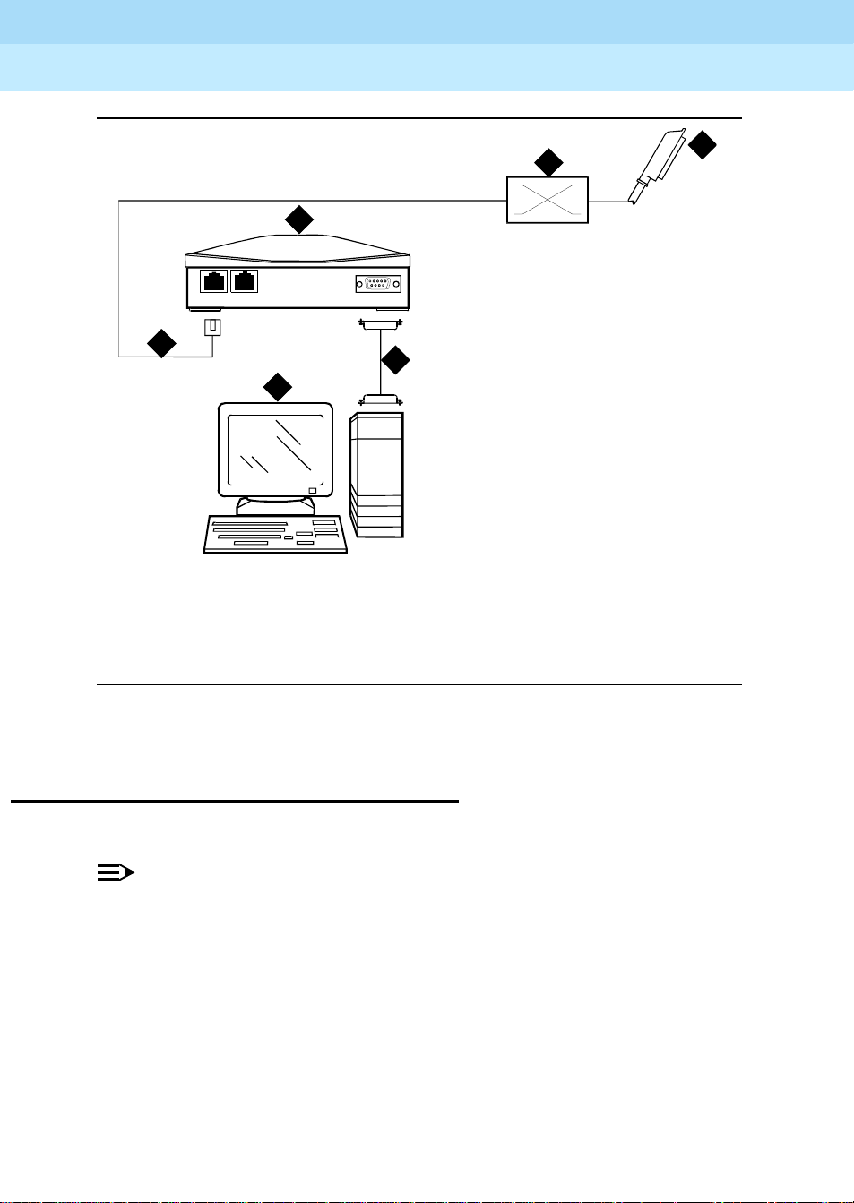
DEFINITY ECS Release 8.2
Installation for Adjuncts and Peripherals
Data Modules and Asynchronous Data Units
4
555-233-116
Issue 1
April 2000
73Administer the DEFINITY ECS for Data Modules
3
LINE
PHONE
POWER
5
4
6
1. To BRI circuit pack or DCP digital
line circuit pack
2. Main distribution frame (MDF)
3. ExpressRoute 1000 data module
2
1
cydf008 RPY 123097
4. PC administration terminal
5. Modular line cord
6. M25B (25-Pin RS-232) cable
Figure 18. Typical ExpressRoute 1000 Data Module Connections
Administer the DEFINITY ECS for Data Modules
You have to administer each data module that you attach to the system.
NOTE:
Only the basic procedure is covered here. For the full range of options, see
the DEFINITY Enterprise Communications Server Release 8 Administrator’s
Guide.
1. Loc ate an avail able port. At the DEFINITY ECS admi ni strat ion console,
enter
list config port
Page 96

DEFINITY ECS Release 8.2
Installation for Adjuncts and Peripherals
Data Modules and Asynchronous Data Units
4
555-233-116
Screen 1. Typical system-configuration listing
Issue 1
April 2000
74Administer the DEFINITY ECS for Data Modules
2. Locate an unassigned port on a suitable circuit pack, and make a note of
the corresponding port number.
T he port number is the
cabinet number,
C
is the single-character carrier identifier, and SS is the
Board Number
UUCSS
,
2-digit slot number) followed by the next 2-digit number,
sequence in the
UUCSSPP
Assigned Ports
.
fields at the right side of the form:
(where UU is the 2-digit
PP
, in the
For example, in the listing above, the next available port address for the
TN2181 digital line circuit pack would be
01A0503
.
3. Fr om the DEFINITY administration console, open a new data-module form
by typing
add data-module next
The system automatically assigns the next available extension number to
the data module.
Page 97

DEFINITY ECS Release 8.2
Installation for Adjuncts and Peripherals
Data Modules and Asynchronous Data Units
4
Screen 2. Typical data-module form
555-233-116
Issue 1
April 2000
75Asynchronous Data Units (ADUs)
step 2
Port
field, enter the s ev e n-digit port address that you w r o te down in
, abov e.
4. In the
5. If you installed a telephone on the data module, enter the extension
number and station name for this telephone in the
part of the form.
6. Press the
F3 key to close the form and save the changes.
Asynchronous Data Units (ADUs)
ADUs are used with Data Line circuit packs to connect peripherals, such as
printers, data terminals, fax equipment, and call-detail recording equipment to
the DEFINITY. Figure 19
■
Add a female-to-male EIA-232 cable (shown) to make a Z3A1 ADU
assembly.
■
Add a female-to-female EIA-232 cable (not shown) to make a Z3A4 ADU
assembly.
shows a typical Z3A2 ADU assembly (without a cable).
ASSIGNED MEMBER
Page 98

DEFINITY ECS Release 8.2
Installation for Adjuncts and Peripherals
Data Modules and Asynchronous Data Units
4
555-233-116
1. Z3A2 ADU
2. 25-pin male D-connector (EIA-232-D) to
DTE
3. Wall jack connector (to data line circuit
pack or analog line circuit pack or
equivalent)
Issue 1
April 2000
76Asynchronous Data Units (ADUs)
adu KLC053196
4. Telephone jack (to analog telephone)
5. Originate/disconnec t jack
6. Female connector on EIA-232-D cable
7. Male connector on EIA-232-D cable
Figure 19. Z3A2 Asynchronous Data Unit (ADU)
Refer to the tables in Appendix A, ‘‘Connector and Cable Pinout Charts’’
pinouts of the TN726B data line circuit pack and TN2183 analog line circuit pack
(or equivalents) in the cabinet.
, for the
Page 99

DEFINITY ECS Release 8.2
Installation for Adjuncts and Peripherals
External Modems
5
External Modems
The following section assumes that you are using one of the recommended
modems. However, any locally obtained, type-approved external modem should
work. Contact your Lucent Technologies representative for more information.
555-233-116
Issue 1
April 2000
77Hardware required when configuring modems
5
Recommended modems include:
■
Paradyne Comsphere 3715
■
Paradyne Comsphere 3810 Plus and 3811 Plus
■
Paradyne Comsphere 3910
■
U.S. Robotics (various models)
Hardware required when configuring modems
To configure many modems, you use the Hayes-compatible AT command set.
Before you can enter AT configuration commands, you must first connect a
terminal or a PC with a keyboard, monitor, and terminal-emulation software to the
modem. Proceed as follows.
1. Connect one end of an RS-232 cable to an RS-232, serial-communications
port (often called a COM port) on the terminal or PC.
2. Connect the other end of the RS-232 cable to the modem.
3. If you are using a PC, start your terminal emulation software.
Page 100

DEFINITY ECS Release 8.2
Installation for Adjuncts and Peripherals
External Modems
5
555-233-116
PARADYNE COMSPHERE 3715
You configure COMSPHERE 3715 modems using the Hayes-compatible AT
commands common to many modems. For instructions on how to physically
connect the modem and enter the commands listed in the instructions below, see
the documentation that came with the modem.
Configuring the 3715 for CMS
The instructions below set up the modem for use in a DEFIN ITY ECS Call
Management System (other configurations may work as well).
1. From the commandline prompt of your terminal emulation software or
terminal, enter
This loads factory default configuration options into active memory. If all is
well, the modem replies OK.
at&f
.
Issue 1
April 2000
78PARADYNE COMSPHERE 3715
2. Enter
at%b9600
.
This sets the data speed to 9600 kbps. If all is well, the modem replies
OK
.
3. Enter
atq1&r0&S1\d1&w0
.
This disables result codes, sets the RTS (Request To Send), DSR (Data
Set Ready), CTS (Clear To Send) signals action to standard RS-232
operation, and saves the changes to profile 0. If all is well, the modem
replies OK.
Configuring the 3715 for modem pooling
The instructions below set up the modem for use i n a DEFINITY modem pool
(other configurations may work as well).
1. From the commandline prompt of your terminal emulation software or
terminal, enter
This loads factory default configuration options into active memory. If all is
well, the modem replies OK.
2. Enter
at m0 x7 y0 &s1 /d1
If all is well, the modem replies OK.
3. Enter
at e0 v0 c2=128 s7=60 f10=100 &w0 &y0
at &f
.
.
.
If all is well, the modem replies OK.
 Loading...