


DEFINITY
®
Enterprise Communication Server
Release 8. 2
Installation and Test for Multi-Carrier Cabinets
555-233-114
Comcode 108678327
Issue 1
April 2000

Copyright 2000, Lucent Technologies
All Rights Reserved
Printed in U.S.A.
Notice
Every effort was made to ensu re that th e in for mation in this book was
complete and accu ra te at the time o f printing. However , information is
subject to change.
Your Responsibility for Your System’s Security
Toll fraud is the unauthorized use of you r te lecommunications system
by an unauthorized party, for example, persons other than your com-
pany’s employees, agents, subcontractors, or persons working on your
company’s behalf. Note that there may be a risk of toll fraud associated
with your telecommunications system and, if toll fraud occurs, it can
result in substantial additional charges for your telecommunications
services.
This equipment returns answer-supe rvi sion signals on all DID calls
forwarded back to the public sw i tc he d te le phone network. Permissible
exceptions are:
• A call is unanswered
• A busy tone is received
• A reorder tone is received
Canadian Department of Communications (DOC)
Interference Information
This digital apparatus does no t exceed the Class A limits for radio
noise emissions set out in the radi o int er f erence regulations of the
Canadian Department of Com m unications.
Le Présent Appareil Nom
dépassant les limites applicables aux appareils numériques de la class
A préscrites dans le reglement sur le brouillage radioélectrique édicté
par le ministére des Communications du Canada.
érique n’é
met pas de bruits radioélectriques
You and your system manager are responsible for the security of your
system, such as programming and configur ing your e qui pm ent to prevent unauthorized use. The system manager is also responsibl e for
reading all installation, instruc tion, and system administration doc uments provided with this produc t i n orde r to fully understand the features that can introduce risk of toll fraud and the steps that can be taken
to reduce that risk. Lucent Technologies does not warrant that this
product is immune from or will prevent unauthorized use of common-carr ier telecommunication services or facilities accessed through
or connected to it. Lucent Technologies will not be responsible for any
charges that result from such unauthorized use.
Lucent Technologies Fraud In te rven tion
If you suspect that you are being victimized by toll fraud and you need
technical support or assistan ce , c al l Technical Service Cen ter Toll
Fraud Intervention Hotlin e at 1 800 643-2353 or contact your loca l
Lucent repr esentative.
Federal Communications Commission Statement
Part 15: Class A S t atement. This equipment has been tested and
found to comply with the limits for a Class A digital device, pursuant to
Part 15 of the FCC Rules. These limits are designed to provide reasonable protection against harmful interference when the equipment is
operated in a commercial environment. This equipment generates,
uses, and can radiate rad io- fre quency energy and, if not installed and
used in accordance with the instructions, may cause harmful interference to radio communications. Operation of this equipment in a residential area is likely to cause harmful interference, in which case the
user will be required to corre c t th e in te rference at his own expense.
Part 68: Network Registration Number. This equipment is registered
with the FCC in accordan ce with Part 68 of th e FCC Rules. It is identified by FCC registration number AS593M-13283-MF-E.
Trademarks
See the preface of this document.
Ordering Info rm a tion
Call: Lucent Technologies BCS Publications Center
Voice 1 800 457-1235 International Voice 317 322-6416
Fax 1 800 457-1764 International Fax 317 322-6699
Write: Lucent Technologies BCS Publications Center
2855 N. Franklin Road
Indianapolis, IN 46219
Order: Document No. 555-233-114
Comcode 10867832 7
Issue 1, April 2000
For additional documents, refer to the section in “About This Document” entitled “Related Resources.”
Y ou can be placed on a standing order list for this and other documents
you may need. Standing order will enable you to automatically receive
updated versions of individual documents or doc um en t set s , billed to
account information that you provide. For more information on standing orders, or to be put on a list to receive future issues of this do cument, contact the Lucent Technologies Publications Ce nt er.
European Union Declaration of Conformity
The “CE” mark affixed to the DEFINITY® equip ment described in
this book indicates that the e quipment conforms to the foll owing European Union (EU) Directives:
• Electromagne tic Compatibility (89/336/EEC)
• Low Voltage (73/23/EEC)
• T elecommunicat ions T er m inal Equipment (TTE) i-CTR3 BRI
and i-CTR4 PRI
For more information on standards compliance, contact your l oc al distributor.
Part 68: Answer-Supervision Signaling. Allowin g th is eq ui p men t to
be operated in a manner that does not provide proper answer-supervi sion signaling is in violation of Part 68 Rules. This equipment returns
answer-supervision signals to the public switched network when:
• Answered by the called station
• Answered by the attendant
• Routed to a recorded announcement that can be administered by
the CPE user
Comments
T o co mmen t on this document, return the co mme nt card at the front of
the document.
Acknowledgment
This document was prepared by Product Documentation Development,
Lucent Technologies, Denver, CO.

DEFINITY ECS Release 8.2 Installation and Test
for Multi-Carrier Cabinets
555-233-114
Contents
Contents
Contents iii
About This Book ix
■ Organization x
■ How to Comment on This Book x
■ Related Books xi
■ Conventions Used in This Book xi
■ How to Order Books xii
■ Trademarks xiii
■ Standards Compliance xiv
■ LASER Product xv
■ Electromagnetic Compatibility Standards xv
■ Where to Call for Technical Support xvii
Issue 1
April 2000
iii
■ Anti-Static Protection xvii
■ Remove/Install Circuit Packs xviii
■ Security Issues xviii
■ Federal Communications Commission Statement xviii
1 Install and Connect Cabinets 1-1
■ Unpack and Inspect Cabinets 1-1
■ Check Customer’s Order 1-2
■ Correcting Shipping Errors 1-2
■ Install System Cabinets 1-3
■ Connect AC Power and Ground 1-6
■ Connect DC Power and Ground 1-16
■ Approved Grounds 1-22
■ Connect Remote Power Off Cable and
External Alarm Cable 1-24
■ Connect External Alarm Cable 1-25
■ Connect AC Power to Stratum 3 Clock Cabinet 1-26
■ Connect DC Power and Ground to
Stratum 3 Clock Cabinet 1-26
■ Fiber Optic Duplication Interface Cabling (R8si only) 1-27
■ Fiber Optic Interconnect Cabling 1-28
■ Earthquake Protection Installation 1-33

DEFINITY ECS Release 8.2 Installation and Test
for Multi-Carrier Cabinets
555-233-114
Contents
2 Install Telecommunications Cabling 2-1
■ Equipment Room Hardware 2-1
■ Main Distribution Frame 2-4
■ Installation Requirements 2-5
■ Install Equipment and Cables 2-6
■ Install Cable Slack Managers 2-11
■ Off-Premises Circuit Protection 2-12
■ Install Sneak Fuse Panels 2-13
■ Cable Installation 2-16
■ Install Coupled Bonding Conductor 2-26
■ Station Wiring Design 2-28
■ Station Circuit Distribution from Equipment Room 2-33
■ Layout 2-39
■ Voice and Data Terminals 2-41
Issue 1
April 2000
iv
■ Label the Main Distribution Frame 2-44
■ Patch Cord/Jumper Installation and Administration 2-45
■ Create a Provisioning Plan 2-49
3 Accessing and Activating the System 3-1
■ Access the System 3-2
■ Activate the System 3-12
■ Screens and Commands 3-15
■ System Administration 3-16
■ Set Country Options 3-17
■ Circuit Pack Administration 3-24
■ Set System Maintenance Parameters 3-24
■ Administer System Confi gurations (Release 8r) 3-25
■ Administer Fiber Links (Release 8r Only) 3-30
■ Reboot High Reliability System 3-48
■ Administer Attendant Consol e 3-48
■ Save Translations 3-49
■ Add Translations 3-49
■ Installation Completion 3-50
■ DEFINITY AUDIX Power Procedures 3-50
4 Test the System 4-1
■ Check System Status for Each Cabinet 4-2

DEFINITY ECS Release 8.2 Installation and Test
for Multi-Carrier Cabinets
555-233-114
Contents
■ Check Circuit Pack Configuration 4-2
■ Test TDM Bus in PPN 4-3
■ Test Tone-Clock Circuit Packs 4-4
■ Test SPE Duplication Memory Shadowing Link 4-5
■ Test Duplicated Switch Processing
Element Interchange 4-6
■ Test Expansion Interface Circuit Packs 4-7
■ Test TDM for each EPN 4-8
■ Test Tone-Clock for each EPN 4-8
■ Test Tone-Clock Interchange for each EPN 4-9
■ Test Expansion Interface Exchange for Each EPN 4-9
■ Check Circuit Pack Configuration Again 4-10
■ System Test Completion 4-10
■ LED Indicators 4-11
Issue 1
April 2000
v
5 Install and Wire Telephones and
Other Equipment 5-1
■ Analog Station or 2-Wire Digital Station Example 5-5
■ Analog Tie Trunk Example 5-6
■ Digital Tie Trunk Example 5-7
■ DS1 Tie Trunk Example 5-7
■ Auxiliary Connector Outputs 5-10
■ Three-Pair and Four-Pair Modularity 5-12
■ Adjunct Power Connections 5-13
■ Attendant Console 5-16
■ 26B1 Selector Console 5-16
■ Connect External Alarm Indicators 5-17
■ Connect Power Distribution Unit External Alarm Wires 5-18
■ Remote Network Interface 5-20
■ TN1654 DS1 Converter (R8r Only) 5-21
■ Off-Premises Station Wiring 5-32
■ Off-Premises or Out-of-Building Stations 5-32
■ Emergency Transfer Units and
Associated Telepho nes 5-38
■ External Ringing 5-45
■ Queue Warning Indicator 5-46
■ 1145B Power Supply 5-46

DEFINITY ECS Release 8.2 Installation and Test
for Multi-Carrier Cabinets
555-233-114
Contents
■ 1151A1 Power Supply 5-55
■ BRI Terminat ing Resistor 5-58
■ Multi-point Adapters 5-62
■ Add Circuit Packs 5-65
■ List of Circuit Packs 5-65
■ Add CO, FX, WATS, and PCOL 5-71
■ Add DID Trunks 5-71
■ Add Tie Trunks 5-72
■ Add DS1 Tie and OPS 5-74
■ Add Speech Synthesis 5-78
■ Add Code Calling Access 5-78
■ Add Pooled Modem 5-79
■ Add External Modem to EPN 5-80
■ Add External Modem to PPN 5-81
■ Add External Modem to TN1648B 5-82
Issue 1
April 2000
vi
■ Add DCS Interface 5-91
■ Add Multiple Announcement 5-93
■ Add ISDN — PRI 5-97
■ Add Packet Bus Support 5-99
■ Add CallVisor ASAI 5-105
■ Add ISDN—BRI 5-106
■ CAMA/E911 Installation 5-108
■ Add IP Interface 5-118
■ Installing an Integrated Channel
Service Unit (ICSU) Module 5-146
■ Installing a 3150/3170 Channel Service Unit 5-150
■ Connector and Cable Diagrams (Pinout Charts) 5-152
6 Test Telephones and Other Equipment 6-1
■ Make Test Calls 6-2
■ Test 302C Attendant Console 6-2
■ Test External Ringing 6-3
■ Test Queue Warning Indicator 6-3
■ Test Integrated Announcement 6-3
■ Test Music-on-Hold 6-4
■ Test Emergency Transfer 6-4

DEFINITY ECS Release 8.2 Installation and Test
for Multi-Carrier Cabinets
555-233-114
Contents
■ Test Remote Access Interface 6-4
■ Test Basic Rate Interface 6-5
■ Test Duplication Option Processing
Element Interchange 6-5
■ Test Terminating Trunk Transmission 6-6
■ Test Stratum 3 Clock 6-6
■ Perform Complete System Test 6-8
■ Activate and Test Alarm Origination Feature 6-8
A Connecting Fiber Optic Cables A-1
■ LASER Product A-2
■ Fiber Optic Requirements A-2
■ Optical Cross-Connect Hardware A-6
■ Cleaning Fiber Optic Cables A-16
■ Labels for Fiber Optic Cables A-16
Issue 1
April 2000
vii
■ Making Changes at an LIU or Shelf A-17
■ Routing Fiber Optic Cables A-18
B Option Switc h Settings B-1
■ External Modem Option Settings B-1
■ Printer Option Settings B-4
■ Call Detail Recording Option Settings B-7
■ TN760D Tie Trunk Option Settings B-9
■ TN464E/F Option Settings B-11
C Cable Ductwork C-1
D Connector and Cable Diagrams D-1
E Access Security Gateway E-1
■ Using the ASG Mobile E-1
GL Glossary and Abbreviations GL-1
IN Index IN-1

DEFINITY ECS Release 8.2 Installation and Test
for Multi-Carrier Cabinets
Contents
555-233-114
Issue 1
April 2000
viii

DEFINITY ECS Release 8.2 Installation and Test
for Multi-Carrier Cabinets
About This Book
555-233-114
About This Book
Issue 1
April 2000
ix
This book provides procedures and information for installing and initially testing
the DEFINITY
®
Enterprise Communications Server Multicarrier Cabinets.
This document covers information related to DEFINITY ECS Release 8.2. For
details about changes for Release 8, refer to DEFINITY Enterprise
Communications Server Release 8.2, Change Description.
The following conventions describe the systems referred to in this book.
■ The word system, is a general term and includes references to the
DEFINITY Enterprise Communications Server
■ DEFINITY Systems are called: Release 5, Release 5r, Release 6,
Release 6r, Release 8, and Release 8r
■ All occurrences of Release 5r and Release 6r are called Release 6r unless
a specific configuration is required to differentiate between product
offerings
■ Information in this book is applicable for Release 8 unless otherwise
specified
■ DEFINITY Enterprise Communications Server is abbreviated DEFINITY
ECS
This book describes installation and wiring including:
1. Placing and interconnecting the various cabinets and adjuncts.
2. Wiring from the telephone network interface to and including the 25-pair
cables that connect directly to the system.
3. The main equipment room main distribution frame and the associated
cabling to the system and/or 8-pin information outlets (modular wall jacks).
4. Testing of the completed installation.

DEFINITY ECS Release 8.2 Installation and Test
for Multi-Carrier Cabinets
About This Book
This issue replaces all previous issues of DEFINITY Communications System
Generic 1 and Generic 3 Installation and Test, 555-204-104.
NOTE:
This book is being modified for international translation. This means some
illustrations contain numbers instead of descriptive text. In the future, all
illustrations will contain numbers.
555-233-114
Organization
This book contains the following chapters:
Issue 1
April 2000
xOrganization
Chapter 1, ‘‘
connect power, and connect the cabinets together.
Chapter 2, ‘‘
between the system and the Main Distribution Frame.
Chapter 3, ‘‘
management terminal and how to activate and initialize the system.
Chapter 4, ‘‘
Chapter 5, ‘‘
and wire telephones and other equipment to the system.
Chapter 6, ‘‘
equipment installed in Chapter 5.
Install and Connect Cabinets’’ — How to install the cabinets,
Install Telecommunications Cabling’’ — How to install cabling
Accessing and Activating the System’’ — How to install the
Test the System’’ — How to initially test the system.
Install and Wire Telephones and Other Equipment’’— How to install
Test Telephones and Other Equipment’’ — How to test the
How to Comment on This Book
Lucent Technologies welcomes your feedback. Please fill out the reader
comment card at the front of this book and return it. Your comments are of great
value and help improve our documentation.
If the reader comment card is missing, fax your comments to 1-303-538-1741 or
to your Lucent Technologies representative, and mention this document’s name
and number, DEFINIT Y E nterprise Communication Server Release 8.2 Installation
and Test for Multi-Carrier Cabinets, 555-233-114.

DEFINITY ECS Release 8.2 Installation and Test
for Multi-Carrier Cabinets
555-233-114
About This Book
Related Books
The following books are useful for system-related information:
■ DEFINITY Enterprise Communications Server Release 8 Administration for
Network Connectivity
■ DEFINITY Enterprise Communications Server Release 8 System
Description
■ DEFINITY Enterprise Communications Server Release 8 Maintenance for
R8r
■ DEFINITY Enterprise Communications Server Release 8 Maintenance for
R8si
■ AT&T Network and Data Connectivity Reference
■ BCS Products Security Handbook
■ DEFINITY Wireless Business System Users Guide
■ DEFINITY Wireless Business System Installation and Test Guide
Issue 1
April 2000
xiRelated Books
■ DEFINITY Wireless Business Systems System Interface
■ DEFINITY Enterprise Communications Server Release 8 Installation and
Test for Single-Carrier Cabinets
■ DEFINITY Enterprise Communications Server Release 8 Administrator’s
Guide
■ DEFINITY Enterprise Communications Server Release 8 Upgrades and
Additions for R8si
■ DEFINITY Enterprise Communications Server Release 8 Upgrades and
Additions for R8r
■ Switch Administration for DEFINITY AUDIX
Conventions Used in This Book
This book uses the following conventions:
■ Keyboard keys are shown as: Enter.
■ Information you type is shown as:
command you typed, press the
keyboard, not the
■ Information displayed on the screen is shown as:
Enter/Return key in the letters section.
save announcements.
Enter key in the numbers section of the
To submit the
login:
■ Circuit pack codes (for example, TN772 or TN754B) are shown with the
minimum acceptable alphabetic suffix (like the ‘‘B” in the code ‘‘TN754B”).
Generally, an alphabetic suffix higher than the 1 shown is also acceptable.
However, not every vintage of either the minimum suffix or a higher suffix
code is necessarily acceptable.

DEFINITY ECS Release 8.2 Installation and Test
for Multi-Carrier Cabinets
About This Book
555-233-114
NOTE:
Refer to Technical Monthly: Reference Guide for Circuit Pack
Vintages and Change Notices, for current information about the
usable vintages of specific circuit pack codes (including the suffix)
in a DEFINITY ECS Release 8 system.
The following conventions are used to describe the systems referred to in this
book.
■ The word system, is a general term encompassing Release 8 and
includes references to the DEFINITY Enterprise Communications Server
■ Systems in this book are called: G3V4, Release 5, Release 6, Release 7,
and Release 8
■ Older DEFINITY Communications Systems Generic 3vs, Generic 3s, and
Generic 3i are referred to as G3vs, G3s, and G3i
■ All occurrences of G3s, G3i, G3siV4, G3siV 4+m, Release 5si, Release 5si
+ memory, and Release 6si are called Release 6si unless a specific
configuration is required to differentiate between product offerings
Issue 1
April 2000
xiiHow to Order Books
■ Information in this book is applicable for G3V4 through Release 8, unless
otherwise specified
■ DEFINITY Enterprise Communications Server is abbreviated as
DEFINITY ECS
How to Order Books
In addition to this book, other description, installation and test, maintenance, and
administration books are available. A complete list of DEFINITY books is
provided in the Business Communication s System Publications Catalog,
555-000-010.
This book and any other DEFINITY books can be ordered directly from the
Luc ent Technologies Bus i ness Communic a tion s System Publications Fulfillment
Center at 1-317-322-6791 or toll free at 1-800-457-1235.

DEFINITY ECS Release 8.2 Installation and Test
for Multi-Carrier Cabinets
555-233-114
About This Book
Trademarks
This document contains references to the following Lucent Technologies
trad em arke d prod ucts:
■ ACCUNET
■ AUDIX
■ Callmaster
■ CallVisor
■ CONVERSANT
■ DEFINITY
■ FORUM
■ LGX
■ MEGACOM
■ SYSTIMAX
■ TRANSTALK
®
®
®
®
®
®
™
®
®
®
™
Issue 1
April 2000
xiiiTrademarks
The following products are trademarked by their appropriate vendor:
■ Audichron
■ Music Mate
■ PagePac
®
is a registered trademark of Audichron Company
®
is a registered trademark of Harris Corporation
®
is a registered trademark of Harris Corporation, Dracon
Division
■ SHOCKWATCH
®
is a registered trademark of Media Recovery,
Incorporated
■ Styrofoam
■ TILTWATCH
■ VELCRO
■ Zone Mate
®
is a registered trademark of Styrofoam Corporation
®
is a registered trademark of Media Recovery, Incorporated
®
is a registered trademark of VELCRO U.S.A. Incorporated
®
is a registered trademark of Harris Corporation

DEFINITY ECS Release 8.2 Installation and Test
for Multi-Carrier Cabinets
555-233-114
About This Book
Standards Compliance
The equipment presented in this book complies with the following standards (as
appropriate):
■ ITU-T (Formerly CCITT)
■ ECMA
■ ETSI
■ IPNS
■ DPNSS
■ National ISDN-1
■ National ISDN-2
■ ISO-9000
■ ANSI
■ FCC Part 15 and Part 68
Issue 1
April 2000
xivStandards Compliance
■ EN55022
■ EN50081
■ EN50082
■ CISPR22
■ Australia AS3548 (AS/NZ3548)
■ Australia TS 001 (AS/NZS 3260)
■ IEC 825
■ IEC 950
■ UL 1459
■ UL 1950
■ CSA C22.2 Number 225
Contact your Lucent Technologies representative for more information.

DEFINITY ECS Release 8.2 Installation and Test
for Multi-Carrier Cabinets
About This Book
555-233-114
LASER Product
The DEFINITY ECS may contain a Class 1 LASER device if single-mode fiber
optic cable is connected to a remote Expansion Port Network (EPN). The LASER
device operates within the following parameters:
Power Output: -5 dBm
Wavelength: 1310 nm
Mode Field Diameter: 8.8 microns
CLASS 1 LASER PRODUCT
IEC 825 1993
!
CAUTION:
Use of controls or adjustments or performance of procedures other than
those specified herein may result in hazardous radiation exposure.
Contact your Lucent Technologies representative for more information.
Issue 1
April 2000
xvLASER Product
Electromagnetic Compatibility Standards
This product complies with and conforms to the following EMC standards (as
appropriate):
■ Limits and Methods of Measurements of Radio Interference
Characteristics of Information Technology Equipment, EN55022
(CISPR22), 1993
■ EN50082-1, E uropean Generic Immunity Standard
■ FCC Part 15
■ Australia AS3548
NOTE:
The system conforms to Class A (industrial) equipment. Voice terminals
meet Class B requirements.
■ Electrostatic Discharge (ESD) IEC 1000-4-2
■ Radiated radio frequency field IEC 1000-4-3
■ Electrical Fast Transient IEC 1000-4-4
■ Lightning effects IEC 1000-4-5
■ Conducted radio frequency IEC 1000-4-6
■ Mains frequency magnetic field IEC 1000-4-8
■ Low frequency mains disturbance IEC 1000-4-11

DEFINITY ECS Release 8.2 Installation and Test
for Multi-Carrier Cabinets
555-233-114
About This Book
European Union Standards
Lucent Technologies Business Communications Systems declares that the
DEFINITY equipment specified in this book bearing the Conformité Europeénne
(CE) mark conforms to the European Union Electromagnetic Compatibility
Directives.
The CE mark indicates conformance to the European Union Electromagnetic
Compatibility Directive (89/336/EEC) Low Voltage Directive (73/23/EEC) and
Telecommunication Terminal Equipment (TTE) Directive (91/263/EEC) and with
i-CTR3 Basic Rate Interface (BRI) and i-CTR4 Primary Rate Interface (PRI) as
applicable. The CE mark is applied to the following Release 8 products:
■ Global AC powered Multicarrier Cabinet (MCC)
■ DC powered Multi-Carrier Cabinet (MCC) with 25 Hz ring generator
■ AC powered Single-Carrier Cabinet (SCC) with 25 Hz ring generator
■ AC powered Compact Single-Carrier Cabinet (CSCC) with 25 Hz ring
generator
Issue 1
April 2000
xviElectromagnetic Compatibility Standards
■ Enhanced DC Power System
■ Compact Modular Cabinet (CMC) with 25 Hz ring generator

DEFINITY ECS Release 8.2 Installation and Test
for Multi-Carrier Cabinets
About This Book
555-233-114
Where to Call for Technical Support
Use the following telephone numbers for the region in which the system is being
installed:
Issue 1
April 2000
xviiWhere to Call for Technical Support
Tel ep ho ne N u m be r
DEFINITY Helpline (feature administration and system
applications)
Luc ent Tec hnologies Toll Fraud Intervention 1-800-643-2353
Lucent Technologies National Customer Care Center 1-800-242-2121
Lucent Technologies Corporate Security 1-800-822-9009
Streamlined Implementation (for missing equipment) 1-800-772-5409
USA/Canada Technical Service Center 1-800-248-1234
ITAC 1-303-804-3777
Luc ent Tec hnol ogies Centers of Exc elle nce
Asia/Pacific Regional Support Center 65-872-8686
Western Europe/Middle East/South Africa 44-1252-77-4800
Central/Eastern Europe 361-345-4334
Central/Latin America Caribbean 1-303-804-3778
Australia 61-2-9352-9090
North America (INADS Database Administration) 1-800-248-1111
1-800-225-7585
Anti-Static Protection
!
CAUTION:
When handling circuit packs or any components of a DEFINITY System,
always wear an authorized wrist ground strap. Connect the strap to an
approved ground such as an unpainted metal surface on the DEFINITY
System.

DEFINITY ECS Release 8.2 Installation and Test
for Multi-Carrier Cabinets
About This Book
555-233-114
Remove/Install Circuit Packs
!
CAUTION:
The control circuit packs with white labels cannot be removed or installed
when the power is on. The port circuit packs with gray labels (older version
circuit packs had purple labels) can be removed or installed w hen the
power is on.
Security Issues
To ensure the greatest security possible for customers, Lucent Technologies
offers services that can reduce toll-fraud liabilities. Contact your Lucent
Technologies representative for more security information.
Login security is an attribute of the DEFINITY ECS software. Existing passwords
expire 24 hours after installation.
Issue 1
April 2000
xviiiRemove/Install Circuit Packs
Federal Communications Commission Statement
Part 68: Statement
Part 68: Answer-Supervision S ignaling. Allowing this equipment to be operated in
a manner that does not provide proper answer-supervision signaling is in
violation of Part 68 rules. This equipment returns answer-supervision signals to
the public switched network when:
■ Answered by the called station
■ Answered by the attendant
■ Routed to a recorded announcement that can be administered by the CPE
user
This equipment returns answer-supervision signals on all DID calls forwarded
back to the public switched telephone network. Permissible exceptions are:
■ A call is unanswered
■ A busy tone is received
■ A reorder tone is received
Lucent Technologies attests that this registered equipment is capable of
providing users access to interstate providers of operator services through the
use of access codes. Modification of this equipment by call aggregators to block
access dialing codes is a violation of the Telephone Operator Consumers Act of
1990.

DEFINITY ECS Release 8.2 Installation and Test
for Multi-Carrier Cabinets
About This Book
555-233-114
This equipment complies with Part 68 of the FCC Rules. On the rear of this
equipment is a label that contains, among other information, the FCC registration
number and ringer equivalence number (REN) for this equipment. If requested,
this information must be provided to the telephone company.
The REN is used to determine the quantity of devices which may be connected
to the telephone line. Excessive RE Ns on the telephone line may result in devices
not ringing in response to an incoming call. In most, but not all areas, the sum of
RENs should not exceed 5.0. To be certain of the number of devices that may be
connected to a line, as determined by the total RENs, contact the local telephone
company.
NOTE:
REN is not required for some types of analog or digital facilities.
Means of Connection
Connection of this equipment to the telephone network is shown in the following
table (U.S. only).
Issue 1
April 2000
xixFederal Communications Commission Statement
SOC/REN/
Manufacturer’s Port Identifier FIC Code
Off/On Premises Station OL13C 9.0F RJ2GX, RJ21X,
DID Trunk 02RV2-T 0.0B RJ2GX, RJ21X
CO Trunk 02GS2 0.3A RJ21X
CO Trunk 02LS2 0.3A RJ21X
Tie Trunk TL31M 9.0F RJ2GX
1.544 Digital Interface 04DU9-B,C 6.0P RJ48C, RJ48M
1.544 Digital Interface 04DU9-BN,KN 6.0P RJ48C, RJ48M
120A2 Channel Service Unit 04DU9-DN 6.0P RJ48C
A.S. Code Network Jacks
RJ11C
If the terminal equipment (DEFINITY® System) causes harm to the telephone
network, the telephone company will notify you in advance that temporary
discontinuance of service may be required. But if advance notice is not practical,
the telephone company will notify the customer as soon as possible. Also, you
will be advised of your right to file a complaint with the FCC if you believe it is
necessary.
The telephone company may make changes in its facilities, equipment,
operations or procedures that could affect the operation of the equipment. If this
happens, the telephone company will provide advance notice in order for you to
make necessary modifications to maintain uninterrupted service.

DEFINITY ECS Release 8.2 Installation and Test
for Multi-Carrier Cabinets
About This Book
555-233-114
If trouble is experienced with this equipment, for repair or warranty information,
please contact the Technical Service Center at 1-800-242-2121. If the equipment
is causing harm to the telephone network, the telephone company may request
that you disconnect the equipment until the problem is resolved.
It is recommended that repairs be performed by Lucent Technologies certified
technicians.
The equipment cannot be used on public coin phone service provided by the
telephone company. Connection to party line service is subject to state tariffs.
Contact the state public utility commission, public service commission or
corporation commission for information.
This equipment, if it uses a telephone receiver, is hearing aid compatible.
Issue 1
April 2000
xxFederal Communications Commission Statement

DEFINITY ECS Release 8.2 Installation and Test
for Multi-Carrier Cabinets
Install and Connect Cabinets
1
555-233-114
Install and Connect Cabinets
This chapter discusses installation of Multicarrier Cabinets only. For information
on Single-Carrier Cabinets, refer to DEFINITY Enterprise Communications Server
Release 8 Installation and Test for Single-Carrier Cabinets.
Issue 1
April 2000
1-1Unpack and Inspect Cabinets
1
Floor plans and equipment layouts for typical system installations are provided in
DEFINITY Enterprise Communications Server Release 8 S ystem Description.
Unpack and Inspect Cabinets
Perform these steps for all cabinets.
!
DANGER:
A cabinet may weigh as much as 800 lb (363 kg) and may be top heavy.
Use extreme caution.
1. Check the status of the SHOCKWATCH and/or TILTWATCH indicators on
the container. If the container has been shaken or tilted beyond
specifications, the indicators are red, indicating potential damage. Report
any damage according to local shipping instructions.
!
DANGER:
Take care to avoid injury while cutting and removing the 2 metal bands.
2. Unpack the cabinet and remove all packing material.
3. Move the cabinets into their proper positions.
4. Do not adjust the leveling ft at this time.

DEFINITY ECS Release 8.2 Installation and Test
for Multi-Carrier Cabinets
Install and Connect Cabinets
1
555-233-114
Unpack and Inspect Auxiliary Cabinet
The Auxiliary cabinet is normally positioned adjacent to the PPN cabinet or the
EPN cabinet, if provided.
1. Unpack the cabinets as outlined on the previous page.
2. Remove the lower rear panel from the Auxiliary cabinet. Install the lower
rear panel when the installation is completed.
Unpack and Inspect Stratum 3 Clock Cabinet
1. Check the status of the SHOCKWATCH and/or TILTWATCH indicators on
the cardboard container. If the container has been jarred or tilted beyond
specifications, the indicato rs are red, indicating possible damage.
2. Remove all packing material.
3. Remove front door and rear screw-on panels from the cabinet.
4. Inspect the cabinet for damage. Report any damage per local
instructions.
Issue 1
April 2000
1-2Check Customer’s Order
Check Customer’s Order
1. Check the customer’s order and the shipping packing lists to confirm all
equipment is present. If any equipment is missing, report the information
to your Lucent Technologies representative.
2. Ensure all circuit packs are fully inserted into the proper slots according to
the Customer Service Document (CSD). Report any discrepancies in
circuit pack type or quantity to your Lucent Technologies representative.
3. Check the system adjuncts for damage and report all damage according
to local shipping instructions.
Correcting Shipping Errors
1. Red-tag all defective equipment and over-shipped equipment and return
per the nearest Material Stocking Location (MSL) instructions. For
international customers, contact your order service agent.
2. Direct all short-shipped reports to the nearest MSL. Contact the
appropriate location for specific instructions. For Streamlined
Implementation in the United States, call 1-800-772-5409.

DEFINITY ECS Release 8.2 Installation and Test
for Multi-Carrier Cabinets
Install and Connect Cabinets
1
555-233-114
Install System Cabinets
Check the location of the AC power receptacles in the equipment room. The
receptacles must be on a separately fused circuit not controlled by a wall switch.
They must be located within 10 ft (3 m) of the cabinet and outside the Main
Distribution Frame (MDF) area.
Position the PPN Cabinet
1. If the system is supplied with cable ductwork, space the cabinets on 32 in.
(81.3 cm) centers +-1/8 in. (0.3 cm), they must be level, and must be
square with respect to each other.
2. I f t h e s y ste m i s s u pplied wit h ca bl e s l a ck ma n a ge r s , place t h e ca bi n e ts far
enough from the connection field to lay down the 32 in. (81.3 cm) slack
managers and to provide a little extra room for the cables to access the
cable slack managers.
Issue 1
April 2000
1-3Install System Cabinets
3. If earthquake protection is required, skip to ‘‘
Installation’’ on page 1-33.
4. If earthquake protection is not required, level the cabinets and adjust and
lock the cabinet stabilizing bolts to keep the cabinet from moving.
5. At the bottom of the cabinet, install hole plugs (provided with cabinet) in
the holes previously occupied by the 4 carriage bolts.
Position the EPN Cabinets
Each EP N cabinet is normally positioned adjacent to the PP N cabinet but may be
located remotely in a different room or a different building.
1. The procedure for installing an EPN cabinet is the same as for the PPN
cabinet.
2. If earthquake protection is required, skip to ‘‘
Installation’’ on page 1-33.
3. If earthquake protection is not required, level the cabinets and adjust and
lock the cabinet stabilizing bolts to keep the cabinets from moving.
NOTE:
To install a new EPN cabinet to an existing system, refer to DEFINTY
Enterprise Communications Server Release 8 Upgrades and
Additions for R8r.
Earthquake Protection
Earthquake Protection

DEFINITY ECS Release 8.2 Installation and Test
for Multi-Carrier Cabinets
Install and Connect Cabinets
1
555-233-114
Position the Auxiliary Cabinet (Optional)
1. Position the Auxiliary cabinet next to the PPN cabinet (or EPN cabinet, if
installed). The location of equipment inside the Auxiliary cabinet is
specified in the Customer Service Document (CSD).
Issue 1
April 2000
1-4Install System Cabinets
2. If earthquake protection is required, skip to ‘‘
Installation’’ on page 1-33. Return to this section when finished.
3. If earthquake protection is not required, level the cabinets and adjust and
lock the cabinet stabilizing bolts to keep the cabinet from moving.
Install Auxiliary Cabinet Equipment
The Auxiliary cabinet allows for carrier, 23-in. (58.4 cm) rack, or panel mounting
of hardware. The following equipment is furnished with the cabinet.
■ Fuse panel — Distributes -48 VDC power to fused cabinet circuits
■ Power receptacle strip — Provides switched and unswitched 120
VAC receptacles
■ DC connector block — Required when Auxiliary cabinet is
powered by an external DC source
■ AC to DC power supply — Converts AC power provided by the AC
power strip switched outlet to the required DC voltage
1. Install equipment inside the cabinet as specified in the CSD. T he following
optional equipment can be installed:
■ Audichron H9040 Wake-Up Announcement System
■ 909A/B Universal Coupler
Earthquake Protection
■ 7400 Series Data Modules
■ Z77A Multiple Data Mounting
■ Fan Assembly — Requires 120 volt AC power
■ COMSPH ERE 3000 -seri es modems
■ External Channel Service Unit (CSU) — 1 is required for each T1
car r ie r li nk
■ PagePac Paging System — 3 models are available. All PagePac
models require 120 VAC power.
■ Model 15A Announcement System — See Tab le 1-1 for PEC
codes.

DEFINITY ECS Release 8.2 Installation and Test
for Multi-Carrier Cabinets
Install and Connect Cabinets
1
555-233-114
Table 1-1. Model 15A Announcement Equipment
PEC Code Description
PEC 63240 1 chassis and 1 BLD1 circuit pack
PEC 63241 1 BLD1 circuit pack
PEC 63242 1 chassis and 1 BLD2 circuit pack
PEC 63243 1 BLD2 circuit pack
PEC 63246 1 remote record module
The BLD1 circuit pack provides 8 channels with up to 20 seconds of
recording time on each channel. The BLD2 circuit pack provides 8
channels with up to 40 seconds of recording time on each channel. Each
chassis can be populated with any combination of 2 BLD circuit packs.
The Model 15A Announcement System is FCC registered and does not
require a voice coupler.
Issue 1
April 2000
1-5Install System Cabinets
2. If earthquake protection is required, skip to ‘‘
Installation’’ on page 1-33.
Install and Position Stratum 3 Clock Cabinet
Check the location of the AC power receptacle. The receptacle must be on a
separately fused circuit that is not controlled by a wall switch. It must be located
within 10 ft (3 m) of the cabinet and should be located outside the MDF area.
1. Position the clock cabinet in the designated location.
2. If earthquake protection is required, skip to ‘‘
Installation’’ on page 1-33.
3. If earthquake protection is not required, level the cabinets and adjust and
lock the cabinet stabilizing bolts to keep the cabinet from moving.
Earthquake Protection
Earthquake Protection

DEFINITY ECS Release 8.2 Installation and Test
for Multi-Carrier Cabinets
Install and Connect Cabinets
1
555-233-114
Connect AC Power and Ground
Power Requirements
Table 1-2 shows the power requirements.
Table 1-2. DEFINITY System Power Requirements
Maximum DEFINITY UL Rating Label Power Capacity
Issue 1
April 2000
1-6Connect AC Power and Ground
Vac InIac
I
nMax W InBTU/Hr
208 24 3245 11071.26
240 21 3276 11177.71
120 40 3120 10645.44
J58890CE-1, J58890CE-2, and J58890CH-1
The following procedures apply to the AC-powered PPN and EPN cabinets.
Either of the following power sources can supply 60 Hz power to the AC load in
Release 5 and later systems:
■ Single-phase, 4-wire, 120/240 VAC supplying 240 VAC. This source has 2
hot wires, 1 ground wire, and 1 neutral wire (J58890CE).
■ Single-phase, 4-wire, 120/208 VAC supplying 208 VAC. This source has 2
hot wires, 1 ground wire, and 1 neutral wire (J58890CE).
■ Single-phase, 3-wire, 208 or 240 VAC. This source has 2 hot wires and 1
ground wire (J58890CH).
Either of the following power sources can supply 50 Hz power to the AC load in
Release 5 and later systems:
■ Non-United States 5-wire, Y, 220/380 VAC. This source has 3 hot wires, 1
neutral wire, and 1 ground wire.
■ Non-United States Delta, 4-wire, 220 or 240 VAC. This source has 3 hot
wires and 1 ground wire.

DEFINITY ECS Release 8.2 Installation and Test
for Multi-Carrier Cabinets
Install and Connect Cabinets
1
Table 1-3 describes the power s ources and required AC input power.
Table 1-3. AC Power Sources and Plug Type
Power Distribution
Unit Power Sources Power Input
555-233-114
Issue 1
April 2000
1-7Connect AC Power and Ground
AC po w er di s t r ibu t i o n
(J58890CE-1 and
J58890CE-2)
Multicarrier Cabinet
AC po w er di s t r ibu t i o n
(J58890CH-1)
Multicarrier Cabinet
NOTE:
The type of power required is shown on the cabinet’s rear door.
!
CAUTION:
The equipment room AC power and ground wiring must be performed by a
qualified electrician. Refer to DEFINITY Enterprise Communications Server
Release 8 System Description Pocket Reference, for site requirement
information.
Single phase 120 VAC
with neutral
Single phase 240 VAC
with neutral, or single
phase of 3-phase, 208
VAC with neutral
Single Phase 176-264
VAC
120 VAC, 60 Hz NEMA
5-50R
208/240 VAC, 60 Hz NEMA
L14-30R
200-240 Volts, 50-60 Hz
NEMA L6-30R. Installations
outside the United States
require a receptacle
suitable for use in the
country of installation.
!
CAUTION:
The power circuit must be dedicated to the system and must not be shared
with other equipment and must not be controlled by a wall switch. The AC
receptacle should not be located under the MDF.
!
CAUTION:
System grounding must comply with the general rules for grounding
contained in Article 250 of the National Electrical Code (NEC), National Fire
Protection Agency (NFPA) 70, or the applicable electric code in the country
containing the equipment. For more information, refer to ‘‘
Grounds’’ on page 1-22.
Approved

DEFINITY ECS Release 8.2 Installation and Test
for Multi-Carrier Cabinets
Install and Connect Cabinets
1
555-233-114
Connect Ground to AC-Powered System (J58890CE)
Grounding is relatively simple for an AC-powered system. Basically , the cabinets
connect to the single-point ground terminal block located at either the AC load
center or to a separate single-point ground block wired to the AC load center (or
optional AC protector cabinet).
Issue 1
April 2000
1-8Connect AC Power and Ground
■ The approved ground wire must be a green (or green with yellow stripe), 6
AWG (#40) (16 mm
■ Bond all approved grounds at the single-point ground to form a single
2
), copper, stranded wire.
grounding electrode system.
AC Load Center is 50 ft (15.2 m) or Less from
Cabinet
1. At the bottom rear of the PPN cabinet, connect a 6 AWG (#40) (16 mm2)
CABINET GROUND wire to the cabinet ground terminal block. See
Figure 1-1
2. Route the CABINET GROUND wire to the single-point ground block at the
AC load center and connect.
3. At the bottom rear of the first EPN cabinet (if provided), connect a 6 AWG
(#40) (16 mm
block.
4. Route the CABINET GROUND wire to the single-point ground block at the
AC load center and connect.
.
2
) CABINET GROUND wire to the cabinet ground terminal
NOTE:
If the EPN cabinet is located remote from the PPN cabinet (in a
separate room or building), connect the CABINET GROUND wire to
an approved ground.

DEFINITY ECS Release 8.2 Installation and Test
for Multi-Carrier Cabinets
Install and Connect Cabinets
1
555-233-114
1 2 2
Issue 1
April 2000
1-9Connect AC Power and Ground
7
33 3
5
6
4 4 4
widmgrnd LJK 092697
Figure Notes
1. PPN Cabinet
2. EPN Cabinet (if Installed)
3. 6 AWG (#40) (16 mm
2
) CABINET GROUND
Wire
4. Cabinet Ground Terminal Block
5. AC Load Center
Single-Point Ground
6. Less than 50 Wire ft
(15.2 m)
7. 10 AWG (#25) (6 mm
Ground Wire to CBC
Figure 1-1. Typical Cabinet Ground Location
5. Repeat connecting each EPN cabinet to the single-point ground block.
2
6. At the AC load center, connect a 10 AWG (#25) (6 mm
) wire to the
single-point ground block. This ground wire will later be tie-wrapped to the
trunk cables and connected to the Coupled Bonding Conductor (CBC)
ground block at the MDF.
2
)

DEFINITY ECS Release 8.2 Installation and Test
for Multi-Carrier Cabinets
Install and Connect Cabinets
1
555-233-114
AC Load Center is More Than 50 ft (15.2 m) from
Cabinet
1. Mount the single-point ground block to any surface between the MCC
cabinets and the AC load center single-point ground. The single-point
ground block must be mounted to a non-metallic surface.
2. At the bottom rear of the PPN cabinet, connect a 6 AWG (#40) (16 mm
CABINET GROUND wire to the cabinet ground block. See Figur e 1-2
3. Route the wire to the single-point ground block and connect.
4. At the first EPN cabinet (if provided), connect a 6 AWG (#40) (16 mm
CABINET GROUND wire to the cabinet ground terminal block.
5. Route the CABINET GROUND wire to the single-point ground block and
connect.
NOTE:
If the EPN cabinet is located remote from the PPN cabinet (in a
separate room or building), route the EPN CABINET GROUND wire
to an approved ground.
Issue 1
April 2000
1-10Connect AC Power and Ground
2
)
.
2
)
6. Repeat connecting each EPN cabinet to the single-point ground block.
7. Connect a 6 AWG (#40) (16 mm
2
) ground wire to an unused terminal on
the single-point ground block.
8. Route the ground wire to the AC load center ground and connect.

DEFINITY ECS Release 8.2 Installation and Test
for Multi-Carrier Cabinets
Install and Connect Cabinets
1
555-233-114
Issue 1
April 2000
1-11Connect AC Power and Ground
5
3 3 3
1 2 2
8 8 8
widfspgb KLC 100297
Figure Notes
1. PPN Cabinet
2. EPN Cabinet (if Installed)
3. 6 AWG (#40) (16 mm
2
GROUND Wire
4. Single-Point Ground Block
) CABINET
4
5. 6 AWG (#40) (16 mm
6
7
2
) Ground Wire
6. AC Load Center Single-Point Ground
7. Over 50 ft (15.2 m)
8. Cabinet Ground Ter m ina l Blo ck
Figure 1-2. Typical Cabinet Grounding Wiring Diagram

DEFINITY ECS Release 8.2 Installation and Test
for Multi-Carrier Cabinets
Install and Connect Cabinets
1
555-233-114
Connect Battery Leads (J58890CH-1)
Figure 1-3 shows a typical optional small battery holdover assembly. These
assemblies may ship with the battery leads disconnected to prevent the batteries
from disc har ging.
1. Plug the battery connector into the -48 VDC Batteries connector on the
rear of the J58890CH-1 Power Distribution Unit.
Issue 1
April 2000
1-12Connect AC Power and Ground
Battery
connector
psdfbatb RPY 061797
Figure 1-3. Typical Small Battery Assembly
!
CAUTION:
Power is present in the cabinet even if the AC power cable is unplugged.
When procedures require ALL Power to be removed from the cabinet and
to prevent unnecessary discharging of the battery, always power down the
cabinet using the main circuit breaker located on the front of the power
distribution unit.

DEFINITY ECS Release 8.2 Installation and Test
for Multi-Carrier Cabinets
Install and Connect Cabinets
1
555-233-114
External Alarms
1
tte
a
B
C
D
V
8
-4
te
o
r
m
e
R
Powe
Issue 1
April 2000
1-13Connect AC Power and Ground
2
3
A
r
ie
rr
a
C
s
ie
r
/G
F
E
D
C
B
C
D
V
n
8
r
-4
tu
e
R
7
4
5
pcdf010 KLC 020599
6
Figure Notes
1. Connect small battery holdover
cable (or temperature sensor cable
from large battery cabinet) to J20
2. Carrier Circuit Breakers
3. Ground Terminal Block
4. Connect -48 VDC Return - 1 AWG
(50 mm
2
) red cable here.
5. Connect -48 VDC - 1 AWG
(50 mm
2
) black cable
Figure 1-4. Power Distribution Unit (J58890CH)
6. 1 AWG (50 mm
2
) 50 ft (15.2
m) cable to large battery
cabinet. For cables greater
than 50 ft
(15.2 m), contact your
Lucent Technologies
representative.
7. Ground Terminal Block
8. To AC load center or
approved single-point
ground block
8
2. Be sure the main power to the power distribution unit is OFF.
3. At the power distribution unit, set all carrier circuit breakers OFF.
Small Battery Holdover
1. Connect the small battery holdover cable to J20. See Figure 1-4.

DEFINITY ECS Release 8.2 Installation and Test
for Multi-Carrier Cabinets
Install and Connect Cabinets
1
555-233-114
Large Battery Holdover
When using large battery holdover, 1 battery cabinet is required for every system
cabinet requiring holdover. The 24-cell battery cabinet must have a float voltage
of 54.2 VDC.
Issue 1
April 2000
1-14Connect AC Power and Ground
1. Connect the -48 VDC cable to the large battery connector. See Figure 1-4
2. Connect the -48 VDC RETURN cable to the ground terminal block.
3. Connect the temperature sensor cable, from the battery cabinet, to J20.
NOTE:
An adapter cable may be required when connecting the temperature
sensor cable to the J58890CH unit. See Tab le 1-4
Table 1-4. Temperature Sensor Cable Adapter Cables
H600-476 Adapter Cable Usage
Group 1 (G1) 24-cell customer-provided battery
Group 3 (G3) (included
24-cell Lucent Technologies battery
with battery cabinet)
Connect Shorting Cable to J58890CE-2
!
CAUTION:
For a cabinet with a battery charger, read the caution label on the 397C
battery charger before disconnecting batteries.
.
.
Some cabinets contain a J58890CE -2 AC Power Distribution Unit without an
optional battery charger. Install the shorting cable only when a battery charger is
not installed. If you do not install the shorting cable or a battery charger, then an
alarm app ear s.

DEFINITY ECS Release 8.2 Installation and Test
for Multi-Carrier Cabinets
Install and Connect Cabinets
1
555-233-114
Issue 1
April 2000
1-15Connect AC Power and Ground
Figure Notes
1. Shorting Cable (H600-442-G1) (If
Battery Charger is Not Installed)
Figure 1-5. Shorting Cable Installation
1. Set the circuit breakers on the power distribution unit OFF. See Figure 1-5
2. At the rear of the cabinet, insert the shorting cable (H600-442-G1) into
J11. The cable is keyed so it can fit only 1 way.
Connect AC Power
1. Set the main circuit breakers on the power distribution unit OFF.
2. Connect cabinet AC line cords to the AC power receptacles.
3. Do not power up the system at this time.
2. J11
.

DEFINITY ECS Release 8.2 Installation and Test
for Multi-Carrier Cabinets
Install and Connect Cabinets
1
555-233-114
Connect DC Power and Ground
Power Distribution Unit (J58890CH-1 Only)
Rectifier Modules and Battery Interface Unit
Each rectifier module operates as an integral part of a complete power system
with battery backup. The modules operate in a redundant, high reliability mode to
provide -48 VDC at 850 Watts to a common power bus.
The Battery Interface Unit (BIU) controls the rectifier modules, manages the
batteries, and reports the status of system power. The BIU provides the Remote
Power Off (RPO) option and battery alarm interfaces for internal and external
alarms.
Issue 1
April 2000
1-16Connect DC Power and Ground
Figure Notes
1. Install Battery Interface Unit into Slot 1
2. Install Rectifier Modules into Slots 2-5
3. Rectifier Module 3 (in Slot 4)
Figure 1-6. Rectifier Module Installation
4. Test Points
5. Main Circuit Breakers

DEFINITY ECS Release 8.2 Installation and Test
for Multi-Carrier Cabinets
Install and Connect Cabinets
1
555-233-114
1. Install the BU3200A Battery Interface Unit (comcode 107781502) in the
first slot of the power distribution unit. See Figure 1-6
NOTE:
The BIU and the rectifier modules are keyed and can only install 1
way.
2. Install the first 2 RM0850HA100 Rectifier Modules (comcode 107793796)
into the second and third slots of the power distribution unit.
3. If 2 to 3 carriers are installed in the system, install a third rectifier module
(N+1).
4. If 4 to 5 carriers are installed in the system, install a fourth rectifier module.
5. The fifth rectifier module slot is reserved for future system growth.
Connect Power
1. Have a qualified electrician connect and route wires from the AC load
center to the dedicated electrical outlet for the power distribution unit.
Issue 1
April 2000
1-17Connect DC Power and Ground
.
Connect PPN Cabinet Ground
1. Connect 1 end of a 6 AWG (#40) (16 mm2) wire to the ground terminal
block on the rear of the cab i net. See Figure 1-4
2. Route the CABINET GROUND wire to the AC load center single-point
ground block and connect.
Connect EPN Cabinet Ground(s)
1. Connect 1 end of a 6 AWG (#40) (16 mm2) CABINET GROUND wir e to the
ground terminal block at the bottom rear of the EPN cabinet. See Figure
1-2.
2. Route the CABINET GROUND wire to the AC load center single-point
ground and c onn ect.
3. Connect each remaining EPN cabinet to the AC load center single-point
ground.
.

DEFINITY ECS Release 8.2 Installation and Test
for Multi-Carrier Cabinets
Install and Connect Cabinets
1
555-233-114
DC Power and Ground (J58890CF Only)
Figure 1-7 shows a typical power and ground layout for a DC-powered cabinet.
The size of the wire required for the -48 volt DC and -48 volt return must ensure
the voltage supplied by the battery plant is maintained between -42.5 and -54.2
volts DC at all times for proper operation and to prevent hardware damage. The
wire must be sized for a maximum voltage drop of 0.5 VDC in each leg of the DC
distribution. This procedure applies to both PPN and EPN cabinets.
1 AWG
ground wire
3
Approved
ground
DC power cabinet
Issue 1
April 2000
1-18Connect DC Power and Ground
10 AWG
To
CBC ground terminal
bar at the MDF
Ground
connection
terminal
+
circuit
breaker
1
+
DC battery
cabinet
Battery
-
-
Frame ground
Single point
ground
block
Main AC
supply
(AC m a in s )
4
6 AWG
Ground
discharge
bar
System
single point
2
ground
-48V
8
DC power
from rectifiers
DC
LVD
Rectifiers
5
5
DC output
1 AWG
75A
1 AWG
distribution bus
75A
1 AWG
-48V DC
75A
75A
RTN
1 AWG
1 AWG
1 AWG
-48V RTN
PPN cabinet
7
-48V
-48V RTN
7
EPN cabinet 1
-48V
-48V RTN
7
EPN cabinet n
-48V
To next
cabinet
5
5
5
6 AWG
6 AWG
6 AWG
cydf_dc KLC 032999
Figure 1-7. Typical Power and Ground for a DC-Powered Cabinet

DEFINITY ECS Release 8.2 Installation and Test
for Multi-Carrier Cabinets
Install and Connect Cabinets
1
555-233-114
Connect DC Power and Ground
The grounding methods for the DC-powered system are more complex than that
of an AC-powered system. The following installation procedures refer to Figure
1-7. The numbers 1-8 in Figure 1-7 match the following subsections 1-8. Other
figures may be referenced as required.
!
CAUTION:
Grounding of the system shall comply with the general rules for grounding
contained in Article 250 of the National Electrical Code, NFPA 70. For more
information, refer to ‘‘
Approved Grounds’’ on page 1-22.
1. Install Coupled Bonding Conductor Wires
This is a conductor that connects to the single-point ground block and run
adjacent to pairs in an associated cable. The mutual coupling between the CBC
and the pairs reduces potential differences in terminating equipment. The
conductor consists of a 10 AWG (#25) (6 mm
ground terminal bar at the Main Distribution Frame (MDF).
1. At the DC Power Cabinet, connect a 10 AWG (#25) (6 mm
the Ground Discharge Bar. See Figure 1-7
2. Route the 10 AWG (#25) (6 mm
bar at the MDF. Be sure a minimum of 12 in. (30.5 cm) spacing is
maintained between the CBC and other power and ground leads.
Issue 1
April 2000
1-19Connect DC Power and Ground
2
) wire terminated at the CBC
2
) grou n d w ire t o
.
2
) ground wire to the CBC ground terminal
3. Tie wrap the ground wire to the inside wiring cable.
NOTE:
The ground wires are connected to the CBC as instructed in Chapter 2,
‘‘Install Telecommunications Cabling’’.
2. Connect DC Battery and Power Cabinet
Grounds
NOTE:
The wire in the next step must be sized for a maximum voltage drop of 0.5
VDC in each leg of the DC distribution. In this example 1 AWG is used.
1. Measure and cut a minimum of a 1 AW G (#70 ) ( 44 m m
to reach between the
Cabinet and the Ground Discharge Bar in the DC Power Cabinet. See
Figure 1-7
.
2. Crimp terminal lugs on each end of the wire. Terminal lugs are furnished
as part of D-181895, Kit of Parts (comcode 105434559).
ground connection t
2
) wire long enough
erminal in the DC Battery

DEFINITY ECS Release 8.2 Installation and Test
for Multi-Carrier Cabinets
Install and Connect Cabinets
1
555-233-114
3. At the DC Power Cabinet, connect the wire to the Ground Discharge Bar.
4. Route the wire through 1 of the holes in the side of the cabinets and
terminate it on the Ground Connection Terminal in the DC Battery Cabinet.
3. DC Power Cabinet Approved Ground
NOTE:
The wire must be at least as large as the largest distribution wire in the
system (required by UL). In this example 1 AWG is used.
Issue 1
April 2000
1-20Connect DC Power and Ground
1. At the DC Power Cabinet, connect a 1 AWG (#70) (44 mm
the Ground Discharge Bar. See Figure 1-7
2. Route the ground wire out of the cabinet and terminate it on the approved
ground. The approved ground must be identified with a grounding tag
(FORM 15657NR or equivalent). See ‘‘
4. Connect Main AC Supply to DC Power Cabinet
1. Ensure the associated circuit breakers at the AC power panel are
2. Have a qualified electrician connect AC power leads to the rectifiers in the
DC Power Cabinet. Each rectifier should have its own branch circuit.
Terminate the leads on the AC INPUT terminal block of each rectifier.
5. Connect Ground Wires for DC-Powered
Systems
!
CAUTION:
Do not connect any ground wires from an EPN cabinet to another EPN
cabinet or to a PPN cabinet. All ground wires must be terminated at the
single-point ground block at the main AC supply (AC mains).
1. Connect a 6 AW G (#40) (16 mm
block.
2
) wire to the PPN cabinet ground terminal
2
) grou n d w ire t o
.
Approved Grounds’’ on page 1-22.
OFF
.
2. Route the wire to the AC mains single-point ground block and connect.
3. Connect a 6 AWG (#40) (16 mm
2
) wire to each EPN’s cabinet ground
terminal block.
4. Route the wire(s) to the AC mains single-point ground block and connect.
5. Connect a 6 AWG (#40) wire to the DC battery cabinet and DC power
cabinet.
6. Route wires to the AC mains single point ground block and connect them.

DEFINITY ECS Release 8.2 Installation and Test
for Multi-Carrier Cabinets
Install and Connect Cabinets
1
555-233-114
6. Turn Circuit Breakers Off
The main circuit breaker on a DC-powered PPN/EPN cabinet is located on the
front of the power distribution unit. The circuit breakers on the rear of the power
distribution unit control the individual carriers. See Figure 1-4
the carrier breakers.
1. Set the main circuit breaker to OFF.
2. Set the carrier circuit breakers to OFF.
7. Connect DC Power to PPN and EPN Cabinets
1. Be sure the main circuit breaker is OFF.
2. Measure and cut 2 pieces of 1 AWG (#70) (44 mm
reach from the DC Power Cabinet to the PPN cabinet.
3. At the DC Power Cabinet, connect the -48 volt DC wire to the DC OUTPUT
circuit breaker. See Figure 1-7
the grou nd discharge bar.
4. Route the wires out of the cabinet, through the hole in the lower rear cover,
and to the PPN cabinet.
. Connect the -48 volt RTN (return) wire to
Issue 1
April 2000
for the location of
2
) wire long enough to
1-21Connect DC Power and Ground
5. Connect the -48 volt DC wire to the -48VDC terminal on the J58890CF
Power Distribution Unit.
6. Connect the -48 volt RTN wire to the -48RTN terminal on the J58890CF
Power Distribution Unit terminal block.
7. Repeat Steps 2 through 6 for each EPN and Auxiliary cabinet in the
system.
8. Connect DC Battery Cabinet to DC Power
Cabinet
NOTE:
The wire in the next step must be sized for a maximum voltage drop of 0.5
VDC in each leg of the DC distribution. In this example 1 AWG is used.
1. Turn off the main circuit breaker on the DC Battery Cabinet.
2. Turn off the main circuit breaker on the DC Power Cabinet.
3. Measure and cut a 6 AWG (#40) (16 mm
the DC Battery Cabinet’s -48 Volt DC terminal to a
distribution bus on the DC Power Cabinet.
4. At the DC Battery Cabinet, connect the -48 volt DC wire to the -48 VDC
connector.
2
) wire long enough to reach from
DC OUTPUT
5. Route the wire out of the cabinet through the hole in the lower rear cover
and to the DC Power Cabinet.
6. At the DC Power Cabinet, terminate the -48 volt DC wire on a
DC OUTPUT
distribution bus.

DEFINITY ECS Release 8.2 Installation and Test
for Multi-Carrier Cabinets
Install and Connect Cabinets
1
555-233-114
Mixed AC/DC Power and Ground
Figure 1-8 shows a power and ground layout for a mixed AC/DC-powered
cabinet configuration in the same equipment room with the PPN being DC
powered and the EPN being AC powered. If a second EPN is part of the system,
use the same basic connections shown in Figure 1-8
1 AWG (44 mm2) up to
50 feet (15.2 m) or engineered for
less than 0.5 volt drop per conductor
Approved
ground
Issue 1
April 2000
1-22Approved Grounds
.
To AC
power source
Ground
discharge
bar
System
single-point
ground
Coupled
bonding conductor
75A
-48V
DC power
supply
-48V
To CBC terminal
block at MDF
-48V RTN
PPN
cabinet
AC po wer cord
AC power-
distribution unit
Cabinet
ground block
cydfacdc KLC 032999
Figure 1-8. Typical Power and Ground for a Mixed AC/DC-Powered Cabinet
Approved Grounds
An approved ground is the closest acceptable medium for grounding the
building entrance protector, entrance cable shield, or single-point ground of
electronic telephony equipment. If more than 1 type of approved ground is
available on the premises, the grounds must be bonded together as required in
Section 250-81 of the National Electrical Code.
EPN
cabinet
Grounded Building Steel
— The metal frame of the building where it is
effectively grounded by 1 of the following grounds: acceptable metallic water
pipe, concrete encased ground, or a ground ring.

DEFINITY ECS Release 8.2 Installation and Test
for Multi-Carrier Cabinets
Install and Connect Cabinets
1
555-233-114
Issue 1
April 2000
1-23Approved Grounds
Acceptable Water Pipe
— A metal underground water pipe, at least 1/2-in. (1.3
cm) in diameter, in direct contact with the earth for at least 10 ft (3 m). The pipe
must be electrically continuous (or made electrically continuous by bonding
around insulated joints, plastic pipe, or plastic water meters) to the point where
the protector ground wire connects. A metallic underground water pipe must be
supplemented by the metal frame of the building, a concrete encased ground, or
a ground ring. If these grounds are not available, the water pipe ground can be
supplemented by 1 of the following types of grounds:
■ Other local metal underground systems or structures — Local
underground structures such as tanks and piping systems
■ Rod and pipe electrodes — A 5/8-in. (1.6 cm) solid rod or 3/4-in. (2 cm)
conduit or pipe electrode driven to a minimum depth of 8 ft (2.4 m).
■ Plate electrodes — Must have a minimum of 2 square ft (0.185 square m)
of metallic surface exposed to the exterior soil
Concrete Encased Ground
— An electrode encased by at least 2 in. (5.1 cm)
of concrete and located within and near the bottom of a concrete foundation or
footing in direct contact with the earth. The electrode must be at least 20 ft (6.1
m) of 1 or more steel reinforcing bars or rods 1/2-in. (1.3 cm) in diameter, or at
least 20 ft (6.1 m) of bare, solid copper, 4 AWG (26 mm
Ground Ring
— A buried ground that encircles a building or structure at a depth
2
) wire.
of at least 2.5 ft (0.76 m) below the earth’s surface. The ground ring must be at
least 20 ft (6.1 m) of 2 AWG (35 mm
2
), bare, copper wire.
Approved Floor Grounds
Approved floor grounds are those grounds on each floor of a high-rise building
suitable for connection to the ground terminal in the riser closet and to the
cabinet equipment single-point ground terminal. Approved floor grounds may
include the following:
■ Building steel
■ The grounding conductor for the secondary side of the power transformer
feeding the floor
■ Metallic water pipes
■ Power feed metallic conduit supplying panel boards on the floor
■ A grounding point specifically provided in the building for the purpose
!
WARNING:
If the approved ground or approved floor ground can only be accessed
inside a dedicated power equipment room, then connections to this ground
should be made by a licensed electrician.

DEFINITY ECS Release 8.2 Installation and Test
for Multi-Carrier Cabinets
Install and Connect Cabinets
1
555-233-114
Connect Remote Power Off Cable and External Alarm Cable
Figure 1-9 shows the location of the Remote Power Off (RPO) cable. The
opposite end of the cable connects to the Emergency Power Off (EPO) switch
located outside of the equipment room.
Connect RPO
cablehere(J21)
Issue 1
April 2000
1-24Connect Remote Power Off Cable and External Alarm Cable
Carrier
circuit
breakers
Connect external
alarm cable here
(J18)
psdf002 CJL 081596
alarm cable
Figure 1-9. Remote Power Off Cable Connections — Part 1
Even though the equipment room EPO switch disconnects main AC power to the
equipment room, it cannot disconnect the battery power from the J58890CH. An
auxiliary set of contacts inside the EPO are used for this function.
1. Plug the RPO cable into the connector shown in Figure 1-9
2. Route the opposite end of the wires to the EPO switch. The opposite end
of the RPO cable connects to the internal relay.
NOTE:
The EPO switch and the auxiliary contacts (inside the EPO switch
assembly) are customer-provided.
Pin 6 (-RPO)
Pin 2 (+RPO)
External
.
DEFINITY ECS Release 8.2 Installation and Test
for Multi-Carrier Cabinets
Install and Connect Cabinets
1
!
CAUTION:
555-233-114
The auxiliary contacts inside the EP O switch assembly must
switch is pressed. This contact closure energizes the relay inside the power
distribution unit, causing the connection to the battery holdover assembly to
open.
close
Issue 1
April 2000
1-25Connect External Alarm Cable
when the
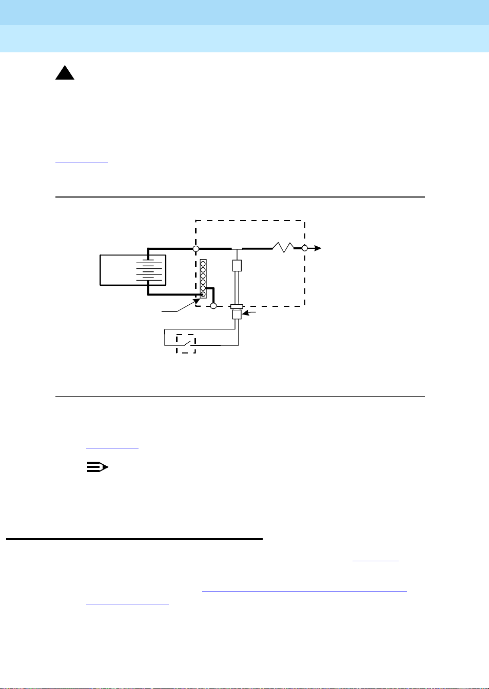
Figure 1-10
shows the cabling from the auxiliary contacts inside the EPO switch
assembly and how they connect to the internal relay.
Power Distribution Unit
Battery
Cabinet
Ground
Terminal
Bar
Auxiliary Contacts
TB3
TB1
in EPO Switch
2
Relay
(K1)
RPO Cable
6
Shunt
To Carriers
AtoE
0026_3 RBP080196
Figure 1-10. Remote Power Off Cable Connections — Part 2
1. Connect the RPO wires to the auxiliary contacts on the EPO switch. See
Figure 1-10
.
NOTE:
The EPO switch and the auxiliary contacts for the RPO connection
are customer-supplied.
Connect External Alarm Cable
1. Plug the external alarm cable into the connector shown in Figure 1-9.
2. Route the opposite end of the cable to the MDF. The alarm cable is
connected to the MDF in Chapter 5, ‘‘
Other Equipment’’.
Install and Wire Telephones and

DEFINITY ECS Release 8.2 Installation and Test
for Multi-Carrier Cabinets
Install and Connect Cabinets
1
555-233-114
Connect AC Power to Stratum 3 Clock Cabinet
The clock cabinet requires a 120 VAC, 15 Amp receptacle. The green wire
ground provided by the receptacle is sufficient. The clock cabinet does not
require a ground connection back to the single-point ground.
Check Commercial Power and Connect AC Power
Before powering up the system, check the AC power using a KS-20599 digital
voltmeter (DVM) (or equivalent).
1. Set the DVM to the 250 volt range.
2. Carefully measure the voltage between the hot and neutral side of the
receptacle. The neutral wire is white, the hot wire is black.
3. Verify the meter reads 106 to 128 VAC. If not, have a qualified electrician
correct the problem.
Issue 1
April 2000
1-26Connect AC Power to Stratum 3 Clock Cabinet
4. Measure the voltage between the neutral and ground side of the
receptacle. The ground wire is green.
5. Verify the meter reads 0 VAC. If not, have a qualified electrician correct the
problem.
6. Set all cabinet power modules OFF. Plug the AC power cable into the
receptacle.
Connect DC Power and Ground to Stratum 3 Clock Cabinet
1. Provide power for the clock cabinet from the same DC power plant as the
DEFINITY System.
2. Ground the clock cabinet to the DC power plant.
Connect Clock Cabinet Grounding
1. Measure and cut a 6 AWG (#40) (16 mm2) wire long enough to reach from
the clock cabinet to the ground discharge bar in the DC power plant.
2. Insert 1 end of the wire into the ground lug on the clock cabinet and
tighten the screw.
3. Attach the lug to the receptacle cover. Be sure the lug and cabinet ground
wires are connected to separate screws on the receptacle cover.
4. Route the ground wire to the DC power plant and connect to DISCH GRD
inside the cabinet.

DEFINITY ECS Release 8.2 Installation and Test
for Multi-Carrier Cabinets
Install and Connect Cabinets
1
555-233-114
Connect Stratum 3 Clock DC Power
1. Set the clock cabinet circuit breaker at the DC power plant OFF.
2. At the clock cabinet, connect a 6 AWG (#40) (16 mm
-48V terminal on the terminal strip.
3. At the clock cabinet, connect a 6 AWG (#40) (16 mm
-48VRTN terminal on the terminal strip.
4. Route the wires out of the cabinet and to the DC power plant.
5. At the DC power plant, connect the -48V wire to the DC OUTPUT circuit
breaker.
6. At the DC power plant, connect the -48VRTN wire to the DISCH GRD bar.
Fiber Optic Duplication Interface Cabling (R8si only)
If not already installed, interconnect the A and B port networks (TN792) with the
14-in. fiber optic cable (comcode 848204434—see Figure 1-11
Issue 1
April 2000
1-27Fiber Optic Duplication Interface Cabling (R8si only)
2
) ground wire to the
2
) wire to the
).
EMERTR
C
Lucent
S
P
E
B
O
T
AU
A
E
D
ALARMS
I
R
E
OV
EMERTR
A
B
Lucent
S
P
E
B
O
T
AU
A
E
D
ALARMS
I
R
E
OV
EMERTR
A
B
A
R
D
I
N
U
S
E
C
A
R
D
I
N
U
S
E
fodf792 KLC 090399
Figure 1-11. Fiber optic cable connecting the two duplication interface circuit
packs.

DEFINITY ECS Release 8.2 Installation and Test
for Multi-Carrier Cabinets
Install and Connect Cabinets
1
555-233-114
Fiber Optic Interconnect Cabling
Signals between the cabi nets are carried by fiber optic cables. Lightwave
transceivers provide the required fiber optic interface.
The fiber optic cables from the DEFINITY System route to a Lightguide
Interconnect Unit (LIU) or fiber optic shelf. Refer to Appendix A, ‘‘
Fiber Optic Cables’’. Refer to this information for fiber optic equipment comcode
numbers, connecting to LIUs or shelves, and routing through lightguide
equipment.
Use multi-mode fiber transceivers and mul ti-mode fiber optic cables between
cabinets unless single-mode fiber is required (distance restrictions). Use metallic
cables between carriers.
!
CAUTION:
The DEFINITY ECS may contain a Class 1 LASER device if single-mode
fiber optic cable is connected to a remote Expansion Port Network (EPN).
The LASER device operates within the following parameters:
Issue 1
April 2000
1-28Fiber Optic Interconnect Cabling
Connecting
■ Maximum Power Output: -5 dBm
■ Wavelength: 1310 nm
■ Mode Field Diameter: 8.8 µm
CLASS 1 LASER PRODUCT
IEC 825 1993
!
CAUTION:
Use of controls or adjustments or performance of procedures other than
those specified herein may result in hazardous radiation exposure.
Contact your Lucent Technologies representative for more information.
Connect Fiber Optic Cables
NOTE:
Always use the Cable Running List that accompanies the system when
installing fiber optic cables. The following procedure is a typical example of
how to cable a system.
If the cabinets are close together, the signal may go through a single, directlyconnected fiber optic cable. If the cabinets are far apart, it may be easier to
connect the cabinets through an LIU or fiber shelf.

DEFINITY ECS Release 8.2 Installation and Test
for Multi-Carrier Cabinets
Install and Connect Cabinets
1
555-233-114
For each fiber indicated in the fiber optic Cable Running List:
1. Install a lightwave transceiver on the cabinet connector at the position in
the FROM column in the running list.
2. Select a cable indicated by the CABLE CODE and LENGT H in the running
list. Connect 1 of the fibers to each connector on the lightwave
transceivers just installed. The fiber is numbered 1 or 2. The connector on
the transceiver is labeled TX or RX. Keep track of which fiber connects to
which transceiver connector. Label both ends of these cables.
3. Route the fiber optic cables from the transceiver out of the cabinet. Secure
the cables to the cable-tie rack. Keep the fiber optic cables clear of the
heavier I/O cables.
4. If the cabinet in the TO column in the running list is located remotely from
the FROM cabinet, connect to the TO cabinet by way of the LIU.
5. Install a lightwave transceiver on the cabinet connector at the position in
the TO column in the running list.
6. Route the cables from the FR OM cabinet down into the cable trays of each
EP N cabinet. Connect the cables to the lightwave transceiver just installed
on the TO cabinet.
Issue 1
April 2000
1-29Fiber Optic Interconnect Cabling
7. Connect the fiber that comes from the TX connector of the FROM
transceiver to the RX connector of the TO transceiver and vice versa.
8. Route the cables through the cabinet and through cable organizers as
provided. Secure the cables to the cable-tie rack.
CSS-Connected System with 1 Switch Node
Standard-Reliability
Figure 1-12 shows typical fiber optic cabling between cabinets. The cable
between the EI and SNI on the PPN is a pre-installed metallic cable (H600-278).
1. If no running list is available, use the outer slots first in alternating order.
Connect the first 2 SNI slots to 3 and 20 (the leftmost and rightmost of the
unused slots). Next, use 4 and 19, and so forth.
2. Add links to the EPNs in alternating order (20, 3, 19, 4, 18, 5, and so forth).

DEFINITY ECS Release 8.2 Installation and Test
for Multi-Carrier Cabinets
Install and Connect Cabinets
1
555-233-114
Issue 1
April 2000
1-30Fiber Optic Interconnect Cabling
Figure Notes
1. Cabinet 1 (PPN with 1 Switch Node)
2. Cabinet 2 through 16 (EPN)
Figure 1-12. Standard Reliability CSS-Connected Release 8r with 1 Switch
High-Reliability
Figure 1-13 shows typical fiber optic cabling between cabinets. The cable
between the EI and SNI on the PPN cabinet is a pre-installed metallic cable
(H600-278).
1. Connect the cables between the PPN cabinet and each EPN cabinet in an
3. H600-278 Metallic Cable
4. To other EPNs
Node
alternating port slot order: 3, 19; 4, 18; 5, 17; and so forth. Cabinet 1 is a
Release 8r PPN with 1 Switch Node.

DEFINITY ECS Release 8.2 Installation and Test
for Multi-Carrier Cabinets
Install and Connect Cabinets
1
555-233-114
Issue 1
April 2000
1-31Fiber Optic Interconnect Cabling
Figure Notes
1. Cabinet 1 (PPN with 1 Switch Node)
2. Cabinet 2 through 15 (EPN)
Figure 1-13. High-Reliability CSS-Connected with 1 Switch Node
Critical Reliability
Figure 1-14 shows typical fiber optic cabling between cabinets. The cable
between port slots 1 and 2 on each switch node is a metallic cable (H600-278).
1. Connect the 2 groups of 1 to 15 cables between the PP N and each EPN in
an alternating port slot order: 20, 3; 19, 4; 18, 5; and so forth.
3. H600-278 Metallic Cable
4. To other EPNs

DEFINITY ECS Release 8.2 Installation and Test
for Multi-Carrier Cabinets
Install and Connect Cabinets
1
555-233-114
Issue 1
April 2000
1-32Fiber Optic Interconnect Cabling
Figure Notes
1. Cabinet 1 (PPN with 1 Duplex Switch
Node)
3. H600-278 Metallic Cable
4. To other EPNs
2. Cabinet 2 through 16 (EPN)
Figure 1-14. Critical-Reliability CSS-Connected with 1 Switch Node
2. Both connections from each EPN must go to the same slot number. For
example: EPN cabinet 2, 2A1 to 1E3 and cabinet 2, 2B2 to 1D3.

DEFINITY ECS Release 8.2 Installation and Test
for Multi-Carrier Cabinets
Install and Connect Cabinets
1
555-233-114
Earthquake Protection Installation
Install Concrete Floor Mounting
1. Position the cabinet in the exact position it is to occupy when the
installation is complete.
2. Insert a pencil or marker through the holes previously occupied by the
carriage bolts (front and rear) in the bottom of the cabinet and mark the
floor directly beneath each hole.
3. Roll the cabinet out of the way and drill four 1/2-in. (1.27 cm) diameter
holes about 1.5 in. (3.8 cm) deep at the locations marked in Step 2.
4. Insert concrete floor anchors (STARR part number 3425) into the holes.
5. Roll the cabinet back into place and align the cabinet holes over the
concrete floor anchors.
Issue 1
April 2000
1-33Earthquake Protection Installation
6. Adjust the leveling legs until the cabinet is level. See Figure 1-15
NOTE:
If the system is supplied with cable ductwork, the cabinets must be
level from front to rear and from side to side. They must be square
with respect to each other to within ±1/8-in. (0.3 cm).
7. Secure the cabinet to the floor with the 4 supplied 3/8-16 x 4.5-in. (11.4
cm) bolts and four 3/8-in. flat washers.
8. Repeat this procedure for each cabinet to be installed.
Install Raised Computer Floor Mounting
1. Position the cabinet in the exact position it is to occupy when the
installation is complete.
2. Insert a pencil or marker through the holes previously occupied by the
carriage bolts (front and rear) in the bottom of the cabinets and mark the
raised floor panels directly beneath each hole.
3. Roll the cabinet out of the way and drill 4 holes 5/8-in. (1.6 cm) in diameter
through the raised floor panels marked in Step 2.
!
CAUTION:
Take care while drilling the holes through the raised floor that the drill
bit does not penetrate any cables below the floor that could cause
damage to the cable or injury to the installer.
.
4. Insert a long punch through the holes drilled in Step 3 and mark the
concrete floor beneath the raised floor panels.

DEFINITY ECS Release 8.2 Installation and Test
for Multi-Carrier Cabinets
Install and Connect Cabinets
1
555-233-114
5. Remove the raised floor panels in which the holes were drilled.
6. Using 1/2-in. (1.3 cm) anchor bits, drill a hole at each of the locations
marked in Step 4. Stop drilling when the mark on the side of the bit
reaches the floor level.
7. Insert a concrete floor anchor (STAR R part number 3425) into the hole until
the mark on the bit reaches floor level again. Snap the top of the anchor bit
off. Repeat for the remaining holes.
Issue 1
April 2000
1-34Earthquake Protection Installation
3/8 inch
flat washer
4inches
(10.16 cm)
3/8 - 16
threaded rod
raised
floor
variable
height
concrete
subfloor
3/8 - 16
Concrete floor
anchor
cab_base CJL 052096
Figure 1-15. Earthquake Mounting — Raised Computer Floor
Nut welded
to frame
Leveling
foot

DEFINITY ECS Release 8.2 Installation and Test
for Multi-Carrier Cabinets
Install and Connect Cabinets
1
555-233-114
8. A 3/8-16 threaded rod (part number 845557073) is used to secure the
cabinet to each concrete floor anchor. See F igure 1-15
Measure the distance from 1 of the anchors to the bottom of the cabinet.
Add 1/2-in. (1.3 cm) to this measurement to allow the rod to be threaded
into the floor anchor. Add an additional 1/2-in. (1.3 cm) to allow the rod to
protrude up through the bottom of the cabinet. For example: if the
distance from the floor anchor to the bottom of the cabinet is 10 in. (25
cm), cut the threaded rod 11 in. (27.9 cm) long.
9. When all 4 threaded rods are cut, replace the raised floor panels removed
in Step 5.
10. Position the cabinet over the holes and adjust the leveling legs until the
cabinet is level.
NOTE:
If the system is supplied with cable ductwork, the cabinets must be
level from front to rear and from side to side. They must be square
with respect to each other to within +-1/8-in. (0.3 cm).
Issue 1
April 2000
1-35Earthquake Protection Installation
.
11. Insert the threaded rods through the cabinet bottom and thread into the
concrete floor anchors.
12. Place a 3/8-in. flat washer onto each rod. Thread a 3/8-16 hex nut onto
each rod and tighten securely.
13. Repeat this procedure for each cabinet to be installed (including the
Auxiliary Cabinet and the Stratum 3 Clock Cabinet).

DEFINITY ECS Release 8.2 Installation and Test
for Multi-Carrier Cabinets
Install and Connect Cabinets
1
555-233-114
Issue 1
April 2000
1-36Earthquake Protection Installation

DEFINITY ECS Release 8.2 Installation and Test
for Multi-Carrier Cabinets
Install Telecommunications Cabling
2
555-233-114
Install Telecommunications Cabling
Equipment Room Hardware
Issue 1
April 2000
2-1Equipment Room Hardware
2
SYSTIMAX 110-type hardware is used for the Main Distribution Frame (MDF).
110-type hardware is available in 2 basic types: the 110A and 110P. The 110A
requires less wall space than the 110P. The 110P includes horizontal and vertical
cable troughs for managing cross-connect cables. The system connects to the
MDF with the supplied B25A 25-pair cables.
Refer to DEFINITY Communications System Generic 1 and Generic 3 Main
Distribution Field Design, 555-230-630, for more information.
Figure 2-1
figure when cross-connecting wire pairs to the MDF.
shows the cross-connections for common circuit packs. Refer to the

DEFINITY ECS Release 8.2 Installation and Test
for Multi-Carrier Cabinets
Install Telecommunications Cabling
2
555-233-114
Issue 1
April 2000
2-2Equipment Room Hardware
24
233
22211
20
17
16 258
14
13
12 21
71625817
514233122161524918
110194132221120
w/ E&M Signaling
Port Tie Trunk
Port MET Line
4
4
4 Port Tie Trunk
Port Analog
8
Port CO
8
10 19
918
7
615
5
4
1
Port Data Line8
Port Digital8
Port DID8
Port Hybrid8
Port BRI12
Port Analog
16
16
Port Digital
Port Analog
24
Port Digital
24
DS1
widfccf2 EWS 102798
Figure 2-1. Example MDF Connections

DEFINITY ECS Release 8.2 Installation and Test
for Multi-Carrier Cabinets
Install Telecommunications Cabling
2
555-233-114
Cross-Connect Fields
Each MDF contains a trunk/auxiliary field and a distribution field. The
trunk/auxiliary field contains 3 cross-connect areas:
1. The green field terminates the network interface leads from the Central
Office (CO) and provides the terminals to cross-connect the leads to the
purple or yellow fields as required. A single row of the 110-type terminal
block can terminate twenty-four 1-pair, eight 3-pair, or twelve 2-pair
trunks.
2. The purple field terminates the trunk circuits from the system with
WP-90929, List 1 or 3 concentrator cables. Also, 25-pair cables can be
used to terminate trunk circuits from the system with each trunk circuit
pack connecting to one 25-pair row of the 110-type terminal block. Each
terminal block row can terminate twenty-four 1-pair, eight 3-pair, or twelve
2-pair trunks.
3. The yellow field provides cross-connect terminals for all miscellaneous
leads from the system, such as alarm monitors, emergency transfer relay
power, and attendant console power. This field is used for emergency
transfer wiring, paging equipment, music sources, and so forth.
Issue 1
April 2000
2-3Equipment Room Hardware
The distribution field contains 4 cross-connect areas:
1. The purple field (port field) terminates 25-pair cables from the system.
Each line circuit pack connects to one 25-pair row of the 110-type terminal
block. One 25-pair cable is required for each line circuit pack.
NOTE:
This is the case except for the 16 port analog circuit pack and the
MET circuit pack. The 16-port analog line circuit pack requires an
adapter cable to connect from 1 connector on the system to 2
25-pair connectors on a 110-type terminal block. Two MET circuit
packs require a concentrator cable to connect from 2 connectors on
the system to one 25-pair connector on a 110-type terminal block.
2. The yellow field (auxiliary field) terminates all 25-pair cables from the
auxiliary cabinet and adjunct equipment cabinets. The yellow field is
located in the lower right-hand corner of the distribution field.
3. The white field (station field) terminates the station wiring. The white field
indicates 3-pair station circuits (8 circuits per 25-pair cable) routed
through a satellite closet.
4. The blue field (station field) also terminates station wiring. The blue field
indicates 3- and/or 4-pair station circuits (8 or 6 circuits, respectively, per
25-pair cable). The fourth pair, of the 4-pair station circuit provides adjunct
power from the cross-connect field on an as-needed basis to terminals
within 250 ft (76 m) (wire length) of the MDF.

DEFINITY ECS Release 8.2 Installation and Test
for Multi-Carrier Cabinets
Install Telecommunications Cabling
2
555-233-114
Main Distribution Frame
The MDF is located directly behind the system cabinet. Figure 2-2 shows a
typical installation using 900-pair 110P-type terminal blocks.
Issue 1
April 2000
2-4Main Distribution Frame
Figure Notes
1. Multicarrier Cabinet
2. Z113A Cable Slack Manager
3. 25-Pair Cable to System Cabinet
4. Station Cables
Figure 2-2. Typical 110A-Type Terminal Blocks
mccmdf KLC 060596
5. Station Distribution Field
6. Port Distribution Field
7. Trunk/Auxiliary Field

DEFINITY ECS Release 8.2 Installation and Test
for Multi-Carrier Cabinets
Install Telecommunications Cabling
2
555-233-114
Installation Requirements
Sneak Fuse Panels and Emergency Transfer Units
Approximately 8 in. (20 cm) of horizontal wall space is required for each column
of sneak fuse panels. Up to 25 connector pairs can be protected by each panel.
Horizontal wall space must also be provided for emergency transfer units.
110-Type Hardware
The trunk/auxiliary field and the distribution field are mounted on the same wall.
Each 110P-type terminal block is 8.5 in. (21.6 cm) wide. Vertical patch cord
troughs are 5.31 in. (13.4 cm) wide and horizontal patch cord troughs are 23 in.
(58.4 cm) wide.
Each 110A-type terminal block is 10.81 in. (27.4 cm) wide; however, no
horizontal patch cord troughs are used and the blocks are shorter than
110P-type terminal blocks. This allows the 110A-type terminal blocks to be
stacked. Therefore, the 110A-type hardware requires less space than the
110P-type hardware on a per-station basis.
Issue 1
April 2000
2-5Installation Requirements
Cable Slack Manager
A Cable Slack Manager is 32 in. (81.3 cm) wide. The quantity of which is
determined by dividing the total length of the MDF in in. (cm) by 32 (81.3). A
partial number of 0.4 or less should be rounded down, and a partial number of
0.5 or more should be rounded up (for example: 2.4 = 2 cable slack managers
and 2.5 = 3 cable slack managers).
NOTE:
Cable clamps are required in installations with cable slack managers. At
the rear of the cabinets, on each rear ground plate, install 2 cable clamps
using the screws provided. These clamps hold the 25-pair input/output or
MDF cables in place.

DEFINITY ECS Release 8.2 Installation and Test
for Multi-Carrier Cabinets
Install Telecommunications Cabling
2
555-233-114
Install Equipment and Cables
Hardware Installation
The following procedures assume 1 system technician is performing the
installation. Procedures are provided for installing the following:
■ Main Distribution Frame (MDF)
■ Cable Slack Managers
■ Sneak Fuse Panels
■ Labels for the Main Distribution Frame
Install the Main Distribution Frame
The preferred MDF location is directly behind the system cabinets.
Wall Mounting 110A-Type Terminal Blocks
Issue 1
April 2000
2-6Install Equipment and Cables
The 110A-type hardware can be stacked in almost any arrangement at any
height or location on the wall. One arrangement is shown in Figure 2-3
. The
distance between the mounting screw holes on the terminal blocks is 10.81 in.
(27.4 cm). If a vertical patch cord trough is used, the distance between the
mounting screw holes is 5.31 in. (13.3 cm).

DEFINITY ECS Release 8.2 Installation and Test
for Multi-Carrier Cabinets
Install Telecommunications Cabling
2
555-233-114
Issue 1
April 2000
2-7Install Equipment and Cables
Figure Notes
1. 4 ft (1.22 m)
2. 6.6 ft (2 m)
3. 7.68 in. (19.5 cm)
4. 7/8-in. (2.22 cm)
6. 47.5 in. (120.6 cm)
7. Horizontal Line
8. AC Power Strip
9. Floor Line
5. 5.31 in. (13.5 cm)
Figure 2-3. 110A-Type Terminal Blocks (300-Pair)
r758420b MMR 031496

DEFINITY ECS Release 8.2 Installation and Test
96
for Multi-Carrier Cabinets
Install Telecommunications Cabling
2
555-233-114
Wall Mounting 110P-Type Terminal Blocks
The first terminal block of the trunk/auxiliary field is aligned with the left side of
the system c abinet. See Figure 2-4
right side of the MDF.
Issue 1
April 2000
2-8Install Equipment and Cables
. This arrangement allows for growth on the
Figure Notes
1. 4 ft (1.22 m)
2. Horizontal Line
3. 7.68 in. (19.5 cm)
4. 47.5 in. (120.6 cm)
5. 5.31 in. (13.5 cm)
6. 7/8-in. (2.22 cm)
7. 23 in. (58.4 cm)
8. 8 ft (2.43 m)
9. AC Power Strip
10. Floor Line
Figure 2-4. 110P-Type Terminal Blocks (900-Pair)
r758421bMMR0314

DEFINITY ECS Release 8.2 Installation and Test
for Multi-Carrier Cabinets
Install Telecommunications Cabling
2
555-233-114
1. If you are installing 300-pair terminal blocks, draw a level horizontal line on
the wall 47.5 in. (1.2 m) above the floor. See Figure 2-3
If you are installing 900-pair terminal blocks, draw a level horizontal line on
the wall 23 in. (58.4 cm) above the floor. See Figure 2-4
2. To mount the first trunk/auxiliary field terminal block, partially install 2
3/4-in. #12 wood screws, 7-11/16 in. (19.5 cm) apart on the left side of the
horizontal line on the wall.
3. Slide the bottom terminal block ft onto the mounting screws and mark the
upper mounting screw locat ions.
4. Remove the terminal block and partially install the upper mounting
screws.
5. Place the terminal block on the mounting screws and tighten the screws.
6. If installing a vertical patch cord trough, partially install the first screw for
the patch cord trough, on the line, 7/8-in. (2.2 cm) to the right of the
previous screw. Partially install the second mounting screw 5.31 in. (13.5
cm) to the right of the screw just installed. Repeat Steps 3, 4, and 5.
Issue 1
April 2000
2-9Install Equipment and Cables
.
.
7. If another trunk/auxiliary field terminal block is to be installed, partially
install the first screw for the terminal block, on the line, 7/8-in. (2.2 cm) to
the right of the previous screw. Partially install the second mounting screw
7-11/16 in. (19.5 cm) to the right of the screw just installed. Repeat Steps
3, 4, and 5.
8. If a horizontal patch cord trough is to be installed, install it, on the line,
between the trunk/auxiliary field and the distribution field.
9. To install the first distribution field terminal block, partially install 2 3/4-in.,
#12 wood screws, 7-11/16 in. (19.5 cm) apart on the line, to the right of the
vertical patch cord trough. Repeat Steps 3, 4, and 5.
10. If installing another distribution field terminal block, partially install the first
screw for the terminal block, on the line, 7/8-in. (2.2 cm) to the right of the
previous screw. Partially install the second mounting screw 7-11/16 in.
(19.5 cm) to right of the screw just installed. Repeat Steps 3, 4, and 5.
11. If installing a vertical patch cord trough in the distribution field, repeat Step
6.
12. Repeat Steps 10 and 11 until all the terminal blocks and vertical patch
cord troughs in the distribution field are installed.

DEFINITY ECS Release 8.2 Installation and Test
for Multi-Carrier Cabinets
Install Telecommunications Cabling
2
555-233-114
Frame Mounting 110P-Type Terminal Blocks
The 900-pair 110P-type terminal blocks and the associated patch cord troughs
can also be mounted on a free-standing, floor-mounted 1110A2 Apparatus
Mounting Frame. See Figure 2-5
.
Issue 1
April 2000
2-10Install Equipment and Cables
r781401 LJK 040896
Figure Notes:
1. 1110C1 Apparatus Mounting
2. 1110A2 Apparatus Mounting
4. 88.5 in. (225 cm)
5. 43.5 in. (110.5 cm)
3. 76 in. (193 cm)
Figure 2-5. 1110A2 and 1110C1 Apparatus Mountings

DEFINITY ECS Release 8.2 Installation and Test
for Multi-Carrier Cabinets
Install Telecommunications Cabling
2
555-233-114
Each 1110A2 provides the space to mount 5 terminal blocks/patch cord troughs
on each side of the frame. A cable support structure, apparatus mounting
1110C1, mounts directly on top of the 1110A2 and provides support for all
cables routed to and from the frame.
Apparatus Mounting Frame Ordering Information
Code Number Description Comcode
1110A2 Apparatus Mounting Frame 104032495
1110C1 Cable Support Assembly 104175120
1110A1 End Dress Panel 104176268
2110A1 Top Dress Panel 104176276
2110B1 Bottom Dress Panel 104176284
Install Cable Slack Managers
Issue 1
April 2000
2-11Install Cable Slack Managers
1. Place the Z113A Cable Slack Manager against the wall under the MDF.
See Figure 2-6
. Align the left side of the cable slack manager with the first
terminal block of the trunk/auxiliary field.
2. Place the next cable slack manager beside the previously installed unit.
Align the tabs and interlocks and snap the units together.
3. Repeat Step 2 until all cable slack managers are installed.
NOTE:
Nine 1/4-in. holes (0.63 cm) are provided in a cable slack manager
base if earthquake mounting is required. If a base is mounted on an
uneven floor, shims may be required for leveling and to assure
proper fit of the covers.
Holes are provided in the sides of the base for bolting cable slack
manager together. Bolts and shims must be obtained locally.
4. The system cables will route through the cable slack manager as shown.
Complete cable routing is covered later in this chapter.

DEFINITY ECS Release 8.2 Installation and Test
6
for Multi-Carrier Cabinets
Install Telecommunications Cabling
2
555-233-114
Figure Notes:
Issue 1
April 2000
2-12Off-Premises Circuit Protection
cbdfflr CJL 10239
1. System Cabinet
2. Cable Slack Manager
3. Cable Clamp
4. Spare Center Troughs
5. Cabinet Trough for Port Cables
Figure 2-6. Cable Routing Through Cable Slack Manager
Cable clamps are required in installations with cable slack managers. At the rear
of the cabinets, install 2 cable clamps using the screws provided. These clamps
hold the 25-pair input/output or MDF cables in place. Figure 2-6
clamp placement and cable routing.
Off-Premises Circuit Protection
Pr otection from hazardous voltages and currents is required for all off-premises
(out of building) trunks, lines, and terminal installations. Both over-voltage
protection (lightning, power induction, and so forth), and sneak current
protection are required. Sneak current protectors must be either UL listed/CSA
certified, or must comply with local safety standards.
Sneak current protectors must have a maximum rating of 350 mA, and a
minimum voltage rating of 600V, or as required by local regulations. The following
devices protect the system from over-voltages:
shows cable
■ Analog trunks use the 507B sneak protector or equivalent. Over-voltage
protection is normally provided by the local telephone company.

DEFINITY ECS Release 8.2 Installation and Test
for Multi-Carrier Cabinets
Install Telecommunications Cabling
2
■ Analog voice terminals use one of the following types of combined
555-233-114
over-voltage and sneak current protection, or equivalent:
— Carbon block with heat coil for UL code 4B1C
— Gas tube with heat coil for UL code 4B1E-W
— Solid state with heat coil for UL code 4C1S
■ DCP and ISDN-BRI terminals use the solid state 4C3S-75 with heat coil
protector, or equivalent
■ DS1/E1/T1 circuits require isolation from exposed facilities. This isolation
may be provided by a CSU (T1), LIU (E1), or other equipment that
provides equivalent protection
Install Sneak Fuse Panels
Sneak current protection is required between the incoming RJ21X or RJ2GX
network interface and the system for both trunk and off-premise circuit packs.
Issue 1
April 2000
2-13Install Sneak Fuse Panels
The Model 507B sneak current fuse panel, or equivalent, is recommended for
sneak current protection. See Figure 2-7
. The panel contains two 25-pair
connectors, fuse removal tool, and fifty 220029 Sneak Fuses (and 2 spares).
B25A connector cables connect the network interface to the sneak fuse panel.
Also, 157B connecting blocks equipped with SCP-110 protectors can be used
for sneak current protection.
Table 2-1. Sneak Fuse Panel Ordering Information
Description Comcode
157B Connecting Block 403613003
SCP-1 10 Protec to r 406948976
507B Sneak Current Fuse Panel 107435091
220029 Sneak Current Fuse 407216316
NOTE:
Sneak current protectors with a rating of 350 mA at 600 Volts must be UL
listed for domestic installation and CSA certified for Canadian installation.
The 507B includes 52 sneak fuses and 2 cables and can be ordered using
PEC code 63210.
The SCP-110 protectors are used with 110-type hardware and on the 507B
Sneak Fuse Panel. The S CP-110 Protectors can be ordered separately and
installed on the 157B connecting block. Fifty protectors are required per
block.

DEFINITY ECS Release 8.2 Installation and Test
for Multi-Carrier Cabinets
Install Telecommunications Cabling
2
555-233-114
Issue 1
April 2000
2-14Install Sneak Fuse Panels
Sneak
Current
Protector
507B
sneak CJL 032096
Figure Notes:
1. Sn eak Fuse Panel
2. 25-Pair Male Connector (In)
3. 25-Pair Female Connector (Out)
4. 220029 Fuses (Inside Panel). Use
Small Screwdriver to Pry Top Cover Off
Figure 2-7. Model 507B Sneak Fuse Panel
1. Locate the 507B near the network interface or the MDF.
2. Hold the panel against the mounting surface and mark the mounting
screw locations. Drill pilot holes at the marked locations and partially
install a locally obtained #12 x 3/4-in. screw into the 2 bottom mounting
slots.
3. Slide the sneak fuse panel onto the mounting screws and tighten the
screws securely.
4. Install a locally obtained #12 x 3/4-in. screw into the top 2 mounting slots
and tighten securely.
5. Repeat the procedure for each sneak fuse panel.

DEFINITY ECS Release 8.2 Installation and Test
for Multi-Carrier Cabinets
Install Telecommunications Cabling
2
555-233-114
Table 2-2 is a pinout of the cable wiring and associated fuse numbers.
Table 2-2. Sneak Fuse Connector Pinout
Connector
Pin
Numbers
Pair/Fuse
Number
26/1 1
27/2 2
28/3 3
29/4 4
30/5 5
31/6 6
32/7 7
33/8 8
34/9 9
35/10 10
36/11 11
37/12 12
38/13 13
39/14 14
40/15 15
41/16 16
42/17 17
43/18 18
44/19 19
45/20 20
46/21 21
47/22 22
48/23 23
49/34 24
50/25 25
Issue 1
April 2000
2-15Install Sneak Fuse Panels
6. Secure the top of each B25A cable with the captive screw on the
connector.
7. Secure the bottom of each cable with a supplied cable tie wrap.

DEFINITY ECS Release 8.2 Installation and Test
for Multi-Carrier Cabinets
Install Telecommunications Cabling
2
555-233-114
Cable Installation
Labels
The purple port label shown in Figure 2-8 is installed on both ends of the 25-pair
cables connecting to the trunk/auxiliary field and/or distribution field.
The top blue/yellow building and floor labels are for cables connecting from the
equipment room to a site/satellite location on another floor or in another building.
The yellow label is for auxiliary circuits connecting to the trunk/auxiliary field. The
bottom blue/yellow label is for 25-pair cables connecting to site/satellite closets.
Issue 1
April 2000
2-16Cable Installation
1A2
A
labels LJK 060396
Figure Notes:
1. Purple Label (Port Cable)
2. Blue/Yellow Label (Building and
3. Yellow Label (Auxiliary)
4. Blue/Yellow Label (Site or Satellite)
Floor)
Figure 2-8. Equipment Room Cabling Labels

DEFINITY ECS Release 8.2 Installation and Test
for Multi-Carrier Cabinets
Install Telecommunications Cabling
2
555-233-114
Table 2-3 details the label name and range of each label.
Table 2-3. Equipment Room Labels
Label Name Range
Port Cable 1A1-1A20, 1B1-1B20, 1C1-1C20,
1D1-1D20, 1E1-1E20
Building Field Identified
Floor Field Identified
Auxiliary Cable Field Identified
Site or Satellite A-F and/or Field Identified
Cable/Connector/Building Label Ordering Information
Description Quantity Comcode
Issue 1
April 2000
2-17Cable Installation
201A Labels 34 Sheets 103969994
Figure 2-9 shows the proper way to install a label on a 25-pair cable connector.
Install the label near the rear of the connector so it is not obscured by the cabinet
connector retainers. It can also be installed on the skin of the cable near the
connector.
Figure 2-9. Self-Stick Label on 25-Pair Cable Connector

DEFINITY ECS Release 8.2 Installation and Test
for Multi-Carrier Cabinets
Install Telecommunications Cabling
2
555-233-114
Cable Routing Guidelines
General
The following guidelines should be used when installing the equipment room
cabling. Following these guidelines will maximize use of the cable slack
managers and make future cabling additions and changes easier.
Issue 1
April 2000
2-18Cable Installation
Figure 2-10
and Figure 2-11 show typical cable routing from the cabinet to the
top and bottom of the MDF, respectively.
Figure Notes:
1. Main Distribution Frame
r758424b MMR 052996
6. Cable Slack Manager Number 2
2. AC Power Cord (AC-Power ed
Cabinets Only)
3. Cable Slack Manager Number 1
4. Trunk/Auxiliary Field
5. Station Distribut ion Field
7. Cable Slack Manager Number 3
8. System Cabinet(s)
9. To Build i ng Cables
10. 10 AWG (#25) (6 mm
Coupled Bonding Conductor
Figure 2-10. Cable Routing to Top Terminal Blocks
2
) Wire to

DEFINITY ECS Release 8.2 Installation and Test
for Multi-Carrier Cabinets
Install Telecommunications Cabling
2
555-233-114
Issue 1
April 2000
2-19Cable Installation
Figure Notes:
1. Main Distribution Frame
2. AC Power Cord (AC-Power ed
Cabinets Only)
3. Cable Slack Manager Number 1
4. Trunk/Auxiliary Field
5. Station Distribut ion Field
Figure 2-11. Cable Routing to Bottom Terminal Blocks
Route Cables to Main Distribution Frame
The following guidelines should be followed when routing cables from the
cabinet to the MDF.
■ Each port cable is connected at the cabinet and then routed along the
front trough of the cable slack manager to the connecting/terminal block
where the cable is to be terminated.
r758432b MMR 052996
6. Cable Slack Manager Number 2
7. Cable Slack Manager Number 3
8. System Cabinet(s)
9. Building Cables (Through Cable
Trough)
10. 10 AWG (#25) (6 mm
2
) Wire to
Coupled Bonding Conductor
■ Enough slack must be left at the cabinet end of the cable to allow for
proper dressing of the cables.

DEFINITY ECS Release 8.2 Installation and Test
for Multi-Carrier Cabinets
Install Telecommunications Cabling
2
■ Route the cable from the cabinet to the wall. Place the cable beside 1 of
555-233-114
the row s of columns in the cable slack manager.
NOTE:
Retainers mounted on the columns keep the cable from protruding
above the top of the base of the cable slack manager.
■ Determine the length of the cable required to reach from the cable slack
manager to the assigned connecting/terminal block.
■ The cable must be supported on the wall using “D” rings.
■ Cable slack is stored by coiling the cable around the columns in the cable
slack manager. The first run should always go across the full length of the
5 columns in the cable slack manager.
■ Connect the cable to the assigned connecting/terminal block.
■ Avoid placing copper cables where they may bend or strain fiber optic
cables.
Issue 1
April 2000
2-20Cable Installation
Install Control Carrier Outputs Cable
A connector on the rear of the Control Carrier is labeled
con nects the
the trunk/auxiliary field. The
■ Alarm monitoring for the processor interface
■ 7 DC power (-48 VDC) sources for emergency transfer units
■ 3 DC power (-48 VDC) sources for remotely powering a total of 3 attendant
AUX
connector to a 110-type terminal block in the yellow field of
AUX
consoles or executive voice terminal adjuncts
■ The remote maintenance internal modem connection location
■ Access to a relay contact is available to actuate a light, bell, or similar type
customer-supplied device. The r elay can be administered to make contact
when a major, minor, or warning alarm condition occurs in the system
Label Control Carrier Cable
Place the appropriate
block row. On the control carrier cable, place a yellow auxiliary label on the
connectors at each end of the cable. Write “AUX” on each label.
AUX
connector label on the assigned 110-type terminal
AUX
. A 25-pair cable
connector outputs include the following:

DEFINITY ECS Release 8.2 Installation and Test
for Multi-Carrier Cabinets
Install Telecommunications Cabling
2
555-233-114
Connect Control Carrier Outputs Cable
Issue 1
April 2000
2-21Cable Installation
Plug the connector cable in the
AUX
connector on the rear of the Control Carrier.
Route the connector cable through the cable slack manager to the assigned
110-type terminal block in the yellow field of the trunk/auxiliary field.
Install Trunk Cables Among Network Interface, Sneak Fuse Panel, and Cabinet
The 1-pair of Central Office (CO) trunks are installed by the network provider in
the green field. Up to 24 pairs may be terminated on each row of the 110-type
terminal block. Tie trunks also appear in the green field with up to eight 3-pair
trunks terminated on each row of the 110-type terminal block.
Select Concentrator Cables
WP-90929, List 1 and 3 concentrator cables can be used to connect the cabinet
to the 110-type terminal blocks in the purple field. The 1-pair patch cords/jumper
wires are then run from the purple terminal block rows to the green terminal block
rows in order to establish the correct 3-pair modularity.
Connect Trunk Pairs Using Concentrator Cables
Figure 2-12 shows trunk pairs connected to the cabinet with concentrator cables.
To install the cables:
1. Connect B25A cables between the network interface and sneak fuse
panels.
2. Connect A25D cables from the sneak fuse panels to the 110-type terminal
block connectors in the green field.
3. Connect patch cords/jumper wires from the terminal block in the green
field to the associated terminal block in the purple field.
4. Connect the single-fingered end of the concentrator cables to the
110-type terminal block connectors in the purple field in Step 3.
5. Connect the other end (2/3-fingered end) of the concentrator cables to the
appropriate carrier slots. Equipped carrier slots are identified on the CSD.
Mark the nomenclature strips above the carriers to identify the slots.
6. Label connectors on each end of the cables that connect to the cabinet.
7. Route the cables down the sides of the cabinet and store the excess
cable slack in the cable slack manager as previously described.

DEFINITY ECS Release 8.2 Installation and Test
for Multi-Carrier Cabinets
Install Telecommunications Cabling
2
555-233-114
Issue 1
April 2000
2-22Cable Installation
Figure Notes:
1. Trunk/Auxiliary Field
2. To Control Carrier AUX Connector
3. Concentrator Cable (WP90929, List 1)
4. Concentrator Cable (WP90929, List 3)
5. A25D (Male-to-Male) Cable
7. RJ21X/RJ2GX Network Interface
8. Sneak Fuse Panel
9. B25A Cable
10. Central Office Trunks
11. System Cabinet
6. Alternate Block/Rows
Figure 2-12. Connect Trunk Pairs Using Concentrator Cables
NEW796 THC 031296

DEFINITY ECS Release 8.2 Installation and Test
96
for Multi-Carrier Cabinets
Install Telecommunications Cabling
2
555-233-114
Connect Trunk Pairs to Cabinet Using Jumper Wires To Establish 3-Pair Modularity
Figure 2-13 on page 2-23 and Figure 2-14 on page 2-24 show trunk pairs
connected to the cabinet with jumper wires to establish 3-pair modularity.
Issue 1
April 2000
2-23Cable Installation
12345678
1 4 7 10 13 16 19 22
9 10111213141516 1718192021222324
1 4 7 10 13 16 19 22
1 4 7 1013161922
r758425bMMR0314
Figure Notes:
1. Green Field
2. 1-Pair Jumpers
3. Pairs
4. Purple Field
Figure 2-13. 3-Pair Modularity for Trunk Pairs for 1-Pair Trunks
To connect the trunk pairs to the purple field:
1. Connect B25A cables between the network interface and the sneak fuse
panels. See Figure 2-13
.
2. Connect A25D/B25A cables from the sneak fuse panels to the 110-type
terminal block-type connecting block connectors in the green field.
3. Connect 1-pair patch cords/jumper wires from each 110-type terminal
block row in the green field to the 110-type terminal block rows in the
purple field for 1-pair Central Office (CO) trunks or in Figure 2-14 on page
2-24 for 3-pair tie trunks.

DEFINITY ECS Release 8.2 Installation and Test
for Multi-Carrier Cabinets
Install Telecommunications Cabling
2
555-233-114
Issue 1
April 2000
2-24Cable Installation
3
123456789101112
123456789101112
123456789101112
1716151413 18 19 20 21 22 23 24
r758537b MMR 031496
Figure Notes:
1. Green Field
2. 1-Pair Jumpers
3. Pairs
4. Purple Field
Figure 2-14. 3-Pair Modularity for Trunk Pairs for 3-Pair Tie Trunks
Install Cables Between Cabinet and MDF
1. Install “D” rings on the wall between the cable slack manager and the
terminal/connecting blocks mounted on the MDF.
2. Install a self-adhesive port label on the back of each connector on the
connector cable. Labels should be positioned so they are not covered by
the cabinet connector retainers.
3. At the rear of the cabinet, connect 1 end of the connector cable to the
assigned connector.
4. Route the cable down the rear of the cabinet, through the cable slack
manager, and to the MDF.
5. At the MDF, connect the other end of the cable to the assigned terminal/
connecting block connector.
6. Store the cable slack in the cable slack manager.
7. Repeat Steps 2 through 6 until all cables are installed.

DEFINITY ECS Release 8.2 Installation and Test
for Multi-Carrier Cabinets
Install Telecommunications Cabling
2
555-233-114
Install Connector Cables Between Auxiliary Cabinet and MDF
Auxiliary equipment that connects to the MDF can be mounted inside the
Auxiliary cabinet. The equipment connects to an ED-1E1443-10 (Group 1)
intraconnection panel mounted in the cabinet. This intraconnection panel
consists of a 110-type 100-pair wiring block. Auxiliary equipment is connected to
the 110-type wiring block. The wiring block is pre-wired to four 25-pair female
connectors mounted on the outside rear of the cabinet.
1. Install “D” rings on the wall between the cable slack manager and the
terminal/connecting blocks mounted on the MDF.
2. Install a self-sticking port label on the rear of each connector on the B25A
connector cable. See Figure 2-9 on page 2-17
NOTE:
Labels should be positioned so they will not be obscured by the
cabinet connector retainers.
Issue 1
April 2000
2-25Cable Installation
.
3. At the rear of the Auxiliary cabinet, connect 1 end of the connector cable
to the assigned connector.
4. Route the cable down the rear of the cabinet and through the cable slack
manager to the MDF.
5. At the MDF, connect the other end of the cable to the assigned
terminal/connecting block connector.
6. Stor e the excess cable in the cable slack manager.
7. Repeat Steps 2 through 6 until all cables are installed.

DEFINITY ECS Release 8.2 Installation and Test
for Multi-Carrier Cabinets
Install Telecommunications Cabling
2
555-233-114
Install Coupled Bonding Conductor
The Coupled Bonding Conductor (CBC) connects to the single-point ground
block and runs adjacent to pairs in an associated telecommunications cable.
See Figure 2-15
reduces potential differences in terminating equipment.
. The mutual coupling between the CBC and the wire pairs
Issue 1
April 2000
2-26Install Coupled Bonding Conductor
The conductor consists of a 10 AWG (#25) (6 mm
2
) w i re t i e - wra ppe d t o t h e i n s ide
wiring cable and terminated at the CBC terminal bar at the MDF. Maintain a
minimum of 12 in. (30.5 cm) spacing between the CBC and other power and
ground leads.
The 10 AWG (#25) (6 mm
2
) wire must be long enough to reach the
telecommunications cables at the rear of the system cabinets, follow these
cables to the MDF, and to terminate at the CBC.
1. Cut a 10 AWG (#25) (6 mm
2
) wire long enough to reach from the system’s
single-point ground block or DC power cabinet ground discharge bar to
the MDF CBC block.
2. Connect 1 end of the 10 AWG (#25) (6 mm
2
) wire to the single-point
ground block (or ground discharge bar).
3. Route the wire next to the 25-pair cables connecting to the trunk/auxiliary
(purple) field.
4. Tie wrap the 10 AWG (#25) (6 mm
5. Connect the 10 AWG (#25) (6 mm
2
) wire to the 25-pair cables.
2
) wire to the MDF CBC ground block.
6. Repeat the above steps for each CBC ground wire.

DEFINITY ECS Release 8.2 Installation and Test
for Multi-Carrier Cabinets
Install Telecommunications Cabling
2
555-233-114
Issue 1
April 2000
2-27Install Coupled Bonding Conductor
Figure Notes:
1. 25-Pair Tip & Ring Cables to
Cabinets
2. Coupled Bonding Conductor (CBC)
Terminal Block
3. Ti e Wraps
4. Cable Shield or Six Spare Pairs
10. Cross-Connect Ground Block
11. Main Distribution Frame (MDF)
12. To Other Cross-Connec t Ground
5. Ground on Carbon Block Protector
or Equivalent
6. Trunk Cable to Network Interface
2
7. 10 AWG (#25) (6 mm
) Wire
13. Approved Ground
14. Coupled Bonding Conductor (CBC)
Figure 2-15. Coupled Bonding Conductor
cbc_gnd_1 PDH 062696
8. To Network Cabinets
9. Battery Plant Ground Discharge Bar
or Single-Point Ground
Blocks

DEFINITY ECS Release 8.2 Installation and Test
for Multi-Carrier Cabinets
Install Telecommunications Cabling
2
555-233-114
Station Wiring Design
The following hardware and cabling is used:
■ Information outlets (modular wall jacks)
■ Station Cables
■ Closets
— Site locations
— Satellite loc ati ons
■ Adapters
■ Labels
A brief description of each of the above listed items follows. Ordering information
is not provided for station cables and information outlets.
Information Outlets
Issue 1
April 2000
2-28Station Wiring Design
Information outlets are 8-pin modular wall jacks. Most of the outlets are wired with
push-on connections. Information outlets are also available that connect to a
double modular plug-ended 4-pair station cable routed from the MDF, a
site/satellite location, or an adapter.
Station Cables
For clarity, a station cable is either a 25-pair cable, multiple 25-pair cable, or
4-pair D-inside wire (DIW) run from the equipment room, site/satellite location, or
adapter to the information outlets. The following station cables are available. See
Figure 2-16
25-pair station cable
locations or adapters. Use an A25D cable (male to male) between the equipment
room and satellite closet. Use a B25A cable between the equipment room and
site closet or adapter.
Multiple 25-pair station cable
site/satellite locations or adapters. This cable consists of individually sheathed
25-pair cables with a factory-installed 25-pair connector on each end. Use a
male to female cable to connect between the equipment room and site location
or adapter. Use a male to male cable to connect between the equipment room
and satellite location. Staggered-finger cables are recommended for all multiple
25-pair station cables and are available in both double-ended and single-ended
types.
.
— Use between the equipment room and site/ satellite
— Use between the equipment room and

DEFINITY ECS Release 8.2 Installation and Test
for Multi-Carrier Cabinets
Install Telecommunications Cabling
2
Single modular plug-ended 4-pair station cable — Use this cable between
adapters and information outlets that require push-on connections. It can also be
used when 4-pair station cables are field- terminated on the 110-type terminal
blocks in the equipment room or satellite closet and modularly connected to
information outlets. The station cables are available in the following lengths:
555-233-114
— 10 ft (3.05 m)
— 25 ft (7.62 m)
— 50 ft (15.24 m)
— 75 ft (22.86 m)
— 100 ft (30.5 m)
— 150 ft (45.72 m)
— 200 ft (61 m)
NOTE:
If more than 200 ft (61 m) of 4-pair station cable is required, a 451A
in-line adapter (double-ended modular female connector) is
attached to the cable and a second 4-pair cable of the required
length is plugged into the adapter. See Figure 2-16
Issue 1
April 2000
2-29Station Wiring Design
.
Double modular plug-ended 4-pair station cable
nonstandard length runs between adapters and information outlets with push-on
connections. It can also be used between adapters and modularly connected
information outlets. It is available in the same lengths as the single modular
plug-ended cable.
Bulk Cable
bulk cable is not equipped with connectors. Use this cable between the
equipment room and satellite closets when both are equipped with punch-down
type terminal/connecting blocks.
4-pair station cable
field-terminated on the 110-type terminal blocks in the equipment room or
satellite closet and the information outlets require push-on connections.
451A Adapter Ordering Information
Color Comcode
Gray 103942272
Ivory 103786240
— Same as the 25-pair cable or multiple 25-pair cable; however, the
— Use this cable when 4-pair station cables are to be
— Use this cable to provide

DEFINITY ECS Release 8.2 Installation and Test
for Multi-Carrier Cabinets
Install Telecommunications Cabling
2
555-233-114
Issue 1
April 2000
2-30Station Wiring Design
Closets
1
5
4
5
3
Figure Notes:
1. Station Cable
2. Information Outlet
4. 258A Adap te r
5. 4-Pair Station Cable
3. 451A In-Line Adapter
Figure 2-16. Example of Extending 4-Pair Station Cables
2
crdfad1 CJL 101596
Site Locations
Site locations are closets that provide a point in the station wiring for the
administration of remote powering. Adapters are used at site locations to
terminate the 25-pair station cables and provide connection points (modular
jacks) for power adapters and 4-pair station cables.
The 258A and BR2580A adapters plug into a 25-pair female cable connector.
These adapters divide the 25-pair cable into six 4-pair (modular jack) circuits.
See Figure 2-17
.

DEFINITY ECS Release 8.2 Installation and Test
6
for Multi-Carrier Cabinets
Install Telecommunications Cabling
2
555-233-114
Issue 1
April 2000
2-31Station Wiring Design
1
3
4
2
4
crdfadp CJL 10159
Figure Notes:
1. BR2580A Adapter
2. 258A Adapter
3. 25-Pair Male Ribbon Connector
4. 4-Pair Modular Jacks (8 Pins)
Figure 2-17. 258A and BR2580A Adapters
The 356A adapter plugs into a 25-pair female cable connector. See Figure 2-18
The 356A adapter divides the 25-pair cable into eight 3-pair circuits. Although
the circuits are 3-pair, the adapters modular jacks will accept the 8-wide modular
plug used on the 4-pair station cable.
.
!
CAUTION:
Adapters wired similarly to the 356A should not be used. Their jacks do not
accept 4-pair plugs.

DEFINITY ECS Release 8.2 Installation and Test
for Multi-Carrier Cabinets
Install Telecommunications Cabling
2
555-233-114
1
Issue 1
April 2000
2-32Station Wiring Design
2
crdf356 CJL 101296
Figure Notes:
1. 356A Adapter 2. 4-Pair Modular Jacks (6 pins each,
connected to 25-pair ribbon connector)
Figure 2-18. 356A Adapter
Use the ZD8AJ adapter to connect a Multi-button Electronic Telephone (MET)
line cord to an information outlet. The adapter interchanges pairs 3 and 4 to
correspond with the pair assignments for the telephone. The line cord plugs into
the adapter, and then the adapter plugs into an information outlet.
Adapter Ordering Information
Description Comcode
258A Adapter 102605136
BR2580A Adapter 403384720
356A Adapter 104158829
400B Adapter 103848859
400B2 Adapter 104152558
ZD8AJ Adapter 103881421

DEFINITY ECS Release 8.2 Installation and Test
for Multi-Carrier Cabinets
Install Telecommunications Cabling
2
555-233-114
Satellite Locations
Satellite locations are closets that provide an administration point (using
cross-connect equipment) for station cables and where adjunct power may be
applied. The station cable circuits from the equipment room MDF are 3-pair. At
the satellite location, 4-pair circuits run to the information outlets. The hardware
used is 110-type terminal blocks.
Satellite Locations Using 110-Type Hardware
Each terminal block has a 3-pair (white field) and a 4-pair (blue field) located on
the same terminal block.
The 110A-type terminal block that can be used is the 110AE1-75FT. It must be
field-terminated to both the white and blue fields.
The 300-pair 110P-type terminal blocks that can be used are:
■ 110PE1-300CT/FT — 25-pair connector on the white field and
field-terminated on the blue field
■ 110PE1-300FT — Field-terminated on both the white and blue fields
Issue 1
April 2000
2-33Station Circuit Distribution from Equipment Room
The 900-pair 110P-type terminal blocks that can be used are:
■ 110PE1-900CT/FT — 25-pair connector on the white field and
field-terminated on the blue field
■ 110PE1-900FT — Field-terminated on both the white and blue fields
Station Circuit Distribution from Equipment Room
This section explains the station circuit distribution from the equipment room to
the information outlets for new wiring installations. Example connection diagrams
are provided to show the options for running and connecting the station cables.
If most of the telephones/voice terminals that require remote powering are within
250 ft (76.2 m) of the equipment room, 4-pair station circuits are run from the
equipment room to the information outlets. If this is not the case, or if the
customer requires 2-point administration, 3-pair station circuits are run from the
equipment room to satellite locations. Then, the 4-pair station circuits are run
from the satellite locations to the information outlets.
A list of voice and data terminals that can be connected to the system is
provided i n Table 2-4 on page 2-41
connected to the system is provided in Table 2-5 on page 2-44
. A list of administration terminals that can be
.

DEFINITY ECS Release 8.2 Installation and Test
for Multi-Carrier Cabinets
Install Telecommunications Cabling
2
555-233-114
4-Pair Station Circuits
Four-pair circuits can be run directly from an equipment room MDF to a 258A or
BR2580A adapter as shown in Figure 2-19
adapter to the information outlets.
1
2 3
7
6
Issue 1
April 2000
2-34Station Circuit Distribution from Equipment Room
. The 4-pair station cables connect the
4
8 8
9
12
Figure Notes:
1. Part of Main Distribution Frame (MDF)
2. 3-Pair Connecting Blocks
3. 4-Pair Connecting Blocks
4. Purple Field
5. Blue Field
6. Patch Cord or Cross-Connect Jumpers
7. To System Cabinet (Three-Pair
Modularity)
1110
12
13
r764797a CJL 031396
8. B25A Cable
9. Connectorized (Stagg e red
Finger) Multiple 25-Pair Cable
10. 258A or BR2580A Adapter
11. Information Outlet
12. 4-Pair Circuit
13. DIW Station Cable (D-Inside
Wire)
Figure 2-19. 4-Pair Circuit Distribution and Connectivity
DEFINITY ECS Release 8.2 Installation and Test
for Multi-Carrier Cabinets
Install Telecommunications Cabling
2
555-233-114
The 4-pair station cables can be run directly from the equipment room to the
information outlets if 4-pair terminal blocks are used in the distribution field. See
Figure 2-20
. The station cables must be field-terminated on the 110-type terminal
blocks.
2
Issue 1
April 2000
2-35Station Circuit Distribution from Equipment Room
1
2
4
3
r764798a CJL 030796
5
Figure Notes:
1. Station Side of MDF or Satellite
Location
2. 4-Pair Circuit
3. Blue Field
4. DIW Station Cable (D-Inside Wire)
5. Information Outlet
Figure 2-20. 4-Pair Run to Equipment Room or Satellite Location

DEFINITY ECS Release 8.2 Installation and Test
for Multi-Carrier Cabinets
Install Telecommunications Cabling
2
555-233-114
If 110-type terminal blocks are used with a modular plug-ended station cable, an
adapter can be connected directly to the 110-type terminal block connectors.
See Figure 2-21
.
Issue 1
April 2000
2-36Station Circuit Distribution from Equipment Room
1
2
7
4
3
8
5
6
Figure Notes:
1. Part of MDF
2. 3-Pair Connecting Blocks
3. 4-Pair Connecting Blocks
4. Purple Field
5. Patch Cord or Cross-Connect Jumpers
6. Blue Field
9
11
10
r758532a CJL 031196
7. To System Cabinet (3 pair
modularity)
8. A25D Cable
9. 258A or BR2580A Adapter
10. Information Outlet
11. 4-Pair Circuit (DIW station
cable (D-Inside Wire))
Figure 2-21. 4-Pair Run to Equipment Room or Satellite Location

DEFINITY ECS Release 8.2 Installation and Test
for Multi-Carrier Cabinets
Install Telecommunications Cabling
2
555-233-114
3-Pair to 4-Pair Station Circuit Distribution
Figure 2-22 shows the 3-pair circuit distribution from an equipment room MDF to
a satellite location using 110-type hardware. Four-pair circuits are distributed
from the satellite location to the information outlets.
1
2
6
3
Issue 1
April 2000
2-37Station Circuit Distribution from Equipment Room
8
3
4
9
7
8
Figure Notes:
1. Part of MDF
2. 3-Pair Connecting Blocks
3. Purple Field
4. White Field
5. Patch Cord or Cross-Connect
Jumpers
6. To System Cabinet (3 Pair Modularity)
7. A25D Cable (3-Pair Circuits)
8. B25A Cable
15
2
4
10
16
11
12
14
9. Connectorized (staggered finger)
Multiple 25-P air Cable
10. 4-Pair Connecting Blocks
11. Blue Field
12. 258A or BR2580A Adapter
13. Information Outlet
14. 4-Pair Circuit [DIW Station Cable
(D-Inside Wire)]
15. Part of Satellite Location
16. 4-Pair Circuits (B25A Cable)
13
Figure 2-22. 3-Pair to 4-Pair Satellite Location Connectivity

DEFINITY ECS Release 8.2 Installation and Test
for Multi-Carrier Cabinets
Install Telecommunications Cabling
2
555-233-114
Three-pair circuits can also be run directly from the equipment room MDF to a
356A adapter as shown in Figure 2-23
adapter to the information outlets. Four-pair station cables can be run directly
from a satellite location to the information outlets as previously described.
1
Issue 1
April 2000
2-38Station Circuit Distribution from Equipment Room
. Four-pair station cables connect the
2 2
6
5
3
4
8
7
Figure Notes:
1. Part of Main Distribution Frame (MDF)
2. 3-Pair Connecting Blocks
3. Purple Field
4. Blue Field
5. Patch Cord or Cross-Connect Jumpers
6. To System Cabinet (3-Pair Modularity)
9
10
11
12
r758533a CJL 031196
7. B25A Cable
8. 3-Pair Circuits
9. 356A Adapter
10. Information Outlet
11. 3-Pair Circuit in 4-Pair Wire
12. DIW Station Cable (D-Inside
Wire)
Figure 2-23. 3-Pair to 4-Pair Circuit Distribution and Connectivity
NOTE:
Bridged taps are not allowed on any part of the station wiring.

DEFINITY ECS Release 8.2 Installation and Test
for Multi-Carrier Cabinets
Install Telecommunications Cabling
2
555-233-114
Layout
Locate Information Outlets
The customer or marketing representative must provide floor plans showing the
information outlet locations and types (flush- or surface-mounted) required. The
floor plans must also show a complete overview of all conduit and cabling
facilities in the building.
Locate Satellites and Sites
Use the following information when determining site, satellite, or adapter
locations.
a. Keep the number of locations to a minimum.
b. To minimize the station wiring distances, centrally locate the
sites/satellites, or adapters among the information outlets.
Issue 1
April 2000
2-39Layout
c. S ite/satellite locations must be easily accessible and contain AC-powered
receptacles.
Adapter Requirements
One 258A/BR2580A adapter is required for each 25-pair station cable containing
4-pair station circuits. One 356A adapter is required for each 25-pair station
cable containing 3-pair station circuits.
Hardware Requirements
Hardware requirements are the same as for the equipment room.
Sizing 4-Pair Station Cables
Use the scale of the floor plan to determine the approximate length of the station
cables required per the standard SYSTIMAX wiring concepts.

DEFINITY ECS Release 8.2 Installation and Test
for Multi-Carrier Cabinets
Install Telecommunications Cabling
2
555-233-114
Sizing 25-Pair and Multiple 25-Pair Station Cables
Use the scale of the floor plan to determine the approximate length of each
25-pair station cable. The cables must be selected and properly sized to make
maximum use of the hardware at the equipment room or satellite location.
Use 25-pair B25A cables to connect adapters directly to the MDF or satellite
location. Staggered-finger cables, equipped with factory-installed 25-pair
connectors at both ends, should be used when multiple 25-pair cables are used
between the equipment room or satellite location and the adapters. B25A cables
are required at the equipment room or satellite location to connect the
staggered-finger cables to the 110-type terminal blocks.
Use the following information to determine the cable size (cable pairs) required
for either 3-pair or 4-pair circuits. Note the length and size on the floor plan to aid
in the ordering and installation of the station cables.
3-Pair Station Cable Circuits
Issue 1
April 2000
2-40Layout
To determine the size of station cables containing 3-pair circuits, multiply the
number of 3-pair circuits required at the satellite location by 3.5. Then, using the
minimum size cable requirement, round up the cable size requirement to the next
highest available cable bundle size. This will provide additional pairs for growth
and compensate for every twenty-fifth pair in a cable that is not used.
4-Pair Station Cable Circuits
To determine the size of station cables containing 4-pair circuits, find out how
many information outlets are served by the equipment room MDF or satellite
location MDF. Multiply the number of information outlets by 4. Then, using the
minimum size cable requirement, round up the cable size requirement to the next
highest available cable bundle size.
NOTE:
This formula may not compensate for the unused twenty-fifth pair in all
cases. If not, it must be allowed for.

DEFINITY ECS Release 8.2 Installation and Test
for Multi-Carrier Cabinets
Install Telecommunications Cabling
2
555-233-114
Voice and Data Terminals
The system can connect to all DTE terminals and have RS-232 (or EIA-232) or
DCP interfaces. Tab le 2- 4
system. Contact your Lucent Technologies representative for more information.
Table 2-4. Voice and Data Terminals
Station Type Type
Analog sets:
500, 2500, 7101A, 7103A, 7104A, 8110, DS1SA, and
DS1FD
Other Analog Ports
Spare Ports
10MET set — 10 buttons
20MET set — 20 buttons
30MET set — 30 buttons
Terminal — 510 BCT
Terminal — 515 BCT
602A1 Callmaster I
603A1 Callmaster II
603D1 Callmaster III
603E1 Callmaster III
606A1 Callmaster IV
Digital set — 6402
Digital set — 6408
Digital set — 6408D
Digital set — 6408D+
Digital set — 6416D+
Digital set — 6416D+w/XM24B expansion module
Digital set — 6424D+
Digital set — 6424D+w/XM24B expansion module
Voice/data — 6538 Data and voice
Hybrid set — 7303S
Hybrid set — 7305S
Hybrid set — 7309H
Hybrid set — 7313H
Hybrid set — 7314H
Hybrid set — 7315H
Hybrid set — 7316H
Hybrid set — 7317H
lists some of the terminals that can connect to the
1
, Wired Spare Ports, and Non-wired
Issue 1
April 2000
2-41Voice and Data Terminals
Analog voice
Analog voice
Voice
Data
Data and voice
Digital voice
Hybrid voice
Continued on next page

DEFINITY ECS Release 8.2 Installation and Test
for Multi-Carrier Cabinets
Install Telecommunications Cabling
2
555-233-114
Table 2-4. Voice and Data Terminals — Continued
Station Type Type
Digital set — 7401D/7401+
Digital set — 7403D
Digital set — 7404D
Digital set — 7404D w/display
Digital set — 7405D
Digital set — 7405D w/display
Digital set — 7405D w/cov
Digital set — 7406D
Digital set — 7406D w/display
Digital set — 7406+
Digital set — 7406+ w/display
Digital set — 7407D
Digital set — 7407+
Digital set — 7410D
Digital set — 7410+
Digital set — 7434D
Digital set — 7434D w/display
Digital set — 7434D w/call coverage module
Digital set — 7444D
Digital set — 8403B
Digital set — 8405B/B+
Digital set — 8405D/D+
Digital set — 8410B
Digital set — 8410D
Digital set — 8411B
Digital set — 8411D
Digital set — 8434 D
Digital set — 8434 with XM24B Expansion Module
Digital set — 9403B
Digital set — 9410D
Digital set — 9434D
Basic attendant console (302A, 302B)
Enhanced atten dant console (302C)
Attendant selector console (26B1)
ISDN-BRI
— 7505D
— 7506D
— 7507D
— 8503D
— 8510T w/display
— 8520T w/display
Wireless 9601A
2
Issue 1
April 2000
2-42Voice and Data Terminals
Digital voice
Digital voice
Data and voice
BRI voice
Voice
Continued on next page

DEFINITY ECS Release 8.2 Installation and Test
for Multi-Carrier Cabinets
Install Telecommunications Cabling
2
555-233-114
Table 2-4. Voice and Data Terminals — Continued
Station Type Type
ADJLK
3
ADX8D
ADX16A
ADX16D
ASAI
CP9530
DIG800
K2500
MDC9000
MDW9000
PC
4
VMI
VMIFD
VMISA
VRU
4
4
5
VRUFD
VRUSA
WCBRI
105TL
Issue 1
April 2000
2-43Voice and Data Terminals
Voice
Voice
Continued on next page
1. Includes music-on-hold, recorded announc ement, and loudspeaker paging.
2. The radio controller supports 24 simultaneous calls and 2 wireless fixed bases.
3. Needs ASAI interface and ASAI prop adjunct links turned on in “system-parameters
customer options.”
4. Turn on mode code in ”system-parameters customer options.”
5. Needs DTMF turned on in “system-parameters customer options.”
The following notes apply to the button and data module records in Tab le 2-4:
■ Any DCP phone (except 6400- and 8400-series) can add a 7400B,
requiring 1 data module record.
■ A data module can be added to a 7403D or 7405D, requiring 1 data
modu l e record.
■ A data module (ADM-T) can be added to a 7505D, 7506D, or 7507D,
requiring 1 data module record.
■ An ISDN-BRI endpoint record is required for each distinct ISDN-BRI
endpoint. Thus each voice-only, data-only, or voice-data endpoint uses 1
of these records.

DEFINITY ECS Release 8.2 Installation and Test
for Multi-Carrier Cabinets
Install Telecommunications Cabling
2
555-233-114
Administration Terminals
Table 2-5 lists the administration terminals that can be connected to the system.
Table 2-5. Administration Terminals
Administration Terminal Application
510D Remote administration
1
610D, 513, 610, 615, 715
4410, 4425, and VT220
BCT,
Issue 1
April 2000
2-44Label the Main Distribution Frame
Management Terminal: administration and
general purpose
515 Business Communication s
Remote administration, general purpose
Terminal (BCT)
615 Management Terminal Management Terminal system
administration and maintenance terminal
715 BCS, 2900/715 BCS, and 715
BCS-2 Management Terminal
1. The keyboards and terminals are interchangeable when an adapter cable is used.
Management Terminal system
administration and maintenance terminal
NOTE:
The 715 BCS (406803148 and 406803155), has a 6-pin mini-DIN keyboard
connector. The 2900/715 BCS (4073113881 and 407313899), has a 6-pin
RJ-11 keyboard jack located on the side of the terminal.
Label the Main Distribution Frame
Figure 2-24 shows the graphic symbols used on labels for the system,
cross-connections, information outlets, and cables. The labels are color-coded to
identify system wiring:
■ Green — To Central Office (CO)
■ Purple — To system ports
■ Yellow — To auxiliary equipment and miscellaneous system leads
■ Blue — To information outlets
■ White — From Main Distribution Frame to satellite locations (3-pair)
 Loading...