

Page 1

AT&T
CALLMASTER
®
Digital Voice Terminal
User's Guide
Page 2

NOTICE
While reasonable efforts were made to ensure that the information in this document
was complete and accurate at the time of printing, AT&T can assume no responsibility
for any errors. Changes or corrections to the information contained in this document
may be incorporated into future issues.
TO ORDER COPIES OF THIS DOCUMENT
Contact:
AT&T Customer Information Center
2855 North Franklin Road
P.O. Box 19901
Indianapolis, IN 46219
1-800-432-6600,
In Canada: 1-800-255-1242
Order: Document No. 555-015-716
Issue 4, February 1991
For more information about AT&T documents, see Business Communications Systems
Publications Catalog (555-000-010).
HEARING AID COMPATIBILITY
This equipment is compatible with the inductively-coupled hearing aids prescribed by
the Federal Communications Commission (FCC).
Prepared by
© 1991 AT&T
The AT&T Technical Publications Department
All Rights Reserved
Denver, CO 80234 Printed in USA
Page 3

Contents
1
1
2
2
3
3
3
3
3
4
4
4
5
6
7
7
7
7
7
Your CALLMASTER Digital Voice Termial
Recorder Interface Module
Conventions Used in This Guide
Organization of This Guide
Physical Description
Call-Processing Area
Dial Pad
Conference, Transfer, Drop, and Hold
Message Light
Display Area
Alphanumeric Display
Display Contrast-Control Wheel
Double-Light Call-Appearance and Feature Buttons
Single-Light Feature Buttons
Front Panel
Instruction for Button-Label Strips
Self-Test Button
1-2 Switch
Ringer Volume Control
Side and Back of the Terminal
8
8
8
8
9
9
10
10
11
12
12
13
14
Side Jacks for Headsets or Handsets
Screw Holes for Optional Handset Cradles
Back Jack for Optional Kneewell Adapter
Model Number
Bottom of the Terminal
Features
Conference
Drop
Hold
Mute
Transfer
References
i
Page 4
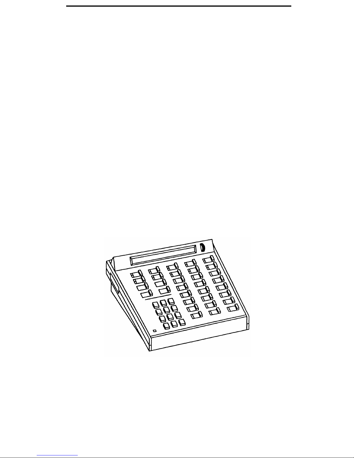
Your CALLMASTER Digital Voice Terminal
Congratulations on the addition of the AT&T CALLMASTER Digital Voice Terminal
(Figure 1) to your communications system. Following our tradition of excellent quality
and high reliability, this new voice terminal provides the latest in telecommunications
technology.
Your CALLMASTER voice terminal is either a model 602D1 or a model 602A1. The
model number is printed on a sticker located on the bottom of the voice terminal.
Model 602D1 is equipped with a recorder interface module (RIM) that enables the
recording of all voice interactions. Model 602A1 does not have a recorder interface
module.
If you are using a CALLMASTER voice terminal with RIM, both calling and called
parties hear a soft beep tone that is repeated every 15 seconds. This beep indicates
that RIM is active and the call is being recorded.
This guide describes the CALLMASTER digital voice terminal and some of its many
features for handling Automatic Call Distribution (ACD) calls. The AT&T System 75
Automatic Call Distribution Agent Instructions
(555-200-722) describes specific call-
handling procedures and System 75 features. (The information in that book also
applies to DEFINITY Generic 1.) The
AT&T DEFINITY™ Generic 2 and System 85
Automatic Call Distribution Agent Instructions
(555-104-713) describes specific call-
handling procedures and DEFINITY Generic 2 and System 85 features.
Figure 1. CALLMASTER Digital Voice Terminal
1
Page 5

Conventions Used in This Guide
The following conventions are used in the procedures in this guide
xxxxx
This box represents a call appearance button, where xxxxx is
the extension number.
[
Feature ]
This box represents a labeled fixed-feature button. The fixedfeature buttons used in this guide are Conference, Drop,
Hold, Transfer, and Mute.
Organization of This Guide
The remainder of this guide is arranged as follows:
●
Physical Description — Describes the physical characteristics of the CALLMASTER
digital voice terminal.
●
Feature — Explains how to use the fixed-feature buttons.
●
References — Lists available documents that are related to the CALLMASTER
digital voice terminal and that may be useful as background or reference
information.
2
Page 6
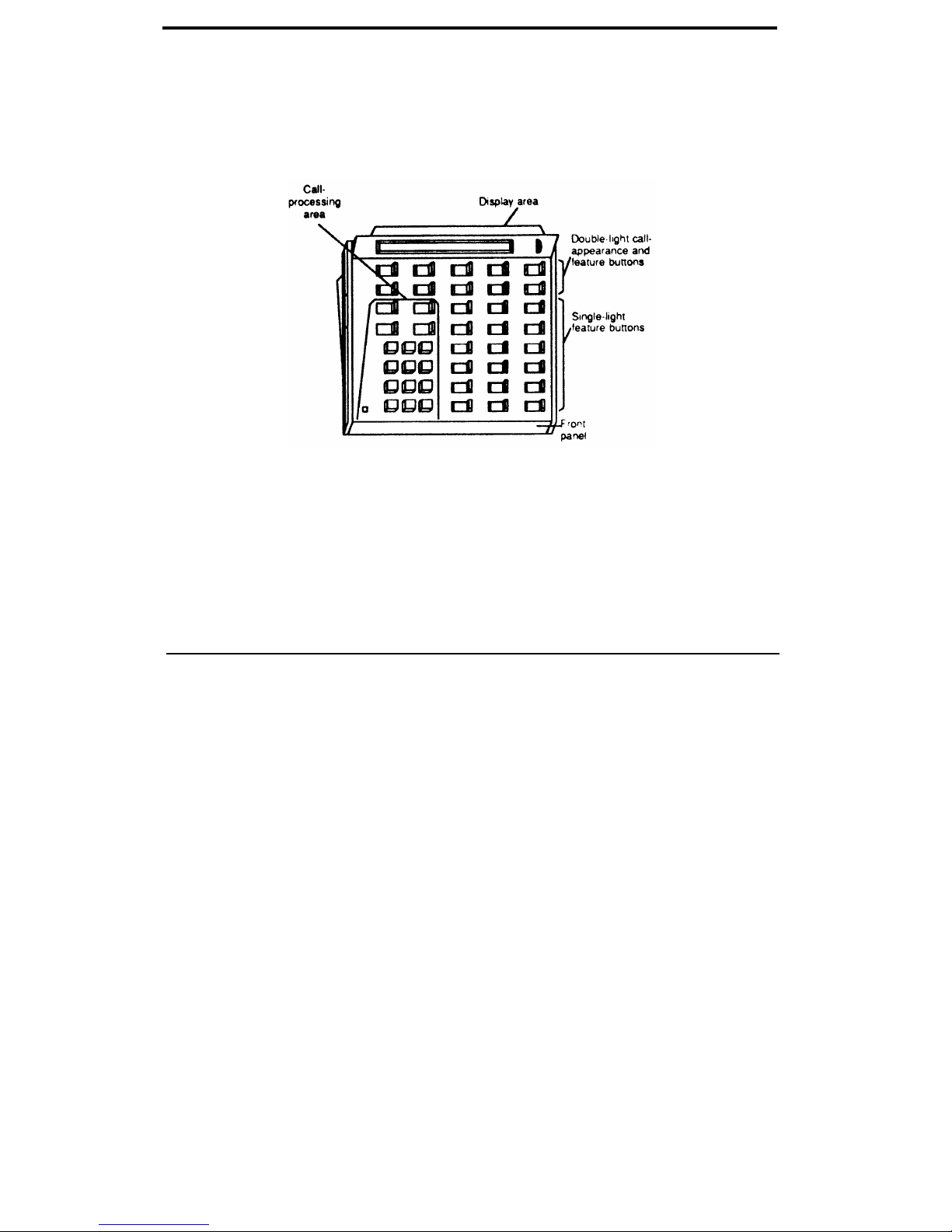
Physical Description
The functional areas of the CALLMASTER digital voice terminal are shown in Figure 2
and described on the following pages.
Figure 2. CALLMASTER Digital Voice Terminal Functional Areas
Call-Processing Area
As shown in Figure 3, this area contains the following:
Dial pad
Conference button
Transfer button
Drop button
Hold button
Message light
Use the touch-tone buttons, 1 through #, to dial calls and
access features.
Use to set up conference calls with 3 people (DEFINITY
Generic 2 and System 85) or up to 6 people (DEFINITY
Generic 1 and System 75).
Use to send a call to another extension or outside number.
Use to end one call, immediately obtain dial tone, and place
another call; also, use to drop the last person added to a
conference call.
Use to put a call on hold.
Goes on when a message is waiting.
3
Page 7
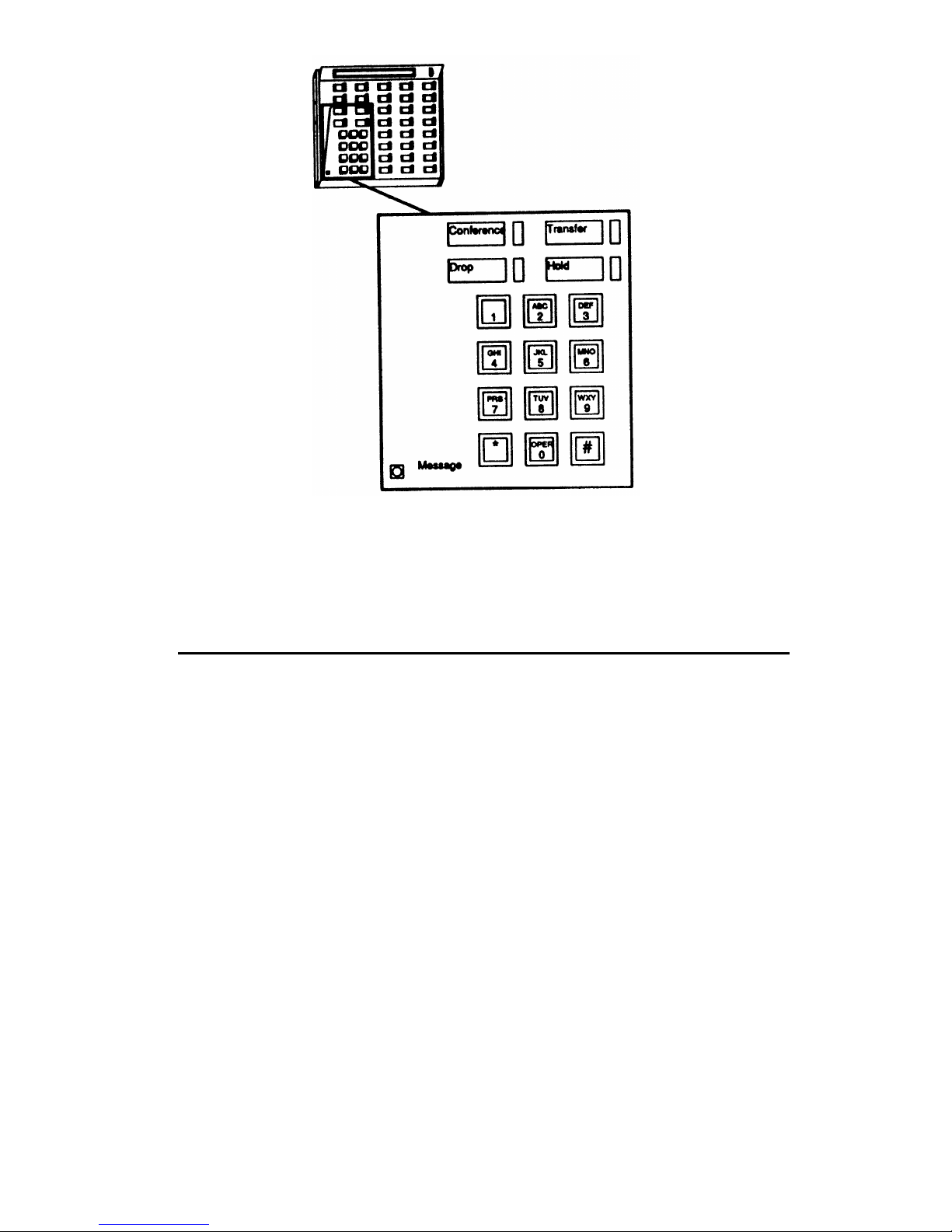
Figure 3. Call-Processing Area
Display Area
As shown in Figure 4, this area contains an alphanumeric display and a display
contrast-control wheel.
The 2-line, 40-character-per-line, alphanumeric display shows call- and system-related
information, including incoming and outgoing calls.
The person who manages your system may assign several display-mode buttons to
your voice terminal. These display modes are discussed in AT&T System 75 Automatic
Call Distribution Agent Instructions
(555-200-722) and
AT&T DEFINITY™ Generic 2 and
System 85 Automatic Call Distribution Agent Instructions
(555-104-713).
The contrast-control wheel rotates up to make the display darker and down to make
the display lighter.
4
Page 8

Figure 4. Display Area
Double-Light Call-Appearance and Feature Buttons
The 10 buttons shown in Figure 5 can be administered by the person who manages
your system for use as call appearances or for feature activation and deactivation.
Each button has a label, a red light and a green light.
Figure 5. Double-Light Call-Appearance and Feature Buttons
5
Page 9

Single-Light Feature Buttons
The 18 buttons shown in Figure 6 are arranged in 3 columns of 6 buttons. Each button
has a label and a green light. The last button in the first column is preprogrammed as
the [
Mute ] button. You can use the [ Mute ] button when you are active on a call and
want to speak, perhaps to someone near you, without being overheard by the caller.
Operation of the [
Mute ] button is described on page 12.
The person who manages your system can administer the remaining 17 buttons to
activate and deactivate features or to perform special functions. One of these buttons
will be administered as a [
Release ] button, which is necessary for proper ACD
operation. You must press [
Release ] to return to normal mode:
●
●
After every call.
If power is removed or after any service-affecting maintenance test has been run on
your switch.
When you press [
Release ], a dial tone will not be returned.
Figure 6. Single-Light Feature Buttons
6
Page 10

Front Panel
As shown in Figure 7, the front panel drops down to reveal:
Instructions for
button-label strips
Self-test button
1-2 switch
Ringer-volume control
Follow these instructions to remove or insert button-label
strips for call-appearance and feature buttons. (These strips
will probably be labeled for you. However, if they are not,
or if you need to change a label, you can remove the strips
and write or type on them.)
Use to test the lights, ringer, and display.
1
Gently pull down on the front panel to open it.
2
Press and hold the self-test button. If all is well, the
ringer sounds, the lights go on (one field of lights at a
time), and the display shows 80 discrete blocks.
3
Release the button. The ringer stops, the active lights
go off, and the display returns to its former state.
This switch is set by the installer; you should not change the
switch setting.
Move the control to the right to increase the ringer volume
and to the left to decrease the volume.
Figure 7. Front Panel
7
Page 11

Sides and Back of the Terminal
One side and the back of the terminal are shown in Figure 8. Each side of the terminal
contains a headset jack and a screw hole.
Side jacks
A headset or handset (with special adapters) can be plugged
into the jacks on each side of the terminal. Both
hand/headsets can be used at once.
Screw holes
Optional handset cradles can be attached using the screw
holes on each side of the terminal and an available handset
kit. Note: Handsets are not normally used with ACD
operations; the handset kit will not allow you to go off-hook.
An optional kneewell adapter may be plugged into the jack
on the back of the teminal. The adapter attaches under the
desk to eliminate cord clutter. You can plug 2 headsets or 2
handsets into the adapter; the 2 headsets or 2 handsets must
both be the same model.
Back jack
To connect the kneewell adapter to the terminal:
1
2
Locate the jack on the back of the terminal.
Plug in the cord from the kneewelladapter.
The use of a kneewell adapter brings the number of available
headset jacks to 4; however, only 2 jacks should be used at
one time.
Model number
The model number tells you whether your terminal is a
model 602D1 or a model 602A1. Model 602D1 is equipped
with a recorder interface module (RIM) that enables the
recording of all voice interactions. Model 602A1 does not
have a RIM. If there is not a model number, your terminal is
a model 602A1.
Figure 8. Side and Back of the Terminal
8
Page 12

Bottom of the Terminal
As shown in Figure 9, a line jack is located on the bottom of the terminal. The line
jack is used to connect the voice terminal to a wall telephone jack.
Figure 9. Bottom of the Terminal
9
Page 13

Features
Many features are available for use with your CALLMASTER voice terminal. Because
no organization can use all of the available features, each organization must choose
those that best suit its needs. After the choices have been made, the person within
your organization who manages your telecommunication system must do any
necessary administration and label the feature buttons on individual voice terminals.
This System Manager can tell you how to use the features that have been administered
for your particular CALLMASTER voice terminal. All CALLMASTER voice terminals
have 5 fixed features — Conference, Drop, Hold, Mute, and Transfer. These 5 features,
listed alphabetically, are discussed below.
Conference
To add another party
1
to an existing call (for a
total of up to 3 parties
in DEFINITY Generic 2
and System 85 or 6
parties in DEFINITY
Generic 1 and System
2
75)
3
4
Press [
Conference ]
●
Present call is put on hold; all other parties remain
connected to each other
●
You are given a new call appearance and hear dial
tone
Dial number of new party and wait for answer
●
If party answers, explain who’s on the conference call
and go to step3
●
If party does not answer or if line is busy, press
fluttering
xxxx to return to held call
Press [
Conference ] again
●
All parties are now connected
Repeat from step 1 to add another party to the
conference call
10
Page 14

To add a call you have
put on hold to another
call you are connected
to
1
2
3
Press [
Conference ]
●
●
●
Green light at held call appearance continues to
flutter
Green light at current call appearance also flutters
You are given a new call appearance and hear dial
tone
Press
xxxx of held call (first call)
Press [
Conference ] again
Drop
To disconnect from an 1
Press [
Drop ]
active 2-party call
● Hear dial tone
Note: You may press [
Release ] instead of [ Drop ] to
disconnect faster. You will not hear dial tone.
To drop the last party 1
Press [
Drop ]
you added to a
●
Last party added to Conference call is dropped; you
conference call
and other parties remain connected
11
Page 15

Hold
To put a call on hold
1
Press [
Hold ]
while you answer
●
Green light at held call appearance flutters
another call, place a
call, or perform some
Note: If you put a conference call on hold, the other
other task
parties remain connected.
To answer a new call
1
Press [
Hold ]
while active on another
●
Green light at held call appearance flutters
can
2
Press
xxxx of incoming call
To return to held call
1
Press
xxxx of held call
Mute
To speak to someone
1
Press [
Mute ]
near you without being
Green light goes on; your voice is not transmitted
overhead by the caller
●
2
To reestablish 2-way transmission, press [
Mute ] again
●
Green light goes off; caller can now hear you
12
Page 16

Transfer
To send an existing call
Note: Only calls from another extension can be sent to
to another extension or
an outside number. You cannot transfer a call from an
outside number
outside number to another outside number.
1
Press [
Transfer ]
●
Green light at call appearance flutters
●
Present call is put on hold
●
You are given a new call appearance and hear dial
tone
2
Dial number where call will be transferred
● Hear ringback tone
●
If answered remain on line and announce call if
desired.
●
If not answered or if line is busy, return to held call
by pressing
xxxx where green light is fluttering
3
Press [
Transfer ] again
●
Call is transferred to dialed number
13
Page 17

References
●
●
●
●
●
●
AT&T System 85 CALLMASTER™ Digital Voice Terminal — Application Notes
(555-
103-523)
AT&T System 75 CALLMASTER™ Digital Voice Terminal — Application Notes
(555-
103-253)
AT&T DEFINITY™ Generic 2 and System 85 Automatic Call Distribution Supervisor
Instructions
(555 104 714)
AT&T System 75 Automatic Call Distribution Supervisor Instructions
(555-200-724)
AT&T DEFINITY™ Generic 2 and System 85 Automatic Call Distribution Agent
Instructions
(555-104-713)
AT&T System 75 Automatic Call Distribution Agent Instructions
(555-200-722)
14
Page 18

555-015-716
Issue 4, February 1991
Graphics © 1988 AT&T
 Loading...