

Page 1
Display Messages
Screen Display: When:
PRIVATE NAME
PPP
PRIVATE CALLER
UNKNOWN NAME
UUU
UNKNOWN CALLER
EXTENSION USED
1
Call Display 436
The other party is blocking name information.
The other party is blocking number information.
The other party is blocking both name and
number information.
Your phone company is unable to receive the
other party’s name information.
Your phone company is unable to receive the
other party’s number information.
Your phone company is unable to receive the
other party’s name and number information.
An extension phone on this line is being used,
so call information cannot be received.
USER’S MANUAL
Part 2
Revised 8/25/00
Fold open this manual for
information about this product’s
installation and operation. Please
also read Part 1 – Important
Product Information.
Para recibir este manual en español, por favor llame al 1 800 222-3111.
AT&T and the globe symbol are registered trademarks of AT&T Corp. licensed to Advanced American Telephones.
F.P.O.
NEED 436 MODEL
© 2000 Advanced American Telephones. All rights reserved.
Printed in ?. xxxxxxxxx Issue 1AT&T 9/00
Page 2
Table/Desk Installation
1 Connect the line cord.
Plug one end of the line cord (supplied) into the unit’s TEL LINE jack.
Plug the other end of this cord into the modular wall jack, making sure it
snaps firmly into place. (If you are connecting an answering machine,
make sure it is connected between the unit and the telephone.)
2 Connect the power cord.
Plug one end of the power cord into the back of the unit. Plug the
other end into a 110V electrical outlet not controlled by a wall switch.
3 Connect the unit to the telephone (optional).
Unplug the telephone’s line cord from the wall jack and plug it into
the unit’s TEL SET jack.
4 Connect the base as shown.
5 See “Installation Settings.”
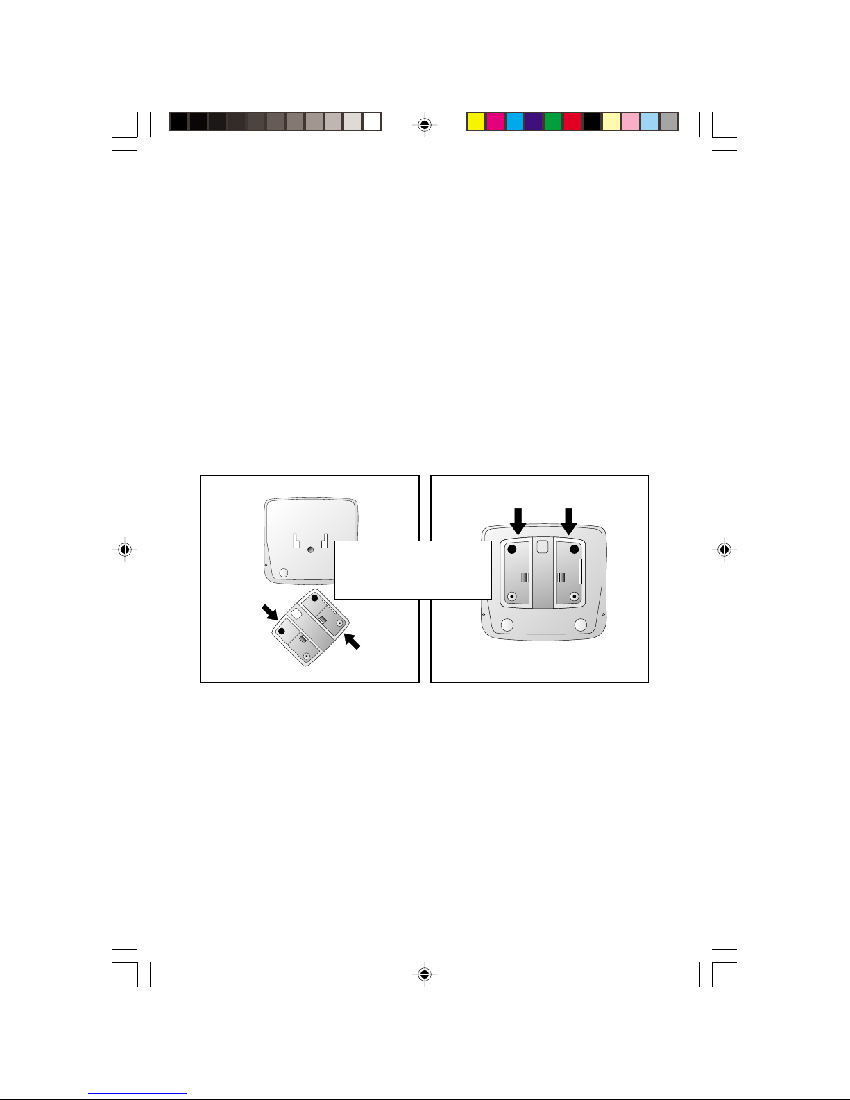
Base Installation For Table/Desk
F.P.O.
NEED 436 MODEL
1
Page 3

Table/Desk Installation
Standard
Electrical
Outlet
F.P.O.
NEED 436 MODEL
Telephone
Installation With Answering System
Standard
Electrical
Outlet
Modular
Wall Jack
Caller ID Unit
Caller ID Unit
F.P.O.
NEED 436 MODEL
Telephone
NOTE: Use with a telephone is optional. However, if you do not connect a
telephone, you will not be able to use the Display Dial feature (described later
in this manual). If this unit is connected to an answering system, and if you
subscribe to Call Waiting, the Call Waiting signal may cut off some messages.
Answering
System
2
Modular
Wall Jack
Page 4
Wall Installation
F.P.O.
NEED 436 MODEL
1 Remove the bracket by sliding it downward from the unit.
2 Hold the flat edge of the bracket against the wall with the
rubber feet towards the bottom of the unit. Mark the location of
the two mounting screw holes with a pencil.
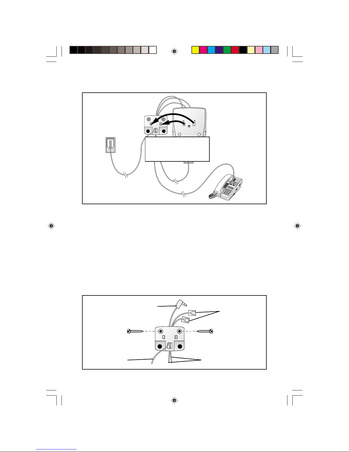
3 Thread the power cord through the square hole at the bottom
center of the bracket.
4 Hold the bracket against the wall with the power cord and the
two telephone cords routed through the channel on the back
top center of the bracket (use only one line cord if you’re not
connecting a phone). Only the telephone line cord(s) should be routed
through the bottom of the bracket channel. Using the appropriate wall
screw for your wall type, screw the bracket into the wall.
Power Cord
Power Cord
Telephone
Line Cords
Telephone
Line Cords
3
Page 5

Wall Installation
(continued from page 3)
5 Snap the unit onto the bracket and slide it down as far as
it will go.
6 Plug the power cord into the back of the unit.
7 Plug one telephone line cord into the TEL SET jack and one line
cord into the TEL LINE jack. Pull the excess cord to the bottom of
the set.
8 Connect the other end of the cord connected to the TEL LINE
jack to a modular wall jack.
9 Connect the other end of the cord connected to the TEL SET
jack to a telephone (optional).
10 If you’re connecting the unit to an anwering system, make sure
the answering system is connected between the unit and the
telephone.
11 Plug the power cord into an electrical outlet not controlled by
a wall switch.
12 See “Installation Settings.”
4
Page 6

Installation Settings
Language Selection
You can select ENGLISH or ESPANOL (Spanish) as the language in which
your Caller ID information is displayed. When you first plug in the power
cord, the screen displays WHICH LANGAUGE?.
1 Press + until the screen displays your language selection.
2 Press N. You will see the Home Area Code setup screen.
Set Home Area Code
You’ll need to program your area code, so your phone can properly
recognize and dial calls.
If for calls within You dial Enter in Step 2
your area code 7 digits Your home area code
(phone number, no area code)
10 digits 000
(area code + phone number)
— OR —
11 digits
(1 + area code + phone number)
1 Press N until the screen displays:
HAC-___
HOME AREA CODE?
2 Press + until the screen displays the first digit of your area code.
3 Press D.
4 Repeat Steps 2 and 3 for the second and third digits of your area code.
5 Press N.
5
Page 7

Installation Settings
Set Local Area Code
If for You dial Enter in Step 2
All calls outside 11 digits No Local Area Codes
your area code (1 + area code + phone number)
Some calls outside 10 digits Area codes that do
your area code (area code + phone number) not require a "1"
If you dial 10 digits (area code plus phone number) for calls within your own area
code, include your area code as a Local Area Code.
1 Press and release N until the screen diplays:
LAC1-___
LOCL AREA CODE?
2 Press + until the screen displays the first digit of your area code.
3 Press D.
4 Repeat Steps 2 and 3 for the second and third digits of your area code.
5 Press Dto program another Local Area Code, then follow
Steps 2 through 5
— or —
Press Nto save and exit.
In addition to making a Language Selection, and setting Home and Local
Area Codes, you can customize other operations of the Caller ID now or
later (see “Choosing Display Options”).
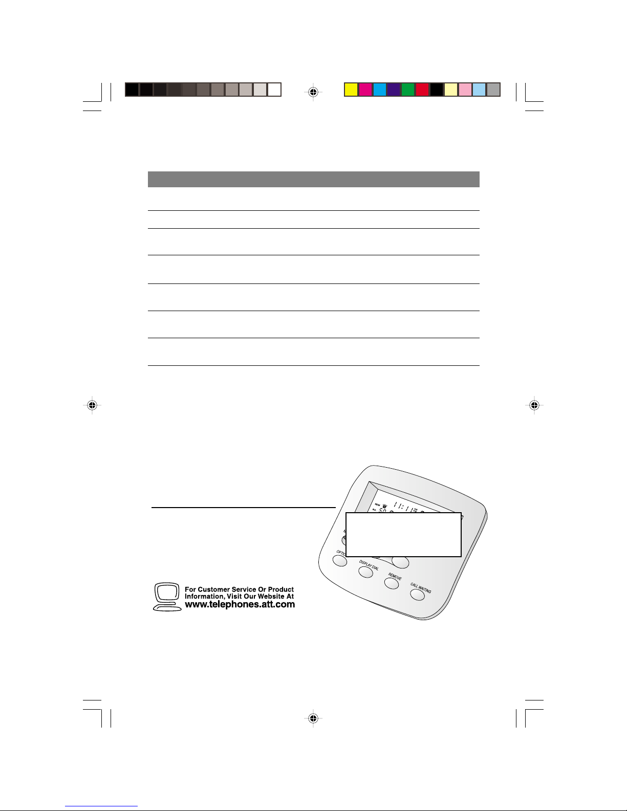
Buttons and Screen Indicators
Indicates AM or PM
F.P.O.
Remove a call from
call history
6
Message Waiting
Indicates
unreviewed call
information
Position of call
in call history
Flashes if you have
unreviewed call
information
Customize features
Time call was received
NEED 436 MODEL
Dial number displayed
on screen
Date call was
received
Caller’s
telephone
number
Caller’s name
Scroll through
Call List and
select options
Access Call
Waiting
Page 8

About Caller Identification (Caller ID)
This product has a Caller ID with Call Waiting feature that works with
service from your local phone service provider.
Caller ID with Call Waiting lets you see who’s calling before you answer
the phone, even when you’re on another call.
You may need to change your phone service to use this feature. Contact
your phone service provider if:
• You have both Caller ID and Call Waiting, but as separate services
(you may need combined service)
• You have only Caller ID service, or only Call Waiting service
• You don’t subscribe to any Caller ID or Call Waiting services.
You can use this product with regular Caller ID service, and you can use
this product’s other features without subscribing to either Caller ID or
combined Caller ID with Call Waiting service.
There are fees for Caller ID services, and they may not be available in all
areas.
This product can provide information only if both you and the caller are in
areas offering Caller ID service, and if both telephone companies use
compatible equipment.
About Call History
This phone assigns each incoming call a number from 1 to 90. The most
recent call will have the highest number. When the memory is full, the
oldest call information is deleted to make room for new incoming call
information.
If you answer a call before call information appears on the screen, it will
not be in the call history.
7
Page 9

Operation
Reviewing Call History
The screen displays the call information for about 30 seconds after it has
been received.
1 To review earlier calls, press -.
2 To advance through call history from an earlier call, press +. The
screen displays END OF LIST to indicate you have reviewed all the
calls in the call history. When you reach the end of the call history,
it begins again.
Removing Call Records from History
When the unit is idle, press r to erase a displayed call record. The
screen displays Call Removed. To remove all calls from call history, press
r when no call is displayed. The screen displays REMOVE All?.
Press r again.
NOTE: Once a call is removed from call history, it cannot be retrieved.
Call Waiting
Press Con the unit when you receive a call waiting signal.
Using this button puts your current call on “hold,” connects you to the
new call, and displays the name/number of the call waiting call on the
bottom two lines.
Press Cagain to return to the first call. Use Cinstead of
using the switchhook or Flash button on your phone.
8
Page 10

Operation
Display Dial
As you review calls in history, you can dial a displayed phone number.
(This feature works only with touch tone service on a phone connected
to the unit.) Lift the handset of the phone (the screen displays the first
number in the call history), then press and release D to call that
number, or press + or - to scroll to another number in the call history.
After you press D, the screen shows the number being called.
If the screen displays Call ID Error, an error is preventing use of the
Display Dial feature.
Display Dial Options
Use this feature if you want to check and/or change the way a number in
call history is dialed.
1 Press + or - to locate the number you want to call.
2 Press D to make the call
— OR —
Press N to see choices of how the number can be dialed (without
“1” or the area code, with “1” but no area code, with an area code but
no “1,” or with “1” followed by the area code).
The displayed number is the currently selected method. Use + or if you need to select another choice, then press D to make
the call.
9
Page 11

Choosing Display Options
You can customize how the features of this product work. Press N,
then use + or - to scroll through display choices. Press N again
when the desired choice is displayed — this sets your selection and
automatically moves you to the next option. You must make a selection
within 30 seconds or the unit returns to standby. When you have finished
setting options, wait 30 seconds for the unit to return to standby.
Asterisk (*) indicates default setting.
Option: Choice:
WHICH LANGUAGE?
ENGLISH
ESPANOL
HOME AREA CODE
HAC-___
LOCL AREA CODE
LAC1--___
Call History
ALL CALLS*
NO CALLS
UNANS. CALLS
Repeat Calls
COMBINED
SEPARATE*
Call List Order
NEW CALLS*
BY TIME
Caller ID with Call Waiting
SET CID/CW
ON*
OFF
Contrast
1 2* 3 4
Choose whether displays appear in
English or Spanish.
Set the unit to recognize calls from your
area code.
Program up to four area codes that do not
require dialing a "1" before them.
Choose how incoming calls are stored in
call history.
The call history stores all calls received in
order.
No new calls will be added to call history.
Only unanswered calls will be added to
call history.
Choose how repeat calls are stored and
displayed.
Repeat information is stored with original
information; time/date reflect most recent
calls.
Repeat information is listed separately.
Choose in what order calls are displayed.
Unreviewed information is displayed first.
Calls are displayed in the order received.
Set the Call Display to ON for Type II
(operates with Call Waiting display) or
OFF for Type I (operates without Call
Waiting display) service.
Adjust screen lighting to a comfortable
level, from 1 (light) to 4 (dark).
10
Page 12

In Case Of Difficulty
If you have difficulty operating this product, try the suggestions below.
For Customer Service, visit our website at www.telephones.att.com or call
1 800 222-3111. Please retain your receipt as your proof of purchase.
If the NEW CALL light remains on:
Unplug the power cord for 10 seconds, then plug it back in.
If the screen displays Extension Used, and none are:
Check all line cord connections. Make sure the line cord from the
modular wall jack is connected to the TEL LINE jack and, if you’re
connecting a telephone, that the line cord from the phone is connected
to the TEL SET jack.
If the screen is blank:
• Make sure all power and line cords are correctly connected.
• The unit does not display the time and date until the first call is
received.
• You must have combined Caller Identification with Call Waiting
(Type II) service from your local telephone company.
If the ERR is flashing or the screen displays LINE ERROR:
The unit has received incomplete or corrupted caller identification
information from the telephone company. The unit will display as much
information as possible.
If you hear a loud click at your phone when you press D:
This is normal operation for the unit.
11
 Loading...