

Page 1

AT&T Business in a Box®
Quick Start Guide
© 2014 AT&T Intellectual Property. All rights reserved. AT&T, Globe logo and other marks are trademarks of AT&T Intellectual Property.
Please ensure that you have set-up the equipment before the date scheduled
with your AT&T Order Manager for Test and Turn Up of your service
Page 2
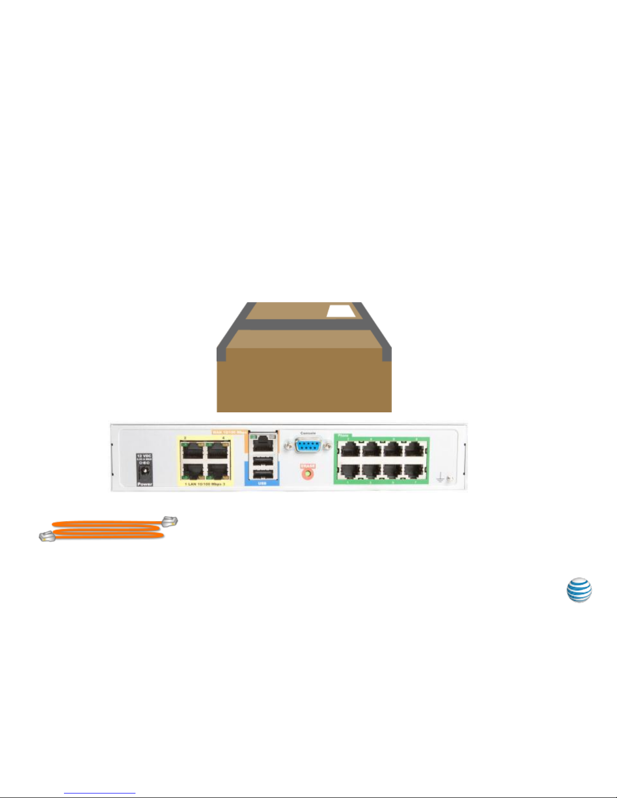
If required, up to three 8 Port Analog Telephone Adapter(s) (ATA) will be
included in your router package. Each device will provide 8 additional analog
ports to connect to your phone system.
What’s in the Box
2
AT&T Business in a Box® ATA Add-On
© 2014 AT&T Intellectual Property. All rights reserved. AT&T, Globe logo and other marks are trademarks of AT&T Intellectual Property.
RJ45 Straight Through Ethernet
Labelled ISE1015-010
Additional Components:
• Power Adapter/Cable
• Rack Mount Brackets with 8 screws
• Cable Tie and Self Adhesive Cable Tie base
Page 3
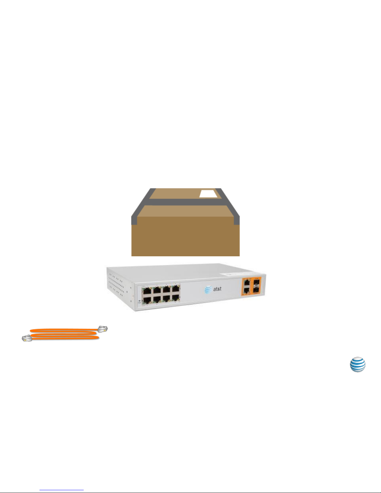
If required, up to three 8 Port POE switch(s) will be included in your router
package. Each device will be used to provide 8 additional Ethernet switch
ports for your PC’s, Printers, Servers, etc.
What’s in the Box
3
© 2014 AT&T Intellectual Property. All rights reserved. AT&T, Globe logo and other marks are trademarks of AT&T Intellectual Property.
AT&T Business in a Box® 8 Port POE Add-On
RJ45 Straight Through Ethernet
Labelled ISE1015-010
Additional Components:
• Power Adapter/Cable
• Rack Mount Brackets with 8 screws
• Cable Tie and Self Adhesive Cable Tie base
Page 4

If required, up to three 24 Port POE switch(s) will be included in your router
package. Each device will be used to provide 24 additional Ethernet switch
ports for your PC’s, Printers, Servers, etc.
What’s in the Box
4
© 2014 AT&T Intellectual Property. All rights reserved. AT&T, Globe logo and other marks are trademarks of AT&T Intellectual Property.
AT&T Business in a Box® 24 Port POE Add-On
RJ45 Straight Through Ethernet
Labelled ISE1015-010
Additional Components:
• Power Adapter/Cable
• Rack Mount Brackets with 8 screws
• Cable Tie and Self Adhesive Cable Tie base
Page 5

Understanding your AT&T Business in a Box® Equipment
5
Ethernet LAN Ports (12 or 24)
AT&T Provided Interconnect cables for Add-on’s when
ordered will connect to these ports.
AT&T Business in a Box® 12 or 24 Port Base Unit Router (24 port depicted) is
always included in your initial shipment. Add-on devices will connect directly
to the Ethernet Ports. Instructions will be provided in the shipping box as to
which Add-on device will connect to which Ethernet port.
© 2014 AT&T Intellectual Property. All rights reserved. AT&T, Globe logo and other marks are trademarks of AT&T Intellectual Property.
Page 6

The AT&T Business in a Box® Add-On’s may be wall mounted on a
¾” or thicker plywood backing. Use the two (2) rack-mount
brackets, eight (8) bracket screws (included) and four (4) 1 ½”
wood screws (not included).
Complete the following steps:
1) Position the device so that the front panel is facing down
and apply the rack-mount brackets with bracket screws to
each side as shown in Figure 1. Rack-mount bracket
position.
2) Attach the bracket to ¾” or thicker plywood backing using
four (4) 1 ½” wood screws as shown in Figure 2. RackMount bracket on plywood backing.
Important: Cables will flow down and should be dressed using a
wire minder. The unit should be mounted high enough that the
technician can see the status lights**. See Figure 3 Installation
example.
Step 1 – Wall Mounting Instructions (optional to Rack Mounting)
6
** It is recommended, but not required that a skilled technician mount the router on the wall.
© 2014 AT&T Intellectual Property. All rights reserved. AT&T, Globe logo and other marks are trademarks of AT&T Intellectual Property.
Page 7

Step 2 - Attach Power Cord to the Add-on (ATA Depicted)*
7
Plug in power cord to the Add-on device
To power strip,
UPS or other
power source
© 2014 AT&T Intellectual Property. All rights reserved. AT&T, Globe logo and other marks are trademarks of AT&T Intellectual Property.
* Note: Each of the three Addon types will require external
power. This example is for the
ATA Add-on device. Power
adapter type may be different
for the POE Add-on devices.
Page 8

Step 3 - Connect the Add-on to the Base Unit (ATA Depicted)*
Connect the Add-on device to the Base Unit using the provided cable.
Instructions will be provided as to which Add-on device will connect to
which Ethernet port on the Base Unit Router.
8
© 2014 AT&T Intellectual Property. All rights reserved. AT&T, Globe logo and other marks are trademarks of AT&T Intellectual Property.
Interconnect
Included Orange cable to orange ports
* Note: The same
method will be utilized to
connect additional ATA’s
and/or the 8 or 24 Port
POE Add-on devices if
required.
Page 9

Step 4 - Connect Your device(s) to the Add-on’s
Connect your Key System or Ethernet devices using customer provided
cables to the Add-on Devices
9
© 2014 AT&T Intellectual Property. All rights reserved. AT&T, Globe logo and other marks are trademarks of AT&T Intellectual Property.
Connect your analog
phones/Key System to the
green ports on the right
using RJ11 cables
Connect your Ethernet
devices to the Ethernet
switch ports on the left
using RJ45 cables.
 Loading...