

Features
• Active Mixer with Conversion Gain
• No External LO Driver Necessary
• Low LO Drive Level Required
• RF and LO Ports May Be Driven Single-ended
• Single 5-V Supply Voltage
• High LO-RF Isolation
• Broadband Resistive 50-Ω Impedances on All Three Ports
• Small SSO16 Package
Applications
• Digital Communication Systems
• 2200 MHz to 2700 MHz Transceivers for Base Stations
Electrostatic sensitive device.
Observe precautions for handling.
Description
The T0782 is a high-linearity active mixer which is manufactured using Atmel’s
advanced Silicon-Germanium technology. This mixer features a frequency range of
2200 MHz to 2700 MHz. It operates from a single 5-V supply and provides 10 dB of
conversion gain while requiring only 0 dBm input to the integrated LO driver. An IF
amplifier is also included.
The T0782 incorporates internal matching on each RF, IF and LO port to enhance
ease of use and to reduce the external components required. The RF and LO inputs
can be driven differentially or single-ended.
2200-2700 MHz
High Linearity
SiGe Active
Receive Mixer
T0782
Preliminary
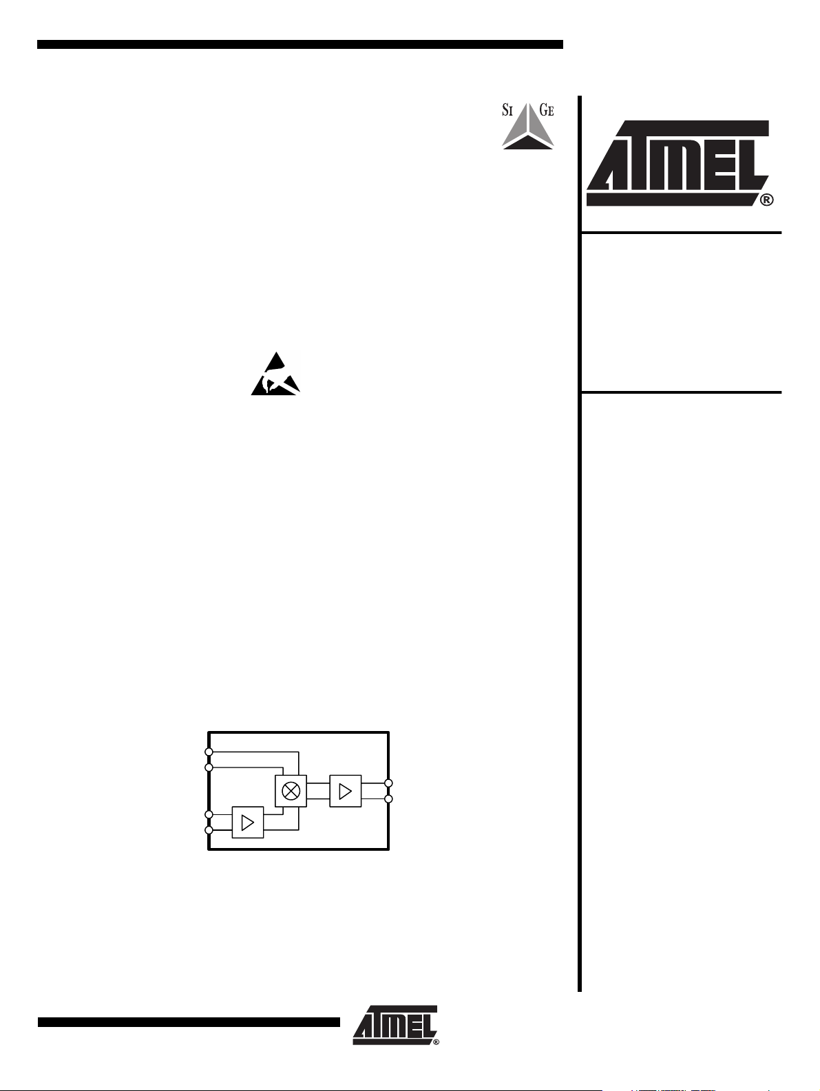
Figure 1. Block Diagram
RFP
RFN
LOP
LON
4
13
12
5
1
IFP
16
IFN
Rev. 4526A–SIGE–03/02
1
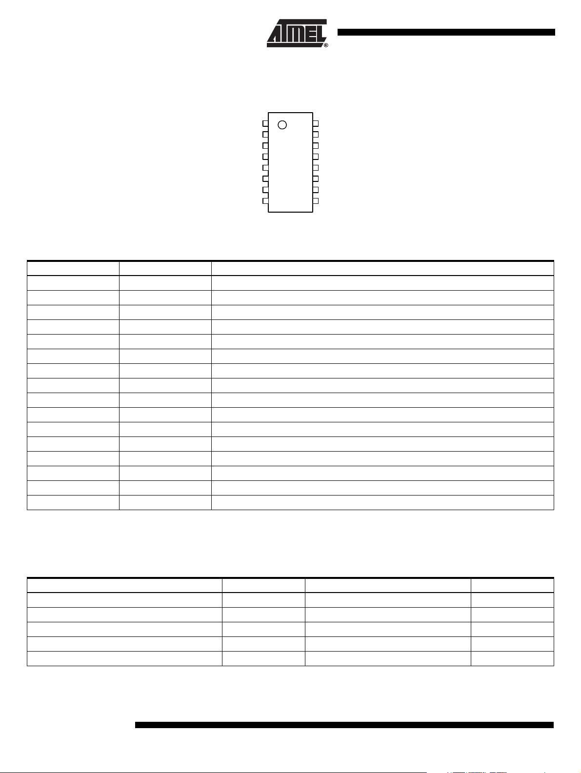
Pin Configuration
Figure 2. Pinning SSOP16
Pin Description
Pin Symbol Function
1 IFP IF positive output
2 VCC 5-V power supply
3 GND Ground
4 RFP RF positive input
5 RFN RF negative input
6 GND Ground
7 VCC 5-V power supply
8 L1 External inductor terminal
9 L2 External inductor terminal
10 VCC 5-V power supply
11 G ND Ground
12 LON Local oscillator, negative input
13 LOP Local oscillator, positive input
14 GND Ground
15 VCC 5-V power supply
16 IFN IF negative output
IFP
VCC
GND
RFP
RFN
GND
VCC
L1
1
2
3
4
5
6
7
8
16
15
14
13
12
11
10
IFN
VCC
GND
LOP
LON
GND
VCC
L2
9
Absolute Maximum Ratings
All voltages are referred to GND
Parameters Symbol Value Unit
Supply voltage V
LO input LO
IF input RF
Operating temperature T
Storage temperature T
2
T0782
CC
, LO
P
, RF
P
OP
stg
N
N
5 to 6.0 V
10 dBm
15 dBm
-40 to +85 °C
-40 to +150 °C
4526A–SIGE–03/02
Thermal Resistance
Parameter Symbol Value Unit
Junction ambient R
thJA
TBD K/W
Electrical Characteristics
T0782
Test conditions: Vcc = +5 V, T
= +25°C
amb
RF input: –20 dBm at 2450 MHz
LO output: 0 dBm at 2250 MHz
No. Parameters Test Conditions / Pins Pin Symbol Min. Typ. Max. Unit Type *
AC Performance
Frequency range f 2200 2700 MHz
IF frequency range F
IF
Output IP3 RF1 = RF2 = –17 dBm/tone IP3 15.5 dBm
Output P1dB 4.5 dBm
Conversion gain 10.5 dB
SSB noise figure 15.5 dB
RF return loss 14 dB
LO return loss 14 dB
IF return loss 14 dB
LO drive –30+3dBm
Isolation Performance
Leakage (LO-RF) –30 dBm
Leakage (LO-IF) –30 dBm
Miscellaneous
Supply voltage V
Supply current I
CC
CC
*) Type means: A = 100% tested, B = 100% correlation tested, C = Characterized on samples, D = Design parameter
10 200 300 MHz
4.75 5 5.25 V
150 mA
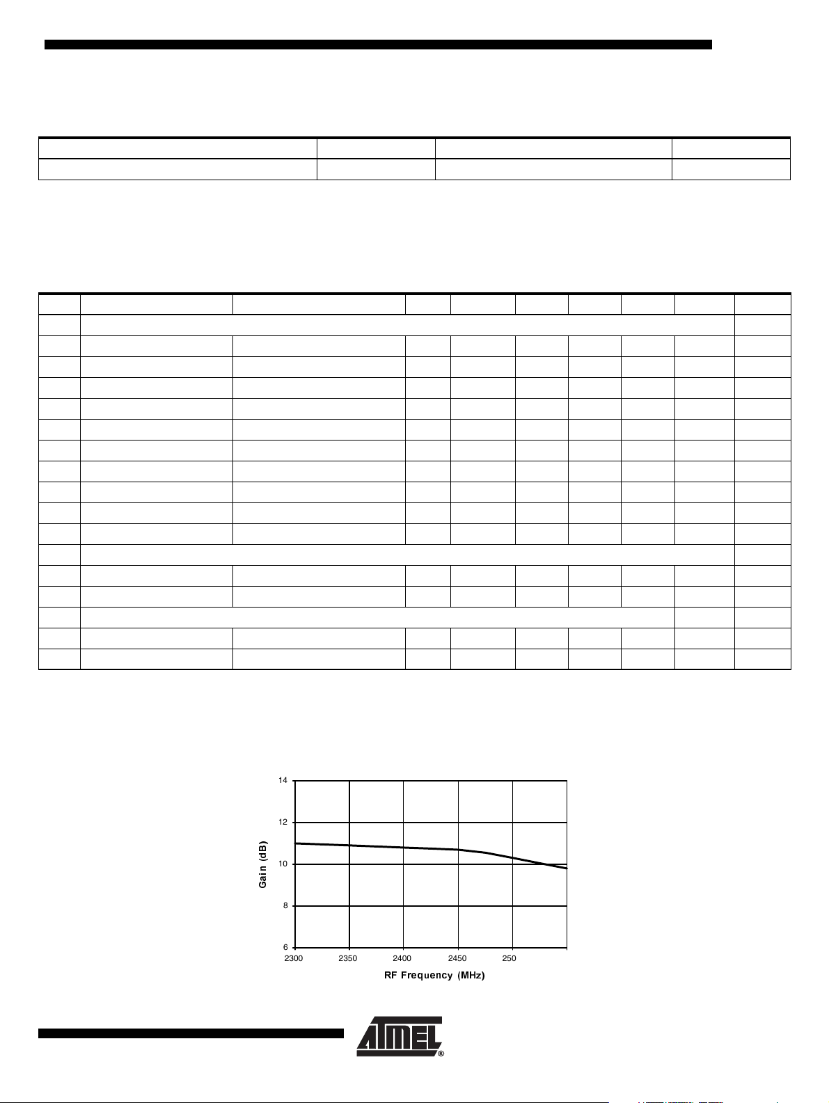
Typical Device Performance
Figure 3. Conversion Gain versus RF Frequency, VCC = 5.0 V, LO = 0 dBm, RFIN = –20 dBm, IF = 200 MHz
14
12
%
G
10
Q
L
D
*
8
6
2300 2350 2400 2450 2500 2550
5))UHTXHQF\0+]
4526A–SIGE–03/02
3

Figure 4. Return Loss versus RF Frequency, VCC = 5.0 V
0
-10
E
G
-20
V
V
R
/
Q
-30
U
X
W
H
5
-40
-50
2300 2350 2400 2450 2500 2550
5))UHTXHQF\0+]
Figure 5. Return Loss at LO Input, V
= 5.0 V
CC
0
-10
E
G
-20
V
V
R
/
Q
-30
U
X
W
H
5
-40
-50
2000 2100 2200 2300 2400 2500
Figure 6. Return Loss versus IF Frequency, V
0
5
E
G
10
V
V
R
/
Q
15
U
X
W
H
5
20
= 5.0 V
CC
/2)UHTXHQF\ 0+]
25
150 175 200 225 250
,))UHTXHQF\0+]
4
T0782
4526A–SIGE–03/02

Figure 7. Demo Test Board Schematic
5V
Lfil
Vcc
Vcc
C4
RFin
J3
Vcc
C3
C5
R1
R2
C20
Vcc
IFout
J5
T2
C7
IC1
1
2
3
4
5
6
7
8
L1 L2
16
15
14
13
12
T0782
11
10
9
C9
C21
Vcc
L4
R3
R4
T0782
C1
Vcc
C11
LOin
J4
C12
Vcc
C6
C10
Bill of Material
Component Designator Value Vendor Part Number Description
IC1 Atmel T0782 SiGe receiver mixer
J3, J4, J5 Johnson
Components
T2 1:1 Mini-circuits TC1-1 IF transformer
Lfil 1 µH Inductor, 1210 footprint, minimum 200 mA rating
L1, L2 100 nH TOKO LL1608-FSR10J Inductor, 0603 footprint, high Q series
C1, C3, C20, C21 5.6 pF Capacitor, 0603 footprint
C6, C10 100 pF Capacitor, 0603 footprint
C7, C9 120 pF Capacitor, 0603 footprint
C4, C5 1.2 pF Capacitor, 0603 footprint
C11, C12 1.5 pF Capacitor, 0603 footprint
R1, R2, R3, R4 0 Ω Resistor, 0603 footprint
L4 27 nH Inductor, 0603 footprint
142-0701-851 SMA connector, end launch with tab, for
0.062 inch thick board
4526A–SIGE–03/02
5

Figure 8. Demo Test Board (Fully Assembled PCB)
J5
47 mm
J3
Figure 9. Recommended Package Footprint
31.75
6.35
0.4
T2
C9
C7
C3
T9
C4
C5
C20
C1
IC1
C11
L3
T0782
L1
T11
L4
C12
C21
L2
C10C6
Lfil
CON
2 1
J4
47 mm
3.0
0.74
0.74
3.0
φ0.33 via
6.9
- Indicates metalization - vias connect pad to underlying ground plane
all units are in mm
0.7
0.9
Remark: heatslug must be soldered to GND.
6
T0782
4526A–SIGE–03/02

Ordering Information
Extended Type Number Package Remarks
T0782 SSOP16
Package Information
T0782
4526A–SIGE–03/02
7

Atmel Headquarters Atmel Operations
Corporate Headquarters
2325 Orchard Parkway
San Jose, CA 95131
TEL 1(408) 441-0311
FAX 1(408) 487-2600
Europe
Atmel Sarl
Route des Arsenaux 41
Casa Postale 80
CH-1705 Fribourg
Switzerland
TEL (41) 26-426-5555
FAX (41) 26-426-5500
Asia
Atmel Asia, Ltd.
Room 1219
Chinachem Golden Plaza
77 Mody Road Tsimhatsui
East Kowloon
Hong Kong
TEL (852) 2721-9778
FAX (852) 2722-1369
Japan
Atmel Japan K.K.
9F, Tonetsu Shinkawa Bldg.
1-24-8 Shinkawa
Chuo-ku, Tokyo 104-0033
Japan
TEL (81) 3-3523-3551
FAX (81) 3-3523-7581
Memory
Atmel Corporate
2325 Orchard Parkway
San Jose, CA 95131
TEL 1(408) 436-4270
FAX 1(408) 436-4314
Microcontrollers
Atmel Corporate
2325 Orchard Parkway
San Jose, CA 95131
TEL 1(408) 436-4270
FAX 1(408) 436-4314
Atmel Nantes
La Chantrerie
BP 70602
44306 Nantes Cedex 3, France
TEL (33) 2-40-18-18-18
FAX (33) 2-40-18-19-60
ASIC/ASSP/Smart Cards
Atmel Rousset
Zone Industrielle
13106 Rousset Cedex, France
TEL (33) 4-42-53-60-00
FAX (33) 4-42-53-60-01
Atmel Colorado Springs
1150 East Cheyenne Mtn. Blvd.
Colorado Springs, CO 80906
TEL 1(719) 576-3300
FAX 1(719) 540-1759
RF/Automotive
Atmel Heilbronn
Theresienstrasse 2
Postfach 3535
74025 Heilbronn, Germany
TEL (49) 71-31-67-0
FAX (49) 71-31-67-2340
Atmel Colorado Springs
1150 East Cheyenne Mtn. Blvd.
Colorado Springs, CO 80906
TEL 1(719) 576-3300
FAX 1(719) 540-1759
Biometrics/Imaging/Hi-Rel MPU/
High Speed Converters/RF Datacom
Atmel Grenoble
Avenue de Rochepleine
BP 123
38521 Saint-Egreve Cedex, France
TEL (33) 4-76-58-30-00
FAX (33) 4-76-58-34-80
Atmel Smart Card ICs
Scottish Enterprise Technology Park
Maxwell Building
East Kilbride G75 0QR, Scotland
TEL (44) 1355-803-000
FAX (44) 1355-242-743
e-mail
literature@atmel.com
Web Site
http://www.atmel.com
© Atmel Corporation 2002.
Atmel Corporation makes no warranty for the use of its products, other than those expressly contained in the Company’s standard warranty
which is detailed in Atmel’s Terms and Conditions located on the Company’s web site. The Company assumes no responsibility for any errors
which may appear in this document, reserves the right to change devices or specifications detailed herein at any time without notice, and does
not make any commitment to update the information contained herein. No licenses to patents or other intellectual property of Atmel are granted
by the Company in connection with the sale of Atmel products, expressly or by implication. Atmel’s products are not authorized for use as critical
components in life support devices or systems.
Atmel® is the registered trademark of Atmel.
Other terms and product names may by the trademarks of others.
Printed on recycled paper.
4526A–SIGE–03/02
xM
 Loading...