

Atmel STK521 User Manual

STK521
..............................................................................................
User Guide
8194B–AVR–01/12

Table of Contents
Section 1 1
Introduction 1
Features 2
Section 2 3
Using the STK521 Top Module 3
Connecting the Atmel STK521 to the Atmel STK500 Starter Kit 3
Powering the STK521 4
Programming the AVR 5
Atmel AVR JTAGICE mkII Connector 7
Atmel STK521 switches configuration 9
Atmel STK521 headers 10
Atmel STK521 test points 11
Extra functions 11
Section 3 12
Troubleshooting Guide 12
Section 4 13
Technical Specifications 13
Section 5 14
Technical Support 14
Section 6 15
Complete Schematics 15
STK521 User Guide 1-2
8194B–AVR–01/12
Section 1
Introduction
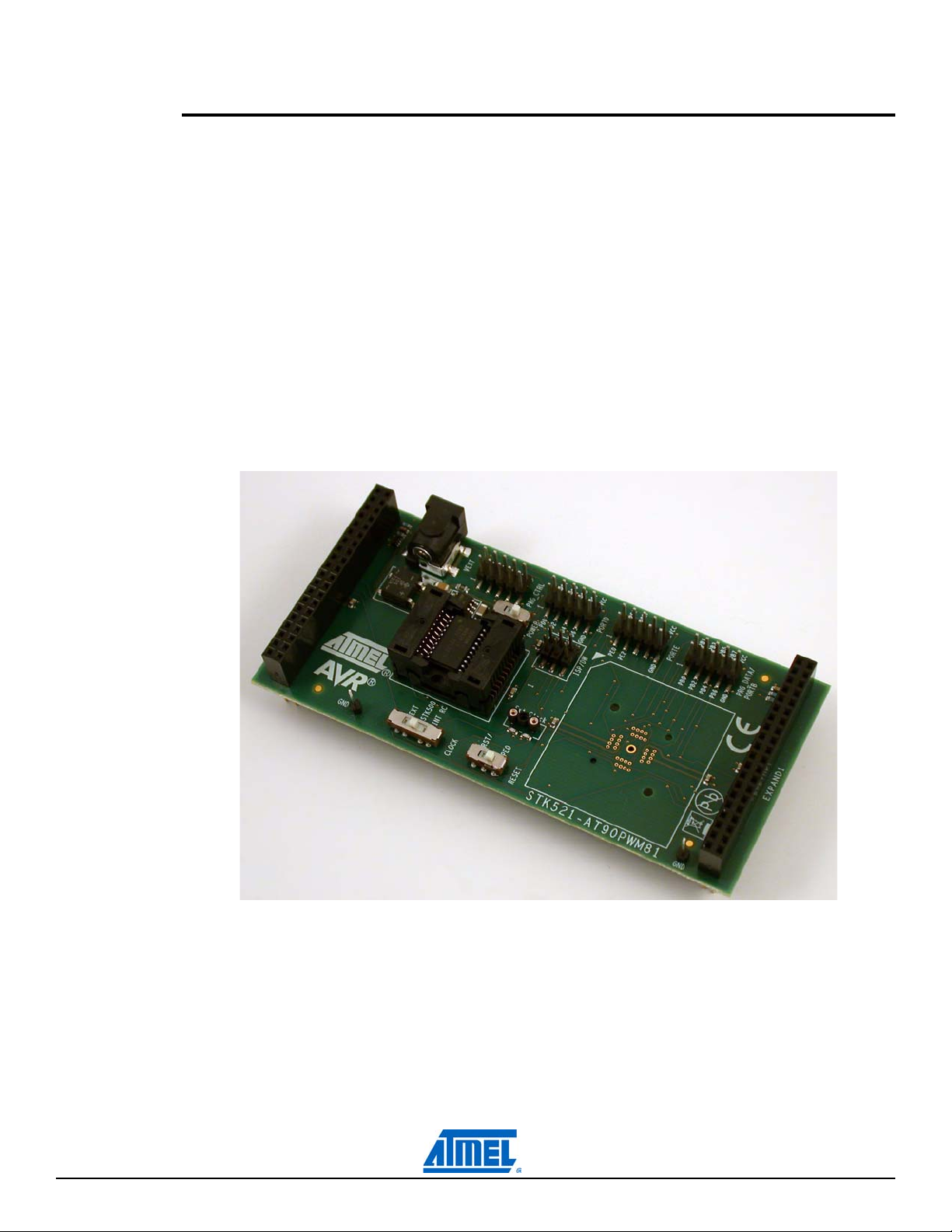
The Atmel® AVR® STK®521 kit is made of the Atmel AVR STK521 board.
The STK521 board is a top module for the Atmel STK500 development board from Atmel Corporation. It
is designed to support the Atmel AT90PWM81, Atmel AT90PWM161 products and future compatible
derivatives.
The STK521 includes connectors and hardware allowing full utilization of the new features of the
AT90PWM81/161, while the Zero Insertion Force (ZIF) socket allows easy to use of SOIC20 package for
prototyping.
This user guide acts as a general getting started guide as well as a complete technical reference for
advanced users.
Note that in this guide, the word AVR is used to refer to the target components (AT90PWM81/161).
AT90PWM81 will be also used to refer to one of the products from this family.
Figure 1-1. STK521 Top Module for STK500.
STK521 User Guide 1-1
8194B–AVR–01/12

1.1 Features
Atmel AVR STK521 is a new member of the successful Atmel STK500 starter kit family
Supports the Atmel AT90PWM81, Atmel AT90PWM161
Supported by Atmel AVR Studio
Zero Insertion Force Socket for SOIC20 Package
Zero Insertion Force Socket for QFN32 Package (not populated)
High Voltage Parallel Programming
Serial Programming
6-pin Connector for On-chip Debugging using Atmel AVR JTAGICE mkII or Atmel AVR Dragon
Switches for Reset/GPIOs configuration, Xtal/GPIOs or power supply configuration
External power supply connector for standalone mode
Quick Reference to all Jumpers in the Silk-Screen of the PCB
emulators
®
4.15 or above and Atmel AVR Studio 5.1
™
STK521 User Guide 1-2
8194B–AVR–01/12
Using the STK521 Top Module
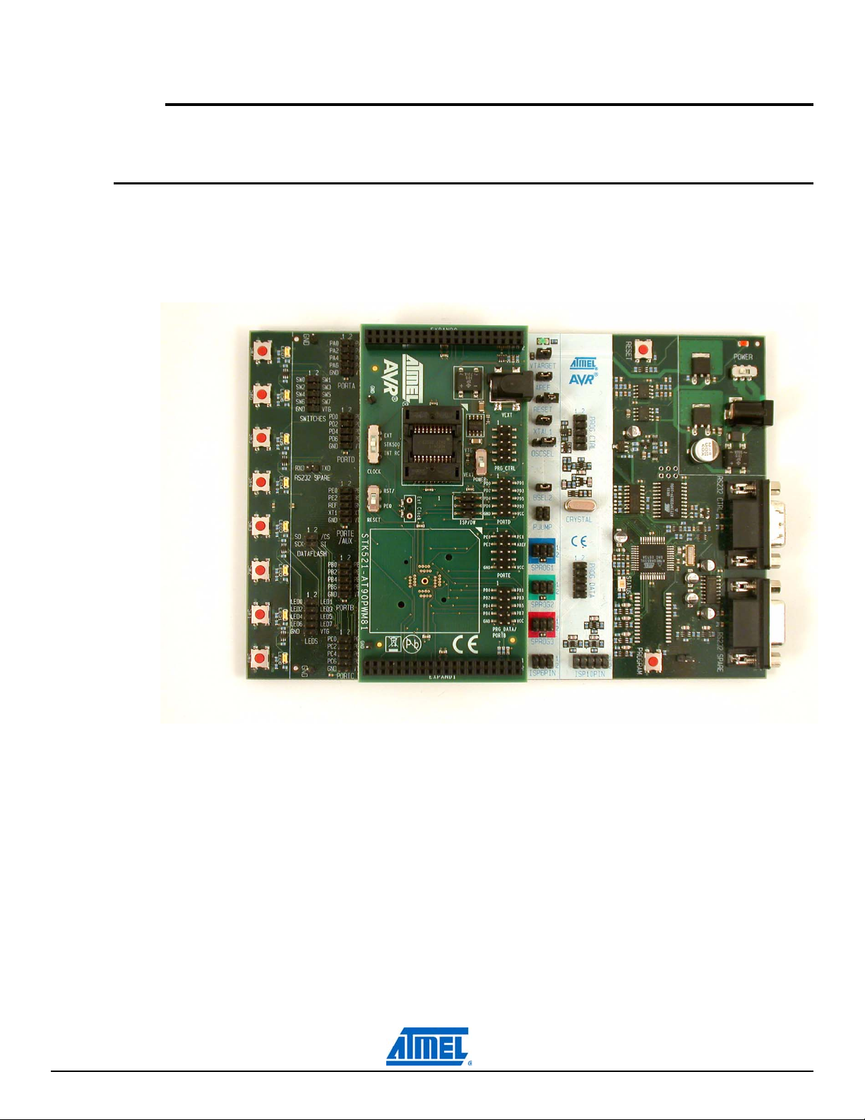
2.1 Connecting the Atmel STK521 to the Atmel STK500 Starter Kit
Connect the STK521 to the STK500 expansion header 0 and 1. It is important that the top module is connected in the correct orientation as shown in Figure 2-1. The EXPAND0 written on the STK521 top
module should match the EXPAND0 written beside the expansion header on the STK500 board.
Figure 2-1. Connecting STK521 to the STK500 Board.
Section 2
Note: Connecting the STK521 with wrong orientation may damage the board.
STK521 User Guide 2-3
8194B–AVR–01/12
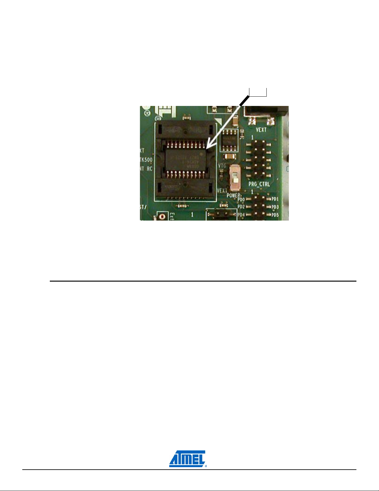
2.1.1 Placing an Atmel AT90PWM81 on the Atmel STK521
PIN1
The STK521 contains a ZIF socket for a SOIC20 package. Care should be taken so that the device is
mounted with the correct orientation. Figure 2-2 shows the location of pin1 for the ZIF socket.
Figure 2-2. Pin1 on ZIF Socket.
Caution: Do not mount an Atmel AT90PWM81 on the STK521 at the same time as an AVR is mounted
on the STK500 board. None of the devices might work as intended.
2.2 Powering the STK521
The STK521 can be powered as follows :
1. Through the STK500 by selecting POWER switch to VTG.
2. Through an external power supply using the jack connector and selecting POWER switch to
VEXT.
In this latter case, power supply must be 10V DC for a 5V device power supply.
STK521 User Guide 2-4
8194B–AVR–01/12
2.3 Programming the AVR
The Atmel AT90PWM81 can be programmed using both serial SPI and high-voltage parallel programming. This section will explain how to connect the programming cables to successfully use one of these
two modes. The Atmel AVR Studio STK500 software is used in the same way as for other AVR parts.
Note: The AT90PWM81 also supports Self Programming, see the Atmel AVR109 application note for
more information on this topic.
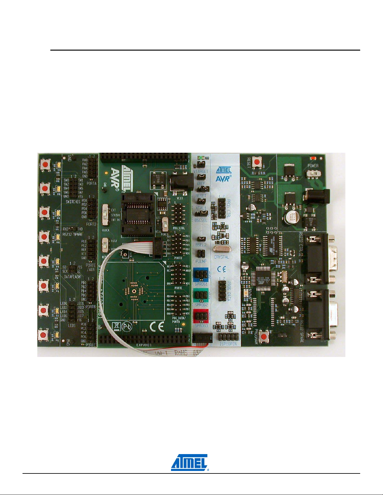
2.3.1 Serial in-system programming
Figure 2-3. Serial in-system programming.
To program the AT90PWM81 using ISP programming mode, connect the 6-wire cable between the
ISP6PIN connector on the Atmel STK500 board and the ISP connector on the Atmel STK521 board as
shown in Figure 2-3. The device can be programmed using the Serial Programming mode in the AVR
Studio 4 STK500 software.
STK521 User Guide 2-5
8194B–AVR–01/12
 Loading...