

Page 1

Table of Contents
TABLE OF CONTENTS
STK505 USER GUIDE .........................................................................................2
Introduction
Features
.........................................................................................................................2
..............................................................................................2
Getting Started
Hardware Overview
ZIF socket
DIP socket
Low voltage programming connectors
High voltage programming connectors
Port configuration switches
Crystal sockets
Mounting the STK505
...................................................................................................................................3
..................................................................................................................................3
.......................................................................................................................3
....................................................................1
..................................................................................3
.........................................................................................3
................................................................3
...............................................................3
..........................................................................................3
....................................................................................4
Clock Sources and Reset
The Clock Switch
The Reset/PORTB Switch .............................................................................................5
Programming the AVR
Introduction
In-System programming
High Voltage Programming
High Voltage Programming the ATtiny24
High Voltage Programming the ATtiny26..................................................................................8
.................................................................................................................6
................................................................................................5
........................................................6
.............................................................................6
....................................................................7
Troubleshooting Guide
Programming problems
General problems........................................................................................................11
.............................................................................10
..............................................5
.........................................................7
.....................................................10
1
Page 2
STK505 User Guide
Introduction
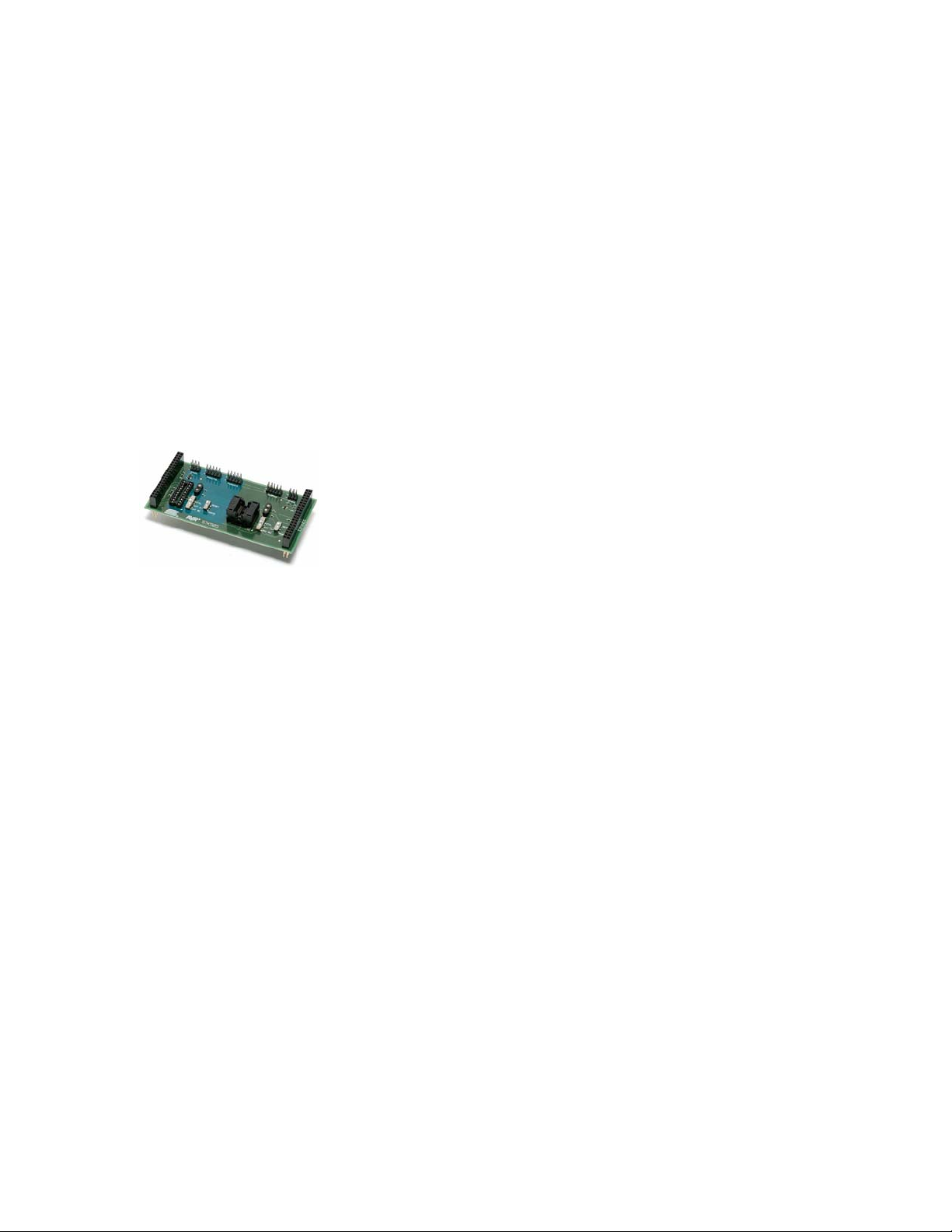
The STK505 board is a top module to the STK500 development board from
Atmel Corporation. It adds support for the 14-pin and 20-pin AVR
microcontrollers listed in the feature list below.
STK505 includes connectors and hardware allowing full utilization of the features
of these devices.
This user guide is a general getting started guide as well as a complete technical
reference for advanced users.
Included in the kit is samples of ATtiny24 and ATtiny26.
Figure 1-1: The STK505 starter kit
Features
• Supports the ATtiny24 and ATtiny26
• Supported by AVR Studio 4
• Zero Insertion Force (ZIF) socket for 14-pin SOIC packages
• DIP socket for 20-pin PDIP packages
• Supports High Voltage Programming through STK500
• Supports Low Voltage programming through STK500
• Switch to select between different clock sources
• Switch to select between reset and I/O functionality for the reset pin
• On board crystal sockets
2
Page 3

Getting Started
This section describes how to connect the STK505 onto the STK500, and
connect cables to different peripherals.
Hardware Overview
The STK505 is divided into two colored sections: the green section that supports
the ATtiny24 and the blue section that supports the ATtiny26.
Note: Only one AVR device should be inserted in the sockets at a time.
ZIF socket
The ZIF socket is for the ATtiny24, in soic package.
Pin1 on the socket is indicated with the white triangle beside the lower right
corner.
DIP socket
The DIP socket is for the ATtiny26.
Pin1 on the socket is indicated with the white triangle beside the lower right
corner.
Low voltage programming connectors
The AVR can be programmed in serial mode by using a 6-pin cable between the
ISP6PIN on the STK500 and the SPROG headers on the stk505.
High voltage programming connectors
The ATtiny26 can be programmed in parallel high voltage mode by using 10-pin
cables between STK500 and STK505.
The ATtiny24 can be programmed in serial high voltage mode be using 10-pin
cables between STK500 and STK505.
Port configuration switches
The XTAL1, XTAL2 and the reset pin on both ATtiny24 and ATtiny26 can also be
used as regular I/O port pins when not used as clock inputs or reset.
The pin configuration switches connects the pins to different components/signals
dependant on their usage.
This is described in more detail in the chapter Clock Sources and Reset
Crystal sockets
The clock crystal sockets are placed close to each target socket to make it
possible to use high frequency crystals.
When crystals are used to generate the target clock signal the clock selection
switch must be in position "XTAL".
3
Page 4

Mounting the STK505
The first thing you should do is to mount the STK505 onto the STK500.
1. Turn off the power on STK500.
2. Remove any other top card from the STK500.
3. Remove any AVR mounted in any of the sockets on the STK500.
4. Place the STK505 on top of the STK500. Make sure the EXPAND0 and
EXPAND1 connectors on both cards align properly.
4
Page 5

Clock Sources and Reset
The Clock Switch
The STK505 has support to easily configure the hardware to support three
different clock configurations
• External Clock
• On board crystal
• Internal Oscillator
The XTAL1 and XTAL2 pins are configured as regular I/O port pins when not
used as clock input/output.
The clock selection switch is used to connect the pins to different components
dependant on whether it is used as clock pins or I/O pins.
Note: The device fuses must be programmed to use the selected clock source.
See the device datasheet for more details.
Position Function
XTAL XTAL1 and XTAL2 pins connected to the XTAL
socket
EXT CLK XTAL1 pin connected to the STK500 clock source
XTAL2 pin connected to PORTB header
INT RC XTAL1 and XTAL2 pins connected to the PORTB
header
The Reset/PORTB Switch
The RESET/PORTB switch connects the reset pin to either the reset signal from
STK500, or to the PORTB header on STK500 to make it accessible for use as a
regular I/O pin.
Note: The RSTDISBL fuse must be programmed to disable reset functionality
and use the pin as a regular I/O port pin. Se the device datasheet for further
details.
5
Page 6

Programming the AVR
Introduction
There are two different ways of programming the AVR on STK505:
1. Low Voltage Programming (also called In-System Programming)
2. High-Voltage Programming (serial mode for tiny24 or parallel mode for
tiny26)
From now on Low Voltage Programming will be described as In-System
Programming.
The following sections will describe how to connect the appropriate cables. See
the STK500 user guide for how to use the AVR Studio Programming Dialog.
In-System programming
To program the device on the STK505 using the In-System Programming (ISP)
mode, connect a 6-pin cable between the ISP6PIN connector on STK500 and the
SPROG connector on STK505 colored section corresponding to the device used.
I.e. if programming ATtiny24, connect the 6-pin cable to the SPROG header on
the green section, as shown in figure 2-1.
If programming ATtiny26 connect the 6-pin cable to the SPROG header on the
blue section, as shown in figure 2-2.
Then start the Programming Dialog in AVR Studio
Figure 2-1: In-System Programming of the ATtiny24
6
Page 7

Figure 2-2: In-System Programming of the ATtiny26
Note: To be able to ISP program the AVR, the ISP programming enable fuse
must be set. The ISP programming enable fuse can be programmed by High-
Voltage Programming.
Please consult the Fuses section in the STK500 documentation.
High Voltage Programming
High-Voltage Programming requires the target voltage to be set to between 4.5
and 5.5V. If you have any external hardware connected to STK505/STK500 that
does not tolerate these levels, it must be disconnected before you High-Voltage
program the AVR.
High Voltage Programming the ATtiny24
To program the ATtiny24 mounted on STK505 using High-Voltage Programming,
follow these steps:
1. Turn off the STK500 power switch
2. Disconnect from STK500 and STK505 any hardware that does not tolerate
5V.
3. Connect the PROGDATA on STK500 to HVSPROG on STK505, as
shown on figure 2-3.
4. Connect the PROGCTRL on STK500 to the PORTA header on STK500,
as shown on figure 2-3.
5. Set jumpers and switches according to table 2-1.
6. Turn on STK500 power.
7. Start the Programming Dialog in AVR Studio
7
Page 8

Figure 2-3: High voltage programming of the ATtiny24
Table 2-1: High-Voltage programming jumper settings for ATtiny24
STK500
VTARGET Mounted
AREF Optional
RESET Mounted
XTAL1 Mounted
OSCSEL Mounted, pin 1
and 2
BSEL2 Mounted
PJUMP Open
STK505
RESET Switch RESET position
XTAL Switch EXT CLK
position
High Voltage Programming the ATtiny26
To program the ATtiny26 mounted on STK505 using High-Voltage Programming,
follow these steps:
1. Turn off the STK500 power switch.
2. Disconnect from STK500 and STK505 any hardware that does not tolerate
5V.
3. Connect PROGCTRL on stk500 to PROGCTRL on STK505, as shown on
figure 2-4.
4. Connect PROGDATA on stk500 to PROGDATA on STK505, as shown on
figure 2-4.
5. Set jumpers and switches according to table 2-2.
6. Turn on STK500 power.
7. Start the Programming Dialog in AVR Studio
8
Page 9

Figure 2-4: High voltage programming of the ATtiny26
Table 2-2: High-Voltage programming jumper settings for the ATtiny26
STK500
VTARGET Mounted
AREF Optional
RESET Mounted
XTAL1 Mounted
OSCSEL Mounted, pin 1
and 2
BSEL2 Not Mounted
PJUMP Open
STK505
RESET Switch RESET position
XTAL Switch EXT CLK
position
9
Page 10

Troubleshooting Guide
Programming problems
Problem
ISP
programming
does not work
ISP
programming
does not work
ISP
programming
does not work
ISP
programming
does not work
ISP
programming
does not work
High-Voltage
programming
does not work.
High-Voltage
programming
does not work.
High-Voltage
programming
does not work.
High-Voltage
programming
does not work.
Cause
ISP cable is not
connected
The AVR is running at
too low clock
frequency.
The SPI enable fuse is
not programmed.
The Reset Disable fuse
is programmed.
The DebugWire fuse is
programmed.
The 10-pin cables are
not connected
correctly.
The (BSEL2),
OSCSEL, RESET and
VTARGET jumpers on
STK500 are not set
correctly.
The STK505 clock
switch is in the wrong
position.
The STK505 Reset
switch is in PORTB
position
Solution
Connect a 6-pin cable between the
ISP6PIN connector on STK500 and
the ISP connector on STK505 on the
selected target section. See also
Programming the AVR.
Make sure the clock switch on
STK500 is in the right position. In
the Board page of the programming
dialog in AVR Studio, try reducing
the clock frequency so less or equal
to the frequency the AVR is running
at.
Program the SPI enable fuse using
high voltage programming.
Unprogram the Reset Disable fuse
using high voltage programming.
Unprogram the DebugWire fuse using
high voltage programming.
See the Programming the AVR
chapter for setup.
See the Programming the AVR
chapter for setup.
Set the switch to the EXT CLK
position. See also Programming the
AVR.
Set the switch to the RESET position.
10
Page 11

General problems
Problem
Some of the
port pins are
not working.
Cause
The AVR is not
properly mounted in
the ZIF socket.
Solution
Make sure the chip is properly
aligned in the socket. When the
spring-loaded latch is depressed,
the chip should fit nicely into the
The code isn't
running.
The AVR has
no/wrong clock
source.
bottom of the socket.
According to the clock fuse setting,
select the appropriate clock source
on STK500 and STK505. Check the
OSCSEL jumper on STK500 and
clock switch on STK505. If you are
using a crystal in one of the
sockets, check that it is firmly
The AVR will
not run on x
MHz, but works
ok on lower
frequencies.
The AVR will
not run on x
MHz, but works
The clock frequency is
exceeding the clock
rate of the AVR (at a
certain operating
voltage).
Crystals should be
placed in the crystal
socket on STK505.
mounted in its socket.
Check that you are running the AVR
within specifications. Check the speed
grade of the AVR and consult the
datasheet for operating frequencies
and voltages.
Place the crystal in the socket on
STK505. Set the clock switch to the
HF position.
ok on lower
frequencies. I
have a x MHz
crystal
mounted on
STK500
Disclaimer: The information in this document is provided in connection with Atmel products. No license, express or implied, by estoppel or
otherwise, to any intellectual property right is granted by this document or in connection with the sale of Atmel products. EXCEPT AS SET
FORTH IN ATMEL’S TERMS AND CONDITIONS OF SALE LOCATED ON ATMEL’S WEB SITE, ATMEL ASSUMES NO LIABILITY
WHATSOEVER AND DISCLAIMS ANY EXPRESS, IMPLIED OR STATUTORY WARRANTY RELATING TO ITS PRODUCTS
INCLUDING, BUT NOT LIMITED TO, THE IMPLIED WARRANTY OF MERCHANTABILITY, FITNESS FOR A PARTICULAR PURPOSE,
OR NON-INFRINGEMENT. IN NO EVENT SHALL ATMEL BE LIABLE FOR ANY DIRECT, INDIRECT, CONSEQUENTIAL, PUNITIVE,
SPECIAL OR INCIDENTAL DAMAGES (INCLUDING, WITHOUT LIMITATION, DAMAGES FOR LOSS OF PROFITS, BUSINESS
INTERRUPTION, OR LOSS OF INFORMATION) ARISING OUT OF THE USE OR INABILITY TO USE THIS DOCUMENT, EVEN IF
ATMEL HAS BEEN ADVISED OF THE POSSIBILITY OF SUCH DAMAGES. Atmel makes no representations or warranties with respect
to the accuracy or completeness of the contents of this document and reserves the right to make changes to specifications and product
descriptions at any time without notice. Atmel does not make any commitment to update the information contained herein. Unless
specifically provided otherwise, Atmel products are not suitable for, and shall not be used in, automotive applications. Atmel’s products are
not intended, authorized, or warranted for use as components in applications intended to support or sustain life.
© Atmel Corporation 2005. All rights reserved. Atmel®, logo and combinations thereof, Everywhere You Are®,
AVR®, AVR Studio® and others, are the registered trademarks or trademarks of Atmel Corporation or its
subsidiaries. Other terms and product names may be trademarks of others.
11
 Loading...