

Page 1

SpW-10X
SpaceWire Router
User Manual
Ref.:
Issue:
Date:
UoD_SpW-10X_
UserManual
3.4
th
July 2008
11
SpW-10X SpaceWire Router
User Manual
Ref: UoD_SpW-10X_UserManual
Atmel Part No.: AT7910E
Document Revision: Issue 3.4
Date: 11th July 2008
Prepared by - Chris McClements, University of Dundee
Steve Parkes, University of Dundee
Gerald Kempf, Austrian Aerospace
Checked by - Steve Parkes, University of Dundee
ESA Manager - Pierre Fabry, ESTEC
Preliminary
1
Page 2

SpW-10X
SpaceWire Router
User Manual
Ref.:
Issue:
Date:
UoD_SpW-10X_
UserManual
3.4
th
July 2008
11
Document Change log
Date Issue Comments Author
19th-March-2004 Issue 1.0 Initial draft version Chris McClements
26th-August-2004 Issue 1.2 Timing for FPGA model added Chris McClements
16 November 2004 Issue 1.3 Register Definitions Updated Chris McClements
27 April 2004 Issue 1.4 Latency and Jitter Specifications
added
2 May 2005 Issue 1.5 Footer indicates “Preliminary.”
Section 8.6 subject to change
notice added to front page.
21 December 2005 Issue 1.6 RMAP section added Chris McClements
19th July 2006 Issue 1.7 Corrections and clarifications Chris McClements
18th August 2006 Issue 2.0 Editorial changes and
clarifications
3rd July 2007 Issue 2.1 Added sections on ASIC pin
placement, ASIC power
consumption, bias resistors,
phase locked loop and
anomalies.
28th September 2007 Issue 2.2 Modifications before handed to
Atmel
Chris McClements
Steve Parkes
Steve Parkes
Chris McClements
Steve Parkes
Chris McClements,
Gerald Kempf
4th October 2007 Issue 2.3 Modifications to SpaceWire
signal names (Map pin 1 to 0)
3rd December 2007 Issue 2.4 Updates as user manual.
Changed document name to
UoD_SpW_10X_UserManual.doc
11th December 2007 Issue 2.5 Redistribute with PLL settings Chris McClements
18th January 2008 Issue 3.0 Major edit providing clarifications
and additional application details
throughout document.
Section added on Application
Guidelines giving example circuit
diagram and PCB layout
Preliminary
Chris McClements,
Gerald Kempf
Chris McClements,
Gerald Kempf
Gerald Kempf
Steve Parkes
2
Page 3

SpW-10X
SpaceWire Router
User Manual
guidelines.
Section added on anomalies and
warnings.
Section added on Technical
Support.
Ref.:
Issue:
Date:
UoD_SpW-10X_
UserManual
3.4
th
July 2008
11
20th January 2008 Issue 3.1 Corrections and example
schematic improved.
18th April 2008 Issue 3.2 Explanation of non-blocking
cross bar switch added.
Cold sparing information added.
VCO bias resistor value
corrected (Section 5.7.4).
Tri-state mode changed to
deactivate mode.
Description for ‘time-code flag
mode bit’ added.
Reliability information added.
Anomaly 2 resolved.
Details and workarounds for
reset anomaly provided.
30th April 2008 Issue 3.3 RD 3 changed.
Steve Parkes
Steve Parkes
Steve Parkes
Editorial corrections.
Correction to reset value of GAR
table entry.
Correction to support email
address.
11th July Issue 3.4 Data after parity error anomaly
added.
Detailed timing information
added.
DC characteristics updated.
Preliminary
Steve Parkes
Gerald Kempf
3
Page 4

SpW-10X
SpaceWire Router
User Manual
Ref.:
Issue:
Date:
UoD_SpW-10X_
UserManual
3.4
th
July 2008
11
CONTENTS
CONTENTS..............................................................................................................................................4
I LIST OF FIGURES .......................................................................................................................... 10
II LIST OF TABLES........................................................................................................................... 12
1. INTRODUCTION............................................................................................................................ 14
1.1 TERMS, ACRONYMS AND ABBREVIATIONS ........................................................................... 14
1.2 DOCUMENTS .............................................................................................................................. 15
2. USER APPLICATIONS ................................................................................................................. 16
2.1 STAND-ALONE ROUTER ........................................................................................................... 16
2.2 NODE INTERFACE ..................................................................................................................... 17
2.3 EMBEDDED ROUTER.................................................................................................................17
2.4 EXPANDING THE NUMBER OF ROUTER PORTS ................................................................... 18
3. FUNCTIONAL OVERVIEW ........................................................................................................... 21
3.1 SPACEWIRE PORTS .................................................................................................................. 22
3.2 EXTERNAL PORTS..................................................................................................................... 22
3.3 CONFIGURATION PORT............................................................................................................ 23
3.4 ROUTING TABLE ........................................................................................................................ 23
3.5 ROUTING CONTROL LOGIC AND CROSSBAR........................................................................ 23
3.6 TIME-CODE PROCESSING ........................................................................................................ 24
3.7 CONTROL/STATUS REGISTERS .............................................................................................. 24
4. PIN LOCATIONS........................................................................................................................... 25
5. DEVICE INTERFACE.................................................................................................................... 31
5.1 GLOBAL SIGNALS ...................................................................................................................... 31
5.2 SPACEWIRE SIGNALS...............................................................................................................32
5.2.1 SpW-10X SpaceWire Signals ................................................................................................... 32
5.2.2 SpaceWire Input Fail Safe Resistors ........................................................................................ 35
5.2.3 Operation with 5V Powered LVDS Devices.............................................................................. 37
Preliminary
4
Page 5

SpW-10X
5.3 EXTERNAL PORT DATA SIGNALS............................................................................................ 37
5.4 TIME-CODE SIGNALS ................................................................................................................ 39
5.5 STATUS INTERFACE SIGNALS................................................................................................. 41
5.6 RESET CONFIGURATION SIGNALS ......................................................................................... 42
5.7 POWER, GROUND, PLL AND LVDS SIGNALS ......................................................................... 45
5.7.1 General...................................................................................................................................... 45
5.7.2 Decoupling ................................................................................................................................ 45
5.7.3 LVDS Reference ....................................................................................................................... 45
5.7.4 PLL External Components ........................................................................................................ 45
6. INTERFACE OPERATIONS.......................................................................................................... 47
SpaceWire Router
User Manual
Ref.:
Issue:
Date:
UoD_SpW-10X_
UserManual
3.4
th
July 2008
11
6.1 EXTERNAL PORT INTERFACE OPERATION ........................................................................... 47
6.2 TIME-CODE INTERFACE OPERATION ..................................................................................... 48
6.3 STATUS INTERFACE OPERATION ........................................................................................... 49
6.4 RESET CONFIGURATION INTERFACE OPERATION .............................................................. 51
7. SPACEWIRE ROUTER PACKET TYPES .................................................................................... 52
7.1 PACKET ADDRESSES................................................................................................................52
7.2 PACKET PRIORITY..................................................................................................................... 53
7.3 PACKET HEADER DELETION.................................................................................................... 53
7.4 INVALID ADDRESSES ................................................................................................................ 54
7.5 DATA PACKETS.......................................................................................................................... 55
7.6 COMMAND PACKETS ................................................................................................................ 55
7.6.1 Supported Commands ..............................................................................................................55
7.6.2 Read Command ........................................................................................................................ 56
7.6.3 Read Incrementing Command .................................................................................................. 60
7.6.4 Read Modify Write Command................................................................................................... 65
7.6.5 Write Command ........................................................................................................................ 70
7.6.6 Command Error Response ....................................................................................................... 74
7.6.7 Command Packet Cyclic Redundancy Check .......................................................................... 76
7.6.8 Local Source Path Address ...................................................................................................... 76
7.6.9 Source Path Address Field .......................................................................................................77
7.6.10 Command Packet Fill Bytes.................................................................................................... 78
8. CONTROL LOGIC AND OPERATIONAL MODES....................................................................... 79
8.1 SPACEWIRE LINK CONTROL.................................................................................................... 79
8.1.1 Default operating mode............................................................................................................. 79
Preliminary
5
Page 6

SpW-10X
8.1.2 Auto-Start .................................................................................................................................. 79
8.1.3 Link-Start................................................................................................................................... 79
8.1.4 Link-Disable .............................................................................................................................. 80
8.1.5 Automatic deactivate driver mode............................................................................................. 80
8.1.6 Setting the SpaceWire port transmit data rate.......................................................................... 82
8.2 GLOBAL SPACEWIRE LINK CONTROL .................................................................................... 84
8.2.1 Start on request mode............................................................................................................... 85
8.2.2 Disable on Silence mode .......................................................................................................... 85
8.3 CONTROL LOGIC AND ROUTING ............................................................................................. 86
8.3.1 Packet address error................................................................................................................. 86
8.3.2 Arbitration.................................................................................................................................. 86
8.3.2.1 Arbitration of packets with matching priority (1)..................................................................... 87
8.3.2.2 Arbitration of packets with matching priority (2)..................................................................... 88
8.3.2.3 Arbitration of packets with different priority (1) ...................................................................... 89
8.3.2.4 Arbitration of packets with different priority (2) ...................................................................... 90
8.3.3 Group Adaptive Routing............................................................................................................ 92
8.3.3.1 Normal Group adaptive routing.............................................................................................. 92
8.3.3.2 Group adaptive routing when busy ........................................................................................ 92
8.3.3.3 Group adaptive routing when ports not ready........................................................................ 93
8.3.4 Loop-back with Self-Addressing ............................................................................................... 93
8.3.5 Packet Blocking......................................................................................................................... 95
8.3.5.1 Blocked destination ................................................................................................................ 95
8.3.5.2 Stalled source ........................................................................................................................ 98
8.3.5.3 Waiting for an output port..................................................................................................... 101
SpaceWire Router
User Manual
Ref.:
Issue:
Date:
UoD_SpW-10X_
UserManual
3.4
th
July 2008
11
9. REGISTER DEFINITIONS........................................................................................................... 103
9.1 INTERNAL MEMORY MAP ....................................................................................................... 103
9.2 REGISTER ADDRESSES SUMMARY ...................................................................................... 104
9.3 GROUP ADAPTIVE ROUTING TABLE REGISTERS ............................................................... 105
9.4 PORT CONTROL/STATUS REGISTERS ................................................................................. 108
9.4.1 Generic port control/status register fields. .............................................................................. 108
9.4.2 Configuration port control/status register fields. ..................................................................... 109
9.4.3 SpaceWire port control/status register bits. ............................................................................ 112
9.4.4 External port control/status register bits.................................................................................. 115
9.5 ROUTER CONTROL/STATUS REGISTERS ............................................................................ 115
9.5.1 Network Discovery Register.................................................................................................... 115
9.5.2 Router Identity Register .......................................................................................................... 116
9.5.3 Router Control Register .......................................................................................................... 117
9.5.4 Error active Register ............................................................................................................... 120
Preliminary
6
Page 7

SpW-10X
9.5.5 Time-Code Register ................................................................................................................ 121
9.5.6 Device Manufacturer and Chip ID Register ............................................................................ 122
9.5.7 General Purpose Register....................................................................................................... 123
9.5.8 Time-Code Enable Register.................................................................................................... 123
9.5.9 Transmit Clock Control Register ............................................................................................. 124
9.5.10 Destination Key Register....................................................................................................... 127
9.5.11 Unused Registers and Register Bits..................................................................................... 127
9.5.12 Empty packets....................................................................................................................... 127
9.6 WRITING TO A READ-ONLY REGISTER................................................................................. 127
10. SWITCHING CHARACTERISTICS........................................................................................... 128
10.1 CLOCK AND RESET TIMING PARAMETERS........................................................................ 128
SpaceWire Router
User Manual
Ref.:
Issue:
Date:
UoD_SpW-10X_
UserManual
3.4
th
July 2008
11
10.2 SERIAL SIGNALS TIMING PARAMETERS ............................................................................ 128
10.3 EXTERNAL PORT TIMING PARAMETERS............................................................................ 129
10.4 TIME-CODE INTERFACE TIMING PARAMETERS................................................................ 130
10.5 ERROR/STATUS INTERFACE TIMING PARAMETERS........................................................ 131
10.6 LATENCY AND JITTER........................................................................................................... 133
10.6.1 Clock Periods ........................................................................................................................ 133
10.6.2 Switching Latency ................................................................................................................. 133
10.6.3 Router Latency...................................................................................................................... 133
10.6.4 Time-code Latency................................................................................................................ 134
10.6.5 Time-code Jitter .................................................................................................................... 135
10.6.6 200M bits/s Input and Output Bit Rate Example................................................................... 135
11. ELECTRICAL CHARACTERISTICS......................................................................................... 136
11.1 DC CHARACTERISTICS......................................................................................................... 136
11.2 ABSOLUTE MAXIMUM RATINGS .......................................................................................... 137
11.3 RELIABILITY INFORMATION.................................................................................................. 137
12. APPLICATION GUIDELINES.................................................................................................... 138
12.1 EXAMPLE CIRCUIT DIAGRAM............................................................................................... 138
12.2 PCB DESIGN AND LAYOUT GUIDELINES............................................................................ 140
12.2.1 CLK ....................................................................................................................................... 140
12.2.2 RST_N................................................................................................................................... 140
12.2.3 Chip Test Signals .................................................................................................................. 140
12.2.4 Power and Decoupling.......................................................................................................... 140
12.2.5 Ground .................................................................................................................................. 140
12.2.6 SpaceWire............................................................................................................................. 140
Preliminary
7
Page 8

SpW-10X
12.2.7 External Ports........................................................................................................................ 141
12.2.8 Time-code Interface .............................................................................................................. 141
12.2.9 Status / Power On Configuration Interface ........................................................................... 141
12.2.10 PLL...................................................................................................................................... 142
13. ANOMALIES AND WARNINGS................................................................................................ 143
13.1 ANOMALIES ............................................................................................................................ 143
13.2 WARNINGS ............................................................................................................................. 143
13.3 RESET ANOMALY................................................................................................................... 145
13.3.1 Data Strobe Reset Waveform ............................................................................................... 145
13.3.2 Data Strobe Disable Waveform ............................................................................................ 147
13.3.3 Reset Anomaly Workarounds ............................................................................................... 147
SpaceWire Router
User Manual
Ref.:
Issue:
Date:
UoD_SpW-10X_
UserManual
3.4
th
July 2008
11
13.4 PARITY ERROR ANOMALY.................................................................................................... 148
13.4.1 Parity Error Action ................................................................................................................. 148
13.4.2 Parity Error Anomaly............................................................................................................. 148
13.4.3 Parity Error Workaround ....................................................................................................... 149
14. TECHNICAL SUPPORT............................................................................................................ 150
15. DOCUMENT CHANGES ........................................................................................................... 151
15.1 ISSUE 3.3 TO ISSUE 3.4......................................................................................................... 151
15.2 ISSUE 3.2 TO ISSUE 3.3......................................................................................................... 151
15.3 ISSUE 3.1 TO ISSUE 3.2......................................................................................................... 151
15.4 ISSUE 3.0 TO ISSUE 3.1......................................................................................................... 152
15.5 ISSUE 2.5 TO ISSUE 3.0......................................................................................................... 152
15.6 ISSUE 2.4 TO ISSUE 2.5......................................................................................................... 153
15.7 ISSUE 2.3 TO ISSUE 2.4......................................................................................................... 153
15.8 ISSUE 2.2 TO ISSUE 2.3......................................................................................................... 153
15.9 ISSUE 2.1 TO ISSUE 2.2......................................................................................................... 154
15.10 ISSUE 2.0 TO ISSUE 2.1....................................................................................................... 154
15.11 ISSUE 1.7 TO ISSUE 2.0....................................................................................................... 154
15.12 ISSUE 1.6 TO ISSUE 1.7....................................................................................................... 154
15.13 ISSUE 1.5 TO ISSUE 1.6....................................................................................................... 154
15.14 ISSUE 1.4 TO ISSUE 1.5....................................................................................................... 154
15.15 ISSUE 1.3 TO ISSUE 1.4....................................................................................................... 154
Preliminary
8
Page 9

SpW-10X
15.16 ISSUE 1.2 TO ISSUE 1.3....................................................................................................... 154
15.17 ISSUE 1.1 TO ISSUE 1.2....................................................................................................... 155
15.18 ISSUE 1.0 TO ISSUE 1.1....................................................................................................... 155
SpaceWire Router
User Manual
Ref.:
Issue:
Date:
UoD_SpW-10X_
UserManual
3.4
th
July 2008
11
Preliminary
9
Page 10

SpW-10X
SpaceWire Router
User Manual
Ref.:
Issue:
Date:
UoD_SpW-10X_
UserManual
3.4
th
July 2008
11
I LIST OF FIGURES
FIGURE 2-1 STAND-ALONE ROUTER...................................................................................................................... 16
FIGURE 2-2 NODE INTERFACE................................................................................................................................17
FIGURE 2-3 EMBEDDED ROUTER ........................................................................................................................... 18
FIGURE 2-4 EXPANDING THE NUMBER OF SPACEWIRE PORTS (1).......................................................................... 19
FIGURE 2-5 EXPANDING THE NUMBER OF SPACEWIRE PORTS (2).......................................................................... 20
FIGURE 3-1 SPACEWIRE ROUTER BLOCK DIAGRAM ............................................................................................... 22
FIGURE 5-1 LVDS RECEIVER FAIL-SAFE RESISTORS ............................................................................................ 35
FIGURE 5-2 CONFIGURATION INTERFACE TIMING SPECIFICATION .......................................................................... 42
FIGURE 5-3 PLL WITH EXTERNAL COMPONENTS.................................................................................................... 46
FIGURE 6-1 EXTERNAL PORT WRITE TIMING SPECIFICATION .................................................................................. 47
FIGURE 6-2 EXTERNAL PORT READ TIMING SPECIFICATION.................................................................................... 48
FIGURE 6-3 TIME-CODE INPUT INTERFACE............................................................................................................ 48
FIGURE 6-4 TIME-CODE OUTPUT INTERFACE ........................................................................................................ 49
FIGURE 6-5 TIME-CODE RESET INTERFACE............................................................................................................. 49
FIGURE 6-6 STATUS MULTIPLEXER OUTPUT INTERFACE ........................................................................................ 49
FIGURE 6-7 RESET CONFIGURATION INTERFACE TIMING SPECIFICATION................................................................ 51
FIGURE 7-1 NORMAL ROUTER DATA PACKETS ....................................................................................................... 55
FIGURE 7-2 COMMAND PACKET FORMAT .............................................................................................................. 55
FIGURE 7-3 READ SINGLE ADDRESS COMMAND FORMAT ..................................................................................... 57
FIGURE 7-4 READ SINGLE ADDRESS REPLY PACKET FORMAT............................................................................... 59
FIGURE 7-5 READ INCREMENTING ADDRESS COMMAND FORMAT......................................................................... 62
FIGURE 7-6 READ INCREMENTING ADDRESS REPLY PACKET FORMAT .................................................................. 64
FIGURE 7-7 READ-MODIFY-WRITE COMMAND PACKET FORMAT ......................................................................... 66
FIGURE 7-8 READ-MODIFY-WRITE EXAMPLE OPERATION ..................................................................................... 68
FIGURE 7-9 READ-MODIFY-WRITE REPLY PACKET FORMAT ................................................................................ 69
FIGURE 7-10 WRITE SINGLE ADDRESS COMMAND PACKET................................................................................... 71
FIGURE 7-11 WRITE SINGLE ADDRESS REPLY PACKET ......................................................................................... 73
FIGURE 7-12 SOURCE PATH ADDRESS FIELD DECODING ........................................................................................ 78
FIGURE 7-13 SOURCE PATH ADDRESSES IN REPLY PACKET .................................................................................. 78
FIGURE 7-14 NORMAL CONFIGURATION PACKET HEADER STRUCTURE ................................................................ 78
FIGURE 7-15 FILL BYTES CONFIGURATION HEADER STRUCTURE.......................................................................... 78
FIGURE 8-1 DEACTIVATE DRIVER OPERATING MODE ............................................................................................. 81
FIGURE 8-2 DEACTIVATED LDVS DRIVER OUTPUT................................................................................................ 81
FIGURE 8-3 DEACTIVATED LDVS DRIVER OUTPUT CONNECTED TO EXTERNAL BIAS NETWORK ON LVDS INPUT.. 82
FIGURE 8-4 START ON REQUEST MODE .................................................................................................................. 85
FIGURE 8-5 DISABLE ON SILENCE MODE................................................................................................................ 86
FIGURE 8-6 ARBITRATION OF TWO PACKETS WITH MATCHING PRIORITY. .............................................................. 87
FIGURE 8-7 ARBITRATION OF THREE PACKETS WITH MATCHING PRIORITY ............................................................ 88
Preliminary
10
Page 11

SpW-10X
FIGURE 8-8 ARBITRATION OF TWO PACKETS WITH DIFFERENT PRIORITY (1).......................................................... 89
FIGURE 8-9 ARBITRATION OF TWO PACKETS WITH DIFFERENT PRIORITY (2).......................................................... 91
FIGURE 8-10 NORMAL GROUP ADAPTIVE ROUTING ................................................................................................ 92
FIGURE 8-11 GROUP ADAPTIVE ROUTING WHEN OTHER PORTS BUSY..................................................................... 93
FIGURE 8-12 GROUP ADAPTIVE ROUTING WHEN PORTS NOT READY ...................................................................... 93
FIGURE 8-13 PACKET SELF-ADDRESSING MODE .................................................................................................... 94
FIGURE 8-14 DESTINATION NODE BLOCKED (A).................................................................................................... 96
FIGURE 8-15 DESTINATION NODE BLOCKED (B).................................................................................................... 96
FIGURE 8-16 DESTINATION NODE BLOCKED (C).................................................................................................... 97
FIGURE 8-17 DESTINATION NODE BLOCKED: WATCHDOG MODE (A).................................................................... 97
FIGURE 8-18 DESTINATION NODE BLOCKED: WATCHDOG MODE (B).................................................................... 97
FIGURE 8-19 DESTINATION NODE BLOCKED: WATCHDOG MODE (C).................................................................... 98
FIGURE 8-20 DESTINATION NODE BLOCKED: WATCHDOG MODE (D).................................................................... 98
FIGURE 8-21 SOURCE NODE STALLED (A) ............................................................................................................. 99
FIGURE 8-22 SOURCE NODE STALLED (B).............................................................................................................. 99
FIGURE 8-23 SOURCE NODE STALLED (C).............................................................................................................. 99
FIGURE 8-24 SOURCE NODE STALLED (D) ............................................................................................................. 99
FIGURE 8-25 SOURCE NODE STALLED: WATCHDOG MODE (A) ........................................................................... 100
FIGURE 8-26 SOURCE NODE STALLED: WATCHDOG MODE (B)............................................................................ 100
FIGURE 8-27 SOURCE NODE STALLED: WATCHDOG MODE (C)............................................................................ 100
FIGURE 8-28 SOURCE NODE STALLED: WATCHDOG MODE (D) ........................................................................... 100
FIGURE 9-1 ROUTER INTERNAL MEMORY MAP................................................................................................... 103
FIGURE 9-2 GAR REGISTER FIELDS..................................................................................................................... 105
FIGURE 9-3 SPACEWIRE PORT CONTROL/STATUS REGISTER FIELDS................................................................... 112
FIGURE 9-4 NETWORK DISCOVERY REGISTER FIELDS ......................................................................................... 116
FIGURE 9-5 ROUTER CONTROL REGISTER FIELDS................................................................................................ 117
FIGURE 9-6 ERROR ACTIVE REGISTER FIELDS ..................................................................................................... 120
FIGURE 9-7 TIME-CODE REGISTER FIELDS .......................................................................................................... 121
FIGURE 9-8 DEVICE MANUFACTURER AND CHIP ID REGISTER FIELDS................................................................ 122
FIGURE 9-9 TIME-CODE ENABLE REGISTER FIELDS............................................................................................. 123
FIGURE 9-10 TRANSMIT CLOCK CONTROL REGISTER........................................................................................... 125
FIGURE 10-1 DS MINIMUM CONSECUTIVE EDGE SEPARATION.............................................................................. 128
FIGURE 10-2 EXTERNAL PORT INPUT FIFO TIMING PARAMETERS........................................................................ 129
FIGURE 10-3 EXTERNAL PORT OUTPUT FIFO TIMING PARAMETERS..................................................................... 129
FIGURE 10-4 TIME-CODE INPUT INTERFACE ........................................................................................................ 130
FIGURE 10-5 TIME-CODE OUTPUT INTERFACE .................................................................................................... 131
FIGURE 10-6 TIME-CODE TIME_CTR_RST INTERFACE...................................................................................... 131
FIGURE 12-1 PLL LAYOUT RECOMMENDATIONS................................................................................................. 142
FIGURE 13-1 RESET WAVEFORM ......................................................................................................................... 146
FIGURE 13-2 RESET WAVEFORM WITH DATA AND STROBE BOTH HIGH.............................................................. 146
FIGURE 13-3 GLITCHES ON DATA OR STROBE DURING RESET ............................................................................. 146
FIGURE 13-4 SIMULTANEOUS TRANSITION OF DATA AND STROBE DURING RESET .............................................. 146
SpaceWire Router
User Manual
Ref.:
Issue:
Date:
UoD_SpW-10X_
UserManual
3.4
th
July 2008
11
Preliminary
11
Page 12

SpW-10X
FIGURE 13-5 LINK DISCONNECT WAVEFORMS .................................................................................................... 147
FIGURE 13-6 DATA AFTER PARITY ERROR ANOMALY........................................................................................... 148
FIGURE 13-7 NO ERROR END OF PACKET INSERTED AFTER PARITY ERROR ........................................................... 149
SpaceWire Router
User Manual
Ref.:
Issue:
Date:
UoD_SpW-10X_
UserManual
3.4
th
July 2008
11
II LIST OF TABLES
TABLE 1-1 APPLICABLE DOCUMENTS.................................................................................................................... 15
TABLE 1-2 REFERENCE DOCUMENTS..................................................................................................................... 15
TABLE 5-1 GLOBAL SIGNALS................................................................................................................................. 32
TABLE 5-2 DATA AND STROBE SPACEWIRE SIGNALS............................................................................................ 33
TABLE 5-3 EXTERNAL PORT INTERFACE SIGNALS................................................................................................. 37
TABLE 5-4 TIME-CODE SIGNALS ........................................................................................................................... 39
TABLE 5-5 LINK ERROR INDICATION SIGNALS ....................................................................................................... 41
TABLE 5-6 RESET CONFIGURATION SIGNALS......................................................................................................... 43
TABLE 5-7 POWER, GROUND AND SPECIAL SIGNALS............................................................................................. 45
TABLE 6-1 MULTIPLEXED STATUS PINS BIT ASSIGNMENT .................................................................................... 50
TABLE 7-1 PACKET ADDRESS MAPPING ................................................................................................................ 52
TABLE 7-2 PACKET PRIORITY MAPPING ................................................................................................................ 53
TABLE 7-3 PACKET HEADER DELETION MAPPING................................................................................................. 54
TABLE 7-4 SUPPORTED RMAP COMMAND CODES ................................................................................................ 56
TABLE 7-5 READ SINGLE ADDRESS CHARACTERISTICS ......................................................................................... 57
TABLE 7-6 READ SINGLE ADDRESS COMMAND PACKET FIELDS ........................................................................... 58
TABLE 7-7 READ SINGLE ADDRESS REPLY PACKET FIELDS .................................................................................. 59
TABLE 7-8 READ INCREMENTING ADDRESS CHARACTERISTICS ............................................................................ 61
TABLE 7-9 READ INCREMENTING ADDRESS COMMAND PACKET FIELDS............................................................... 62
TABLE 7-10 READ INCREMENTING ADDRESS REPLY PACKET FIELDS.................................................................... 64
TABLE 7-11 READ-MODIFY-WRITE COMMAND CHARACTERISTICS ...................................................................... 65
TABLE 7-12 READ-MODIFY-WRITE COMMAND PACKET FIELDS........................................................................... 67
TABLE 7-13 READ-MODIFY-WRITE REPLY PACKET FIELDS .................................................................................. 69
TABLE 7-14 WRITE COMMAND CHARACTERISTICS ............................................................................................... 70
TABLE 7-15 WRITE SINGLE ADDRESS COMMAND PACKET FIELDS........................................................................ 71
TABLE 7-16 WRITE SINGLE ADDRESS REPLY PACKET FIELDS............................................................................... 73
TABLE 7-17 CONFIGURATION PORT ERRORS SUMMARY........................................................................................ 74
TABLE 7-18 SOURCE PATH ADDRESS REFERENCE TABLE ..................................................................................... 77
TABLE 8-1 SETTING SPACEWIRE TRANSMIT DATA RATE...................................................................................... 83
TABLE 9-1 TYPES OF REGISTER WITHIN CONFIGURATION PORT .......................................................................... 104
TABLE 9-2 CONFIGURATION REGISTER ADDRESSES ............................................................................................ 105
TABLE 9-3 GAR TABLE REGISTER DESCRIPTION ................................................................................................ 107
TABLE 9-4 CONFIGURATION PORT CONTROL/STATUS REGISTER FIELDS ............................................................ 108
TABLE 9-5 CONFIGURATION PORT CONTROL/STATUS REGISTER FIELDS ............................................................ 110
Preliminary
12
Page 13

SpW-10X
TABLE 9-6 SPACEWIRE PORT CONTROL/STATUS REGISTER FIELDS.................................................................... 113
TABLE 9-7 EXTERNAL PORT CONTROL/STATUS FIELDS ...................................................................................... 115
TABLE 9-8 NETWORK DISCOVERY REGISTER FIELDS .......................................................................................... 116
TABLE 9-9 ROUTER IDENTITY REGISTER FIELD................................................................................................... 117
TABLE 9-10 ROUTER CONTROL REGISTER FIELDS............................................................................................... 118
TABLE 9-11 ERROR ACTIVE REGISTER FIELDS .................................................................................................... 121
TABLE 9-12 TIME-CODE REGISTER FIELDS.......................................................................................................... 122
TABLE 9-13 DEVICE MANUFACTURER AND CHIP ID REGISTER FIELDS ............................................................... 122
TABLE 9-14 TIME-CODE ENABLE REGISTER FIELDS............................................................................................ 124
TABLE 9-15 TRANSMIT CLOCK CONTROL REGISTER BITS ................................................................................... 126
TABLE 9-16 DESTINATION KEY REGISTER........................................................................................................... 127
TABLE 10-1 CLOCK AND RESET TIMING PARAMETERS ......................................................................................... 128
TABLE 10-2 SERIAL SIGNAL TIMING PARAMETERS............................................................................................... 129
TABLE 10-3 EXTERNAL PORT TIMING PARAMETERS............................................................................................. 130
TABLE 10-4 TIME-CODE INTERFACE TIMING PARAMETERS .................................................................................. 131
TABLE 10-5 STATUS MULTIPLEXER TIMING PARAME TERS................................................................................... 132
TABLE 10-6 SPACEWIRE ROUTER LATENCY AND JITTER MEASUREMENTS (BIT RATE = 200MBITS/S ................. 135
TABLE 11-1 OPERATING CONDITIONS.................................................................................................................. 136
TABLE 11-2 ABSOLUTE MAXIMUM RATINGS....................................................................................................... 137
TABLE 11-3 RELIABILTY INFORMATION .............................................................................................................. 137
SpaceWire Router
User Manual
Ref.:
Issue:
Date:
UoD_SpW-10X_
UserManual
3.4
th
July 2008
11
Preliminary
13
Page 14

SpW-10X
SpaceWire Router
User Manual
Ref.:
Issue:
Date:
UoD_SpW-10X_
UserManual
3.4
th
July 2008
11
1. INTRODUCTION
This document is a technical reference for the implementation and operation of the SpW-10X
SpaceWire Router device (Atmel part number AT7910E).
Note: Detailed timing information for the ASIC implementation will be available in 1Q08.
1.1 TERMS, ACRONYMS AND ABBREVIATIONS
3V3 3.3 volt interface levels.
AAe Austrian Aerospace GmbH
ACK Acknowledge
AD Applicable Document
CLK Clock (Input clock to the SpaceWire router)
CRC Cyclic Redundancy Check
DC Direct Current
ECSS European Cooperation for Space Standarization
EEP Error end of packet, used to denote an error occurred during packet transfer
EOP End of packet used to denote a normal end of packet in SpaceWire
FIFO First in - First out buffer used to transfer data between logic
FPGA Field Programmable Gate Array
GND Ground
LVDS Low voltage differential signalling
NACK Negative acknowledge (error acknowledge)
PLL Phase Locked Loop
RD Read
RMAP Remote Memory Access Protocol
RST Asynchronous reset to the SpaceWire router
SpW SpaceWire
TBA To be advised
TBC To be confirmed
UoD University of Dundee
Preliminary
14
Page 15
SpW-10X
VCO Voltage Controlled Oscillator
VDD Drain Voltage (power pin of SpW-10X device)
VSS Source Voltage (ground pin of SpW-10X device)
WR Write
SpaceWire Router
User Manual
Ref.:
Issue:
Date:
1.2 DOCUMENTS
In this section the documents referenced in this document are listed.
Table 1-1 Applicable Documents
REF Document Number Document Title
UoD_SpW-10X_
UserManual
3.4
th
July 2008
11
AD1 ECSS-E5O-12A SpaceWire - links, nodes, routers and networks.
AD2 ECSS-E50-11A SpaceWire Remote Memory Access Protocol
AD3 TBD SpW_10X Standard Microcircuit Drawing
Table 1-2 Reference Documents
REF Document Number Document Title
RD1 LVDS Owner’s Manual, National Semiconductor.
Downloadable from:
http://www.national.com/appinfo/lvds/files/National_
LVDS_Owners_Manual_4th_Edition_2008.pdf
RD2 AN-1194 Application Note AN-1194, Failsafe Biasing of
LVDS Interfaces,
Downloadable from:
http://www.national.com/an/AN/AN-
1194.pdf#page=1
RD3 MH1RT Rad Hard 1.6M Used Gates 0.35 Micron
CMOS Sea of Gates / Embedded Gates ASIC
families.
Downloadable from:
http://www.atmel.com/dyn/resources/prod_documen
ts/doc4110.pdf
Preliminary
15
Page 16
SpW-10X
SpaceWire Router
User Manual
Ref.:
Issue:
Date:
UoD_SpW-10X_
UserManual
3.4
th
July 2008
11
2. USER APPLICATIONS
The SpW-10X SpaceWire router device may be used in several different ways as described in the
following sub-sections.
Note: SpW-10X is pronounced “SpaceWire Ten X”. This name derives from the abbreviation for
SpaceWire (SpW), the fact that the router has eight SpaceWire ports and two external ports giving ten
ports in total, and the used of “X” to represent a cross-bar switch.
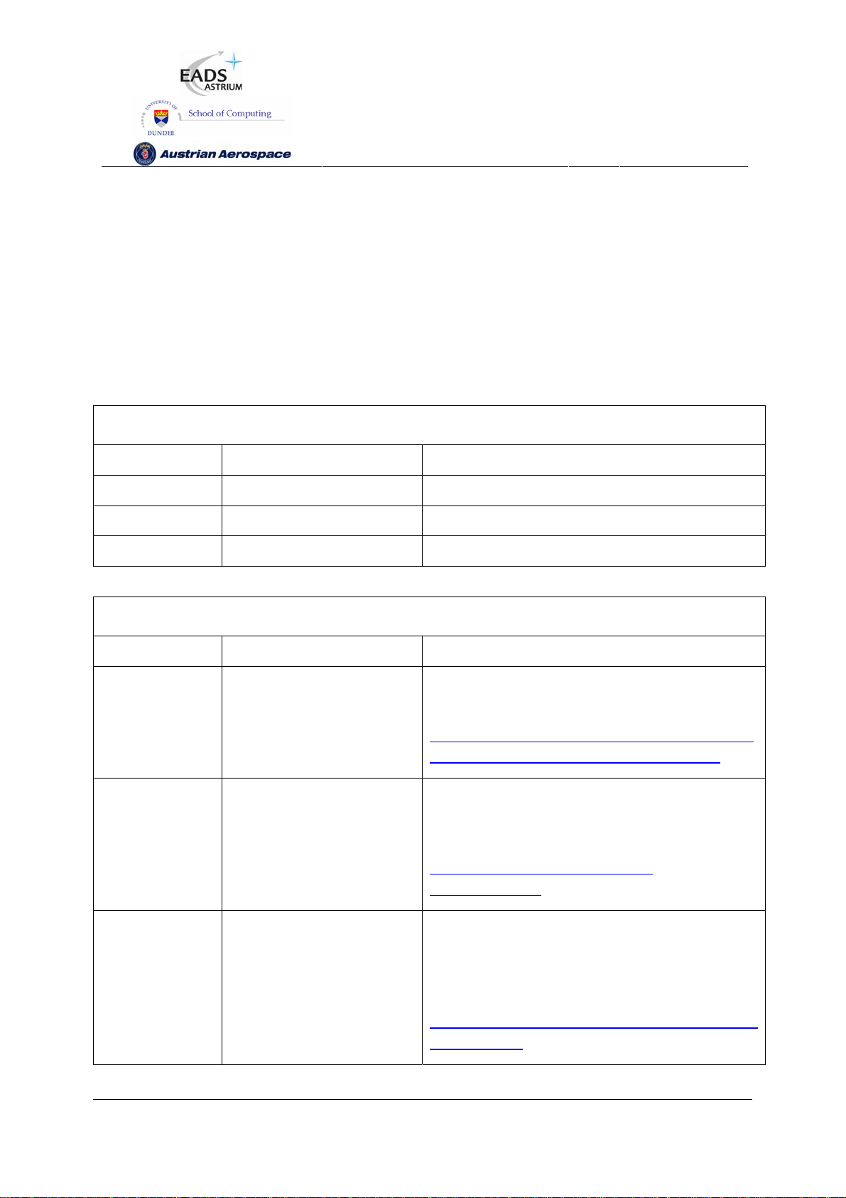
2.1 STAND-ALONE ROUTER
The SpaceWire Router may be used as a stand-alone router with up to eight SpaceWire links
connected to it. Configuration of the routing tables etc. may be done by sending SpaceWire packets
containing configuration commands to the router.
Instrument
1
Instrument
2
Instrument
3
Instrument
4
SpaceWireLinks
SpW‐10X
Router
Memory
Unit
Processor
Figure 2-1 Stand-Alone Router
In Figure 2-1 an example of use of the SpW-10X device as a stand-alone router is illustrated. There
are four instruments connected to the SpW-10X device along with a memory unit and processor. The
processor can communicate with all the instruments and memory unit to control them and is also able
to configure the SpW-10X device. The instruments can send data to the memory unit for storage or to
the processor for immediate processing. The processor can also read data from the memory for later
processing, writing the processed data back into memory. A pair of SpW-10X devices can be used to
provide a redundant configuration.
Preliminary
16
Page 17
SpW-10X
SpaceWire Router
User Manual
Ref.:
Issue:
Date:
UoD_SpW-10X_
UserManual
3.4
th
July 2008
11
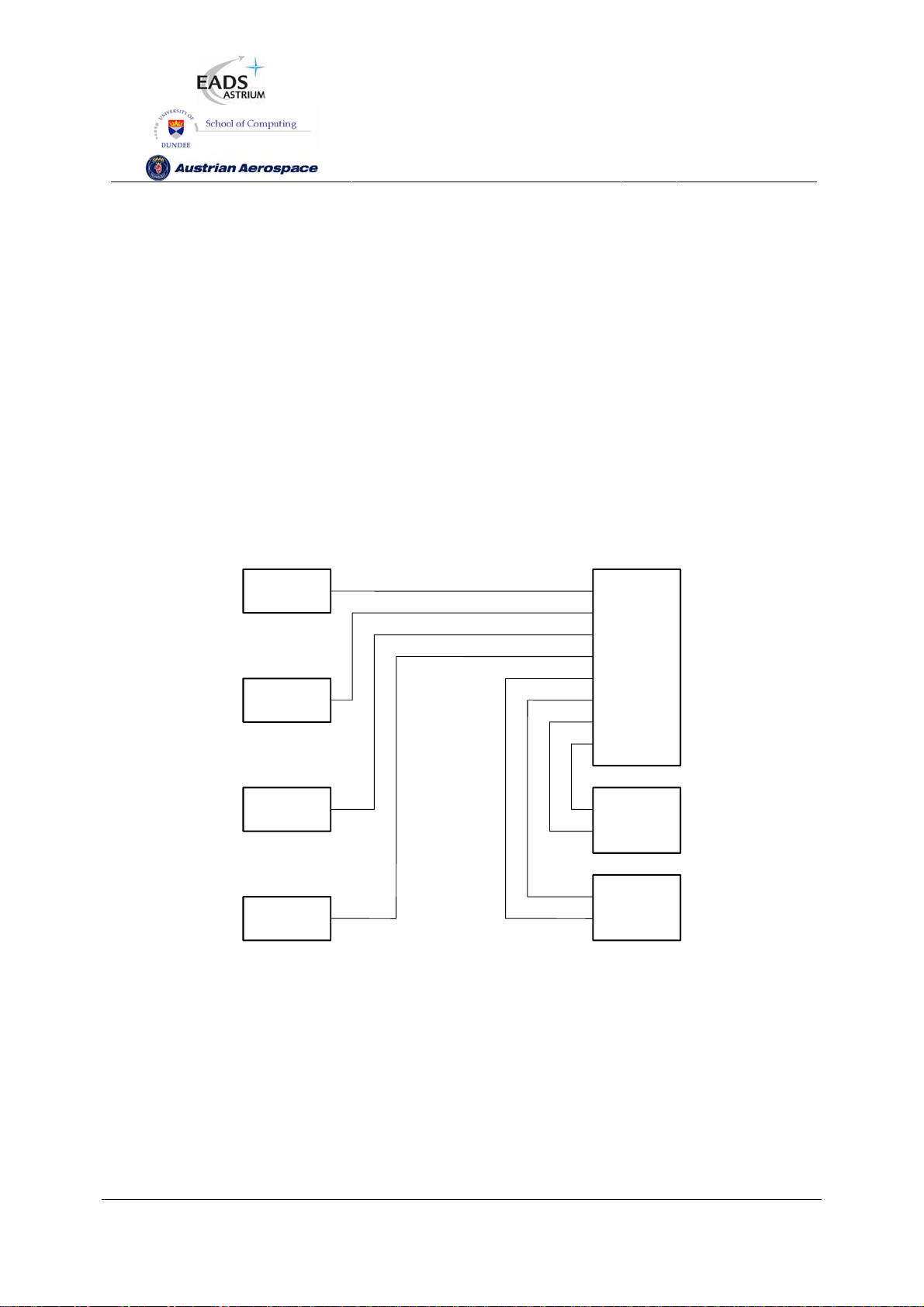
2.2 NODE INTERFACE
The SpaceWire Router has two external ports which enable the device to be used as a node interface.
The equipment to be connected to the SpaceWire network is attached to one or both external ports.
One or more SpaceWire ports are used to provide the connection into the SpaceWire network.
Unused SpaceWire ports may be disabled and their outputs deactivated to save power. In this
arrangement configuration of the routing tables and other parameters may be done by sending
configuration packets from the local host via an external port or from a remote network manager via a
SpaceWire port.
Active
SpaceWire
Links
UserFPGA
or
Processor
Disabled
SpaceWire
Links
SpW‐10X
Router
SpaceWireNode
Figure 2-2 Node Interface
In Figure 2-2 a SpW-10X router is used as an interface to a user FPGA or processor, which may be
part of a SpaceWire enabled instrument, control processor or other sub-system. The interface to the
user FPGA or processor is via the external FIFO ports of the SpW-10X router. Only three SpaceWire
links are needed for this SpaceWire node so the other five links are disabled to save power.
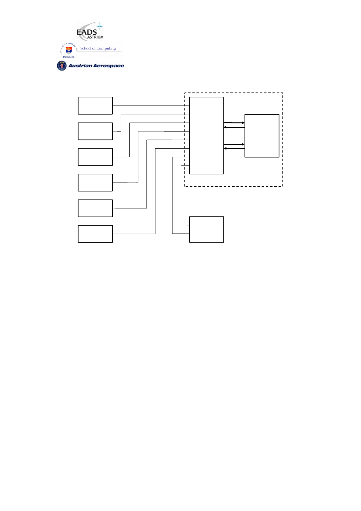
2.3 EMBEDDED ROUTER
The SpaceWire Router device can also be used to provide a node with an embedded router. In this
case the external ports are used to provide the local connections to the node and the SpaceWire ports
are used to make connections to other ports in the network. The difference between this configuration
and that of section 2.2 is just a conceptual one with the Node interface configuration normally using
fewer SpaceWire ports than the Embedded Router configuration.
Preliminary
17
Page 18
SpW-10X
SpaceWire Router
User Manual
Ref.:
Issue:
Date:
UoD_SpW-10X_
UserManual
3.4
th
July 2008
11
Instrument
1
Instrument
2
Instrument
3
Instrument
4
Instrument
5
Instrument
6
SpaceWireLinks
SpW‐10X
Router
SpaceWireNodewithEmbeddedRouter
Memory
Unit
Processor
Figure 2-3 Embedded Router
In Figure 2-3 a SpaceWire system similar to that shown in Figure 2-1 is shown with the SpW-10X
router embedded in a SpaceWire node along with a processor. The processor interfaces can interface
to the SpW-10X router using the external FIFO ports saving some SpaceWire ports for connecting to
additional instruments. For redundancy a pair of the SpaceWire nodes with embedded routers may be
used.
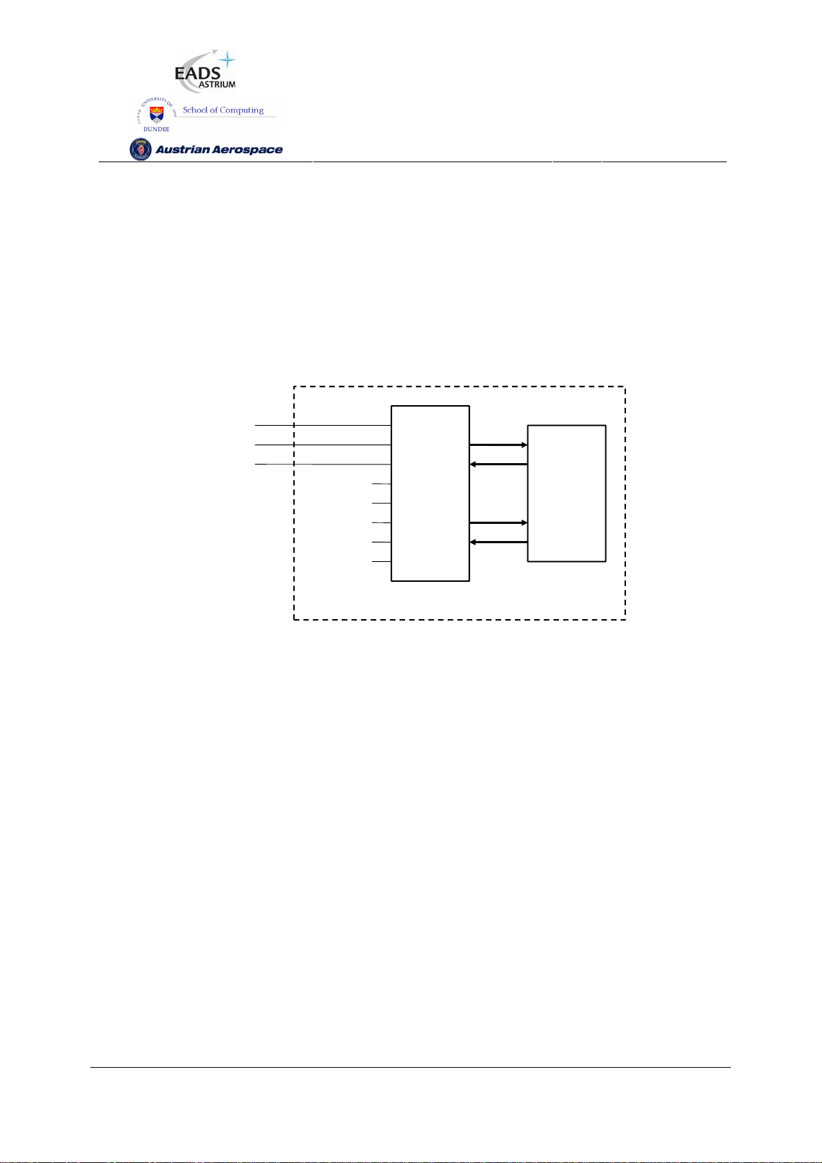
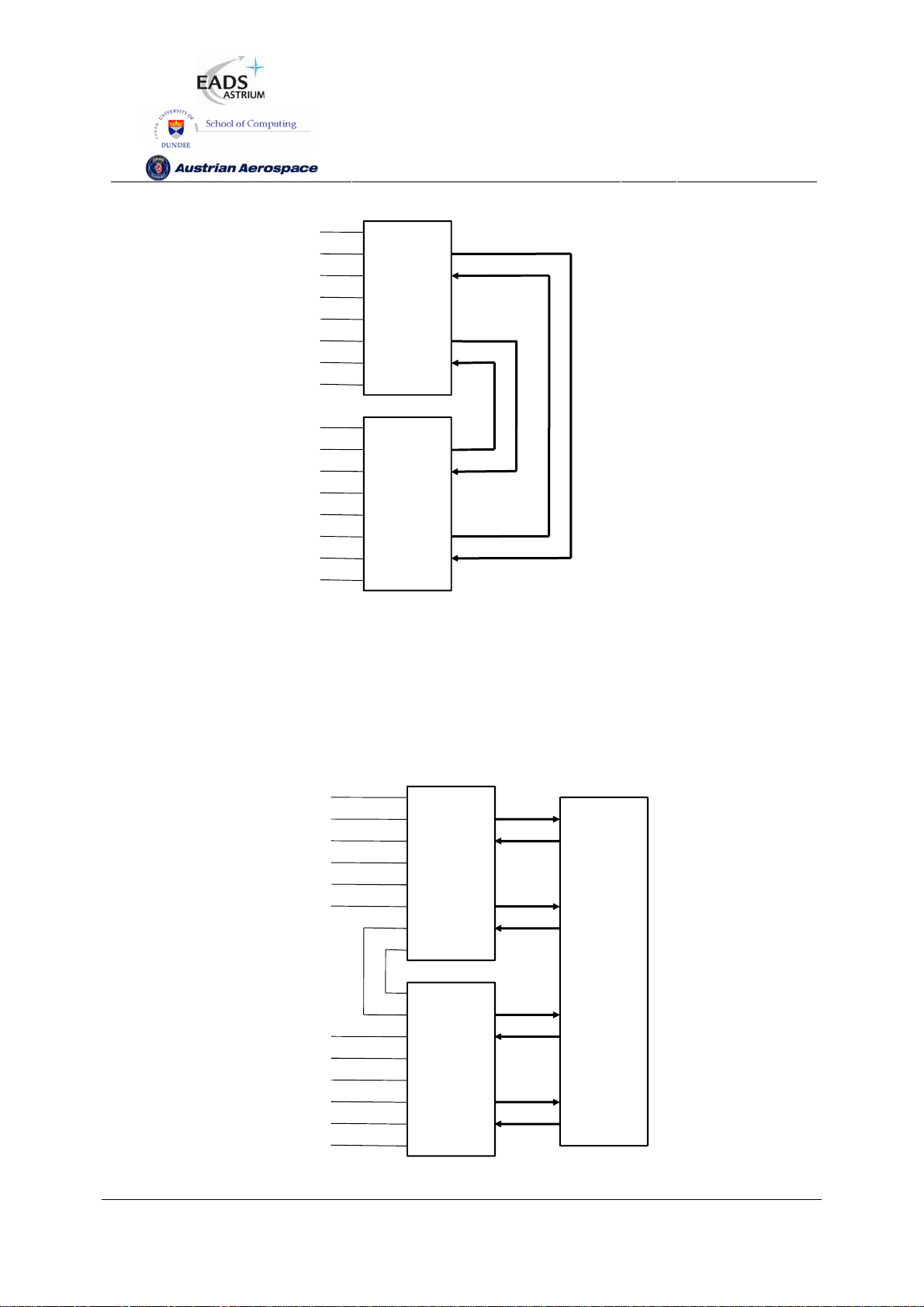
2.4 EXPANDING THE NUMBER OF ROUTER PORTS
If a routing switch with a larger number of SpaceWire (or external) ports is required then this can be
accomplished by joining together two or more routers using some of the SpaceWire links. For example
using two SpaceWire links to join together two router devices would create an effective router with
twelve SpaceWire ports and four external ports. Note, however, that an extra path addressing byte is
needed to route packets between the two routers and that there is additional routing delay.
Preliminary
18
Page 19
SpW-10X
SpaceWire Router
User Manual
Ref.:
Issue:
Date:
UoD_SpW-10X_
UserManual
3.4
th
July 2008
11
SpW‐10X
Router
SpaceWire
Ports
SpW‐10X
Router
Figure 2-4 Expanding the number of SpaceWire Ports (1)
Figure 2-4 shows a pair of SpW-10X routers connected together using the external FIFO ports to
provide a 16 port router. A small amount of external logic is required to connect the external FIFO
ports in this way. Note that the bandwidth between the two SpW-10X devices is limited by the two
external FIFO ports used to interconnect them. Each FIFO port can handle one SpaceWire packet at a
time in each direction.
SpW‐10X
Router
SpaceWire
Ports
UserFPGA
or
Processor
SpW‐10X
Router
Preliminary
19
Page 20

SpW-10X
Figure 2-5 Expanding the number of SpaceWire Ports (2)
Figure 2-5 shows two SpW-10X router devices interconnected using two of the SpaceWire ports on
each router. This leaves twelve SpaceWire ports for connection to other SpaceWire nodes. The
External FIFO ports of each router are used to connect to user logic in an FPGA or to a processing
device.
SpaceWire Router
User Manual
Ref.:
Issue:
Date:
UoD_SpW-10X_
UserManual
3.4
th
July 2008
11
Preliminary
20
Page 21

SpW-10X
SpaceWire Router
User Manual
Ref.:
Issue:
Date:
UoD_SpW-10X_
UserManual
3.4
th
July 2008
11
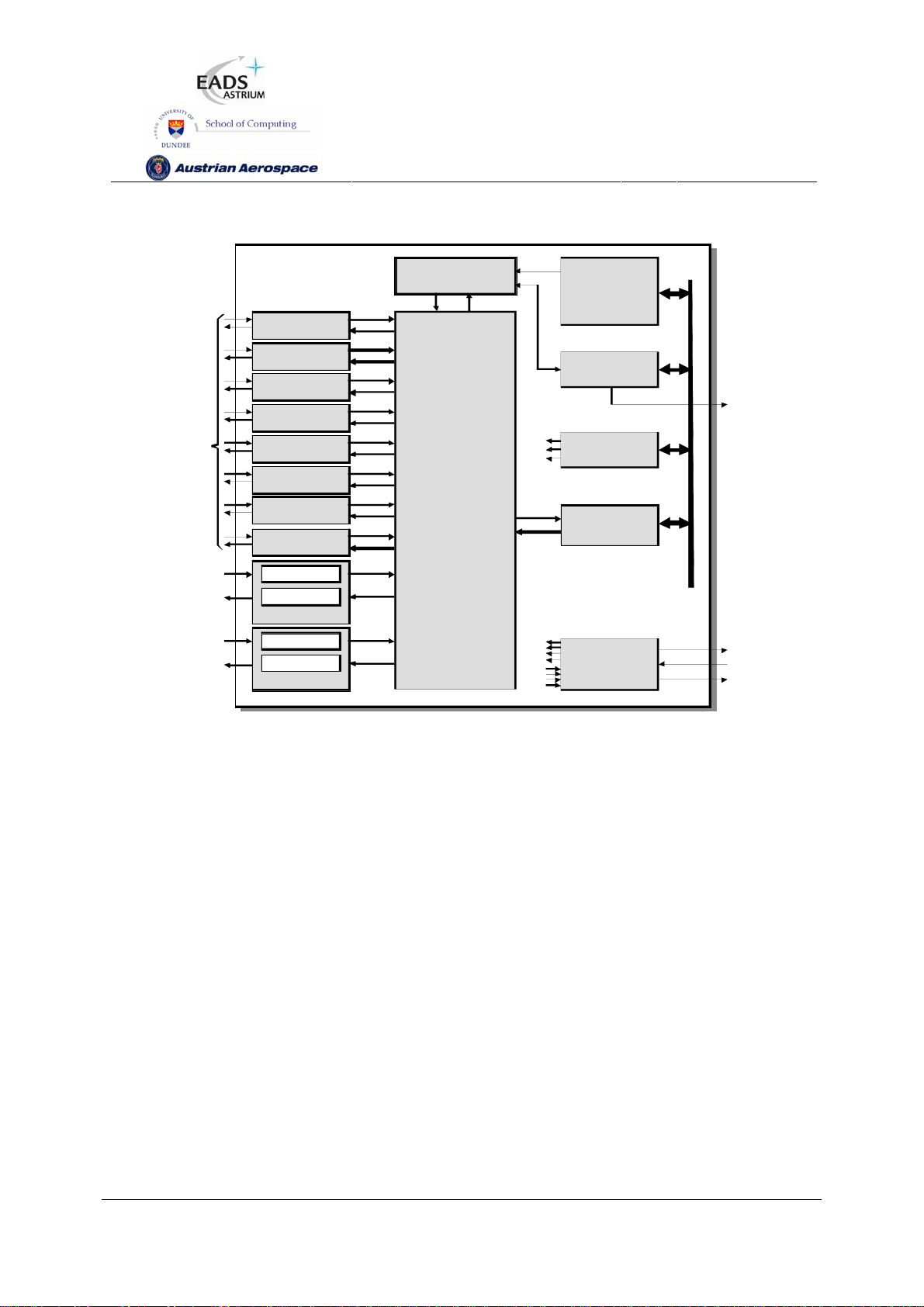
3. FUNCTIONAL OVERVIEW
A SpaceWire routing switch comprises a number of SpaceWire ports and a routing matrix. The routing
matrix enables packets arriving at one SpaceWire port to be transferred to and sent out of another port
on the routing switch. A SpaceWire routing switch is thus able to connect together many SpaceWire
nodes, providing a means of routing packets between the nodes connected to it.
The SpW-10X SpaceWire router comprises the following functional logic blocks:
• Eight SpaceWire bi-directional serial ports.
• Two external parallel input/output ports each comprising an input FIFO and an output FIFO.
• A crossbar switch connecting any input port to any output port.
• An internal configuration port accessible via the crossbar switch from the external parallel
input/output port or the SpaceWire input/output ports.
• A routing table accessible via the configuration port which holds the logical address to output
port mapping.
• Control logic to control the operation of the switch, performing arbitration and group adaptive
routing.
• Control registers than can be written and read by the configuration port and which hold control
information e.g. link operating speed.
• An external time-code interface comprising tick_in, tick_out and current tick count value.
• Internal status/error registers accessible via the configuration port.
• Watchdog timers on all ports.
• Internal status/error registers accessible via the configuration port using the RMAP protocol
[2].
• External status/error signals.
A block diagram of the routing switch is given in Figure 3-1.
Preliminary
21
Page 22
SpaceWire
Interfaces
Exte rnal
Input/O utput
SpaceWire
Port 1
SpaceWire
Port 2
SpaceWire
Port 3
SpaceWire
Port 4
SpaceWire
Port 5
SpaceWire
Port 6
SpaceWire
Port 7
SpaceWire
Port 8
Input FIFO
Ou tpu t FIFO
External Port
SpW-10X
SpaceWire Router
User Manual
Control
Logic
S tatus/Error
Cros sbar
Sw itch
Configuration
Ref.:
Issue:
Date:
Routing
Table
Regist ers
Control
Regist ers
Port
UoD_SpW-10X_
UserManual
3.4
th
July 2008
11
Status
Outputs
Input/O utput
Input FIFOExte rnal
Ou tpu t FIFO
External Port
Time-Code
In t e rface
Time-Code
Inputs /
Outputs
Figure 3-1 SpaceWire router block diagram
The following paragraphs define the SpaceWire router functional logic blocks in more detail.
3.1 SPACEWIRE PORTS
The SpaceWire router has eight bi-directional SpaceWire links each conformant with the SpaceWire
standard. Each SpaceWire link is controlled by an associated link register and routing control logic.
Network level error recovery is performed when an error is detected on the SpaceWire link as defined
in the SpaceWire standard. Packets received on SpaceWire links are routed by the routing control
logic to the configuration port, other SpaceWire link ports or the external FIFO ports. Packets with
invalid addresses are discarded by the SpaceWire router dependent on the packet address. The
SpaceWire link status is recorded in the associated link register and error status is held by the router
until cleared by a configuration command.
3.2 EXTERNAL PORTS
The SpaceWire router has two bi-directional parallel FIFO interfaces that can be used to connect the
router to an external host system. The external port FIFO is two data characters deep. Each FIFO is
Preliminary
22
Page 23

SpW-10X
written to or read from synchronously with the 30MHz system clock. An eight-bit data interface and an
extra control bit for end of packet markers are provided by each external port FIFO. Packets received
by the external port are routed by the routing control logic to the configuration port, SpaceWire link
ports or the other external port dependent on the packet address. Packets with invalid addresses are
discarded by the SpaceWire router.
SpaceWire Router
User Manual
Ref.:
Issue:
Date:
UoD_SpW-10X_
UserManual
3.4
th
July 2008
11
3.3 CONFIGURATION PORT
The SpaceWire router has one configuration port which performs read and write operations to internal
router registers. Packets are routed to the configuration port when a packet with a leading address
byte of zero is received. The Remote Memory Access Protocol (RMAP) [AD2] to access the
configuration port. A detailed description of the RMAP command packet format is provided in section
7.6. If an invalid command packet is received then the error is flagged to an associated status register
and the packet is discarded. The internal router registers are described in section 9.
3.4 ROUTING TABLE
The SpaceWire router routing table is set by the router command packets to assign logical addresses
to physical destination ports on the router. A group of destination ports can be set, in each routing
table location, to enable group adaptive routing. In group adaptive routing a packet can be routed to
its destination through one of a set of output ports dependent on which ports in the set are free to use.
When a packet is received with a logical address the routing table is checked by the routing control
logic and the packet is routed to the destination port when the port is ready.
Routing table locations are set to invalid at power on or at reset. An invalid routing address will cause
the packet to be spilled by the control logic. The routing table logical addresses can also be set to
support high priority and header deletion. High priority packets are routed before low priority packets
and header deletion of logical addresses can be used to support regional logical addressing (see
AD1).
3.5 ROUTING CONTROL LOGIC AND CROSSBAR
The routing control logic is responsible for arbitration of output ports, group adaptive routing and the
crossbar switching. Arbitration is performed when two or more source ports are requesting to use the
same destination port. A priority based arbitration scheme with two priority levels, high and low, is
used where high priority packets are routed before low priority packets. Fair arbitration is performed
on packets which have the same priority levels to ensure each packet gets equal access to the output
port.
Group adaptive routing control selects one of a number of output ports for sending out the source
packet.
Preliminary
23
Page 24

SpW-10X
The crossbar switch connects an input port to an output port allowing data to flow from the input port
to the output port. Several input ports may be connected simultaneously to several output ports all
passing data. Two or more input ports may not be connected to a single output port. The crossbar
switch is a “non-blocking” type because the connection of one input port to an output port does not
prevent another input port being connected to another output port at the same time. It is possible for
all eight input ports to be each connected to an output port so that all input ports and output ports are
being used.
SpaceWire Router
User Manual
Ref.:
Issue:
Date:
UoD_SpW-10X_
UserManual
3.4
th
July 2008
11
3.6 TIME-CODE PROCESSING
An internal time-code register is used in the router to allow the router to be a time-code master or a
time-code slave.
In master mode the time-code interface is used to provide a tick-in to the SpaceWire routing causing
time-codes to be propagated through the network. Two modes of time master operation are
supported, an automatic mode where a time-code is propagated on each external tick-in and a normal
mode where the time-code is propagated dependent on the external time-in signal.
In time-code slave mode a valid received time-code, one plus the value of the router time-code
register, causes a tick-out to be sent to the SpaceWire links and the external time-code interface. The
time-code is propagated to all time-code ports except the port on which the time-code was received. If
the time-code received is not one plus the value of the time-code register then the time-code register
is updated but the tick-out is not performed. In this way circular network paths do not cause a
constant stream of time-codes to be sent in a loop.
3.7 CONTROL/STATUS REGISTERS
The control and status registers in the SpaceWire router provide the means to control the operation of
the router, set the router configuration and parameters or monitor the status of the device. The
registers are accessed using RMAP [AD2] command packets received by the configuration port.
Preliminary
24
Page 25

SpW-10X
4. PIN LOCATIONS
The SpaceWire router package is a 196 pin MQFPF package.
Type definition:
- 3V3.................................3.3 Volt power
- GND................................Ground
- PIC................................ CMOS input
- PRD4............................ pull-down resistor (min.16kΩ, max. 80kΩ)
- PLL ............................... PLL pins
SpaceWire Router
User Manual
Ref.:
Issue:
Date:
UoD_SpW-10X_
UserManual
3.4
th
July 2008
11
- PFILVDSZP.................. LVDS cold sparing input
- PFILVDSZPB ............... LVDS cold sparing input, negative input
- PFOLVDS33ZP ............ LVDS output 3.3V
- PFOLVDS33ZPB.......... LVDS output 3.3V, negative output
- PFOLVDSREFZ ........... LVDS reference
- PO44F .......................... 4x driving strength output (fast, minimum slew rate control)
- PO22F-tri...................... 2x driving strength output with tristate (fast, minimum slew rate control)
Pin Signal Type Description
1 VDDB 3V3 Power
2 CLK PIC System clock
3 RSTN PIC Reset
4 TestIOEn PIC PRD4 Chip test pin
5 TestEn PIC PRD4 Chip test pin
6 FEEDBDIV(0) PIC PRD4 PLL divider bit 0 (LS)
7 VSSA1 GND Ground
8 VDDA1 3V3 Power
9 FEEDBDIV(1) PIC PRD4 PLL divider bit 1
10 FEEDBDIV(2) PIC PRD4 PLL divider bit 2 (MS)
11 VSSB GND Ground
12 VDDPLL PLL PLL power
13 VCOBias PLL PLL VCO bias
14 LoopFilter PLL PLL loop filter
15 VSSPLL PLL PLL ground
16 VDDB 3V3 Power
17 DINPlus(1) PFILVDSZP SpW port 1 input data +
Preliminary
25
Page 26

SpW-10X
18 DINMinus(1) PFILVDSZPB SpW port 1 input data -
19 SINPlus(1) PFILVDSZP SpW port 1 input strobe +
20 SINMinus(1) PFILVDSZPB SpW port 1 input strobe -
21 SOUTMinus(1) PFOLVDS33ZPB SpW port 1 output strobe -
22 SOUTPlus(1) PFOLVDS33ZP SpW port 1 output strobe +
23 DOUTMinus(1) PFOLVDS33ZPB SpW port 1 output data -
24 DOUTPlus(1) PFOLVDS33ZP SpW port 1 output data +
25 DINPlus(2) PFILVDSZP SpW port 2 input data +
26 DINMinus(2) PFILVDSZPB SpW port 2 input data -
27 SINPlus(2) PFILVDSZP SpW port 2 input strobe +
28 SINMinus(2) PFILVDSZPB SpW port 2 input strobe -
29 VSSB GND Ground
30 VDDB 3V3 Power
31 SOUTMinus(2) PFOLVDS33ZPB SpW port 2 output strobe -
32 SOUTPlus(2) PFOLVDS33ZP SpW port 2 output strobe +
33 DOUTMinus(2) PFOLVDS33ZPB SpW port 2 output data -
34 DOUTPlus(2) PFOLVDS33ZP SpW port 2 output data +
35 DINPlus(3) PFILVDSZP SpW port 3 input data +
36 DINMinus(3) PFILVDSZPB SpW port 3 input data -
37 SINPlus(3) PFILVDSZP SpW port 3 input strobe +
38 SINMinus(3) PFILVDSZPB SpW port 3 input strobe -
39 SOUTMinus(3) PFOLVDS33ZPB SpW port 3 output strobe -
40 SOUTPlus(3) PFOLVDS33ZP SpW port 3 output strobe +
41 VSSB GND Ground
42 VSSA2 GND Ground
43 VDDA2 3V3 Power
44 VDDB 3V3 Power
45 DOUTMinus(3) PFOLVDS33ZPB SpW port 3 output data -
46 DOUTPlus(3) PFOLVDS33ZP SpW port 3 output data +
47 DINPlus(4) PFILVDSZP SpW port 4 input data +
48 DINMinus(4) PFILVDSZPB SpW port 4 input data -
49 LVDSRef PFOLVDSREFZ LVDS reference
50 SINPlus(4) PFILVDSZP SpW port 4 input strobe +
51 SINMinus(4) PFILVDSZPB SpW port 4 input strobe -
52 SOUTMinus(4) PFOLVDS33ZPB SpW port 4 output strobe -
53 SOUTPlus(4) PFOLVDS33ZP SpW port 4 output strobe +
54 DOUTMinus(4) PFOLVDS33ZPB SpW port 4 output data -
55 DOUTPlus(4) PFOLVDS33ZP SpW port 4 output data +
56 VSSA3 GND Ground
57 VDDA3 3V3 Power
SpaceWire Router
User Manual
Ref.:
Issue:
Date:
UoD_SpW-10X_
UserManual
3.4
th
July 2008
11
Preliminary
26
Page 27

SpW-10X
58 VSSB GND Ground
59 VDDB 3V3 Power
60 DINPlus(5) PFILVDSZP SpW port 5 input data +
61 DINMinus(5) PFILVDSZPB SpW port 5 input data -
62 SINPlus(5) PFILVDSZP SpW port 5 input strobe +
63 SINMinus(5) PFILVDSZPB SpW port 5 input strobe -
64 SOUTMinus(5) PFOLVDS33ZPB SpW port 5 output strobe -
65 SOUTPlus(5) PFOLVDS33ZP SpW port 5 output strobe +
66 DOUTMinus(5) PFOLVDS33ZPB SpW port 5 output data -
67 DOUTPlus(5) PFOLVDS33ZP SpW port 5 output data +
68 DINPlus(6) PFILVDSZP SpW port 6 input data +
69 DINMinus(6) PFILVDSZPB SpW port 6 input data -
70 SINPlus(6) PFILVDSZP SpW port 6 input strobe +
71 SINMinus(6) PFILVDSZPB SpW port 6 input strobe -
72 VSSB GND Ground
73 VDDB 3V3 Power
74 SOUTMinus(6) PFOLVDS33ZPB SpW port 6 output strobe -
75 SOUTPlus(6) PFOLVDS33ZP SpW port 6 output strobe +
76 DOUTMinus(6) PFOLVDS33ZPB SpW port 6 output data -
77 DOUTPlus(6) PFOLVDS33ZP SpW port 6 output data +
78 DINPlus(7) PFILVDSZP SpW port 7 input data +
79 DINMinus(7) PFILVDSZPB SpW port 7 input data -
80 SINPlus(7) PFILVDSZP SpW port 7 input strobe +
81 SINMinus(7) PFILVDSZPB SpW port 7 input strobe -
82 SOUTMinus(7) PFOLVDS33ZPB SpW port 7 output strobe -
83 SOUTPlus(7) PFOLVDS33Z SpW port 7 output strobe +
84 VSSB GND Ground
85 VDDB 3V3 Power
86 DOUTMinus(7) PFOLVDS33ZPB SpW port 7 output data -
87 DOUTPlus(7) PFOLVDS33ZP SpW port 7 output data +
88 DINPlus(8) PFILVDSZP SpW port 8 input data +
89 DINMinus(8) PFILVDSZPB SpW port 8 input data -
90 SINPlus(8) PFILVDSZP SpW port 8 input strobe +
91 VSSA4 GND Ground
92 VDDA4 3V3 Power
93 SINMinus(8) PFILVDSZPB SpW port 8 input strobe -
94 SOUTMinus(8) PFOLVDS33ZPB SpW port 8 output strobe -
95 SOUTPlus(8) PFOLVDS33ZP SpW port 8 output strobe +
96 DOUTMinus(8) PFOLVDS33ZPB SpW port 8 output data -
97 DOUTPlus(8) PFOLVDS33ZP SpW port 8 output data +
SpaceWire Router
User Manual
Ref.:
Issue:
Date:
UoD_SpW-10X_
UserManual
3.4
th
July 2008
11
Preliminary
27
Page 28

SpW-10X
98 VSSB GND Ground
99 VDDB 3V3 Power
100 EXTOUTDATA9(0) PO44F External FIFO port 9 output data
101 EXTOUTDATA9(1) PO44F External FIFO port 9 output data
102 EXTOUTDATA9(2) PO44F External FIFO port 9 output data
103 EXTOUTDATA9(3) PO44F External FIFO port 9 output data
104 EXTOUTDATA9(4) PO44F External FIFO port 9 output data
105 VSSA5 GND Ground
106 VDDA5 3V3 Power
107 EXTOUTDATA9(5) PO44F External FIFO port 9 output data
108 VSSB GND Ground
109 VDDB 3V3 Power
110 EXTOUTDATA9(6) PO44F External FIFO port 9 output data
111 EXTOUTDATA9(7) PO44F External FIFO port 9 output data
112 EXTOUTDATA9(8) PO44F External FIFO port 9 output data
113 EXTOUTEMPTYN9 PO44F External FIFO port 9 output empty
114 EXTOUTREADN9 PIC External FIFO port 9 output read
115 EXTINDATA9(0) PIC External FIFO port 9 input data
116 EXTINDATA9(1) PIC External FIFO port 9 input data
117 EXTINDATA9(2) PIC External FIFO port 9 input data
118 EXTINDATA9(3) PIC External FIFO port 9 input data
119 EXTINDATA9(4) PIC External FIFO port 9 input data
120 EXTINDATA9(5) PIC External FIFO port 9 input data
121 EXTINDATA9(6) PIC External FIFO port 9 input data
122 EXTINDATA9(7) PIC External FIFO port 9 input data
123 EXTINDATA9(8) PIC External FIFO port 9 input data
124 EXTINFULLN9 PO44F External FIFO port 9 input full
125 VSSB GND Ground
126 VDDB 3V3 Power
127 EXTINWRITEN9 PIC External FIFO port 9 input write
128 EXTOUTDATA10(0) PO44F External FIFO port 10 output data
129 EXTOUTDATA10(1) PO44F External FIFO port 10 output data
130 EXTOUTDATA10(2) PO44F External FIFO port 10 output data
131 EXTOUTDATA10(3) PO44F External FIFO port 10 output data
132 EXTOUTDATA10(4) PO44F External FIFO port 10 output data
133 EXTOUTDATA10(5) PO44F External FIFO port 10 output data
134 VSSB GND Ground
135 VDDB 3V3 Power
136 EXTOUTDATA10(6) PO44F External FIFO port 10 output data
137 EXTOUTDATA10(7) PO44F External FIFO port 10 output data
SpaceWire Router
User Manual
Ref.:
Issue:
Date:
UoD_SpW-10X_
UserManual
3.4
th
July 2008
11
Preliminary
28
Page 29

SpW-10X
138 EXTOUTDATA10(8) PO44F External FIFO port 10 output data
139 EXTOUTEMPTYN10 PO44F External FIFO port 10 output empty
140 VSSA6 GND Ground
141 VDDA6 3V3 Power
142 EXTOUTREADN10 PIC External FIFO port 10 output read
143 EXTINDATA10(0) PIC External FIFO port 10 input data
144 EXTINDATA10(1) PIC External FIFO port 10 input data
145 EXTINDATA10(2) PIC External FIFO port 10 input data
146 EXTINDATA10(3) PIC External FIFO port 10 input data
147 EXTINDATA10(4) PIC External FIFO port 10 input data
148 EXTINDATA10(5) PIC External FIFO port 10 input data
149 EXTINDATA10(6) PIC External FIFO port 10 input data
150 EXTINDATA10(7) PIC External FIFO port 10 input data
151 EXTINDATA10(8) PIC External FIFO port 10 input data
152 EXTINFULLN10 PO44F External FIFO port 10 input full
153 EXTINWRITEN10 PIC External FIFO port 10 input wrte
154 VSSA7 GND Ground
155 VDDA7 3V3 Power
156 VSSB GND Ground
157 VDDB 3V3 Power
158 EXTTICKIN PIC Time-code tick in
159 EXTTIMEIN(0) PIC Time-code input
160 EXTTIMEIN(1) PIC Time-code input
161 EXTTIMEIN(2) PIC Time-code input
162 EXTTIMEIN(3) PIC Time-code input
163 EXTTIMEIN(4) PIC Time-code input
164 EXTTIMEIN(5) PIC Time-code input
165 EXTTIMEIN(6) PIC Time-code input
166 EXTTIMEIN(7) PIC Time-code input
167 SELEXTTIME PIC Time-code counter/input selection
168 TIMECTRRST PIC Time-code counter reset
169 EXTTICKOUT PO44F Time-code tick out
170 EXTTIMEOUT(0) PO44F Time-code output
171 EXTTIMEOUT(1) PO44F Time-code output
172 EXTTIMEOUT(2) PO44F Time-code output
173 EXTTIMEOUT(3) PO44F Time-code output
174 VSSB GND Ground
175 VDDB 3V3 Power
176 EXTTIMEOUT(4) PO44F Time-code output
177 EXTTIMEOUT(5) PO44F Time-code output
SpaceWire Router
User Manual
Ref.:
Issue:
Date:
UoD_SpW-10X_
UserManual
3.4
th
July 2008
11
Preliminary
29
Page 30

SpW-10X
178 EXTTIMEOUT(6) PO44F Time-code output
179 EXTTIMEOUT(7) PO44F Time-code output
180 STATMUXADDR(0) PIC Status output multiplexer address
181 STATMUXADDR(1) PIC Status output multiplexer address
182 STATMUXADDR(2) PIC Status output multiplexer address
183 STATMUXADDR(3) PIC Status output multiplexer address
184 VSSB GND Ground
185 VDDB 3V3 Power
186 STATMUXOUT(0) PO22F-tri PIC Status output /configuration input
187 STATMUXOUT(1) PO22F-tri PIC Status output /configuration input
188 STATMUXOUT(2) PO22F-tri PIC Status output /configuration input
189 VSSA8 GND Ground
190 VDDA8 3V3 Power
191 STATMUXOUT(3) PO22F-tri PIC Status output /configuration input
192 STATMUXOUT(4) PO22F-tri PIC Status output /configuration input
193 STATMUXOUT(5) PO22F-tri PIC Status output /configuration input
194 STATMUXOUT(6) PO22F-tri PIC Status output /configuration input
195 STATMUXOUT(7) PO22F-tri PIC Status output /configuration input
196 VSSB GND Ground
SpaceWire Router
User Manual
Ref.:
Issue:
Date:
UoD_SpW-10X_
UserManual
3.4
th
July 2008
11
Preliminary
30
Page 31

SpW-10X
SpaceWire Router
User Manual
Ref.:
Issue:
Date:
UoD_SpW-10X_
UserManual
3.4
th
July 2008
11
5. DEVICE INTERFACE
The device pins used by each interface are described in this section. There is a table for each type of
interface listing the signals in that interface. These tables have the following fields:
Pin No: The device pin number
Signal: The name of the signal
Dir: The direction of the signal; in, out or in/out
Description: An explanation of what the signal does.
Type: The type of signal
The sections below define the pin out of the SpaceWire router. Its interfaces are split into several
types, separated by headings for clarity:
5.1 Global signals: clock and reset
5.2 SpaceWire interface signals
5.3 External port signals
5.4 Time-code interface signals
5.5 Configuration signals
5.6 Reset configuration signals
5.7 Power and Ground
The following signal types are used in the SpaceWire Router:
CMOS3V3 3.3 Volt CMOS logic
LVDS Low Voltage Differential Signal
3V3 3.3 Volt power
GND Ground
5.1 GLOBAL SIGNALS
The global system clock and reset signals are listed in Table 5-1.
Preliminary
31
Page 32

SpW-10X
PinNo Signal Dir Description Type
SpaceWire Router
User Manual
Table 5-1 Global Signals
Ref.:
Issue:
Date:
UoD_SpW-10X_
UserManual
3.4
th
July 2008
11
2
3
4
5
10
9
6
CLK
RST_N
TestIOEn
TestEn
FEEDBDIV(2)
FEEDBDIV(1)
FEEDBDIV(0)
In System clock. Provides the reference clock for all
modules except the interface receivers.
In Asynchronous system reset (active low). CMOS3V3
In ASIC Test control signal; Shall be connected to
logic ‘0’ during normal operation.
Tie to ground.
In ASIC Test control signal; Shall be connected to
logic ‘0’ during normal operation.
Tie to ground.
In Set the output clock rate of the internal PLL as
follows:
“000” Æ 100MHz
“001” Æ 120MHz
“010” Æ 140MHz
“011” Æ 160MHz
“100” Æ 180MHz
“101” Æ 200MHz
“110” Æ 200MHz
“111” Æ 200MHz
See section 8.1.6 for setting the transmit rate.
CMOS3V3
CMOS3V3;
Internal pull-down
CMOS3V3;
Internal pull-down
CMOS3V3;
Internal pull-down
See section 10.1 for timing details.
WARNING
Simultaneous data/strobe transitions can occur during reset and power up. This is not a problem when
connected to SpaceWire compliant devices but is a problem when connected to IEEE-1355 devices.
5.2 SPACEWIRE SIGNALS
5.2.1 SpW-10X SpaceWire Signals
The SpaceWire interface signals are listed in Table 5-2. For further details about SpaceWire see the
SpaceWire standard [AD1]. The LVDS inputs and outputs are cold sparing [RD3].
Preliminary
32
Page 33

SpW-10X
Table 5-2 Data and Strobe SpaceWire Signals
SpaceWire Router
User Manual
Ref.:
Issue:
Date:
UoD_SpW-10X_
UserManual
3.4
th
July 2008
11
PinNo Signal
24
23
34
33
46
45
55
54
67
66
77
76
87
86
97
96
DOUTPlus(1)
DOUTMinus(1)
DOUTPlus(2)
DOUTMinus(2)
DOUTPlus(3)
DOUTMinus(3)
DOUTPlus(4)
DOUTMinus(4)
DOUTPlus(5)
DOUTMinus(5)
DOUTPlus(6)
DOUTMinus(6)
DOUTPlus(7)
DOUTMinus(7)
DOUTPlus(8)
DOUTMinus(8)
Dir Description Type
Out Differential output pair, data part of Data-Strobe
SpaceWire port 1.
Out Differential output pair, data part of Data-Strobe
SpaceWire port 2.
Out Differential output pair, data part of Data-Strobe
SpaceWire port 3.
Out Differential output pair, data part of Data-Strobe
SpaceWire port 4.
Out Differential output pair, data part of Data-Strobe
SpaceWire port 5.
Out Differential output pair, data part of Data-Strobe
SpaceWire port 6.
Out Differential output pair, data part of Data-Strobe
SpaceWire port 7.
Out Differential output pair, data part of Data-Strobe
SpaceWire port 8.
LVDS+ (P Side)
LVDS - (N Side)
LVDS+ (P Side)
LVDS - (N Side)
LVDS+ (P Side)
LVDS - (N Side)
LVDS+ (P Side)
LVDS - (N Side)
LVDS+ (P Side)
LVDS - (N Side)
LVDS+ (P Side)
LVDS - (N Side)
LVDS+ (P Side)
LVDS - (N Side)
LVDS+ (P Side)
LVDS - (N Side)
22
21
32
31
40
39
53
50
65
64
75
74
83
82
95
94
SOUTPlus(1)
SOUTMinus(1)
SOUTPlus(2)
SOUTMinus(2)
SOUTPlus(3)
SOUTMinus(3)
SOUTPlus(4)
SOUTMinus(4)
SOUTPlus(5)
SOUTMinus(5)
SOUTPlus(6)
SOUTMinus(6)
SOUTPlus(7)
SOUTMinus(7)
SOUTPlus(8)
SOUTMinus(8)
Out Differential output pair, strobe part of Data-Strobe
SpaceWire port 1.
Out Differential output pair, strobe part of Data-Strobe
SpaceWire port 2.
Out Differential output pair, strobe part of Data-Strobe
SpaceWire port 3.
Out Differential output pair, strobe part of Data-Strobe
SpaceWire port 4.
Out Differential output pair, strobe part of Data-Strobe
SpaceWire port 5.
Out Differential output pair, strobe part of Data-Strobe
SpaceWire port 6.
Out Differential output pair, strobe part of Data-Strobe
SpaceWire port 7.
Out Differential output pair, strobe part of Data-Strobe
SpaceWire port 8.
LVDS+ (P Side)
LVDS - (N Side)
LVDS+ (P Side)
LVDS - (N Side)
LVDS+ (P Side)
LVDS - (N Side)
LVDS+ (P Side)
LVDS - (N Side)
LVDS+ (P Side)
LVDS - (N Side)
LVDS+ (P Side)
LVDS - (N Side)
LVDS+ (P Side)
LVDS - (N Side)
LVDS+ (P Side)
LVDS - (N Side)
Preliminary
33
Page 34

SpW-10X
SpaceWire Router
User Manual
Ref.:
Issue:
Date:
UoD_SpW-10X_
UserManual
3.4
th
July 2008
11
17
18
25
26
35
36
47
48
60
61
68
69
78
79
88
89
19
20
27
28
37
38
50
51
62
63
70
71
80
81
90
93
DINPlus(1)
DINMinus(1)
DINPlus(2)
DINMinus(2)
DINPlus(3)
DINMinus(3)
DINPlus(4)
DINMinus(4)
DINPlus(5)
DINMinus(5)
DINPlus(6)
DINMinus(6)
DINPlus(7)
DINMinus(7)
DINPlus(8)
DINMinus(8)
SINPlus(1)
SINMinus(1)
SINPlus(2)
SINMinus(2)
SINPlus(3)
SINMinus(3)
SINPlus(4)
SINMinus(4)
SINPlus(5)
SINMinus(5)
SINPlus(6)
SINMinus(6)
SINPlus(7)
SINMinus(7)
SINPlus(8)
SINMinus(8)
In Differential input pair, data part of Data-Strobe
SpaceWire port 1.
In Differential input pair, data part of Data-Strobe
SpaceWire port 2.
In Differential input pair, data part of Data-Strobe
SpaceWire port 3.
In Differential input pair, data part of Data-Strobe
SpaceWire port 4.
In Differential input pair, data part of Data-Strobe
SpaceWire port 5.
In Differential input pair, data part of Data-Strobe
SpaceWire port 6.
In Differential input pair, data part of Data-Strobe
SpaceWire port 7.
In Differential input pair, data part of Data-Strobe
SpaceWire port 8.
In Differential input pair, strobe part of Data-Strobe
SpaceWire port 1.
In Differential input pair, strobe part of Data-Strobe
SpaceWire port 2.
In Differential input pair, strobe part of Data-Strobe
SpaceWire port 3.
In Differential input pair, strobe part of Data-Strobe
SpaceWire port 4.
In Differential input pair, strobe part of Data-Strobe
SpaceWire port 5.
In Differential input pair, strobe part of Data-Strobe
SpaceWire port 6.
In Differential input pair, strobe part of Data-Strobe
SpaceWire port 7.
In Differential input pair, strobe part of Data-Strobe
SpaceWire port 8.
LVDS+ (P Side)
LVDS - (N Side)
LVDS+ (P Side)
LVDS - (N Side)
LVDS+ (P Side)
LVDS - (N Side)
LVDS+ (P Side)
LVDS - (N Side)
LVDS+ (P Side)
LVDS - (N Side)
LVDS+ (P Side)
LVDS - (N Side)
LVDS+ (P Side)
LVDS - (N Side)
LVDS+ (P Side)
LVDS - (N Side)
LVDS+ (P Side)
LVDS - (N Side)
LVDS+ (P Side)
LVDS - (N Side)
LVDS+ (P Side)
LVDS - (N Side)
LVDS+ (P Side)
LVDS - (N Side)
LVDS+ (P Side)
LVDS - (N Side)
LVDS+ (P Side)
LVDS - (N Side)
LVDS+ (P Side)
LVDS - (N Side)
LVDS+ (P Side)
LVDS - (N Side)
See section 10.2 for timing details.
Preliminary
34
Page 35

SpW-10X
SpaceWire Router
User Manual
Ref.:
Issue:
Date:
UoD_SpW-10X_
UserManual
3.4
th
July 2008
11
5.2.2 SpaceWire Input Fail Safe Resistors
If a SpaceWire input becomes disconnected then no current flows through the termination resistor.
The differential voltage across this resistor is then zero. A small noise current, induced by electro-
magnetic interference on PCB tracks or on any part of the SpaceWire cable still attached to the
receiver, will cause a small differential voltage across the termination resistor. If this is positive the
receiver output will be logic 1 and if it the noise current flows in the other direction, giving a negative
differential voltage the receiver output will be logic 0. Just a small amount of noise is sufficient to
cause the output of the LVDS receiver to transition from 0 to 1 and back continuously. This noise can
sometime start a SpaceWire link erroneously.
To overcome this problem a small bias current can be passed through the termination resistor
generating a small positive voltage across the bias resistor and forcing the output of the LVDS
receiver to logic 1. Now any noise current smaller than this bias current will not cause the receiver to
transition. The bias current can be supplied by a pair of resistors connected to the power and ground
rails, as illustrated in Figure 5-1.
3V3
R
1
+
Disconnected
Inputs
I
n
R
I
n
I
T
b
‐
R
2
Figure 5-1 LVDS Receiver Fail-Safe Resistors
The current generator, I
PCB tracks. In Figure 5-1, I
voltage across the termination resistor R
, represents any noise picked up by the disconnected SpaceWire cable or
n
is shown as a negative current which causes a negative differential
n
. The bias resistors R1 and R2 cause a bias current , In, to
T
flow through the termination resistor. Provided that the bias current is greater than any negative noise
current the output of the LVDS receiver will be logic 1. If the noise current is positive then the LVDS
receiver output is logic 1 anyway.
The bias resistors must be chosen to give a bias current through the termination resistor greater than
any expected noise current when the input is disconnected. Note that careful PCB design can reduce
electro-magnetic interference and reduce the noise current.
Preliminary
35
Page 36

SpW-10X
The bias resistor values are determined as follows:
1. Determine the amount of noise protection required.
SpaceWire Router
User Manual
Ref.:
Issue:
Date:
UoD_SpW-10X_
UserManual
3.4
th
July 2008
11
E.g. if the maximum noise voltage expected is less than 10 mV then the bias current required is I
mV/100
Ω = 0.1 mA. Note: the bias current should be at least an order of magnitude lower than the 3
=10
b
mA current loop used for normal LVDS operation.
2. Determine the total resistance, R
E.g. R
= 3.3 V/0.1 mA = 33 kΩ. Since RT is much smaller than this value it can be ignored.
B
3. Determine the ratio of R2 to the total resistance, R
The line common mode voltage, V
, from bias supply VDD to ground, RB = VDD / Ib.
B
.
B
, should be 1.25 V so the ratio of R2 to RB is R2/RB = 1.25 V/3.3 V
cm
= 0.379.
4. Calculate the value of R2 and round down to a standard value.
E.g. R2 = 0.379 x 33 kΩ = 12.5 kΩ, so the nearest standard value is 12 kΩ (E24 series).
5. Now recalculate the value of R
E.g. R
= 12kΩ / 0.379 V = 31.6 kΩ.
B
6. Calculate the value of R1, R1 = R
to give the required line common mode voltage
B
- R2, and round to a standard value.
B
E.g. R1 = 31.6 kΩ – 12 kΩ = 19.6 kΩ, so the nearest standard value is 20 kΩ (E24 series) or 19.6 kΩ
(E48 series).
7. Check the maximum noise voltage and common mode voltage.
E.g. V
= 3.3 V x 100 Ω / 32 kΩ = 10.3 mV and Vcm = 3.3 V x 12 kΩ /32 kΩ = 1.24 V
n
If the noise on the disconnected inputs is likely to be higher than 10 mV then other resistor values
need to be calculated.
For further details see RD1 and RD2.
Preliminary
36
Page 37

SpW-10X
SpaceWire Router
User Manual
Ref.:
Issue:
Date:
UoD_SpW-10X_
UserManual
3.4
th
July 2008
11
5.2.3 Operation with 5V Powered LVDS Devices
WARNING
Since LVDS is based on a current loop it should not matter what the supply voltage is to an LVDS
device connected to the SpW-10X router. However, there is a potential problem when connecting to
devices with power supplies greater than 3.3 V, which is the supply voltage of the SpW-10X device. It
should be emphasised that during normal operation there is no problem, but if the LVDS device
connected to the SpW-10X device can fail in such a way as to put a higher voltage than 3.3 V on to
the pins of the SpW-10X device then this can cause a problem. The simplest way to overcome this
potential problem is to ensure that the LVDS devices driving the SpW-10X device are all powered by
3.3V.
5.3 EXTERNAL PORT DATA SIGNALS
The External port signals are listed in Table 5-3. The timing of these signals is shown in Figure 6-1
External port write timing specification and Figure 6-2 External port read timing specification.
Table 5-3 External Port Interface Signals
PinNo Signal Dir Description Type
112
111
110
107
104
103
102
101
100
113
114
123
122
121
EXT9_OUT_DATA(8)
EXT9_OUT_DATA (7)
EXT9_OUT_DATA(6)
EXT9_OUT_DATA(5)
EXT9_OUT_DATA(4)
EXT9_OUT_DATA(3)
EXT9_OUT_DATA(2)
EXT9_OUT_DATA(1)
EXT9_OUT_DATA(0)
EXT9_OUT_EMPTY_N Out FIFO ready signal for external output port
EXT9_OUT_READ_N In Asserted (low) to read from the external output
EXT9_IN_DATA(8)
EXT9_IN_DATA(7)
EXT9_IN_DATA(6)
Out Output data from external port number one
FIFO. Bit eight determines the type - data,
EOP or EEP. The encodings are defined as:
(8)(7......0) – Bits
(0)(dddddddd) - Data byte
(1)(XXXXXXX0) - EOP.
(1)(XXXXXXX1) - EEP.
Bit 7 is the most significant bit of the data byte.
zero. When high the FIFO has data. When low
the FIFO is empty.
port zero FIFO.
A pull-up resistor (e.g. 4k7 Ω) should be
connected to this input if External FIFO port 9
is not being used.
In Input data to external port number one FIFO.
Bit eight determines the type - data, eop or
eep. The encodings are defined as:
CMOS3V3
CMOS3V3
CMOS3V3
CMOS3V3
Preliminary
37
Page 38

SpW-10X
SpaceWire Router
User Manual
Ref.:
Issue:
Date:
UoD_SpW-10X_
UserManual
3.4
th
July 2008
11
120
119
118
117
116
115
124
127
138
137
136
133
132
131
130
129
128
139
142
151
150
149
148
147
EXT9_IN_DATA(5)
EXT9_IN_DATA(4)
EXT9_IN_DATA(3)
EXT9_IN_DATA(2)
EXT9_IN_DATA(1)
EXT9_IN_DATA(0)
EXT9_IN_FULL_N Out FIFO ready signal for external input port zero.
EXT9_IN_WRITE_N In Asserted (low) to write to the external input
EXT10_OUT_DATA(8)
EXT10_OUT_DATA(7)
EXT10_OUT_DATA(6)
EXT10_OUT_DATA(5)
EXT10_OUT_DATA(4)
EXT10_OUT_DATA(3)
EXT10_OUT_DATA(2)
EXT10_OUT_DATA(1)
EXT10_OUT_DATA(0)
EXT10_OUT_EMPTY_N Out FIFO ready signal for external output port one.
EXT10_OUT_READ_N In Asserted (low) to read from the external output
EXT10_IN_DATA(8)
EXT10_IN_DATA(7)
EXT1-_IN_DATA(6)
EXT10_IN_DATA(5)
EXT10_IN_DATA(4)
(8)(7......0) – Bits
(0)(dddddddd) - Data byte
(1)(XXXXXXX0) - EOP.
(1)(XXXXXXX1) - EEP.
Bit 7 is the most significant bit of the data byte.
Pull-up resistors (e.g. 4k7 Ω) should be
connected to these inputs if External FIFO port
9 is not being used.
When high there is space in the FIFO so it can
be written to. When low the FIFO is full.
port zero FIFO.
A pull-up resistor (e.g. 4k7 Ω) should be
connected to this input if External FIFO port 9
is not being used.
Out Output data from external port number two
FIFO . Bit eight determines the type - data,
eop or eep. The encodings are defined as:
(8)(7......0) – Bits
(0)(dddddddd) - Data byte
(1)(XXXXXXX0) - EOP.
(1)(XXXXXXX1) - EEP.
Bit 7 is the most significant bit of the data byte.
When high the FIFO has data. When low the
FIFO is empty.
port one FIFO.
A pull-up resistor (e.g. 4k7 Ω) should be
connected to this input if External FIFO port 10
is not being used.
In Input data to external port number two FIFO.
Bit eight determines the type - data, eop or
eep. The encodings are defined as:
(8)(7......0) – Bits
CMOS3V3
CMOS3V3
CMOS3V3
CMOS3V3
CMOS3V3
CMOS3V3
Preliminary
38
Page 39

SpW-10X
SpaceWire Router
User Manual
Ref.:
Issue:
Date:
UoD_SpW-10X_
UserManual
3.4
th
July 2008
11
146
145
144
143
152
153
See section 6.1 for information on the operation of the external ports and section 10.3 for timing
details.
EXT10_IN_DATA(3)
EXT10_IN_DATA(2)
EXT10_IN_DATA(1)
EXT10_IN_DATA(0)
EXT10_IN_FULL_N Out FIFO ready signal for external input port one.
EXT10_IN_WRITE_N In Asserted (low) to write to the external input
(0)(dddddddd) - Data byte
(1)(XXXXXXX0) - EOP.
(1)(XXXXXXX1) - EEP.
Bit 7 is the most significant bit of the data byte.
Pull-up resistors (e.g. 4k7 Ω) should be
connected to these inputs if External FIFO port
10 is not being used.
When high there is space in the FIFO so it can
be written to. When low the FIFO is full.
port one FIFO.
A pull-up resistor (e.g. 4k7 Ω) should be
connected to this input if External FIFO port 10
is not being used.
CMOS3V3
CMOS3V3
5.4 TIME-CODE SIGNALS
The time-code interface signals are listed in Table 5-4. The timing of this interface is shown in
Figure 6-3 and Figure 6-4.
Table 5-4 Time-Code Signals
PinNo Signal Dir Description Type
158
EXT_TICK_IN In The rising edge of the EXT_TICK_IN signal is used
to indicate when a time-code is to be sent. On the
rising edge of the EXT_TICK_IN signal the
SEL_EXT_TIME signal is sampled to determine if
the time-code value is to be provided by the internal
time-counter or by the external time input
EXT_TIME_IN(7:0).
The SEL_EXT_TIME and the EXT_TIME_IN(7:0)
signals must be set up prior to the rising edge of
EXT_TICK_IN and must be held static sometime
afterwards. See section 10.4 for timing details.
If the time-code port is not being used this input
CMOS3V3
Preliminary
39
Page 40

166
165
164
163
162
161
160
159
167
168
169
179
178
177
176
173
SpW-10X
EXT_TIME_IN(7)
EXT_TIME_IN(6)
EXT_TIME_IN(5)
EXT_TIME_IN(4)
EXT_TIME_IN(3)
EXT_TIME_IN(2)
EXT_TIME_IN(1)
EXT_TIME_IN(0)
SEL_EXT_TIME In If SEL_EXT_TIME is high on the rising edge of
TIME_CTR_RST In This signal causes the internal time-code counter to
EXT_TICK_OUT Out The falling edge of EXT_TICK_OUT is used to
EXT_TIME_OUT(7)
EXT_TIME_OUT(6)
EXT_TIME_OUT(5)
EXT_TIME_OUT(4)
EXT_TIME_OUT(3)
In EXT_TIME_IN(7:0) provides the value of the time-
Out Received time-code value which is valid when
SpaceWire Router
User Manual
should be pulled down (e.g. 4k7 Ω).
code to be distributed by the router when an
external time-code source is selected i.e. when
SEL_EXT_TIME is high on the rising edge of
EXT_TICK_IN.
When SEL_EXT_TIME is high on the rising edge of
EXT_TICK_IN the value of the time-code counter is
used for bits 5:0 of the time-code and bits 7:6 of the
EXT_TIME_IN(7:0) are used for the two control
signals, bits 7:6 of the time-code.
If the time-code port is not being used these inputs
should be pulled down (e.g. 4k7 Ω).
EXT_TICK_IN the value on EXT_TIME_IN(7:0) is
loaded into the internal time-code register and
propagated by the router.
If SEL_EXT_TIME is low on the rising edge of
EXT_TICK_IN the value to be sent in the time-code
will be taken from the internal time-code counter in
the router. The two control-bits (bits 7:6) of the
time-code will come from bits 7:6 of the
EXT_TIME_IN(7:0) input.
If the time-code port is not being used this input
should be pulled down (e.g. 4k7 Ω).
be reset to zero.
The timing parameters used for EXT_TICK_IN also
apply to the time-code counter reset signal
(TIME_CTR_RST).
If the time-code port is not being used this input
should be pulled down (e.g. 4k7 Ω).
indicated the reception of a time-code. The value of
this time-code is place on the EXT_TIME_OUT(7:0)
outputs and is valid on the rising edge of
EXT_TICK_OUT.
EXT_TICK_OUT is asserted.
The value of a received time-code is output on the
Ref.:
Issue:
Date:
UoD_SpW-10X_
UserManual
3.4
th
July 2008
11
CMOS3V3
CMOS3V3
CMOS3V3
CMOS3V3
CMOS3V3
Preliminary
40
Page 41

SpW-10X
SpaceWire Router
User Manual
Ref.:
Issue:
Date:
UoD_SpW-10X_
UserManual
3.4
th
July 2008
11
172
171
170
See section 6.2 for information on the operation of the time-code interface and section 10.4 for timing
details.
EXT_TIME_OUT(2)
EXT_TIME_OUT(1)
EXT_TIME_OUT(0)
falling edge of EXT_TICK_OUT. The
EXT_TIME_OUT(7:0) value is held until the next
time-code is output.
5.5 STATUS INTERFACE SIGNALS
The status interface signals are listed in Table 5-5.
Table 5-5 Link error indication Signals
PinNo Signal Dir Description Signal
Type
183
182
181
180
195
194
193
192
191
188
187
186
STAT_MUX_ADDR(3)
STAT_MUX_ADDR(2)
STAT_MUX_ADDR(1)
STAT_MUX_ADDR(0)
STAT_MUX_OUT(7)
STAT_MUX_OUT(6)
STAT_MUX_OUT(5)
STAT_MUX_OUT(4)
STAT_MUX_OUT(3)
STAT_MUX_OUT(2)
STAT_MUX_OUT(1)
STAT_MUX_OUT(0)
in Select the error indication status signals to be
output on STAT_MUX_OUT as defined in
Table 6-1.
These inputs should be driven or pulled up or
down (e.g. 4k7 Ω) depending on what
information is required from the status outputs.
inout Multi function pin.
Power on Configuration
After reset the STAT_MUX_OUT pins are
inputs which define the power on configuration
status of the router. The pin mappings are
listed in section 5.6.
These pins should be pulled up or down (e.g.
4k7 Ω) to provide the required power on
configuration input values.
Normal Operation
After the power on reset configuration of the
router has been read from STAT_MUX_OUT
the pins are driven as outputs by the router.
The function of these output pins is defined by
STAT_MUX_ADDR(3:0). Further details are
given in section 6.3.
CMOS3V3
CMOS3V3
Preliminary
41
Page 42
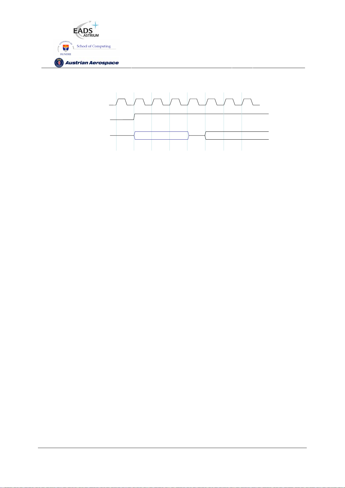
SpW-10X
SpaceWire Router
User Manual
Ref.:
Issue:
Date:
UoD_SpW-10X_
UserManual
3.4
th
July 2008
11
1234 5678
CLK
RST
STAT_MUX_OUT
POR_SIGNALS
Inputs Outputs
STAT_MUX_OUT
Figure 5-2 Configuration interface timing specification
The POR configuration signals (POR_SIGNALS) listed in Table 5-6 are loaded into the appropriate
internal configuration registers of the router after RST is de-asserted. To make sure that the POR
configuration signal values are loaded properly they should be held stable for at least three CLK
cycles following RST being de-asserted. The status output STAT_MUX_OUT is driven on the fourth
CLK cycle after RST is de-asserted.
See section 6.3 for information on the operation of the status/power on configuration interface and
section 10.5 for timing details.
5.6 RESET CONFIGURATION SIGNALS
The Reset Configuration signals are listed in Table 5-6. These signals are input on STAT_MUX_OUT
after reset to initialise the router. They are not used at any other time except immediately after reset.
The Reset Configuration signals set relevant bits in the configuration registers (see section 9).
Following reset the values of these signals are synchronously loaded into the router. The timing of the
Reset Configuration signals is illustrated in Figure 6-7.
Preliminary
42
Page 43

SpW-10X
Table 5-6 Reset Configuration Signals
Signal Dir Description Signal
SpaceWire Router
User Manual
Ref.:
Issue:
Date:
UoD_SpW-10X_
UserManual
3.4
th
July 2008
11
Type
STAT_MUX_OUT(2:0)
[maps to -> POR_TX_RATE(2:0)]
STAT_MUX_OUT(3)
[maps to ->
POR_ADDR_SELF_N
STAT_MUX_OUT(4)
[maps to ->
POR_TIMEOUT_EN_N]
STAT_MUX_OUT(5)
[maps to ->
POR_SEL_TIMEOUT0_N]
In Sets the transmitter maximum data rate after
reset. The data rate can subsequently be
changed during normal operation using port
configuration commands. The values are
listed below.
“111” – Full data rate after link start-up.
“110” – 1/2 data rate after link start-up.
“101” – 1/3 data rate after link start-up.
“100” – 1/4 data rate after link start-up.
“011” – 1/5 data rate after link start-up.
“010” – 1/6 data rate after link start-up.
“001” – 1/7 data rate after link start-up.
“000” – 1/8 data rate after link start-up.
Note: POR_TX_RATE affects all SpaceWire
ports in the router.
Note: The data rate is dependent on
FEEDBDIV at reset
In If asserted (low) after reset allows a router
port to address itself and therefore cause an
input packet to be returned through the same
input port. This mode may only be suitable for
debug and test operations.
This signal is active low.
In Power on reset signal which determines if
output port timeouts are enabled at start-up.
When asserted (low) the port timeouts are
enabled. When de-asserted (high) they are
disabled.
This signal is active low.
An external pull down resistor (e.g. 4k7 Ω) is
recommended on this pin so to enable the
watchdog timers.
In Power on reset value which determines the
initial timeout value. The following values
determine which timeout is selected at power
CMOS3V3
CMOS3V3
CMOS3V3
CMOS3V3
Preliminary
43
Page 44

STAT_MUX_OUT(6)
[maps to ->
POR_START_ON_REQ_N]
STAT_MUX_OUT(7)
[maps to ->
POR_DSBLE_ON_SILENCE_N]
SpW-10X
SpaceWire Router
User Manual
up.
‘1’ => Timeout period is ~ 60-80 us.
‘0’ => Timeout period is ~ 1.3 ms.
Timeout Period is:
‘1’ => 200x(2^2)x(10 MHz clk period)
‘0’ => 200x(2^16)x(10 MHz clk period)
An external pull down resistor (e.g. 4k7 Ω) is
recommended on this pin to provide the
longer timeout interval.
In Power on reset signal which determines if the
output ports automatically start up when they
are the destination address of a packet.
When asserted (low) the output port will
automatically start on request.
This signal is active low.
In Power on reset signal which determines if the
output ports are disabled when no activity is
detected on an output port for the current
timeout period.
When asserted (low) an output port is
disabled when it has not sent any information
for longer than the current timeout period.
This signal is active low.
Ref.:
Issue:
Date:
UoD_SpW-10X_
UserManual
3.4
th
July 2008
11
CMOS3V3
CMOS3V3
WARNING
In most onboard applications it is recommended to have Stat_mux_out(4) pulled low by default in
order to enable the watchdog timers on reset.
WARNING
When the watchdog timers are not enabled the SpaceWire and external ports can block indefinitely if,
for example, a source stops sending data in the middle of a packet. If watchdog timers are not enabled
then it must be possible for a network manager to detect blocking situations and to reset the router or
node creating the problem.
Preliminary
44
Page 45

SpW-10X
Note: The recommended method for setting the POR signals is to use external pull up/down resistors
(e.g. 4k7 Ω) in which case the timing of the POR signals is not critical.
See section 6.3 and 6.4 for further information on the operation of the status/ power on configuration
interface and section 10.5 for timing details.
SpaceWire Router
User Manual
Ref.:
Issue:
Date:
UoD_SpW-10X_
UserManual
3.4
th
July 2008
11
5.7 POWER, GROUND, PLL AND LVDS SIGNALS
5.7.1 General
The Power, Ground and special signal connections are listed in Table 5-7.
Table 5-7 Power, Ground and Special Signals
Signal Dir Description Signal
Type
Power
Ground
VCOBias
VSSPLL
VDDPLL
LoopFilter
LVDSref
- 3.3 V power for the device 3V3
- Ground connection for the device GND
PLL VCO Bias analogue
PLL Supply 3V3
PLL Supply GND
PLL Loop Filter analogue
LVDS Buffer reference analogue
5.7.2 Decoupling
The power pins should be decoupled to the ground plane. One 100 nF decoupling capacitor should be
used for each power pin.
5.7.3 LVDS Reference
An external resistor is required to provide a reference for the LVDS buffers. A resistor with a value
between 16.3 kΩ and 16.7 kΩ must be connected between LVDSref and ground.
5.7.4 PLL External Components
An internal PLL is used to provide the base transmit clock signal for the SpaceWire interfaces from the
CLK input. External components are required to implement the PLL loop filter and to provide a bias for
the PLL VCO. These components are illustrated in Figure 5-3. Note that R
connected to a quiet common ground track.
Preliminary
, C and C0 are all
VCO
45
Page 46
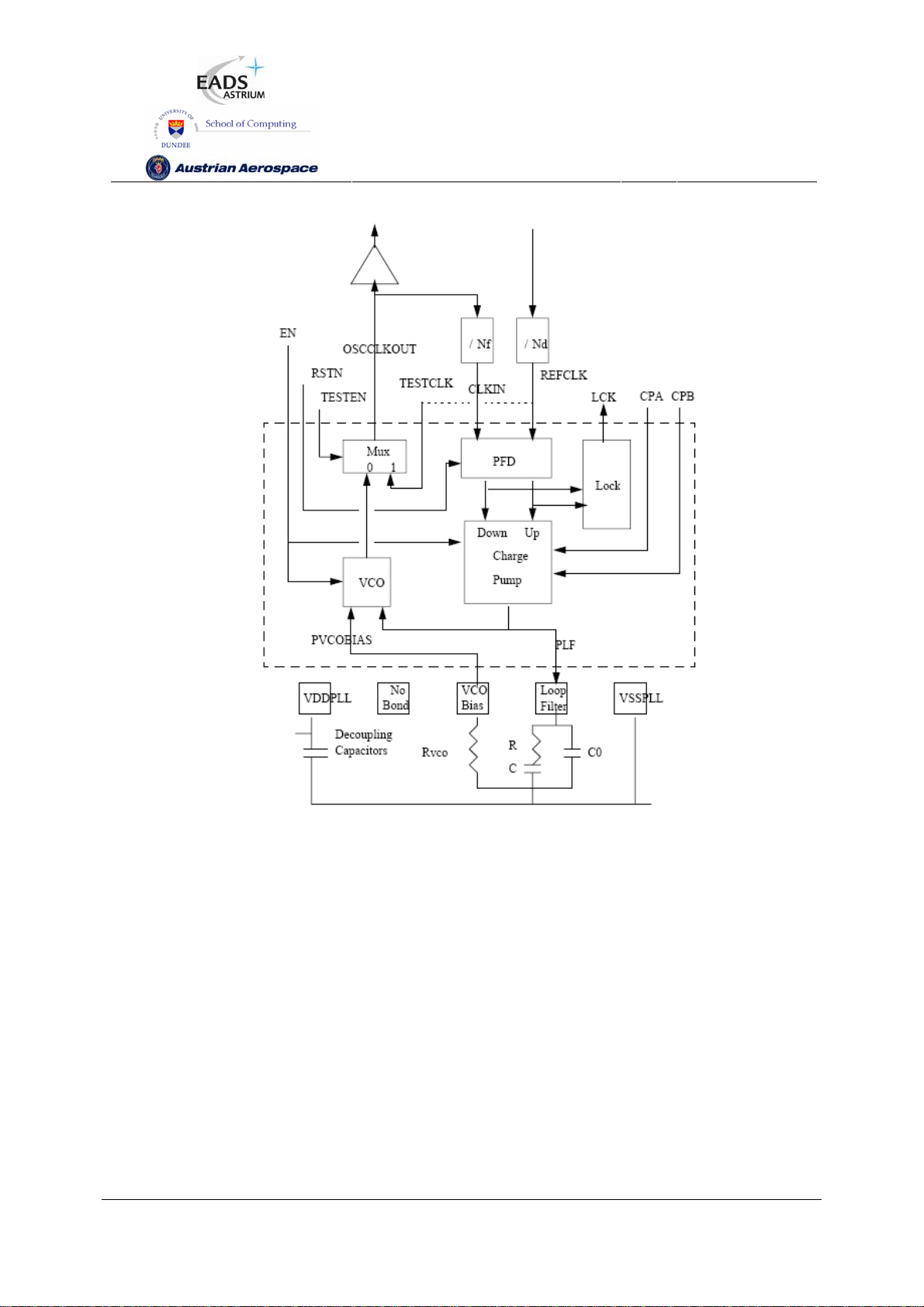
SpW-10X
SpaceWire Router
User Manual
Ref.:
Issue:
Date:
UoD_SpW-10X_
UserManual
3.4
th
July 2008
11
Figure 5-3 PLL with external components
The PLL loop filter component values to be used are
R = 10 kΩ
C = 120 pF
C0 = 3.3 pf.
The VCO bias resistor depends on the required VCO frequency range which is determined by the PLL
feedback divider (NF in Figure 5-3). The VCO bias resistor values to use are
Rvco = 4.7 kΩ for 100-150MHz (FEEDBDIV = 0b000, 0b001, or 0b010),
Rvco = 1.8 kΩ for 150MHz-200MHz (FEEDBDIV = 0b011, 0b100, 0b101 or 0b110, or 0b111).
See section 5.1 for information about the FEEDBDIV inputs.
A dedicated decoupling capacitors (100 nF and 1µF) are required for the PLL power supply.
Preliminary
46
Page 47
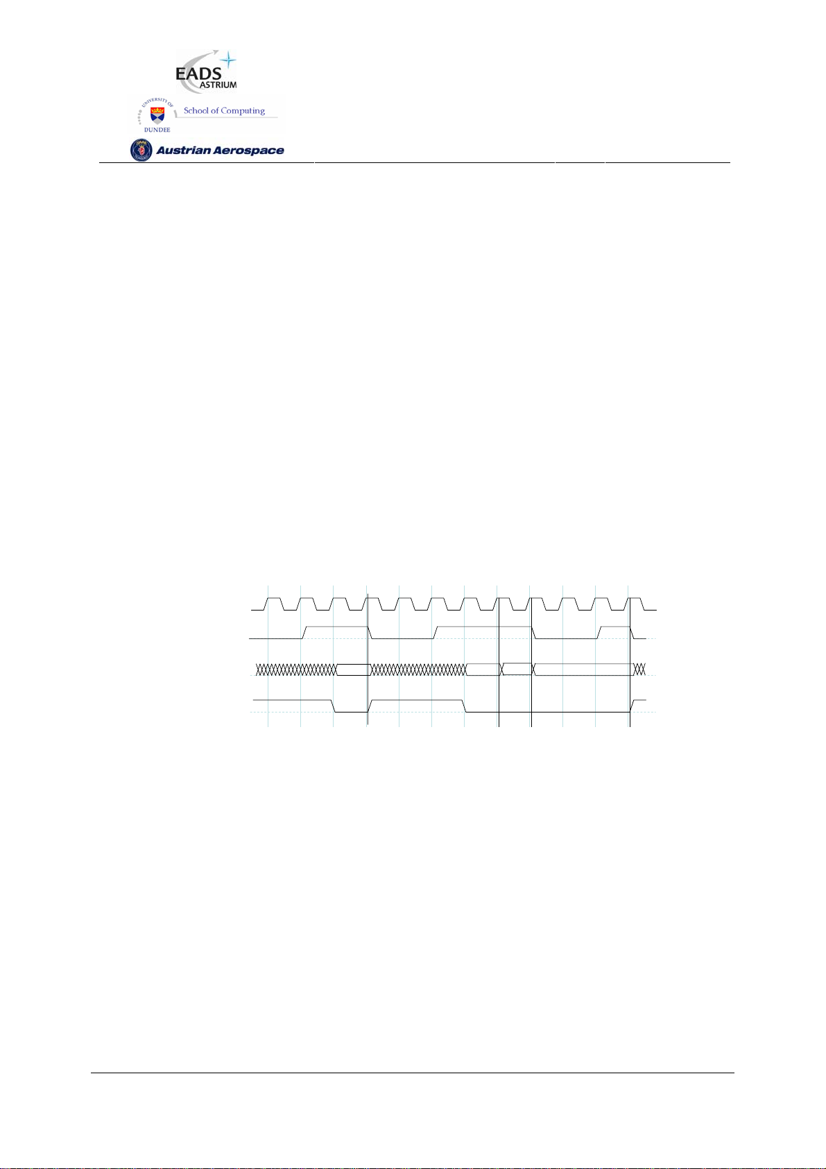
SpW-10X
SpaceWire Router
User Manual
Ref.:
Issue:
Date:
UoD_SpW-10X_
UserManual
3.4
th
July 2008
11
6. INTERFACE OPERATIONS
This section describes the operation of the external FIFO port, time-code interface and status/power
on configuration interface.
First a note on the terminology used: Signals are given a name (e.g. EXT_IN_FULL) and a logic level
(e.g. _N). The term asserted is used when the signal state reflects the signal name e.g. EXT_IN_FULL
is asserted when the external input FIFO is full. The term de-asserted is used when the signal state is
the inverse of the signal name e.g. EXT_IN_FULL is de-asserted when the external input FIFO is not
full. The logic level when a signal is asserted is indicated by the logic level extension to the signal
name. If there is no extension then when the signal is asserted it is logic 1 (high). If the _N extension
is present then when the signal is asserted it is logic 0 (low). For example, EXT_IN_FULL_N asserted
means that the physical signal is logic 0 (low) when the external input FIFO is full.
6.1 EXTERNAL PORT INTERFACE OPERATION
In this section the external port interface operation is described.
123456789101112
CLK
EXT_IN_FULL_Nx
EXT_IN_DATAx
EXT_IN_WRITE_Nx
Figure 6-1 External port write timing specification
The operation of the External port during write operations starts with the EXT_IN_FULL_N signals
being de-asserted (going high) by the router (at clock cycle 2 in Figure 6-1) to indicate to the external
system that the router has room for more data and is ready to receive it through the External port. The
External system then puts data onto the EXT_IN_DATA data lines and asserts EXT_IN_WRITE_N
(goes low) to transfer data into the External port on the next rising edge of SYSCLK. As long as there
is room for new data (EXT_IN_FULL_N is de-asserted (high) the writer access is performed as long
as EXT_IN_WRITE_N is asserted (low). If no room is available the write access is ignored (cycle 9
and 10 in Figure 6-1) and will be performed when room has become available if EXT_IN_WRITE_N is
still asserted (low). Therefore the data (EXT_IN_DATA) must be valid at that time.
DATA EOP
DATA DATA
Preliminary
47
Page 48

SpW-10X
SpaceWire Router
User Manual
Ref.:
Issue:
Date:
UoD_SpW-10X_
UserManual
3.4
th
July 2008
11
123456789101112
CLK
EXT_OUT_READ_Nx
EXT_OUT_DATAx
EXT_OUT_EMPTY_Nx
DATA1 DATA2
read
read
DATA4DATA3
read
Figure 6-2 External port read timing specification
Reading of the External port is illustrated in Figure 6-2. When data is available in the External port
FIFO then it is placed on the EXT_OUT_DATA bus and the EXT_OUT_EMPTY_N signal is asserted
to signal to the external system that data is available. This is done synchronously to the SYSCLK
signal (e.g. clock cycle 2 in Figure 6-2). When it is ready the external system asserts the
EXT_OUT_READ_N signal synchronously with the SYSCLK signal (e.g. clock cycle 3) and the data is
then read out of the external port on the next rising edge of the SYSCLK (e.g. start of clock cycle 4). If
there is no more data available in the FIFO then the EXT_OUT_EMPTY_N is de-asserted once the
data has been read. If the FIFO contains more data to transfer then the EXT_OUT_EMPTY_N
remains asserted, the new data is placed on the EXT_OUT_DATA bus and the external system can
read it as soon as it is ready. The read access is ignored if there is no data available
(EXT_OUT_EMPTY_N is active).
6.2 TIME-CODE INTERFACE OPERATION
In this section the time-code interface operation is defined.
EXT_TICK_IN
SEL_EXT_TIME
EXT_TIME_IN
Time-code inputs
EXT_TIME_IN
used for time-code
Figure 6-3 Time-Code Input Interface
Time-codes can be generated by the router on request of the external system to which it is attached. A
time-code is generated whenever the router detects a rising edge on the EXT_TICK_IN signal as
illustrated in Figure 6-3. The value of the time-code to be transmitted is either taken from the inputs or
from the time-code counter inside the router. The time-code source used depends on the value of the
Preliminary
Internal time-code
counter
used for time-code
48
Page 49

SpW-10X
SpaceWire Router
User Manual
Ref.:
Issue:
Date:
UoD_SpW-10X_
UserManual
3.4
th
July 2008
11
SEL_EXT_TIME signal when EXT_TICK_IN signal has a rising edge. If SEL_EXT_TIME is 1 then the
EXT_TIME_IN(7:0) inputs are used to provide the contents of the time-code. If SEL_EXT_TIME is 0
then the internal time-code counter provides the least-significant 6-bits of the time-code and the
EXT_TIME_IN(7:6) inputs provide the most-significant 2-bits. When using the EXT_TIME_IN(7:0)
inputs to provide the complete time-code, the time-code is only broadcast if it is a valid time-code i.e. if
the count in bits 5:0 is one more than the internal time register of the router (see SpaceWire standard
[AD1]). Note that only one router or node in a SpaceWire network should normally operate as a time
master generating time codes (see SpaceWire standard [AD1]).
EXT_TICK_OUT
EXT_TIME_OUT
Figure 6-4 Time-Code Output Interface
When a valid time-code is received by the router the value of this time-code (flags plus time value) will
be placed on the EXT_TIME_OUT outputs and the EXT_TICK_OUT signal will be set to zero. The
EXT_TICK_OUT signal is set to one a short time later, once the EXT_TIME_OUT outputs have
stabilised, to indicate that these outputs are valid. They then remain valid until the next time-code is
received and the EXT_TICK_OUT signal will be set to zero.
TIME_CTR_RST
TIME_CTR Count
Figure 6-5 Time-code reset interface
When a rising edge is detected on TIME_CTR_RST then the time-code register is reset to zero.
6.3 STATUS INTERFACE OPERATION
The STAT_MUX_ADDR signal determines the output status on STAT_MUX_OUT as shown in Figure
6-6 and in Table 6-1.
CLK
STAT_MUX_ADDR
STAT_MUX_OUT
Figure 6-6 Status Multiplexer output interface
When STAT_MUX_ADDR is stable STAT_MUX_OUT is output from after each clock edge.
Preliminary
49
Page 50

SpW-10X
Table 6-1 Multiplexed Status Pins Bit Assignment
SpaceWire Router
User Manual
Ref.:
Issue:
Date:
UoD_SpW-10X_
UserManual
3.4
th
July 2008
11
Mux
Address
0 Configuration Port Packet return address error
1 - 8 SpaceWire Ports
Status Register Status Signal Status
Output port timeout error
Checksum error
Packet too short error
Packet too long error
Packet EEP termination
Protocol byte error
Invalid address/data error
Packet Address Error
1 - 8 respectively
Output Port Timeout
Disconnect Error
Parity Error
Register
Bits
1
2
3
4
5
6
7
8
1
2
3
4
Status
Output
Bits
0
1
2
3
4
5
6
7
0
1
2
3
Escape Error
State A
State B
State C
9 - 10 External Ports
0 - 1 respectively
11 Network Discovery
Router Identity
12 Router Control Timeout Enable 0 0
Error Active
Packet Address Error
Output Port Timeout
Input Buffer Empty
Input Buffer Full
Output Buffer Empty
Output Buffer Full
Return port
Least-significant 4-bits
5
8
9
10
0
1
2
3
4
5
6
7:4
3:0
4
5
6
7
0
1
2
3
4
5
6
7:4
3:0
Preliminary
50
Page 51

SpW-10X
SpaceWire Router
User Manual
Ref.:
Issue:
Date:
UoD_SpW-10X_
UserManual
3.4
th
July 2008
11
Timeout Selection
Enable Disconnect-on-silence
Enable Start-on-Request
Enable Self-Addressing
13 Error Active Configuration Port Error
SpaceWire Ports 1-5 Error
External Ports 1,2 Error
3:1
4
5
6
0
5 :1
10 :9
3:1
4
5
6
0
5 :1
7 :6
14 Time-code Time-code 7:0 7:0
15 General Purpose Least Significant 8-bits 7:0 7:0
6.4 RESET CONFIGURATION INTERFACE OPERATION
123456789
CL K
RST N
POR_SIGNALS
POR_SS
Figure 6-7 Reset configuration interface timing specification
The POR configuration signals (POR_SIGNALS) listed above are loaded into the appropriate internal
configuration registers of the router on the first rising edge of the system clock, CLK, after RSTN is de-
asserted. To make sure that the POR configuration signal values are loaded properly STATMUXOUT
inputs must be stable from end of reset (rising edge of RSTN) till 4 CLK periods after the end of reset.
Preliminary
51
Page 52

SpW-10X
SpaceWire Router
User Manual
Ref.:
Issue:
Date:
UoD_SpW-10X_
UserManual
3.4
th
July 2008
11
7. SPACEWIRE ROUTER PACKET TYPES
This section describes how the routing control logic interprets packets.
7.1 PACKET ADDRESSES
The routing control logic interprets the first byte of each received packet as the packet address. The
packet address defines the physical ports through which the routing control logic will use to route the
packet towards its destination.
Packets which have a path address (0-31) as the first byte are always routed to the corresponding
physical port number on the router. Packets which have a logical address (32-255) are routed to
physical ports dependent on the contents of the routing table. The internal SpaceWire router routing
table can be set up to assign logical addresses to the physical ports, except the configuration port
(port 0) which can only be accessed by path addressing
The physical port addresses for the SpaceWire router and the expected packet type is defined in the
table below. The packet types can be viewed in section 0.
Table 7-1 Packet Address Mapping
Packet Address Expected Packet Type Physical Port type
0 Command packet Configuration port
1 Any type SpaceWire link port 1
2 Any type SpaceWire link port 2
3 Any type SpaceWire link port 3
4 Any type SpaceWire link port 4
5 Any type SpaceWire link port 5
6 Any type SpaceWire link port 6
7 Any type SpaceWire link port 7
8 Any type SpaceWire link port 8
9 Any type External FIFO port 1
10 Any type External FIFO port 2
11-31 N/A Invalid addresses
32-255 Any type Logical addresses
Note that logical address 255 is reserved in the SpaceWire standard [AD1].
Preliminary
52
Page 53

SpW-10X
SpaceWire Router
User Manual
Ref.:
Issue:
Date:
UoD_SpW-10X_
UserManual
3.4
th
July 2008
11
7.2 PACKET PRIORITY
Each packet which is input to the router has an associated priority level, either as a result of the
packet address or the internal routing table. Two priority levels HIGH and LOW are supported.
The table below defines the priority levels for packet addresses
Table 7-2 Packet Priority Mapping
Packet Address Packet Priority Physical Port type
0 HIGH Configuration port
1 HIGH SpaceWire link port 1
2 HIGH SpaceWire link port 2
3 HIGH SpaceWire link port 3
4 HIGH SpaceWire link port 4
5 HIGH SpaceWire link port 5
6 HIGH SpaceWire link port 6
7 HIGH SpaceWire link port 7
8 HIGH SpaceWire link port 8
9 HIGH External FIFO port 1
10 HIGH External FIFO port 2
11-31 N/A Invalid addresses
32-255 Dependent on routing table
- Default LOW
- May be configured HIGH (see section
9.3)
Logical addresses
7.3 PACKET HEADER DELETION
Header deletion is performed on packets dependent on the packet address. Packets which have path
addresses or logical addresses which have the header deletion bit set in the routing table have the
header address byte removed before the packet is routed to the destination.
The table below defines the header deletion settings for each address.
Preliminary
53
Page 54

SpW-10X
Table 7-3 Packet Header Deletion Mapping
Packet Address Header Deletion Physical Port type
0 Enabled Configuration port
1 Enabled SpaceWire link port 1
2 Enabled SpaceWire link port 2
3 Enabled SpaceWire link port 3
4 Enabled SpaceWire link port 4
5 Enabled SpaceWire link port 5
6 Enabled SpaceWire link port 6
7 Enabled SpaceWire link port 7
8 Enabled SpaceWire link port 8
9 Enabled External FIFO port 1
10 Enabled External FIFO port 2
11-31 N/A Invalid addresses
32-255 Dependent on routing table (default not
enabled)
SpaceWire Router
User Manual
Ref.:
Issue:
Date:
UoD_SpW-10X_
UserManual
3.4
th
July 2008
11
Logical addresses
Note that header deletion is always enabled for path addresses and cannot be changed by
configuration. Header deletion for logical addresses can be enabled or disabled via a configuration
register (see section 9.3).
7.4 INVALID ADDRESSES
Packets which have invalid addresses are discarded by the routing control logic. Path addresses
which are in the range 11-31, logical addresses which are set as invalid in the routing table and empty
packets (packets with no address or cargo) input to the external port are flagged as invalid packet
addresses.
A packet address error is also generated when a packet address causes the packet to be routed back
through the port on which the packet was received, i.e. a loop-back, and the router control register bit
address self is not enabled.
When an invalid address packet is received by the router then the routing control logic flags the error
to the corresponding port status register, spills the packet address, data and end of packet marker and
waits for the next packet.
Preliminary
54
Page 55

SpW-10X
SpaceWire Router
User Manual
Ref.:
Issue:
Date:
UoD_SpW-10X_
UserManual
3.4
th
July 2008
11
7.5 DATA PACKETS
Packets which have addresses in the range 1 to 255 are routed to the SpaceWire ports and the
external ports dependent on the packet address. Data packets have an address header byte a cargo
field and an end of packet marker. The normal packet structure is show below.
ADDRESS
1-255
CARGO EOP/EEP
Figure 7-1 Normal router data packets
7.6 COMMAND PACKETS
Command packets are routed to the internal configuration port when the packet address is zero.
Command packets perform write and read operations to registers in the SpaceWire router. Command
packets accepted by the SpaceWire router are in the form shown in Figure 7-2.
Configuration read packets are in the form:
ADDRESS
0
Figure 7-2 Command Packet Format
The SpaceWire router supports the Remote Memory Access Protocol (RMAP) [AD2] for configuration
of the internal router control registers and monitoring of the router status.
COMMAND EOP
The following sections define the RMAP commands which are supported and the format of the RMAP
commands used by the SpaceWire Router.
7.6.1 Supported Commands
The RMAP Command set is listed in Table 7-4 and the supported RMAP commands are defined. The
commands which are not used are depicted with a grey background.
Preliminary
55
Page 56

SpW-10X
Table 7-4 Supported RMAP Command Codes
SpaceWire Router
User Manual
Ref.:
Issue:
Date:
UoD_SpW-10X_
UserManual
3.4
th
July 2008
11
RMAP Command
Code
“0000”
“0001”
“0010” Read single address Yes
“0011” Read incrementing address Yes
“0100”
“0101”
“0110”
“0111” Read-modify-write incrementing address Yes
“1000” Write single address, no verify, no acknowledge No
“1001” Write incrementing address, no verify, no
“1010” Write single address, no verify, send
Not used
Not used
Not used
Not used
Not used
acknowledge.
acknowledge
Description Supported in SpaceWire
-
-
-
-
-
No
No
Router
“1011” Write incrementing address, no verify, send
acknowledge.
“1100” Write single address, verify data, no
acknowledge
“1101” Write incrementing address, verify data, no
acknowledge.
“1110” Write single address, verify data, send
acknowledge
“1111” Write incrementing address, verify data, send
acknowledge.
No
No
No
Yes
No
7.6.2 Read Command
The read single address characteristics of the SpaceWire router are defined in Table 7-5.
Preliminary
56
Page 57

SpW-10X
SpaceWire Router
User Manual
Ref.:
Issue:
Date:
UoD_SpW-10X_
UserManual
3.4
th
July 2008
11
Table 7-5 Read Single Address Characteristics
Action Supported/
Not Supported
Maximum number
of bytes
Non-aligned access
accepted
8-bit read NS - -
16-bit read NS - -
32-bit read S 4 No
64-bit read NS - -
Word or byte address 32-bit aligned
Accepted Logical Addresses 0xFE
Accepted destination keys 0x20 at power on.
Accepted address ranges 0x00 0000 0000 – 0x00 0000 0109
Address Incrementation No
The RMAP read single address command is supported in the SpaceWire router. The single address
command is used to read a single 32 bit register location from the router registers.
In Figure 7-3 the format of a read single address command is illustrated. The first byte received by the
SpaceWire router configuration logic is the port address followed by the destination logical address.
Fields which are depicted in bold text are expected values. Fields which are shaded are optional.
First Byte Receive d
Config Port Address
00h
Destination Logical Address
FEh
Source Path Address Source Path A ddress Source Path Address Source P ath Address
Source Logical Address Transacti on Identifier (MS) Transacti on Identifier (LS)
Read Address (MS)
00h
Data Length (MS)
00h
EOP
Bits in Packet Type / Command / Source Path Address Length Byte
MSB
Packet Type
Protocol Identifier
01h
Read Address
00h
Data Length
00h
0 01 010
Packet Type, Command
Source Path Addr Len
Read Address Read Address (LS)
Data Length (LS)
04h
Command
Destination Key
Extended Read Address
00h
Header CRC
Last Byte Received
Source Path
Address Length
Source Path Address Length
Source Path
Address Length
LSB
Figure 7-3 Read Single Address Command Format
Preliminary
57
Page 58

SpW-10X
Table 7-6 Read Single Address Command Packet Fields
Field Description Bytes
SpaceWire Router
User Manual
Ref.:
Issue:
Date:
UoD_SpW-10X_
UserManual
3.4
th
July 2008
11
Config Port
Address
Destination
Logical
Address
Protocol
Identifier
Command
Byte
Destination
Key
Source
Path
The configuration port address field routes the packet to the configuration
port of the router. The configuration port address (00h) is always present
when configuring the SpaceWire Router.
The destination logical address field is not used in the SpaceWire Router.
The SpaceWire router accepts packets which have the default destination
logical address of 254h (FEh).
The RMAP protocol identifier is 01h. 1
The command byte indicates a read single address packet. The Source path
address length fields are set to the number of source path addresses
required as defined in section 7.6.9.
The destination key identifier must match the contents of the destination key
register, see section 9.5.10. The default (power-on) destination key is 20h.
The source path address field is used to add source path addresses to the
head of the reply packet. The expected number of source path addresses is
1
1
1
1
0,4,8,12
Address
Source
Logical
Address
Transaction
Identifier
Extended
Read
Address
Read
Address
Data The data length of a read single address command shall be set to 4 to read 3
specified in the command byte. See section 7.6.9 for source path address
decoding.
The source logical address should be set to the logical address of the node
which sent the command.
The transaction identifier identifies the command packet and reply packet
with a unique number.
The extended read address is not used in the SpaceWire router and shall
always be set to zero.
The read address identifies the register address to read from. The valid read
addresses are defined in section 9.
Preliminary
1
2
1
4
58
Page 59
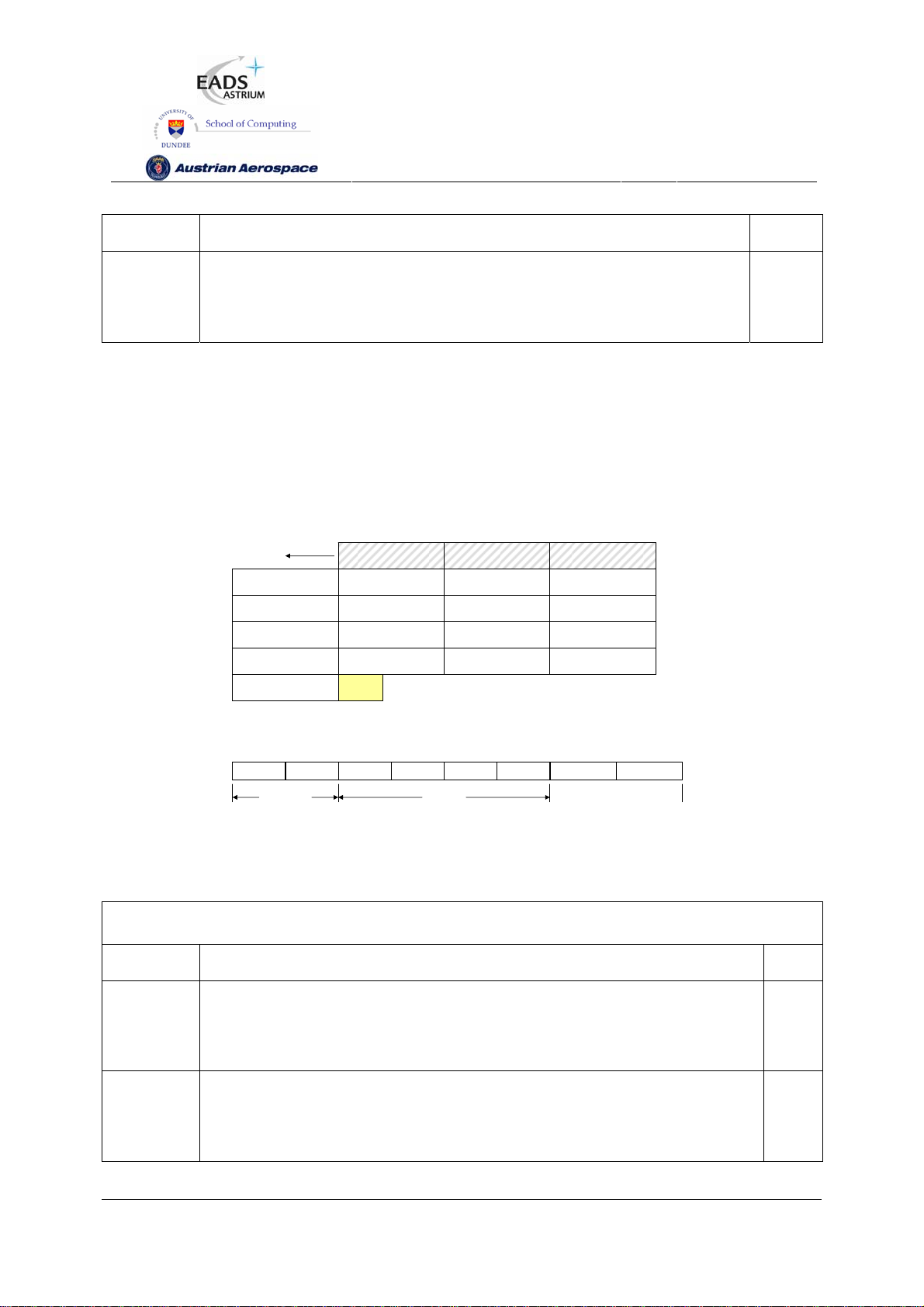
Length one 32 bit register location.
SpW-10X
SpaceWire Router
User Manual
Ref.:
Issue:
Date:
UoD_SpW-10X_
UserManual
3.4
th
July 2008
11
Header
CRC
The header CRC is the eight bit CRC code used to detect errors in the
command packet. The CRC code is checked before the command is
1
executed
In Figure 7-4 the format of the reply to a read single address command is illustrated. The first byte sent
by the SpaceWire router configuration logic is the port address followed by the destination logical
address. Fields which are depicted in bold text are expected values. Fields which are shaded are
optional. Note that the reply is always sent out of the same port as the command was received on.
The Source Path Address should not include the output port of the router being commanded as the
reply will be automatically sent out of the same port that the command arrived on. See section 7.6.8.
First byte transmitted
Source Path Address
Source Logical Address
Destination Logical Address
FEh
Data Length (MS)
00h
Data (Word 0 MSB) Data Data Data (W ord 0 LSB)
Data CRC
Protocol Identifier
01h
Transaction Identifier (MS) Transaction Identifier (LS) Reserved = 0
Data Length
00h
EOP
Last byte transmitted
Source Path Address Source Pat h Address
Packet Type, Command,
Source Path Addr Len
Data Length (LS)
04h
Status
Header CRC
Bits in Packet Type / Command / Source Address Path Length Byte
MSB
Packet Type
0 00 010
Command
Source Path
Address Length
Source Path Address Length
LSB
Source Path
Address Length
Figure 7-4 Read Single Address Reply Packet Format
Table 7-7 Read Single Address Reply Packet Fields
Field Description Bytes
Source
Path
Address
Source
Logical
Address
Optional source path addresses specified in the command packet. If no source
path addresses are specified then the first byte will be the source logical
address.
The source logical address specified in the command packet. If source path
addresses are not used then the source logical address is the address of the
return packet.
>=0
1
Preliminary
59
Page 60

SpW-10X
SpaceWire Router
User Manual
Ref.:
Issue:
Date:
UoD_SpW-10X_
UserManual
3.4
th
July 2008
11
Protocol
Identifier
Command
Byte
Status The command status is returned in this field. The command status can be
Destination
logical
address
Transaction
Identifier
Data
Length
The RMAP protocol identifier value 01h. 1
Read single address reply command byte. The packet type bits in the
command byte indicate this packet is a response packet.
command successful or an RMAP error code as defined in section 7.6.6.
The destination logical address is set to the default value FEh as the
SpaceWire router does not have a logical address.
The transaction identifier identifies the command packet and reply packet with a
unique number. The transaction identifier in the reply packet is copied from the
command packet and returned in this field, so that the command and the
corresponding reply have the same transaction identifier value.
The data length field is set to 4 bytes as this is a single read command. 3
1
1
1
2
Header
CRC
Data The data read from the registers in the device. 4
Data CRC The data CRC used to detect errors in the data part of the reply packet. See
The header CRC used to detect errors in the header part of the command
packet. See section 7.6.7 for CRC generation.
section 7.6.7 for CRC generation.
1
1
7.6.3 Read Incrementing Command
The read incrementing address characteristics of the SpaceWire router are defined in Table 7-8.
Preliminary
60
Page 61

SpW-10X
Table 7-8 Read Incrementing Address Characteristics
SpaceWire Router
User Manual
Ref.:
Issue:
Date:
UoD_SpW-10X_
UserManual
3.4
th
July 2008
11
Action Supported/
Not Supported
8-bit read NS - -
16-bit read NS - -
32-bit read S 1064 No
64-bit read NS - -
Word or byte address 32-bit aligned
Accepted Logical Addresses 0xFE
Accepted destination keys 0x20 at power on
Accepted address ranges 0x00 0000 0000 – 0x00 0000 0109
Incrementing address Incrementing address only
The RMAP read incrementing address command is supported in the SpaceWire router. The read
incrementing address is used to read a continuous block of registers from the SpaceWire router, e.g.
the complete group adaptive routing table can be read in one command or all the status registers for
the SpaceWire links can be read in one command.
Maximum number
of bytes
Non-aligned access
accepted
Preliminary
61
Page 62
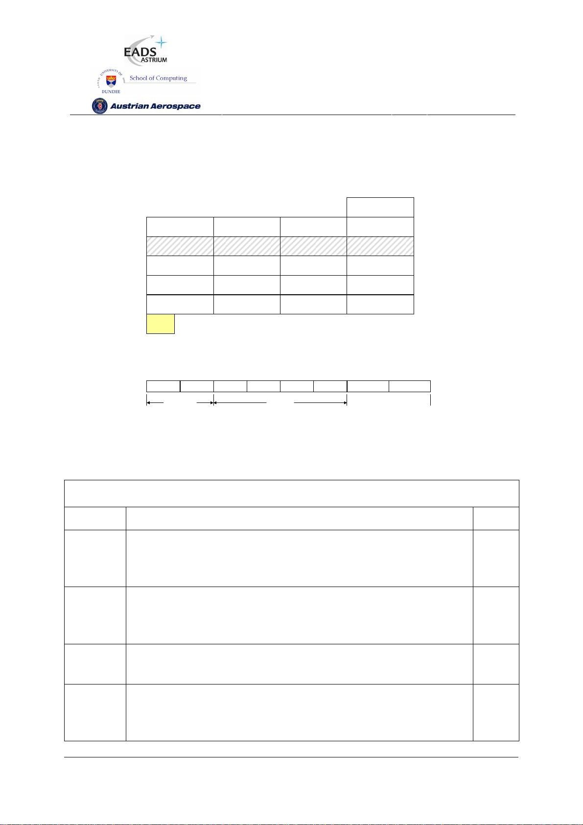
SpW-10X
SpaceWire Router
User Manual
Ref.:
Issue:
Date:
UoD_SpW-10X_
UserManual
3.4
th
July 2008
11
In Figure 7-5 the first byte received by the SpaceWire router configuration logic is the port address
followed by the destination logical address. Fields which are depicted in bold text are expected values.
Fields which are shaded are optional.
First Byte Receive d
Config Port Address
00h
Destination Logical Address
FEh
Source Path Address Source Pat h Address Source Path Address Sour ce Path Address
Source Logical Address Transacti on Identifier (MS) Transacti on Identifier (LS)
Read Address (MS)
00h
Data Length (MS)
00h
EOP
Protocol Identifier
01h
Read Address
00h
Data Length Data Lengt h (LS) Header CRC
Packet Type, Command
Source Path Addr Len
Read Address Read Address (LS)
Destination Key
Extended Read Address
Last Byte Received
00h
Bits in Packet Type / Command / Source Path Address Length Byte
MSB
Packet Type
0 01 110
Command
Source Path
Address Length
Source Path Address Length
LSB
Source Path
Address Length
Figure 7-5 Read Incrementing Address Command Format
Table 7-9 Read Incrementing Address Command Packet Fields
Field Description Bytes
Config Port
Address
The configuration port address field routes the packet to the configuration
port of the router. The configuration port address is always present when
1
configuring the SpaceWire Router.
Destination
Logical
Address
The destination logical address is not used in the SpaceWire Router. The
SpaceWire router accepts packets which have the default destination logical
address of 254h (FEh).
1
Protocol
Identifier
Command
Byte
The RMAP protocol identifier is 01h. 1
The command byte indicates a read incrementing packet. The Source path
1
address length fields are set to the number of source path addresses
required as defined in section 7.6.9.
Preliminary
62
Page 63

SpW-10X
SpaceWire Router
User Manual
Ref.:
Issue:
Date:
UoD_SpW-10X_
UserManual
3.4
th
July 2008
11
Destination
Key
Source
Path
Address
Source
Logical
Address
Transaction
Identifier
Extended
Read
Address
Read
The destination key identifier must match the contents of the destination key
register, see section 9.5.10.
The source path address field is used to add source path addresses to the
head of the reply packet. The expected number of source path addresses is
specified in the command byte. See section 7.6.9 for source path address
decoding.
The source logical address should be set to the logical address of the node
which sent the command or it should be set to the default value of FEh.
The transaction identifier identifies the command packet and reply packet
with a unique number.
The extended read address is not used in the SpaceWire router and shall
always be set to zero.
The read address identifies the start address for the read incrementing
1
0,4,8,12
1
2
1
4
Address
Data
Length
Header
CRC
command. The valid starting read addresses are defined in section 9.
The data length defines the number of bytes to read from the router. Valid
data lengths are in the range 4-1064. 1064 allows the all the router registers
to be read in one command. If the data length field is not a multiple of four
bytes then the command is rejected by the SpaceWire router.
The header CRC is the eight bit CRC code used to detect errors in the
command packet. The CRC code is checked before the command is
executed.
3
1
Preliminary
63
Page 64

SpW-10X
SpaceWire Router
User Manual
Ref.:
Issue:
Date:
UoD_SpW-10X_
UserManual
3.4
th
July 2008
11
In Figure 7-6 the format of the reply to a read incrementing address command is illustrated. The first
byte sent by the SpaceWire router configuration logic is the port address followed by the destination
logical address. Fields which are depicted in bold text are expected values. Fields which are shaded
are optional. Note that the reply is always sent out of the same port as the command was received on.
The Source Path Address should not include the output port of the router being commanded as the
reply will be automatically sent out of the same port that the command arrived on. See section 7.6.8.
First byte transmitted
Source Path Address
Source Logical Address
Destination Logical Address
FEh
Data Length (MS)
00h
Data (Word 0 MSB) Data Data Data (W ord 0 LSB )
Data (Word 1 MSB) Data Data Data (W ord 1 LSB )
Protocol Identifier
01h
Transaction Identifier (MS) Transaction Identifier (LS) Reserved = 0
Data Length D ata Le ngth (L S) Header CRC
Source Path Address Source Pat h Address
Packet Type, Command,
Source Path Addr Len
Status
Data (Word n-1 MSB) Data Data Data (W ord n-1 LSB)
Data (Word n MSB) Data Data Data (W ord n LSB )
Data CRC
Bits in Packet Type / Command / Source Address Path Length Byte
MSB
Packet Type
EOP
Last byte transmitted
0 00 110
Command
Source Path
Address Length
Source Path Address Length
Source Path
Address Length
LSB
Figure 7-6 Read Incrementing Address Reply Packet Format
Table 7-10 Read Incrementing Address Reply Packet Fields
Field Description Bytes
Source
Path
Address
Source
Optional source path addresses specified in the command packet. If no source
path addresses are specified then the first byte will be the source logical
address.
The source logical address specified in the command packet. If source path
0-12
1
Logical
Address
Protocol
Identifier
addresses are not used then the source logical address is the address of the
return packet.
The RMAP protocol identifier value 01h. 1
Preliminary
64
Page 65

SpW-10X
SpaceWire Router
User Manual
Ref.:
Issue:
Date:
UoD_SpW-10X_
UserManual
3.4
th
July 2008
11
Command
Byte
Status The command status is returned in this field. The command status can be
Destination
logical
address
Transaction
Identifier
Data
Length
Header
CRC
Read incrementing address reply command byte. The packet type bits in the
command byte indicate this packet is a reply packet.
command successful or an RMAP error code as defined in section 7.6.6.
The destination logical address is set to the default value FEh as the
SpaceWire router does not have a logical address.
The transaction identifier identifies the command packet and reply packet with a
unique number. The transaction identifier in the reply packet is copied from the
command packet and returned in this field, so that the command and the
corresponding reply have the same transaction identifier value.
The data length field is the number of bytes read from the router as specified in
the data length field of the command packet.
The header CRC used to detect errors in the header part of the command
packet. See section 7.6.7 for CRC generation.
1
1
1
2
3
1
Data The data read from the registers in the device. The data is returned in 32 bit
words starting from the address specified in read address in the command
packet.
Data CRC The data CRC used to detect errors in the data part of the reply packet. See
section 7.6.7 for CRC generation.
7.6.4 Read Modify Write Command
The read-modify-write command characteristics are defined in Table 7-8.
Table 7-11 Read-Modify-Write Command Characteristics
Action Supported/
Not Supported
8-bit read-modify-write NS - -
Maximum number
of bytes
Non-aligned access
accepted
>=4
1
16-bit read-modify-write NS - -
Preliminary
65
Page 66

SpW-10X
SpaceWire Router
User Manual
Ref.:
Issue:
Date:
UoD_SpW-10X_
UserManual
3.4
th
July 2008
11
32-bit read-modify-write S 4 No
64-bit read-modify-write NS - -
Word or byte address 32-bit aligned
Accepted Logical Addresses 0xFE
Accepted destination keys 0x20 at power on
Accepted address ranges 0x00 0000 0000 – 0x00 0000 0109
Incrementing address No
The RMAP read-modify-write command is supported by the SpaceWire router. The read modify write
command is used to set or reset a single or number of bits in a router register. The Read-Modify-Write
command is useful when it is desirable to set a link register setting without upsetting the other settings
in one command, i.e. set the start bit without modifying the data rate.
In Figure 7-7 the first byte received by the SpaceWire router configuration logic is the port address
followed by the destination logical address. Fields which are depicted in bold text are expected values.
Fields which are shaded are optional.
First byte transmitted
Destination Logical Address
FEh
Source Path Address Source Pat h Address Source Path Address S ource Path Address
Source Logical Address Transacti on Identifier (MS) Transacti on Identifier (LS)
RMW Address (MS)
00h
Data +Mask Length (MS)
00h
Data (MS) Data Data Data (LS)
Mask (MS) Mask Mask Mask (LS)
Data/Mask CRC EOP
Last byte transmitted
Bits in Packet Type / Command / Source Address Path Length Byte
MSB
Packet Type
Protocol Identifier
01h
RMW Address
00h
Data + Mask Length
00h
0 11 110
Packet Type, Command
Source Path Addr Len
RMW Address RMW Address (LS)
Data + Mask Length (LS)
08h
Command
Config Port Address
00h
Destination Key
Extended RMW Address
00h
Header CRC
Source Path
Address Length
Source Path Address Length
Source Path
Address Length
LSB
Figure 7-7 Read-Modify-Write Command Packet Format
Preliminary
66
Page 67

SpW-10X
Table 7-12 Read-Modify-Write Command Packet Fields
SpaceWire Router
User Manual
Ref.:
Issue:
Date:
UoD_SpW-10X_
UserManual
3.4
th
July 2008
11
Packet
Field
Config Port
Address
Destination
Logical
Address
Protocol
Identifier
Command
Byte
Destination
Key
Description Bytes
The configuration port address field routes the packet to the configuration
port of the router. The configuration port address is always present when
configuring the SpaceWire Router.
The destination logical address is not used in the SpaceWire Router. The
SpaceWire router accepts packets which have the default destination logical
address of 254h (FEh).
The RMAP protocol identifier is 01h. 1
The command byte indicates a read-modify-write command. The Source path
address length fields are set to the number of source path addresses
required as defined in section 7.6.9.
The destination key identifier must match the contents of the destination key
register, see section 9.5.10.
1
1
1
1
Source
Path
Address
Source
Logical
Address
Transaction
Identifier
Extended
RMW
Address
RMW
Address
Data + The data length of the read-modify-write command is 8, 4 bytes for data and 3
The source path address field is used to add source path addresses to the
head of the reply packet. The expected number of source path addresses is
specified in the command byte. See section 7.6.9 for source path address
decoding.
The source logical address should be set to the logical address of the node
which sent the command.
The transaction identifier identifies the command packet and reply packet
with a unique number.
The extended read address is not used in the SpaceWire router and shall
always be set to zero.
The read-modify-write address identifies the SpaceWire router register
address to modify. Valid RMW addresses are defined in section 9.
0,4,8,16
1
2
1
4
Preliminary
67
Page 68

SpW-10X
SpaceWire Router
User Manual
Ref.:
Issue:
Date:
UoD_SpW-10X_
UserManual
3.4
th
July 2008
11
Mask
4 bytes for the mask to modify a 32-bit register.
Length
Header
CRC
Data and
Mask
Data and
Mask CRC
The header CRC used to detect errors in the header part of the command
packet.
The data and mask values to write to the SpaceWire router. The data is
written dependent on the mask as shown in Figure 7-8.
The data and mask CRC used to detect errors in the data part of the
command packet.
1
8
1
A Read-Modify-Write command modifies the bits of a SpaceWire router register dependent on the
contents of the register (Register Data), the command data (Command Data) and the command mask
value (Mask) as follows:
Register Value = (Mask AND Command Data) OR (NOT Mask AND Register Data)
An example is shown below, the highlighted bits are set or reset by the command.
31 23
0 0 0 0 0 0 0 0 0 0 0 0 0 0 0 0
15 07
0 1 1 0 0 0 1 1 0 0 0 0 0 0 0 0
Command Data
31 23
0 0 0 0 0 0 0 0 0 0 0 0 0 0 0 0
31 23
1 1 1 1 1 1 1 1 0 0 0 0 0 0 0 0
(Mask AND Command Data) OR (NOT Mask and Register Data)
31 23
1 1 1 1 1 1 1 1 0 0 0 0 0 0 0 0
Figure 7-8 Read-Modify-Write example operation
15 07
1 1 1 1 1 1 1 1 0 0 0 0 0 0 0 0
15 07
1 0 1 0 0 1 0 0 0 0 0 0 1 0 1 0
15 07
0 1 1 0 0 0 1 1 0 0 0 0 1 0 1 0
Command Mask
Register Data
Returned to source
Data Written to Register
Preliminary
68
Page 69

SpW-10X
SpaceWire Router
User Manual
Ref.:
Issue:
Date:
UoD_SpW-10X_
UserManual
3.4
th
July 2008
11
In Figure 7-9 the format of the reply to a Read-Modify-Write command is illustrated. The first byte
received by the SpaceWire router configuration logic is the port address followed by the destination
logical address. Fields which are depicted in bold text are expected values. Fields which are shaded
are optional. Note that the reply is always sent out of the same port as the command was received on.
The Source Path Address should not include the output port of the router being commanded as the
reply will be automatically sent out of the same port that the command arrived on. See section 7.6.8.
First byte transmitted
Source Path Address
Source Logical Address
Destination Logical Address
FEh
Data Length (MS)
00h
Data (MSB) Data Da ta Data (LSB)
Data CRC EOP
Last byte transmitted
Protocol Identifier
01h
Transaction Identifier (MS) Transaction Identifier (LS)
Data Length
00h
Source Path Address Source P ath Address
Packet Type, Command,
Source Path Addr Len
Data Length (LS)
04h
Status
Reserved
00h
Header CRC
Bits in Packet Type / Command / Source Path Address Length Byte
MSB
Packet Type
0 10 110
Command
Source Path
Address Length
Source Path Address Length
LSB
Source Path
Address Length
Figure 7-9 Read-Modify-Write Reply Packet Format
Table 7-13 Read-Modify-Write Reply Packet Fields
Field Description Bytes
Source Path
Address
Optional source path addresses specified in the command packet. If no
source path addresses are specified then the first byte will be the source
0-12
logical address.
Source Logical
Address
The source logical address specified in the command packet. If source
path addresses are not used then the source logical address is the
1
address of the return packet.
Protocol Identifier The RMAP protocol identifier value 01h. 1
Command Byte Read-Modify-Write reply command byte. The packet type bits in the
1
command byte indicate this packet is a response packet.
Status The command status is returned in this field. The command status can be
1
command successful or an RMAP error code as defined in section 7.6.6.
Destination The destination logical address is set to the default value FEh as the 1
Preliminary
69
Page 70

SpW-10X
logical address SpaceWire router does not have a logical address.
SpaceWire Router
User Manual
Ref.:
Issue:
Date:
UoD_SpW-10X_
UserManual
3.4
th
July 2008
11
Transaction
Identifier
Data Length The data length field is set to 4 bytes as 4 bytes are returned in the
Header CRC The header CRC used to detect errors in the header part of the
Data The data read from the SpaceWire router registers before the modify
Data CRC The data CRC used to detect errors in the data part of the reply packet.
The transaction identifier identifies the command packet and reply packet
with a unique number. The transaction identifier in the reply packet is
copied from the command packet and returned in this field, so that the
command and the corresponding reply have the same transaction
identifier value.
Read-Modify-Write command.
command packet. See section 7.6.7 for CRC generation.
operation is performed.
See section 7.6.7 for CRC generation.
2
3
1
4
1
7.6.5 Write Command
The write command characteristics of the SpaceWire router are defined in Table 7-14.
Table 7-14 Write Command Characteristics
Action Supported/
Not Supported
8-bit write NS - -
16-bit write NS - -
32-bit write S 4 No
64-bit write NS - -
Word or byte address 32-bit aligned
Accepted Logical Addresses 0xFE
Accepted destination keys 0x20 at power on
Accepted address ranges 0x00 0000 0000 – 0x00 0000 0109
Incrementing address No
Maximum number
of bytes
Non-aligned access
accepted
Preliminary
70
Page 71

SpW-10X
SpaceWire Router
User Manual
Ref.:
Issue:
Date:
UoD_SpW-10X_
UserManual
3.4
th
July 2008
11
The RMAP write single address, with data verify and acknowledgement command is supported in the
SpaceWire router. The RMAP write command is used to write a 32 bit value into one of the SpaceWire
router registers.
In Figure 7-10 the first byte received by the SpaceWire router configuration logic is the port address
followed by the destination logical address. Fields which are depicted in bold text are expected values.
Fields which are shaded are optional.
Config Port Address
Destination Logical Address
FEh
Source Path Address Source Path Address Source Path Address Source Path Address
Source Logical Address Transaction Identifi er (MS) Transaction Identifi er (LS)
Write Address (MS)
00h
Data Length (MS)
00h
Data (MSB) Data Data Data (LSB)
Data CRC
Protocol Identifier
01h
Write Address
00h
Data Length
00h
EOP
Packet Type, Command,
Source Path Addr Len
Write Address W rite Address (LS)
Data Length (LS)
04h
00h
Destination Key
Extended Write Address
00h
Header CRC
Bits in Packet Type / Command / Source Path Address Length Byte
MSB LSB
Packet Type
1 11 010
Command Source Path Address Length
Source Path
Address Length
Source Path
Address Length
Figure 7-10 Write Single Address Command Packet
Table 7-15 Write Single Address Command Packet Fields
Field Description Bytes
Config Port
Address
The configuration port address field routes the packet to the configuration
port of the router. The configuration port address is always present when
1
configuring the SpaceWire Router.
Destination
Logical
Address
Protocol
The destination logical address is not used in the SpaceWire Router. The
1
SpaceWire router accepts packets which have the default destination logical
address of 254h (FEh).
The RMAP protocol identifier is 01h. 1
Identifier
Preliminary
71
Page 72

SpW-10X
SpaceWire Router
User Manual
Ref.:
Issue:
Date:
UoD_SpW-10X_
UserManual
3.4
th
July 2008
11
Command
Byte
Destination
Key
Source
Path
Address
Source
Logical
Address
Transaction
Identifier
Extended
The command byte indicates a write single address, with verification and
acknowledgement packet. The Source path address length fields are set to
the number of source path addresses required as defined in section 7.6.9.
The destination key identifier must match the contents of the destination key
register, see section 9.5.10.
The source path address field is used to add source path addresses to the
head of the reply packet. The expected number of source path addresses is
specified in the command byte. See section 7.6.9 for source path address
decoding.
The source logical address should be set to the logical address of the node
which sent the command.
The transaction identifier identifies the command packet and reply packet
with a unique number.
The extended write address is not used in the SpaceWire router and is
1
1
0,4,8,12
1
2
1
Write
Address
Write
Address
Data
Length
Header
CRC
Data The 32 bit data value to write to the SpaceWire router register. 4
Data CRC The data CRC used to detect errors in the data part of the command packet. 1
always expected to be zero.
The write address identifies the register to write the RMAP data. The valid
write addresses are defined in section 9.
The data length of a write single address command is expected to be 4 bytes,
to write to a 32 bit register location
The header CRC is the eight bit CRC code used to detect errors in the
command packet. The CRC code is checked before the command is
executed
4
3
1
Preliminary
72
Page 73

SpW-10X
SpaceWire Router
User Manual
Ref.:
Issue:
Date:
UoD_SpW-10X_
UserManual
3.4
th
July 2008
11
In Figure 7-11 the format of the reply to a write command is illustrated. The first byte sent by the
SpaceWire router configuration logic is the port address followed by the destination logical address.
Fields which are depicted in bold text are expected values. Fields which are shaded are optional. Note
that the reply is always sent out of the same port as the command was received on. The Source Path
Address should not include the output port of the router being commanded as the reply will be
automatically sent out of the same port that the command arrived on. See section 7.6.8.
First byte transmitted
Source Path Address
Source Logical Address
Destination Logical Address
FEh
EOP
Bits in Packet Type / Command / Source Path Address Length Byte
MSB
Packet Type
Protocol Identifier
01h
Transaction Identifier (MS) Transaction Identifier (LS) Reply CRC
1 10 010
Source Path Address Source Path Address
Packet Type, Command,
Source Path Addr Len
Address Length
Command
Status
Last byte transmitted
Source Path
Source Path Address Length
Source Path
Address Length
LSB
Figure 7-11 Write Single Address Reply Packet
Table 7-16 Write Single Address Reply Packet Fields
Field Description Bytes
Source
Path
Address
Source
Logical
Address
Protocol
Optional source path addresses specified in the command packet. If no source
path addresses are specified then the first byte will be the source logical
address.
The source logical address specified in the command packet. If source path
addresses are not used then the source logical address is the address of the
return packet.
The RMAP protocol identifier value 01h. 1
Identifier
Command
Byte
Write single address reply command byte. The packet type bits in the command
byte indicate this packet is a reply packet.
0-12
1
1
Status The command status is returned in this field. The command status can be
command successful or an RMAP error code as defined in section 7.6.6.
Destination
logical
The destination logical address is set to the default value FEh as the
SpaceWire router does not have a logical address.
Preliminary
1
1
73
Page 74

address
SpW-10X
SpaceWire Router
User Manual
Ref.:
Issue:
Date:
UoD_SpW-10X_
UserManual
3.4
th
July 2008
11
Transaction
Identifier
Header
CRC
The transaction identifier identifies the command packet and reply packet with a
unique number. The transaction identifier in the reply packet is copied from the
command packet and returned in this field, so that the command and the
corresponding reply have the same transaction identifier value.
The header CRC used to detect errors in the header part of the command
packet. See section 7.6.7 for CRC generation.
2
1
7.6.6 Command Error Response
A summary of the error conditions and the action taken is given in Table 7-17. The error conditions are
recorded in the configuration port status register.
Table 7-17 Configuration Port Errors Summary
Register Bits Description Reply
Packet
Invalid Header
CRC
The header CRC was invalid
therefore the header is
corrupted
No
Returned As Returned
RMAP
Status
Code
No Reply Packet. -
Unsupported
Protocol Error
Source Logical
Address Error
Source Path
Address
Sequence Error
Unused RMAP
command or
packet type
Invalid
Destination Key
Invalid Data
CRC
The protocol byte is not the
RMAP protocol identifier
The source logical address is
invalid (outside the range
20h-FFh)
The source path address
sequence is invalid as
specified in section 7.6.9
The command code is an
unused command code or
the packet type is invalid.
The destination key in the
command packet is invalid.
The Data CRC is invalid
therefore the data part of the
Preliminary
No
No
No
Yes Unused RMAP command
Yes Invalid Destination Key 3
Yes Invalid Data CRC 4
No Reply Packet. -
No Reply Packet. -
No Reply Packet. -
2
or packet type
74
Page 75

SpW-10X
packet is corrupted
SpaceWire Router
User Manual
Ref.:
Issue:
Date:
UoD_SpW-10X_
UserManual
3.4
th
July 2008
11
Early EOP The command packet was
terminated early with an
EOP. A reply packet is sent if
the early EOP error occurs
on the data part of the packet
Cargo too Large The expected amount of
SpaceWire cargo has been
received without receiving an
EOP marker
Early EEP The command packet was
terminated early with an
EEP. A reply packet is sent if
the early EEP error occurs
on the data part of the packet
Verify Buffer
Overrun Error
The data length field is
invalid when performing a
verified write command. The
valid length is 4 bytes of
data.
Yes Early EOP 5
Yes Cargo too large 6
Yes Early EEP 7
Yes Verify Buffer Overrun 9
Command not
implemented
Invalid Data
Length
A command code was
received which is not
supported by the SpaceWire
router. Supported command
codes are listed in F1-18.
The data length field is
invalid. A data length error is
recorded when:
1. The data length is
not a multiple of 4.
2. The data length is
zero
3. The data length is
outside the range 4-
1064 when
performing an
Yes RMAP Command not
implemented or not
authorised
Yes RMAP Command not
implemented or not
authorised
(ote 1: a Verify Buffer
Overrun error shall be
returned when the data
length is not 4 in a
verified write command.
Note 2: a Read Modify
Write Data Length error
shall be returned when
the data length is not 8.
10
10
Preliminary
75
Page 76

SpW-10X
+++
incrementing read
4. The data length is
not 4 in a verified
write command.
5. The data length is
not 8 in a read
modify write
command.
SpaceWire Router
User Manual
Ref.:
Issue:
Date:
UoD_SpW-10X_
UserManual
3.4
th
July 2008
11
Invalid Register
Address
Read Modify
Write Data
Length Error
Invalid
Destination
Logical Address
The address field is
addressing an unknown
register for a read command
or a read only register in a
write command.
The read modify write data
length is not 8
The destination logical
address is invalid. The
destination logical address is
expected to be the default
254 value
Yes RMAP Command not
implemented or not
authorised
Yes RMW Data Length Error 11
Yes Invalid Destination
Logical Address
10
12
7.6.7 Command Packet Cyclic Redundancy Check
The header and data part of an RMAP packet are protected from errors by the use of an 8 bit CRC
code. The header and data CRC is formed using the CRC-8 code used in ATM (Asynchronous
128
1
Transfer Mechanism). CRC-8 has the polynomial:
XXX
with a starting value of 00h.
Command packets received by the SpaceWire router which have an invalid header CRC are
discarded and the Invalid Header CRC bit is set in the configuration port register.
7.6.8 Local Source Path Address
The configuration reply packet shall be routed out of the router port the packet arrived on. For
example, if SpaceWire port 1 passed a configuration command to the configuration port then the reply
packet is returned to port 1.
Preliminary
76
Page 77

SpW-10X
SpaceWire Router
User Manual
Ref.:
Issue:
Date:
UoD_SpW-10X_
UserManual
3.4
th
July 2008
11
7.6.9 Source Path Address Field
The RMAP command field “source path address length” indicates the number of source path
addresses which are expected in the packet. Up to 12 source path addresses can be accepted by the
router configuration port. The source path addresses shall be decoded by the SpaceWire router as
follows.
• Leading zero source path address bytes are not returned in the RMAP reply packet.
• If the source path address contains only zero bytes the Source Path Address Sequence error
is reported, see section 7.6.6.
• After the first non zero byte in the packet any following zeros shall be treated as an error. A
source path address sequence is reported, see section 7.6.6.
The table below gives some examples of how to set the source path address length and packet
address fields for the required path addresses
Table 7-18 Source Path Address Reference Table
Source Path Address
Length
0 None None
1
1
1
2
2
2
2
1
RMAP Source Path Address fields
(FirstÆLast Transmitted)
[00 00 00 20] 20
[00 02 08 09] 02 08 09
[01 02 03 04] 01 02 03 04
[00 00 00 00] [00 00 00 02] 02
[00 00 00 00] [01 02 03 02] 01 02 03 02
[00 00 12 01] [02 B2 03 05] 12 01 02 B2 03 05
[00 32 01 02] [07 02 05 08] 32 01 02 07 02 05 08
[00 00 00 00] Invalid
Reply Path Address
(FirstÆLast Reply)
2
1
1
2
2
2
[00 00 00 00] [00 00 00 00] Invalid
[00 02 00 01] Invalid
[00 A3 00 00] Invalid
[00 02 03 00] [01 00 00 00] Invalid
[00 00 00 02] [00 00 01 00] Invalid
[00 00 00 00] [02 03 00 01] Invalid
Preliminary
77
Page 78
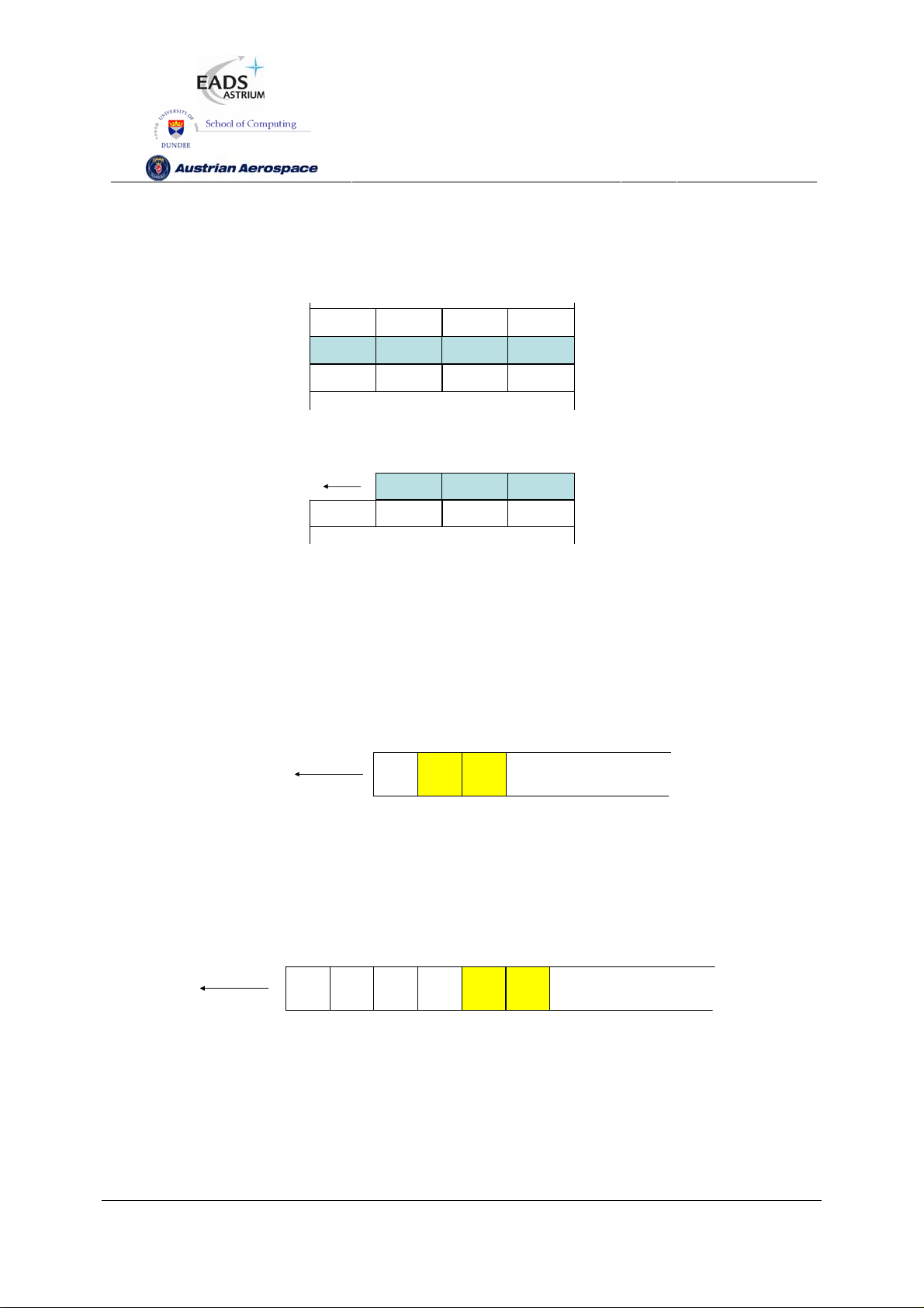
SpW-10X
SpaceWire Router
User Manual
Ref.:
Issue:
Date:
UoD_SpW-10X_
UserManual
3.4
th
July 2008
11
Figure 7-12 and Figure 7-13 illustrate how source path addresses are returned in relation to the RMAP
packet description.
Dest Logical Protocol ID Command Dest Key
00 00 04 02
Source Logical Trans ID(1) Trans ID(0) Addr ess(4)
Figure 7-12 Source Path Address field decoding
Local Source
Path Address
Source Logical Protocol ID Command Status
0204
Figure 7-13 Source Path Addresses in Reply Packet
7.6.10 Command Packet Fill Bytes
The Configuration port accepts packets which are addressed to port 0. In the RMAP command the
next byte after the destination address 0 is the destination logical address byte (which in the router is
expected to be the default 254 value). The format is shown in Figure 7-14.
Dest
Path
Logical
Address
254
Protocol ID
Address
0
Figure 7-14 Normal Configuration Packet Header Structure
To allow source nodes which have a 16, 24 or 32 bit access port then the configuration port accepts
up to three null bytes at the start of the packet. The null bytes must be zero otherwise they will be
treated as the destination logical address and an invalid destination logical address shall be recorded
if the byte is not 254. The header with fill bytes is shown in the Figure 7-15.
RMAP Header
1
Path
Address
0
Fill Byte
0
Fill Byte
0
Fill Byte
Dest
Protocol ID
Logical
0
Address
254
1
RMAP Header
Figure 7-15 Fill Bytes Configuration Header Structure
Note that the command packet fill bytes feature is specific to the SpW-10X router and is not part of the
RMAP standard.
Preliminary
78
Page 79

SpW-10X
SpaceWire Router
User Manual
Ref.:
Issue:
Date:
UoD_SpW-10X_
UserManual
3.4
th
July 2008
11
8. CONTROL LOGIC AND OPERATIONAL MODES
In this section the SpaceWire router control logic and operational modes are defined. The router
control logic determines how the SpaceWire link ports operate, how received packets are routed to
their destination and how the timeout mechanism detects packet blockages in the router.
8.1 SPACEWIRE LINK CONTROL
Each of the eight SpaceWire links has an associated SpaceWire control register. The register records
status information from each link including link error information, link state and run status (see section
9.4.3).
The SpaceWire link control bits determine how the SpaceWire link operates. The link control bits are
Auto-start (default), Link-Start, Link-Disable and Deactivate. The SpaceWire link data rate divider can
also be set in the link control register.
The following paragraphs define each of the link control functions
8.1.1 Default operating mode
The default operating mode is Auto-Start. This is the mode setting for each link after power on or
reset.
8.1.2 Auto-Start
In auto-start mode the SpaceWire port will remain inactive until a connection attempt is made by the
SpaceWire device at the other end of the SpaceWire link. The port will then start-up and make the
connection
The Auto-Start mode in conjunction with the automatic Link-Start and disable modes can help reduce
power consumption by only activating SpaceWire links when packet data is transferred. See section 0.
8.1.3 Link-Start
The link-start control bit commands the SpaceWire port to try to make a connection with a SpaceWire
device at the other end of the link. Assuming a SpaceWire device is connected to the other end of the
link the SpaceWire port will move to state Run. Data transfer can take place when the link is started
and the Link state is Run.
Preliminary
79
Page 80
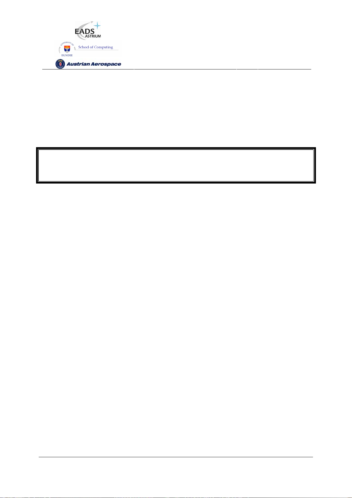
SpW-10X
SpaceWire Router
User Manual
Ref.:
Issue:
Date:
UoD_SpW-10X_
UserManual
3.4
th
July 2008
11
8.1.4 Link-Disable
The SpaceWire port can be disabled therefore rendering the link unusable. When a SpaceWire link
which is running is disabled it will disconnect from the far end and refuse connection attempts by the
far end of the link. Caution should be used when using this command for a stand alone router as
disabling all the links will leave the router unusable, except through a reset operation.
WARNING
If the link that is being used to configure the router is disabled then it will not be possible to configure
the router, unless there is another not disabled connection that can be used.
8.1.5 Automatic deactivate driver mode
The SpaceWire port deactivate bit can be set to cause the data and strobe outputs for the link to be
deactivated when the port is inactive. The deactivate mode takes effect dependent on the state of the
Auto-start and the Link-Disabled control bits in the SpaceWire port control register (see section 9.4.3)
and on the Enable Start on Request bit in the router control register (see section 9.5.3).
When Auto-start is enabled and the deactivate bit is set then the data and strobe LVDS drivers are
deactivated until the interface receives a connection attempt by an external SpaceWire device. The
drivers are then enabled until the external device disconnects the link or the SpaceWire link control bit
setup is changed.
When Start on Request is enabled and the deactivate bit is set the LVDS drivers are deactivated until
a request is made from within the router to send data out of the SpaceWire port with deactivated
output drivers i.e. a packet arriving at another port is addressed to be routed out of the SpaceWire port
with deactivated outputs. The drivers are enabled and the SpaceWire port will attempt to make a
connection with the other end of the SpaceWire link.
When Link-disable is asserted and the deactivate bit is set then the data and strobe LVDS drivers are
always deactivated as the link is not in use.
The figure below shows the effect of the deactivate bit when the link setting is Auto-start only.
Preliminary
80
Page 81

SpW-10X
SpaceWire Router
User Manual
Ref.:
Issue:
Date:
UoD_SpW-10X_
UserManual
3.4
th
July 2008
11
Disconnect
Detected
DS reset
Deactivate output
Deactivated
Deactivated
DOUT
SOUT
DIN
SIN
Deactivated
Deactivated
Return NULLs
NULL received
Activate output
Connection made Data Transfer Disconnect
Data Received
Figure 8-1 Deactivate driver operating mode
Note the DOUT deactivate driver/disable is performed one CLK cycle before the SOUT deactivate,
avoiding any simultaneous transitions on Data or Strobe.
When the LVDS drivers are deactivated the equivalent circuit of these outputs is a shown in Figure
8-2.
Vdd
3.3V
2850Ω 2850Ω
Out+
Out‐
Deactivated=
NMOS
Transist o rsoff
1725Ω 1725Ω
Vss
Figure 8-2 Deactivated LDVS driver output
When external bias resistors are being used (see section 5.2.2) and a deactivated LVDS output is
connected to a powered LVDS input with external bias resistors the equivalent circuit is as shown in
Figure 8-3.
Preliminary
81
Page 82

SpW-10X
(
SpaceWire Router
User Manual
Ref.:
Issue:
Date:
UoD_SpW-10X_
UserManual
3.4
th
July 2008
11
Vdd
2850Ω
91µA 87µA 12µA
3.3V
2850Ω 20kΩ
3.05V
+
R
10mV
=100Ω
T
99µA
3.04V
‐
16kΩ
190µA
Figure 8-3 Deactivated LDVS driver output connected to external bias network on LVDS input
Current can now flow from the 3.3 volt supply to ground. When the bias resistors for 10mV noise
margin are used, the total current flowing out of the LVDS outputs is around 200 µA as illustrated in
Figure 8-3
WARNING
The deactivate mode (see also section 9.4.3) does not tri-state the LVDS outputs. The LVDS outputs
are cold-sparing and when disabled both outputs in an LVDS differential pair are pulled up to 3.3V and
have an impedance of the order of 1 kohm. Since they are differential outputs and are both are at the
same voltage no current will flow. If, however, external noise bias resistors are being used then a
small current (around 200 µA, 0.7 mW power) can flow. This is substantially less than the normal
operating current of LVDS outputs and hence saves power.
8.1.6 Setting the SpaceWire port transmit data rate
The SpaceWire port transmit data rate is dependent on the input signal FEEDBDIV (See section 5.1),
the PLL output clock divider value TXDIV (See section 9.5.9) and the data rate divider value TXRATE
in each SpaceWire link control register (See section 9.4.3). The resultant data rate is determined by
the function.
DataRate
⎛
⎛
⎜
⎜
⎝
⎜
=
⎜
()
+
2
TXRATE
TXDIV
FEEDBDIVMHzMHz
*20100
1
+
+
1
⎜
⎝
The output of the PLL is also used to provide the 10 Mbits/s transmit clock used during SpaceWire link
initialisation.
⎞
)
⎞
⎟
⎟
⎠
⎟
2*
⎟
⎟
⎠
Preliminary
82
Page 83

SpW-10X
SpaceWire Router
User Manual
Ref.:
Issue:
Date:
UoD_SpW-10X_
UserManual
3.4
th
July 2008
11
⎞
⎞
⎟
⎟
⎠
⎟
2*
⎟
⎟
⎠
Initialisation
DataRate
Data
Rate
Duty
Cycle
MbitRate
10
⎛
⎛
⎜
⎜
⎝
⎜
=
⎜
()()
+
2
MbitDIVTX
TXDIV
FEEDBDIVMHzMHz
*20100
1
+
110
+
⎜
⎝
To provide a SpaceWire signal with a nominal 50/50 duty cycle, TXRATE and TX10MbitDIV should be
even integers.
Not all values of FEEDBDIV, TXDIV and TXRATE give valid clock signals. Table 8-1shows the
recommended values to use to achieve a range of SpaceWire transmit data rates.
Table 8-1 Setting SpaceWire Transmit Data Rate
TXRATE
TXDIV
FEEDBDIV
5 0 19 200.0 100.0 66.67 50.0 40.0 33.33 28.57 25.0 22.22 20.0 18.18 10.000 [19:21]
4 0 17 180.0 90.0 60.0 45.0 36.0 30.0 25.71 22.5 20.0 18.0 16.36 10.000 [17:19]
3 0 15 160.0 80.0 53.33 40.0 32.0 26.67 22.86 20.0 17.78 16.0 14.55 10.000 [15:17]
2 0 13 140.0 70.0 46.67 35.0 28.0 23.33 20.0 17.5 15.56 14.0 12.73 10.000 [13:15]
1 0 11 120.0 60.0 40.0 30.0 24.0 20.0 17.14 15.0 13.33 12.0 10.91 10.000 [11:13]
0 0 9 100.0 50.0 33.33 25.0 20.0 16.67 14.29 12.5 11.11 10.0 9.09 10.000 [9:11]
5 1 9 100.0 50.0 33.33 25.0 20.0 16.67 14.29 12.5 11.11 10.0 9.09 10.000 [9:11]
4 1 8 90.0 45.0 30.0 22.5 18.0 15.0 12.86 11.25 10.0 9.0 8.18 10.000 [1:1]
3 1 7 80.0 40.0 26.67 20.0 16.0 13.33 11.43 10.0 8.89 8.0 7.27 10.000 [7:9]
2 1 6 70.0 35.0 23.33 17.5 14.0 11.67 10.0 8.75 7.78 7.0 6.36 10.000 [1:1]
1 1 5 60.0 30.0 20.0 15.0 12.0 10.0 8.57 7.5 6.67 6.0 5.45 10.000 [5:7]
0 1 4 50.0 25.0 16.67 12.5 10.0 8.33 7.14 6.25 5.56 5.0 4.55 10.000 [1:1]
5 2 4 50.0 25.0 16.67 12.5 10.0 8.33 7.14 6.25 5.56 5.0 4.55 10.000 [1:1]
4 2 4 45.0 22.5 15.0 11.25 9.0 7.5 6.43 5.63 5.0 4.5 4.09 9.000 [1:1]
3 2 3 40.0 20.0 13.33 10.0 8.0 6.67 5.71 5.0 4.44 4.0 3.64 10.000 [3:5]
2 2 2 35.0 17.5 11.67 8.75 7.0 5.83 5.0 4.38 3.89 3.5 3.18 11.667 [1:1]
1 2 2 30.0 15.0 10.0 7.5 6.0 5.0 4.29 3.75 3.33 3.0 2.73 10.000 [1:1]
0 2 2 25.0 12.5 8.33 6.25 5.0 4.17 3.57 3.13 2.78 2.5 2.27 8.333 [1:1]
0 1 2 3 4 5 6 7 8 9 10
TX10MBITDIV
[1:1] [1:3] [1:1] [3:5] [1:1] [5:7] [1:1] [7:9] [1:1] [9:11] [1:1]
In Table 8-1 the values with a white background are the values that should be used. The ones in
red/shaded should not be used.
The first three columns give settings for the FEEDBDIV pins on the SpW-10X device, the TXDIV field
in the transmit clock register (see section 9.5.9) and the TX10MbitDIV field also in the transmit clock
register.
Preliminary
83
Page 84

SpW-10X
The columns header TXRATE give the SpaceWire transmit data rate obtained for various settings of
the TXRATE field in a SpaceWire port control register. The duty cycle of the SpaceWire data rate
clock is given in the row immediately underneath the TXRATE values. If the duty cycle is not 1:1 then
one bit period will be shorter than the next, as for the 10 Mbits/s data rate. Again permitting a
maximum 10% variation in the bit periods allows a worst case duty cycle of 9:11. The valid transmit
data rate values which have corresponding valid 10Mbits/s data rate values have a white background
in the table. The TXRATE divider is actually a 7-bit field so there are many more possible columns
under TXRATE. All of these TXRATE columns would give valid transmit data rates. The values for
these additional columns can be calculated using the formulae given above.
The Initialisation Data Rate columns of the table give the frequency of the 10 Mbits/s clock used
during initialisation and the duty cycle of adjacent bit periods.. The data rate must be in the range 9-11
Mbits/s. The actual 10 Mbits/s data rate is produced from a 5 MHz clock signal using double data rate
outputs to save power. The duty cycle column gives the duty cycle of the 5 MHz start up data/strobe
clock. If this is not 1:1 then one data bit period will be shorter than the next data bit period. This can
reduce skew tolerance and hence the maximum operating speed of the SpaceWire ports. Taking a
limit of 10% of the bit period allows the use of 10Mbit/s clocks with a duty cycle of 9:11 as the worst
case. The corresponding setting for the TX10MbitDIV field in the transmit clock register (see section
9.5.9) is given in the third column. Only the rows with valid Initialisation data rate and duty cycle
should be used.
SpaceWire Router
User Manual
Ref.:
Issue:
Date:
UoD_SpW-10X_
UserManual
3.4
th
July 2008
11
The following steps should be followed to set a particular transmit data rate using values from Table
8-1:
1. Select the required SpaceWire transmit data rate from Table 8-1.Only values with a white
background in the table should be used. Values with a red/shaded background should not be used.
2. Set the FEEDBDIV pins on the SpW-10X device to the corresponding value in Table 8-1.
2. Set the TXDIV and TX10MbitDIV fields in the transmit clock control register (see section 9.5.9)
using values from Table 8-1. Normally this would be done once after reset.
3. Set the required transmit data-rate of each link individually using the Transmit Rate (TXRATE) field
of the SpaceWire port control registers (see 9.4.3). The values to use for these fields should be taken
from Table 8-1 corresponding to one of the white background entries. If the transmit data rate of a
SpaceWire port is to be changed frequently it should be done using the TXRATE divider.
Note that the SpW-10X device will not allow a TXDIV and TXRATE to be set to give a transmit data
rate below 2 Mbits/s.
8.2 GLOBAL SPACEWIRE LINK CONTROL
The following modes are global to all SpaceWire links. The modes can be set in the SpaceWire router
control register (see section 9.5.3).
Preliminary
84
Page 85

SpW-10X
SpaceWire Router
User Manual
Ref.:
Issue:
Date:
UoD_SpW-10X_
UserManual
3.4
th
July 2008
11
8.2.1 Start on request mode
The Start on Request mode is enabled by setting the CFG_START_ON_REQ bit in the router control
register. The input signal POR_START_ON_REQ_N determines the power on or reset state of the
CFG_START_ON_REQ bit.
When a SpaceWire packet is received which is to be routed out of a SpaceWire port that is not
running it would normally be discarded. If the Start on Request mode is enabled instead of discarding
the packet the SpaceWire port will attempt to make a connection with the other end of the link. If a
connection can be made then the packet is forwarded on towards its destination. This is illustrated in
Figure 8-4. This mode allows the SpaceWire ports to be started automatically when there is data to
send. This can be used together with output deactivate to save power.
1
12 12
R1 R2
Auto-Start default mode
and Start on Request
enabled in both routers
2
12 12
R1 R2
2
2
Packet with
address 2
3
12 12
R1 R2
Connection Attempt
Link Started and
Data Transfer
2
Figure 8-4 Start on Request mode
8.2.2 Disable on Silence mode
The Disable on Silence mode is enabled by setting the CFG_DISABLE_ON_SILENCE bit in the router
control register. The input signal POR_DISABLE_ON_SILENCE_N determines the power on or reset
state of the CFG_DISABLE_ON_SILENCE bit.
Figure 8-5 illustrates operation in the Disable on Silence mode.
Preliminary
85
Page 86

SpW-10X
SpaceWire Router
User Manual
Ref.:
Issue:
Date:
UoD_SpW-10X_
UserManual
3.4
th
July 2008
11
Auto-Start default mode
1
2
Packet with
address 2
3
4
and Start on Request enabled
and Disable on Silence
12 12
R1 R2
12 12
R1 R2
12 12
R1 R2
12 12
R1 R2
enable in both routers
Connection Attempt
Link Started and
Data transfer
Data transfer completed
Link Disabled after timeout period
Figure 8-5 Disable on Silence mode
The SpaceWire router Disable on Silence mode is used to disable a SpaceWire link when it no longer
has any data to transfer. The Disable on Silence mode is enabled only when the router timeouts are
enabled. The SpaceWire port is disabled if no data or end of packet character has been transmitted
for the timeout period set in the router control register.
The SpaceWire router will only disable a SpaceWire port when the SpaceWire router is the source of
the data transfer. If an external device starts the SpaceWire link or sends packet data to the router
through the link then the link will not be disabled.
8.3 CONTROL LOGIC AND ROUTING
This section describes the operation of the SpaceWire routing logic and how packets are handled for
different modes of operation of the router. The following control bits in the router control register affect
the router operating mode: Timeout Enable, Enable Disable on Silence, Enable Start on Request and
Enable self-addressing.
8.3.1 Packet address error
When a packet with an invalid address, see section 7.4, is received the packet is discarded by the
router. The router is ready to receive the next packet as soon as the invalid address packet has been
spilt.
8.3.2 Arbitration
Arbitration is performed by the SpaceWire router when two or more packets are to be routed through
the same destination port. The router chooses the next packet to be routed to a particular output port
Preliminary
86
Page 87

SpW-10X
SpaceWire Router
User Manual
Ref.:
Issue:
Date:
UoD_SpW-10X_
UserManual
3.4
th
July 2008
11
dependent on the previous input port which had access to that output port. The next input port to
transfer data to an output port is the next highest port number (modulo number of ports) that has data
to send. Thus the input port which previously had access to the output port will be selected last by the
router control logic. For example, if input port 2 is transferring data to output port 1 and input ports 5
and 7 are waiting to transfer data to port 1, then port 5 will selected next.
Packets which have high priority are always selected before low priority packets in the router. If two or
more packets of the same priority level are attempting to use the same destination port then the
packets are arbitrated in a fair manner.
Note that router configuration packets, both commands and replies, are treated the same as any other
packet as far as arbitration is concerned. The arbitration scheme is equally applicable to all types of
packets with no exceptions. When sending long packets, arbitration can cause substantial delays in
transferring information.
The following sub-sections illustrate the various scenarios where arbitration is necessary.
8.3.2.1 Arbitration of packets with matching priority (1)
In the Figure 8-6 an example of arbitrating between packets with the same priority is illustrated. Only
router ports 1-5 are shown for clarity.
At stage one input ports 1 and 3 have packets to be routed to output port 5. The previous input port to
use output port 5 was input port 3 therefore the next input port to be selected by output port 5 will be
input port 1 (assuming input ports 6, 7, 8, 9, 10 and 0 are not requesting to use output port 5).
At stage two the router selects the packet arriving at input port 1 and the packet is routed through
output port 5. Input port 3 waits until all of the packet from input port 1 has been transferred.
At stage three the complete packet has been transferred from input port 1. Now input port 3 is able to
transfer its packet to output port 5.
1 2
5
1
2
5
R1
5
3
4
Two packets waiting to use port 5
(Previous port whi ch accessed port 5 = 3)
1
2
5
R1
3
5
4
Packet from port 1 is selected
3 4
1
2
5
R1
3
4
Packet from port 1 completes
Packet from port 3 is selected
1
2
3
4
Packet from port 3 is completes
5
R1
Figure 8-6 Arbitration of two packets with matching priority.
Preliminary
87
Page 88

SpW-10X
SpaceWire Router
User Manual
Ref.:
Issue:
Date:
UoD_SpW-10X_
UserManual
3.4
th
July 2008
11
8.3.2.2 Arbitration of packets with matching priority (2)
In the Figure 8-7 another example of arbitrating between packets with the same priority is illustrated.
Again only router ports 1-5 are shown for clarity.
At stage one input ports 1 and 3 have packets to be routed to output port 5. The previous input port to
use output port 5 was input port 3 therefore the next input port to be selected by output port 5 will be
input port 1 (assuming input ports 6, 7, 8, 9, 10 and 0 are not requesting to use the port).
At stage two the router selects the packet at input port 1 and a packet is routed to output port 5. Input
port 3 waits until the complete packet has been transferred. While the packet from input port 1 is
being transferred to output port 5 another packet arrives at input port 2 to be routed to output port 5.
At stage three the packet from input port 1 has been forwarded and the packet from input port 2 is
selected by the router to be routed through output port 5. Input port two is selected before input port 3
as it is the next input port to be considered by the routing control logic after input port 1.
At stage four p the complete packet has been transferred from input port 2. Now input port 3 is able to
transfer its packet to output port 5.
1 2
5
1
2
5
R1
5
3
4
Two packets waiting to use port 5
(Previous port which accessed port 5 = 3)
3 4
1
2
5
R1
5
3
4
Packet from port 1 completes
Packet from port 2 is selected
Packet from port 3 waits
1
5
2
5
R1
5
3
4
Packet from port 1 is selected
Packet arrives on port 2
1
2
4
Packet from port 2 completes
Packet from port 3 is selected
5
R1
3
Figure 8-7 Arbitration of three packets with matching priority
Preliminary
88
Page 89

SpW-10X
SpaceWire Router
User Manual
Ref.:
Issue:
Date:
UoD_SpW-10X_
UserManual
3.4
th
July 2008
11
8.3.2.3 Arbitration of packets with different priority (1)
In the Figure 8-8 arbitration of packets with different priority is illustrated. Only router ports 1-5 are
shown for clarity.
At stage one input ports 1 and 3 have packets with logical addresses 80 and 52 respectively, which
are both to be routed to output port 5. Logical address 80 is high priority and 52 low priority.
At stage two the previous input port selected by output port 5 was input port 2 but since input port 1
has a packet waiting with logical address 80 which is high priority, input port 1 will be selected first and
the packet with logical address 80 transferred to output port 5.
At stage three the high priority packet with logical address from input port 1 has been transferred and
the remaining low priority packet from input port 3 is selected by the router to be transferred to output
port 5.
Addresses
80 – HIGH Priority
52 – LOW Priority
1 2
80
1
2
5
R1
52
3
4
Two packets waiting to use port 5
(Previous port which accessed port 5 = 2)
3 4
1
2
5
R1
3
4
Packet from port 3 is selected
HIGH priority Packet from port 1 is selected
Packet at port number 3 waits
Packet from p ort 3 completes
Figure 8-8 Arbitration of two packets with different priority (1)
1
2
5
R1
52
3
4
1
2
4
5
R1
3
Preliminary
89
Page 90

SpW-10X
SpaceWire Router
User Manual
Ref.:
Issue:
Date:
UoD_SpW-10X_
UserManual
3.4
th
July 2008
11
8.3.2.4 Arbitration of packets with different priority (2)
In Figure 8-8 another example of arbitration of packets with different priority is illustrated. Only router
ports 1-5 are shown for clarity.
At stage one input ports 1 and 3 have packets with logical addresses 80 and 52 respectively, which
are both to be routed to output port 5. Logical address 80 is high priority and 52 low priority. Input port
4 has just finished transferring a packet to output port 5.
At stage two the previous port selected by output port 5 was input port 4 therefore the high priority
packet waiting at input port 1 which has logical address 80 is selected and its packet transferred to
output port5. In the meantime a packet with high priority logical address 80 arrives at input port 4.
At stage three the packet from input port 1 has been forwarded and the packet with HIGH priority at
input port 4 is selected by the routing control logic as the next packet to be routed to output port 5. In
the meantime a packet with low priority logical address 52 arrives at input port 4.
At stage number four the high priority packet from input port 4 has been forwarded and the routing
control logic arbitrates again for access to output port 5. There are no high priority packets waiting to
use output port 5 so the low priority packets that are waiting are considered. The previous low priority
packet that was routed through output port 5 was from input port 1, therefore the next packet selected
by the routing control logic is the one from input port 3.
At stage number five the packet from input port 3 has completed and the low priority packet waiting at
input port 1 gets its chance to access output port 5 and is forwarded.
Note that low priority packets will not be routed until there are no more high priority packets waiting to
be routed to the same output port. Therefore, in the situation when there is a high volume of high
priority traffic coming from multiple ports, a low priority packet could never get the chance to be routed.
This low priority packet would never timeout even when timeout is enabled, thus blocking the link
indefinitely. If the tail of this packet goes through another SpW-10X router, this other router will timeout
and spill the tail of the router.
Preliminary
90
Page 91

SpW-10X
SpaceWire Router
User Manual
Ref.:
Issue:
Date:
UoD_SpW-10X_
UserManual
3.4
th
July 2008
11
Addresses
80 – HIGH Priority
52 – LOW Priority
1 2
52
1
2
5
R1
52
3
4
Two packets waiting to use port 5
(Previous port which accessed port 5 = 4)
3 4
HIGH priority packet from port 4 is selected
5
1
52
2
5
R1
3
52
4
Packet from port 1 completes
Port number 3 waits
Packet arrives on port 1
1
2
4
Packet from port 3 completes
Packet waiting on port 1 is selected
5
R1
3
1
2
5
R1
52
3
80
4
Packet from port 1 is selected
HIGH priority packet arrives at port 4
1
52
2
4
Previous low priotity packet which accessed port 5 = 1
6
Packet from port 4 completes
Therefore port 3 is selected
Packet on port 1 waits
1
2
3
4
Packet from port 1 completes
5
R1
3
5
R1
Figure 8-9 Arbitration of two packets with different priority (2)
Preliminary
91
Page 92

SpW-10X
SpaceWire Router
User Manual
Ref.:
Issue:
Date:
UoD_SpW-10X_
UserManual
3.4
th
July 2008
11
8.3.3 Group Adaptive Routing
The SpaceWire router routing table can be set up to support group adaptive routing of packets.
Setting the routing table contents is described in section 9.3.
In group adaptive routing a set of output ports can be assigned to a logical address. When a packet
arrives with the logical address the routing table is checked for the set of output ports which the packet
can use. The routing control logic then checks the possible router output ports to determine if any of
them are free and ready to use. As soon as one of the possible output ports associated with the
logical address of the packet is free and ready to use then the packet is routed through that output
port. If all the set of output ports which the logical address packet can use are free then the router
chooses the lowest numerical output port number to route the packet.
Arbitration is performed on group adaptive routing packets as defined in section 8.3.2.
The following sub-section consider various situations that can occur during group adaptive routing.
8.3.3.1 Normal Group adaptive routing
In normal group adaptive routing the lowest numerical output port in the group that is ready to use is
used to transfer the packet. This is illustrated in Figure 8-10.
Addres s 76 –Routing table entr y
Header Deletion disable d
Port 4
Port 5
Port 6
1 2
76
1
2
3
76
Group adaptive routing pac ket with addre ss 76 arrives at port 1
Group adaptive routing pac ket with addre ss 76 arrives at port 3
4
5
R1
6
Figure 8-10 Normal group adaptive routing
1
2
3
Routing logic assigns port 4 to port 1
And port 5 to port 3
4
5
R1
6
76
76
8.3.3.2 Group adaptive routing when busy
The situation when some of the output ports in group are busy is illustrated in Figure 8-11. Logical
address 76 has group adaptive routing set up so that packets with that address can use output ports
4, 5 or 6. In Figure 8-11 output ports 4 and 5 are busy, and port 6 is not being used. When a packet
with logical address 76 arrives at input port 1 it is routed immediately to output port 6.
Preliminary
92
Page 93
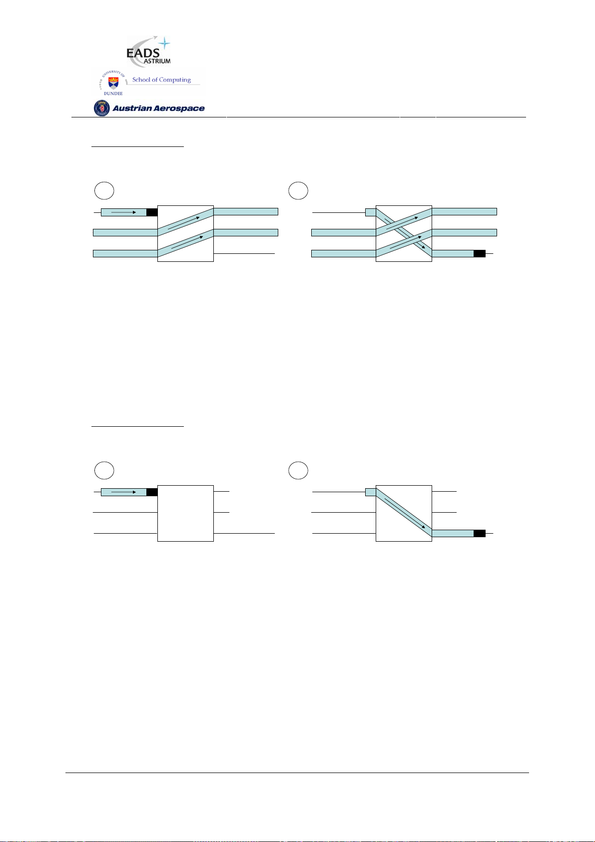
Addres s 76 –Routing table entr y
Header Deletion disable d
Port 4
Port 5
Port 6
1 2
SpW-10X
SpaceWire Router
User Manual
Ref.:
Issue:
Date:
UoD_SpW-10X_
UserManual
3.4
th
July 2008
11
76
1
2
3
Group adaptive routing pac ket with addre ss 76 arrives at port 1
Ports 4 and 5 are busy routing packet data from ports 2 and 3
4
5
R1
6
Routing logic assigns por ts 6 to pac ket at port 1
1
2
3
4
5
R1
6
76
Figure 8-11 Group adaptive routing when other ports busy
8.3.3.3 Group adaptive routing when ports not ready
A similar arrangement to that of section 8.3.3.2 is shown in Figure 8-12. In this scenario, two of the
output ports which address 76 can use are not ready for use (i.e. the links are not running). The
packet is routed to output port 6 since it is running and not being used to route another packet.
Addres s 76 –Routing table entr y
Header Deletion disable d
Port 4
Port 5
Port 6
1 2
76
1
4
X
1
4
X
2
3
Group adaptive routing pac ket with addre ss 76 arrives at port 1
Ports 4 and 5 are not ready to accept packet data
X
6
5
R1
2
3
Routing logic assigns por ts 6 to pac ket at port 1
5
R1
X
6
76
Figure 8-12 Group adaptive routing when ports not ready
Note: if the Start on Request mode is enabled, the output ports in the group that are not ready will
attempt to make a connection. The packet will be routed to the output port in the group that is ready
first.
8.3.4 Loop-back with Self-Addressing
The Enable Self-Addressing bit in the router control register determines if the router is to support loop-
back connections. Loop-back connections can be useful for debugging or ping operations where a
packet is “bounced” of the router and returned to the source. If the Enable Self-Addressing bit is clear
Preliminary
93
Page 94
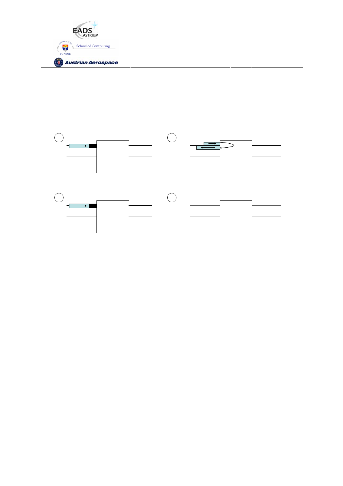
SpW-10X
SpaceWire Router
User Manual
Ref.:
Issue:
Date:
UoD_SpW-10X_
UserManual
3.4
th
July 2008
11
then a packet that that is addressed to go out of the same port that it arrived on will be discarded and
a packet address error recorded.
Command reply packets which are returned through the same port they arrived on are not affected by
the value of the Enable Self-Addressing bit.
Figure 8-13 shows the Enable Self-Addressing mode when enabled and when disabled.
1 2
1
1
4
1
4
R1
2
3
Packet arrives at port 1 with address 1
“Address-sel f mode” is enabled
1 2
1
1
2
3
Packet arrives at port 1 with address 1
“Address-sel f” mode is disabled
5
6
4
R1
5
6
Figure 8-13 Packet Self-Addressing mode
R1
2
3
Packet is routed to por t 1 and pac ket data ret urns on link one
1
2
3
Packet is discarded by the routing control logic
5
6
4
R1
5
6
Preliminary
94
Page 95

SpW-10X
SpaceWire Router
User Manual
Ref.:
Issue:
Date:
UoD_SpW-10X_
UserManual
3.4
th
July 2008
11
8.3.5 Packet Blocking
The Time-Out Enable bit (bit 0) of the router control register enables the watchdog timers on the ports.
When this bit is set and the watchdog timers are enabled the router is in “Watchdog Timer” mode.
When it is clear and the watchdog timers are disable then the router is in the “Blocking Allowed”mode.
In Blocking Allowed mode packets wait indefinitely on other packets to complete. An exception to this
is when an output port that a packet is to be routed to is a SpaceWire port and that port is not started.
In this case the packet waits as long as the timeout period and is then discarded if the output port has
not started. If group adaptive routing is being used and at least one of the destination ports is running
then the packet will wait indefinitely for that output port to become free or another one in the group to
start.
In Watchdog Timer mode watchdog timers on the ports are used to clear packets from the network if
they become blocked, either while being routed or while waiting on a port which is not granted to any
other port. The watchdog timers are restarted every time a data character is transferred. They are
stopped after an EOP and started again on the first data character of a packet. In this way the time to
transfer a complete packet is not checked but instead the watchdog timers check if a packet has
blocked (i.e. no data transfers).
A blocked packet is spilt by terminating the packet at the router output port with an EEP and spilling
the remainder of the packet to be transmitted up to and including the EOP at the router input port. If
the router output port is blocked (full) and cannot accept data then the EEP is added after the port is
unblocked.
WARNING
Blocking Allowed mode is not recommended and should be used with caution.
When Blocking Allowed mode is used (Watchdog timers disabled) then it is important that provision is
made for a network manager to detect blocking situations and to reset the nodes or routers causing
the problem.
The various ways in which an input port can become blocked and the resulting actions taken by the
router are considered in the following sub-sections:
8.3.5.1 Blocked destination
In a blocked destination scenario data cannot be transmitted to the destination port because there is
no more transmit credit (no more FCTs received) in a SpaceWire port or an external port output FIFO
has become full. Since the destination node is blocked the packet data is left strung out across the
SpaceWire network from the packet source to the blockage. In this situation the tail of the packet is
distributed across multiple routers and other network paths can become blocked waiting on the
original blocked packet to complete.
Preliminary
95
Page 96

SpW-10X
SpaceWire Router
User Manual
Ref.:
Issue:
Date:
UoD_SpW-10X_
UserManual
3.4
th
July 2008
11
In blocking allowed mode the network path is blocked until the destination node starts to accept data
again. Packets waiting to use the network path will wait indefinitely.
In watchdog timer mode the router will timeout and the network path will be cleared so other packets
can use the path.
Blocking Allowed Mode
What happens when Blocking Allowed mode is being used and a destination node becomes blocked
is illustrated in Figure 8-14 to Figure 8-16. In this example two routing switches, R1 and R2, are
connected to form a network and only SpaceWire ports 1 to 6 are shown for clarity.
a) A packet arrives at port 3 of routing switch R1 destined for port 4 and then port 5 of R2 (as
shown by the path address 4, 5 at the head of the packet.
R1
4
5
6
(a)
14
2
3
R2
5
6
1
2
3
45
Figure 8-14 Destination Node Blocked (a)
b) The packet is routed towards its destination but during packet transfer the destination stalls
and does not accept any more data. The network path is blocked and the packet waiting at R1
port 2 is also blocked
1
4
14
2
44
3
R1
5
6
(b)
2
3
R2
5
6
Figure 8-15 Destination Node Blocked (b)
c) The path between routing switch R1 port 4 and routing switch R2 port 1 is now blocked. While
the first packet is routed another packet arrives at port 2 on router R1 with destination port 4
on router R1 and destination port 4 on router R2. The packet must wait as the ports are
currently busy and can only be routed if the downstream node starts receiving data again.
Preliminary
96
Page 97

SpW-10X
SpaceWire Router
User Manual
Ref.:
Issue:
Date:
UoD_SpW-10X_
UserManual
3.4
th
July 2008
11
R1
4
5
6
(c)
14
2
3
R2
5
6
1
2
44
3
Figure 8-16 Destination Node Blocked (c)
Watchdog timer mode
What happens when the routers are in Watchdog Timer mode and a destination becomes blocked is
illustrated in Figure 8-17to Figure 8-20. Only SpaceWire ports 1 to 6 are shown for clarity.
a) A packet arrives at port 3 of routing switch R1 destined for port 4 and then port 5 of R2
1
2
44
3
45
R1
4
5
6
(a)
14
2
3
R2
5
6
Figure 8-17 Destination Node Blocked: Watchdog Mode (a)
b) The packet is routed towards its destination but during packet transfer the destination stalls
and does not accept further data. The network path is blocked and the packet waiting at R1
port 2 is also blocked
R1
4
5
6
(b)
14
2
3
R2
5
6
1
2
44
3
Figure 8-18 Destination Node Blocked: Watchdog Mode (b)
c) At routing switches R1 and R2 the watchdog timers detect the packet has blocked for the
specified timeout period. The packet is then discarded by the routers by spilling the data at the
input port and appending an EEP to the data at the output ports. Once the packet has been
removed from the network an EEP is ready to be appended to routing switch R2 port 5 when
buffer space is available and the network path between routing switch R1 port 4 and routing
switch R2 port 1 is available.
Preliminary
97
Page 98

SpW-10X
SpaceWire Router
User Manual
Ref.:
Issue:
Date:
UoD_SpW-10X_
UserManual
3.4
th
July 2008
11
1
2
44
3
4
5
R1 R2
6
(c)
14
E
E
2
3
P
5
6
Figure 8-19 Destination Node Blocked: Watchdog Mode (c)
d) The packet waiting at routing switch R1 port 2 is routed and the network blockage is cleared.
Routing switch R2 port 5 still has data waiting to be sent followed by the end of packet,
therefore packets routed to port 5 will again cause a blockage which will be cleared again in
the same manner until the fault is detected by a higher level protocol.
1
2
3
R1
4
5
6
(d).
14
2
3
R2
5
6
Figure 8-20 Destination Node Blocked: Watchdog Mode (d)
8.3.5.2 Stalled source
A source of a SpaceWire packet can stall for some reason and stop sending data part way through
sending a packet. A router will see this situation as an input port which has stalled, no longer sending
data part way through sending a packet although the SpaceWire link is still running. This situation can
occur due to an error in the network or in the node that was providing data.
In blocking allowed mode the network path will be blocked until the source node supplies the end of
packet. Other packets waiting to use the network path will wait indefinitely.
In watchdog timer mode the routers will timeout and the network path will be cleared so other packets
can use the path.
Blocking Allowed
The sequence of events when a source is stalled and Blocking Allowed mode is being used is
illustrated in Figure 8-21 to Figure 8-24.
a) A packet arrives at routing switch port 3 with destination address 4, 5 which will route to
routing switch R2 port 5. Another packet arrives which is destined for routing switch R2 port 4.
Preliminary
98
Page 99

SpW-10X
(b)
(d)
SpaceWire Router
User Manual
Ref.:
Issue:
Date:
UoD_SpW-10X_
UserManual
3.4
th
July 2008
11
1
2
44
3
45
4
R1
5
6
(a)
14
R2
2
3
5
6
Figure 8-21 Source Node Stalled (a)
b) The packet from routing switch R1 port 3 is routed towards its destination but during packet
transfer the source node stalls and does not supply any further data or the end of packet.
1
2
44
3
4
R1
5
6
14
R2
2
3
5
6
Figure 8-22 Source Node Stalled (b)
c) The packet is blocked and the packet waiting at routing switch R1 port 2 cannot be routed.
1
4
14
R1
2
44
3
5
6
(c)
R2
2
3
5
6
Figure 8-23 Source Node Stalled (c)
d) After an undetermined time the source node supplies the remaining data and end of packet
and the packet waiting at R1-2 can be routed.
1
2
3
4
R1
5
6
14
R2
2
3
5
6
Figure 8-24 Source Node Stalled (d)
Watchdog Timer Mode
What happens when a source stalls and Watchdog Timer mode is being used is illustrated in Figure
8-25 to Figure 8-28:
a) A packet arrives at routing switch port 3 with destination address 4, 5 which will route to
routing switch R2 port 5. Another packet arrives which is destined for routing switch R2 port 4.
Preliminary
99
Page 100

SpW-10X
(c)
SpaceWire Router
User Manual
Ref.:
Issue:
Date:
UoD_SpW-10X_
UserManual
3.4
th
July 2008
11
1
2
44
3
45
R1
4
5
6
(a)
14
2
3
R2
5
6
Figure 8-25 Source Node Stalled: Watchdog Mode (a)
b) The packet from routing switch R1 port 3 is routed towards its destination but during packet
transfer the source node stalls and does not supply any more data or the end of packet.
1
2
44
3
R1
4
5
6
(b)
14
2
3
R2
5
6
Figure 8-26 Source Node Stalled: Watchdog Mode (b)
c) The packet is blocked and the packet waiting at routing switch R1 port 2 cannot be routed.
The watchdog timers in routing switches R1 and R2 detect the packet has become blocked
and spills data from the input port and appends an error end of packet to the output port. This
causes the network path from routing switch R1 port 4 to routing switch R2 port 1 to be
cleared and the next packet can be routed.
1
2
44
3
R1
4
5
6
Figure 8-27 Source Node Stalled: Watchdog Mode (c)
d) The packet waiting at R1 port 2 can now be routed.
1
2
3
R1
4
5
6
(d)
Figure 8-28 Source Node Stalled: Watchdog Mode (d)
14
E
E
P
2
3
14
2
3
R2
R2
5
6
5
6
Preliminary
100
 Loading...