

Atlas IED FAP33T-WEGS, FAP33T-WEGR, FAP33T-BEGS, FAP33T-BEGR, FAP33T Installation Guide
...
1/2
FAP33T Strategy III Series
Install Sheet
Drop Tile Ceiling Installation
1. Remove 2' x 2' or 2' x 4' tile.
2. Align adjustable dual rail & C-ring assembly on rear of tile in desired position.
5
3. Using the template provided, mark the 7-
4. Affix C-ring assembly to rails using screws provided and position assembly on rear of ceiling tile. Replace tile in grid. Ensure formed ends of tile
bridge rails extend to T-bar tile support rails.
5. Bring service loop from rear of tile, through the tile bridge / C-ring to the access panel located on top of enclosure. Terminate the service loop to
Phoenix style connector provided (please note polarity).
6. Insert enclosure through front of tile then follow these steps for the 3 “T-Handle” / dog legs that comprise the Safety First Mounting System.
A. Disengage first “T-Handle” from baffle.
B. Pull “T-Handle” down carefully in a smooth continuous motion until the dog leg engages the C-ring.
C. Carefully push the “T-Handle” upwards until you can feel it disengage from the dog leg.
D. Rotate the “T-Handle” 90 degrees clockwise and align the locking tab with the horizontal slot in the speaker baffle.
E. Push the “T-Handle” into the slot until it clicks, indicating locked position.
F. Repeat steps A - E above for the remaining 2 “T-Handles” / dog legs.
7. Adjust front mounted switch to desired power tap setting or 8Ω / 6Ω * (See important note regarding 8Ω / 6Ω operation).
8. Install press-fit grille into front bezel ring. Push baffle upwards until baffle is flush with bezel ring.
9. For safety and seismic considerations a suspension ring is integrated into the input panel section of unit. Atlas Sound strongly suggests that a
support wire be installed from this support point to a suitable anchor point above ceiling grid. In drop tile applications, this wire can usually be
installed from an adjacent tile access near speaker location.
/8" cut out circle with marker and cut hole.
Dry Wall (“Hard Deck”) Installation
1. Using the template provided, mark the 7-5/8" cut out circle with marker and cut hole.
2. Place tile bridge rails and C-ring through hole. Use V-shaped edge of C-ring to align tile bridge assembly above ceiling (alignment screws provided
are not required for this type of installation)
3. Bring service loop from rear of ceiling, through the Tile Bridge / C-ring to access panel located on the side of the enclosure. Terminate service loop
to Phoenix style connector provided (please note polarity).
4. Insert enclosure through front of tile then follow these steps for the 3 “T-Handle” / dog legs that comprise the Safety First Mounting System.
A. Disengage first “T-Handle” from baffle.
B. Pull “T-Handle” down carefully in a smooth continuous motion until the dog leg engages the C-ring.
C. Carefully push the “T-Handle” upwards until you can feel it disengage from the dog leg.
D. Rotate the “T-Handle” 90 degrees clockwise and align the locking tab with the horizontal slot in the speaker baffle.
E. Push the “T-Handle” into the slot until it clicks, indicating locked position.
F. Repeat steps A - E above for the remaining 2 “T-Handles” / dog legs.
5. Adjust front mounted switch to desired power tap setting or 8Ω/6Ω * (See important note regarding 8Ω/6Ω operation)
6. Install press-fit grille into front bezel ring. Push baffle upwards until baffle is flush with bezel ring.
7. For safety and seismic considerations a suspension ring is integrated into the input panel section of unit. Atlas Sound strongly suggests that a
support wire be installed from this support point to a suitable anchor point above ceiling grid.
©2016 Atlas Sound L.P. All Rights Reserved. Atlas Sound is a trademark of Atlas Sound L.P. All other trademarks are the property of their respective owners. All specs are subject to change without notice. ATS005237 RevC 3/16
1601 JACK MCKAY BLVD.
ENNIS, TEXAS 75119 U.S.A.
TELEPHONE: (800) 876-3333
FAX (800) 765-3435
AtlasSound.com
*DO NOT USE 8Ω / 6Ω SETTING WITH 70.7V / 100V SYSTEMS!
FAP33T
Full Range
16W @ 70.7V
Ceiling Material up to 1-1/2"
Auxiliary Suspension Point
Tile Bridge
Ceiling Material up to 2"
Tile Bridge
Auxiliary Suspension Point
Dogleg In Normal Position Dogleg In Inverted Position
FAP33T
Full Range
16W @ 70.7V
Ceiling Material up to 2"
Tile Bridge
Auxiliary Suspension Point
Dogleg In Inverted Position
*DO NOT OVERPOWER IN 8Ω CONFIGURATION!
AMPLIFIER OUTPUT SHOULD NOT EXCEED 25 W RMS @ 6Ω PER SPEAKER.
Frequency Response: 400 - 4kHz (Fire Signaling), 100 - 10kHz (General Signaling)
Recommended Cable Type: Solid / Stranded Copper AWG 18 - 12 (or equivalent)
5
Tile / Drywall Cutout Circle: 7-
/8"
Paint Shield Cutout Circle: 7"
Removing speaker from ceiling:
1. While holding the speaker in place; pull down the “T-Handle” and turn to reveal the small hole adjacent to the locking slot.
2. Insert the provided release tool into the hole and move the tool back and forth until you can hear the dog leg release.
3. Repeat steps 1 and 2 for the 2 remaining doglegs
2/2
Note:
UL recognized conduit clamp must be used for conduit connections.
Cable connection cavity is not intended to be used as a junction box.
Not intended for use in DC Supervisory systems.
Typical wiring method shall be in accordance with the applicable section of the National Electrical Code, ANSI/NFPA 70 or ANSI/NFPA 72
and CSA C22.1, Canadian Electrical Code, Part I, Safety Standard for Electrical Installations.
Changing factory finish is not recommended in Fire Signaling applications.
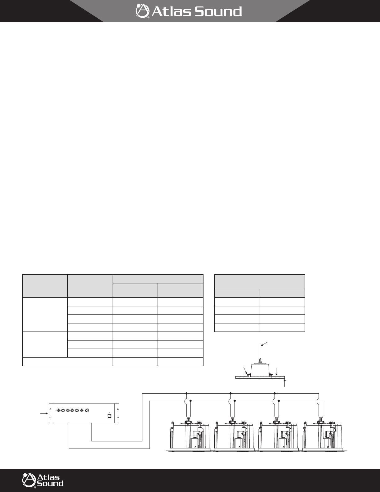
Voltage
(Vrms)
Power Tap (W)
2 83.2 80.9
70.7
4 85.8 82.9
8 88.2 85.7
16 90.0 87.0
100
4 85.8 83.6
8 88.2 86.4
16 90.2 87.5
6Ω Direct Input 88.8 90.6
Typical Parallel Hookup of Full Range 70.7V/100V Speakers
Amplifier
Typical 120 Watt 70.7V Output
Tap Power Total: 60 Watts
OSPL (dBA) at 10 ft
UL1480
Reverberant
ULC-S541
Anechoic
Horizontal and Vertical
Dispersion Characteristics
Axis Angle dBA
0 0
± 30 ° -3
± 60 ° -6
± 90 ° -9.4
Auxiliary Suspension Point
Dogleg In Normal Position
Ceiling Material up to 1-1/2"
Tile Bridge
3 4 5 6 master
Input
©2016 Atlas Sound L.P. All Rights Reserved. Atlas Sound is a trademark of Atlas Sound L.P. All other trademarks are the property of their respective owners. All specs are subject to change without notice. ATS005237 RevC 3/16
1 2
1601 JACK MCKAY BLVD.
ENNIS, TEXAS 75119 U.S.A.
power
power
+
–
+
–
FAP33T
Full Range
16W @ 70.7V
TELEPHONE: (800) 876-3333
FAX (800) 765-3435
+
FAP33T
Full Range
16W @ 70.7V
–
+
–
FAP33T
Full Range
16W @ 70.7V
+
–
FAP33T
Full Range
16W @ 70.7V
AtlasSound.com
 Loading...