


Atmosphere™
Next-Gen Expandable Zone DSP Controller
User Manual
1601 JACK MCKAY BLVD. |
TELEPHONE: (800) 876-3333 |
AtlasIED.com |
|
ENNIS, TEXAS 75119 U.S.A. |
SUPPORT@ATLASIED.COM |
||
|
|||
|
|
|

Atmosphere |
|
|
User Manual |
|
|
Table of Contents |
|
|
Important Safety Instructions...................................................................................................................................................................................... |
|
4 |
Introduction................................................................................................................................................................................................................... |
|
5 |
Key Features and Applications.................................................................................................................................................................................... |
|
5 |
Package Contents......................................................................................................................................................................................................... |
|
6 |
Rack Installation Guide................................................................................................................................................................................................. |
|
7 |
Hardware Overview...................................................................................................................................................................................................... |
|
8 |
AZM4 & AZM8 Front Panel .................................................................................................................................................................................... |
|
8 |
AZM8 Back Panel.................................................................................................................................................................................................... |
|
9 |
AZM4 Back Panel.................................................................................................................................................................................................... |
|
9 |
Connections................................................................................................................................................................................................................. |
|
11 |
Cabling.................................................................................................................................................................................................................. |
|
11 |
Network Connection Overview................................................................................................................................................................................. |
|
12 |
Connecting Network Devices for Configuration................................................................................................................................................... |
|
12 |
Method 1 - Ethernet Wired Connection........................................................................................................................................................ |
|
12 |
Method 2 - WiFi Connection......................................................................................................................................................................... |
|
12 |
Method 3 - Access Point Connection........................................................................................................................................................... |
|
13 |
Software Overview..................................................................................................................................................................................................... |
|
13 |
Dashboard ............................................................................................................................................................................................................ |
|
13 |
Features........................................................................................................................................................................................................ |
|
13 |
Inputs Page........................................................................................................................................................................................................... |
|
14 |
Mic/Line........................................................................................................................................................................................................ |
|
14 |
General Settings Page............................................................................................................................................................................ |
|
15 |
Gate........................................................................................................................................................................................................ |
|
15 |
De-Esser................................................................................................................................................................................................. |
|
16 |
Compressor............................................................................................................................................................................................ |
|
17 |
Equalizer................................................................................................................................................................................................. |
|
18 |
Auto-Gain Control................................................................................................................................................................................... |
|
19 |
RCA Inputs.................................................................................................................................................................................................... |
|
20 |
General Settings Page............................................................................................................................................................................ |
|
20 |
Audio Wall Plate Accessories....................................................................................................................................................................... |
|
21 |
Audio Wall Plate Inputs................................................................................................................................................................................. |
|
21 |
General Settings for A-XLR Page............................................................................................................................................................ |
|
22 |
General Settings for A-RCA Page........................................................................................................................................................... |
|
23 |
General Settings for A-BT Page.............................................................................................................................................................. |
|
24 |
How to Pair the A-BT Wall Plate............................................................................................................................................................. |
|
24 |
Virtual Mix Inputs.......................................................................................................................................................................................... |
|
25 |
Input Mix Page....................................................................................................................................................................................... |
|
25 |
Signal Generator Input.......................................................................................................................................................................................... |
|
26 |
Zone Outputs........................................................................................................................................................................................................ |
|
26 |
General Settings Page.................................................................................................................................................................................. |
|
27 |
Equalizer........................................................................................................................................................................................................ |
|
28 |
Ambient Noise Compensation – ANC........................................................................................................................................................... |
|
29 |
ANC – Auto Mode.................................................................................................................................................................................. |
|
30 |
Ambient Noise Sensor - X-ANS .................................................................................................................................................................... |
|
30 |
Ambient Noise Sensor Placement................................................................................................................................................................ |
|
31 |
Rule-1..................................................................................................................................................................................................... |
|
31 |
Rule-2 .................................................................................................................................................................................................... |
|
32 |
Rule-3..................................................................................................................................................................................................... |
|
32 |
Rule-4..................................................................................................................................................................................................... |
|
33 |
Rule-5..................................................................................................................................................................................................... |
|
33 |
Limiter........................................................................................................................................................................................................... |
|
34 |
Message Player Overview ......................................................................................................................................................................................... |
|
35 |
Messages............................................................................................................................................................................................................. |
|
35 |
Audio Files............................................................................................................................................................................................................ |
|
36 |
Priority................................................................................................................................................................................................................... |
|
36 |
1601 JACK MCKAY BLVD. |
TELEPHONE: (800) 876-3333 |
|
|
|
AtlasIED.com |
ENNIS, TEXAS 75119 U.S.A. |
SUPPORT@ATLASIED.COM |
|
– 2 –

|
Atmosphere |
|
|
User Manual |
|
GPIO Overview ........................................................................................................................................................................................................... |
37 |
|
GPIO Inputs.......................................................................................................................................................................................................... |
37 |
|
Setting Up a GPIO to Recall a Scene and/or Play a Message....................................................................................................................... |
37 |
|
GPIO Outputs (GPO’s).......................................................................................................................................................................................... |
38 |
|
High Priority.......................................................................................................................................................................................................... |
39 |
|
Setting Up a High Priority GPIO to Play an Alert Message........................................................................................................................... |
39 |
|
Scenes Overview......................................................................................................................................................................................................... |
40 |
|
Setting Up a Scene............................................................................................................................................................................................... |
40 |
|
Accessories Overview................................................................................................................................................................................................. |
41 |
|
Control Accessories ............................................................................................................................................................................................. |
41 |
|
Setting Up a Virtual Wall Controller ...................................................................................................................................................................... |
43 |
|
Virtual Controller General Settings................................................................................................................................................................ |
43 |
|
Zones & Sources........................................................................................................................................................................................... |
43 |
|
Scenes.......................................................................................................................................................................................................... |
44 |
|
Messages..................................................................................................................................................................................................... |
44 |
|
Print-Assemble-Place-Scan........................................................................................................................................................................... |
45 |
|
Setting Up Accessory Port Wall Controllers.......................................................................................................................................................... |
46 |
|
C-ZSV General Settings......................................................................................................................................................................................... |
46 |
|
Zones, Source, and Volume Settings............................................................................................................................................................ |
47 |
|
Scenes.......................................................................................................................................................................................................... |
48 |
|
Messages..................................................................................................................................................................................................... |
48 |
|
Screen Settings............................................................................................................................................................................................. |
49 |
|
Light Ring Settings........................................................................................................................................................................................ |
49 |
|
C-V General Settings............................................................................................................................................................................................. |
50 |
|
Zones Volume............................................................................................................................................................................................... |
51 |
|
Light Ring...................................................................................................................................................................................................... |
51 |
|
X-ANS General Settings........................................................................................................................................................................................ |
52 |
|
Accessories Connection Rules................................................................................................................................................................................... |
52 |
|
Scheduler..................................................................................................................................................................................................................... |
|
54 |
Steps to Create an Event...................................................................................................................................................................................... |
55 |
|
Diagrams...................................................................................................................................................................................................................... |
|
54 |
Connection Diagram............................................................................................................................................................................................. |
55 |
|
Block Diagram ...................................................................................................................................................................................................... |
55 |
|
Inputs and Outputs....................................................................................................................................................................................... |
55 |
|
Settings Page Overview............................................................................................................................................................................................. |
56 |
|
1) |
Configurations........................................................................................................................................................................................ |
56 |
2) |
Network.................................................................................................................................................................................................. |
57 |
3) |
Firmware................................................................................................................................................................................................ |
57 |
4) |
Device Settings...................................................................................................................................................................................... |
58 |
5) |
Clock....................................................................................................................................................................................................... |
58 |
6) |
Event Log............................................................................................................................................................................................... |
59 |
7) |
Licenses................................................................................................................................................................................................. |
59 |
8) |
User Account ......................................................................................................................................................................................... |
59 |
9) |
Project Settings...................................................................................................................................................................................... |
60 |
10) Theme ................................................................................................................................................................................................... |
60 |
|
Front Panel Display Menu Tree.................................................................................................................................................................................. |
61 |
|
Specifications.............................................................................................................................................................................................................. |
62 |
|
Mechanical Line Drawings with Dimensions........................................................................................................................................................... |
65 |
|
AZM4, AZM8, Accessories................................................................................................................................................................................... |
65 |
|
Regulatory Information: AZM4 / AZM8 / A-BT........................................................................................................................................................ |
68 |
|
Compliance Certs/FCC Statement........................................................................................................................................................................ |
69 |
|
Limited Warranty........................................................................................................................................................................................................ |
70 |
|
Customer Service........................................................................................................................................................................................................ |
70 |
|
1601 JACK MCKAY BLVD. |
TELEPHONE: (800) 876-3333 |
AtlasIED.com |
|
ENNIS, TEXAS 75119 U.S.A. |
SUPPORT@ATLASIED.COM |
||
|
|||
|
|
|
– 3 –
Atmosphere
User Manual
Important Safety Instructions
13. Only use attachments / accessories specified by the manufacturer.
CAUTION
RISK OF ELECTRIC SHOCK
DO NOT OPEN
RISQUE DE CHOC ELECTRIQUE
NE PAS OUVRIR
TO REDUCE THE RISK OF ELECTRIC SHOCK
DO NOT REMOVE COVER (OR BACK)
NO USER SERVICEABLE PARTS INSIDE
REFER SERVICING TO QUALIFIED PERSONNEL
Labeling on products and the Installation Instructions & User Manual may use safety related graphical symbols as shown below to note safety requirements.
 Lightning Bolt: lightning flash with arrowhead symbol, within an equilateral triangle, WARNING symbol, is intended to alert the user to the presence of un-insulated dangerous voltage within the product’s enclosure that may be sufficient in magnitude to constitute a risk of electric shock to persons or domestic animals.
 Exclamation Point:The exclamation point within an equilateral triangle, CAUTION symbol, is intended to alert the user to the presence of important operating and maintenance (servicing) instructions, or a hazard that can damage equipment.
 Do not proceed beyond a WARNING or CAUTION notice until you have understood the hazardous condition and have taken appropriate steps.
 Ne continuez pas avant d’avoir pris connaissance du danger et prendre les mesures appropriées.
1.Read these instructions.
2.Keep these instructions.
3.Heed all warnings.
4.Follow all instructions.
5.Do not use this device near water.
6.Clean only with dry cloth.
7.Do not block any ventilation openings. Install in accordance with the manufacturer’s instructions.
8.Do not install near any heat sources such as radiators, heat registers, stoves, or other device that produce heat.
9.This product is equipped with a three-wire grounding-type plug, a plug having a third (grounding) pin. This plug will only fit into a ground-
ing-type power outlet. This is a safety feature. If you are unable to insert the plug into the outlet, contact your electrician to replace your obsolete outlet. Do not defeat the safety purpose of the grounding-type plug.
10.To completely disconnect this equipment from the mains, disconnect the power supply cord plug from the receptacle.
11.The mains plug of the power supply cord shall remain readily operable.
12.Protect the power cord from being walked on or pinched particularly at plugs, convenience receptacles, and the point where they exit from the device.
14.Use only with the cart, stand, tripod, bracket, or table specified by the manufacturer, or sold with the device. When a cart is used, use caution when moving the cart / device combination to avoid injury from tip-over.
15.Unplug this device during lightning storms or when unused for long periods of time.
16.Refer all servicing to qualified service personnel. Servicing is required when the device has been damaged in any way, such as power-supply cord or plug is damaged, liquid has been spilled, or objects have fallen into the device, the device has been exposed to rain or moisture, does not operate normally, or has been dropped.
WARNING: To reduce the risk of fire or electric shock, do not expose this apparatus to rain, moisture, dripping, splashing, or place objects filled with liquids on the equipment.
AVERTISSEMENT: Afin de réduire le risque d’incendie ou de choc électrique, n’exposez pas cet appareil à la pluie, à l’humidité, à l’égouttement, aux éclaboussures, et ne posez pas des objets remplis
de liquide sur l’appareil
WARNING: If apparatus is equipped with Class I grounding plugs for safety purposes, it must be connected to MAINS that employ a protective earth ground connection.
AVERTISSEMENT: si l’appareil est équipé de prises de terre classe I, pour des raisons de sécurité, il doit être branché sur un réseau ayant une prise de terre de protection.
WARNING: The MAINS plug on this device may be used as the DISCONNECT DEVICE for MAINS power and must remain readily operable.
AVERTISSEMENT: La prise principale de cet appareil peut être utilisé comme DISPOSITIF de DECONNEXION du courant principal et doit rester facilement accessible.
WARNING: Installation and maintenance of AtlasIED equipment is to be made by trained / qualified personnel and must conform to all applicable local codes.
AVERTISSEMENT: l’installation et la maintenance des équipements AtlasIED doit être faite par du personnel formé / qualifié et doivent être conformes à toutes les réglementations locales en vigueur.
WARNING: If unit contains a lithium battery, there is a danger of explosion. Replace only with the same or equivalent type.
AVERTISSEMENT: Si l’unité contient une pile au lithium, il y a un danger d’explosion. Remplacez-la uniquement avec un modèle identique ou équivalent.
WEEE NOTICE: This appliance is labeled in accordance with European Directive 2012/19/EU concerning waste of electrical and electronic equipment (WEEE). This label indicates that this product should not be disposed of with household waste. It should be deposited at an appropriate facility to enable recovery and recycling.
1601 JACK MCKAY BLVD. |
TELEPHONE: (800) 876-3333 |
AtlasIED.com |
|
ENNIS, TEXAS 75119 U.S.A. |
SUPPORT@ATLASIED.COM |
||
|
|||
|
|
|
– 4 –

Atmosphere
User Manual
Introduction
Thank you for choosing AtlasIED and the Atmosphere line of signal processors for your project. The Atmosphere family of products are designed to meet the highest standards for design, quality, and value that our customers have come to expect from AtlasIED. The flexibility and breadth of available accessories that the Atmosphere ecosystem offers is unmatched in the industry. We believe you will find this new platform highly flexible to address a variety of applications and refreshingly simple to deploy. With a new approach to solving real world customer problems, the Atmosphere line of products sets the new standard for the fixed architecture zone-based processing market. From all of us at AtlasIED, we once again thank you for your purchase and look forward to working with you in the future.
Inputs and Outputs
The AZM4 features a 6 input / 4 output configuration with 4 mic/line and 2 RCA stereo summed inputs and 4 output zones. In addition, 2 RJ45 bus ports each allow for 1 audio wall plate accessory, A-XLR, A-RCA or A-BT, bringing the total input count to 8 by 4 out.
The AZM8 features a 10 input / 8 output configuration with 8 mic/line and 4 RCA stereo summed inputs and 8 output zones. In addition, 4 RJ45 bus ports each allow for 1 audio wall plate accessory, A-XLR, A-RCA or A-BT, bringing the total input count to 14 by 8 out.
Flexible Assortment of Accessories
Six plug and play smart Wall Plate accessories, unmatched in the industry, expand the AZM capabilities and allow for future scalability. Accessories include 3 x Audio Inputs; balanced Mic / Line XLR, dual RCA stereo summed with 3.5mm, and Bluetooth® audio wall plate inputs, 2 x Controllers; Volume Controls, Volume Controls with Source Select, Scene Recall, and Message Playback, and 1 x Ambient Noise Sensor for Ambient Noise Compensation control. Any control accessory can be daisy chained on a single cable digital bus and assigned to any zone, reducing installation wiring time and complexity.
Configurable Mobile Device Control
With the ability to turn any mobile device into a virtual “App-Less” zone controller by simply scanning a QR Code with a phone or tablet, Atmosphere mobile control is the easiest, most cost-effective way to provide zone control to the customer. Setup the type of control you want on the user’s device, print QR codes directly from the settings page and mount in their respective zone using the X-GEM mounting frame.
Comprehensive Web User Interface with Dashboard
Also included is a user-friendly web-based User Interface (UI) controller with deep dive capabilities to meet the most expansive and highest level of settings criteria. Inputs feature a full suite of DSP with dynamics like Gates, De-Esser, Compressor, EQ and Auto-Gain. Outputs have 6-band EQ, Automatic Noise Compensation, and Limiter, with output speaker presets based on AtlasIED speaker models. Events can be scheduled just like a meeting in a familiar calendar format with a dashboard that displays the upcoming events scheduled. Scenes can be pre-configured and scheduled or triggered by GPI’s. Upload .wav files to the message player library and schedule playback as an event or trigger the message player by including it in a Scene or with one of the GPI ports. Continuous system monitoring is contained within a dashboard overview to simplify oversight of all of the functions.
Key Features
•4 (AZM4) & 8 (AZM8) – Independently Controlled Zone Models
•Web UI – Designed for Optimal Use with Chrome or Safari Web Browsers
•Plug and Play Intelligent Wall Plate Accessories
•Daisy Chain up to 8 Accessories per Port, 2 Ports on AZM-4, 4 Ports on AZM-8
•Adaptive Ambient Noise Sensor Accessory
•Accessory Data + Audio Digital Bus – RJ45-Cat 5e/6 Wire Runs Up to 1000ft
•Input Auto-Gain Audio Control
•Virtual Wall Controllers for Mobile Devices, with QR Code Set-up; No App Required
•Tilter-Filter Room EQ Adjustment Tool
•AtlasIED Speaker Presets
•Intuitive Calendar Format Event Scheduler
•Integrated .wav File Message Player with Scheduler and GPIO
•Printable Dynamic System Diagram
•Simple, Streamlined Workflow for All Skill Levels
Applications
• |
Restaurant-Bars |
• |
Hospitality Suites |
• |
Houses of Worship |
• |
Medical Centers |
• |
Offices/ Lobbies |
• |
Education |
• |
Corporate Centers |
|
|
1601 JACK MCKAY BLVD. |
TELEPHONE: (800) 876-3333 |
AtlasIED.com |
|
ENNIS, TEXAS 75119 U.S.A. |
SUPPORT@ATLASIED.COM |
||
|
|||
|
|
|
– 5 –
Atmosphere
User Manual
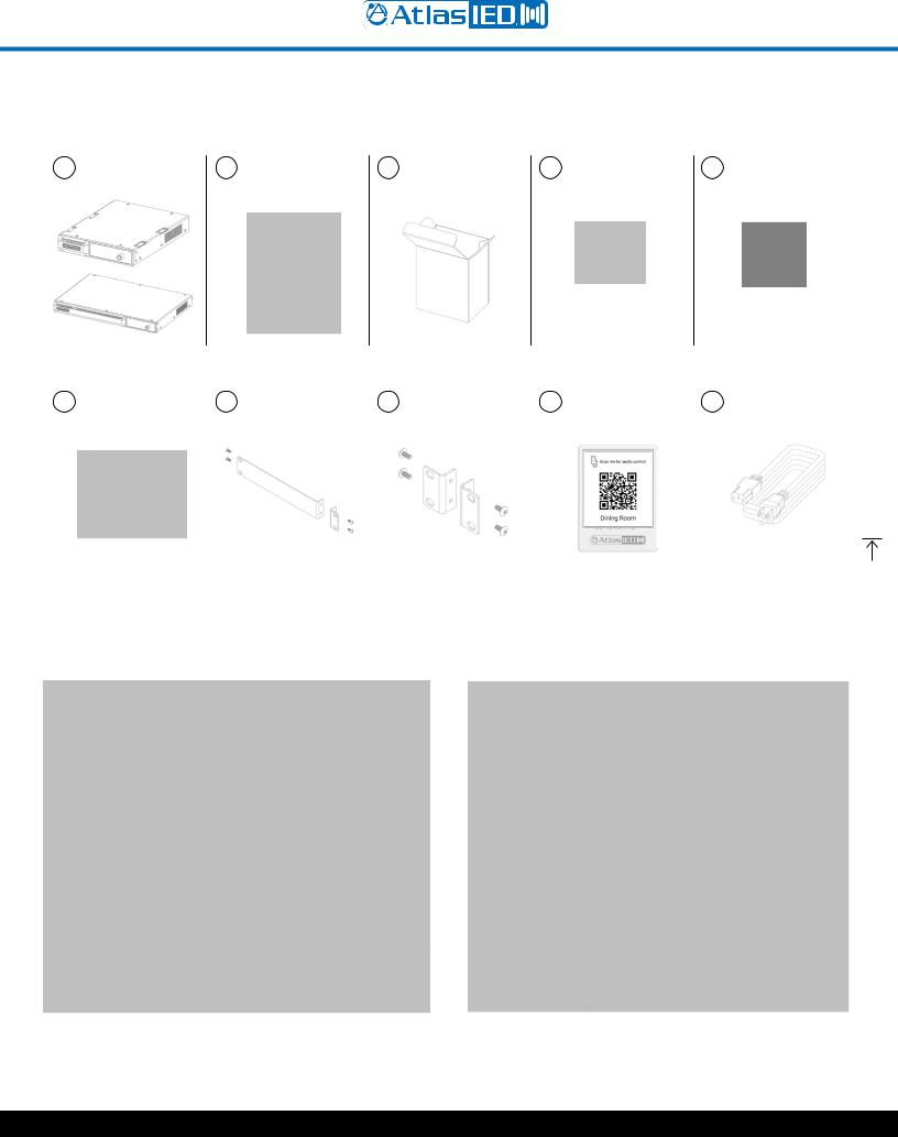
Package Contents
1 AZM4 or AZM8 |
2 Quick Start Guide |
3 Hardware Box |
4 Input Connector |
5 Output Connector |
QTY: 1 |
and Safety Sheet |
QTY: 1 |
AZM4 = QTY: 4 |
AZM4 = QTY: 4 |
|
QTY: 1 |
|
AZM8 = QTY: 6 |
AZM8 = QTY: 6 |
|
|
|
|
|
|
|
|
|
|
|
|
|
|
|
|
|
|
|
|
|
|
|
|
|
6 GPIO Connector |
|
7 AZM4 - 1/2 Rack |
|
8 AZM8 - Rack Ears |
|
9 QR Code Placard |
|
10 IEC Power Cord |
||
|
|
|
|
|
|||||||
|
AZM4 = QTY: 1-12wy |
|
|
Adapter & Screws |
|
& Screws |
|
QTY: 1 |
|
QTY: 1 |
|
|
AZM8 = QTY: 1-12wy |
|
|
|
|
|
|
|
|
|
|
|
|
|
|
|
|
|
|
|
|
|
|
|
|
|
|
|
|
|
|
|
|
|
|
AZM4 |
|
AZM8 |
|
||
|
|
|
1601 JACK MCKAY BLVD. |
TELEPHONE: (800) 876-3333 |
AtlasIED.com |
|
ENNIS, TEXAS 75119 U.S.A. |
SUPPORT@ATLASIED.COM |
||
|
|||
|
|
|
– 6 –
Atmosphere
User Manual
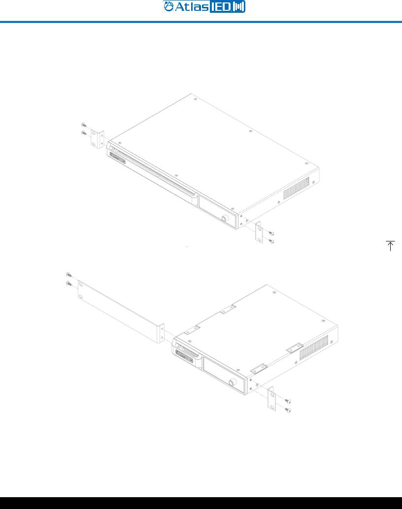
Rack Installation Guide
To rack mount the AZM8, remove included rack ears and fasteners from hardware box and attach to each side.
To rack mount the AZM4, remove included rack ear and ½ rack adapter and fasteners from hardware box and attach to each side.
Note: The AZM4 is a ½-RU device and can be mounted in a side-by-side configuration using the AtlasIED part # PA702-RMK rack kit. It can also be combined with the IP power strip AtlasIED AP-S15HRIP.
Note: When rack mounting the AZM, the fan air flow is from front to back.
1601 JACK MCKAY BLVD. |
TELEPHONE: (800) 876-3333 |
AtlasIED.com |
|
ENNIS, TEXAS 75119 U.S.A. |
SUPPORT@ATLASIED.COM |
||
|
|||
|
|
|
– 7 –

Atmosphere
User Manual
Hardware Overview
AZM4 and AZM8 Front Panel
1.WiFi Enable
Out of the box, the AZM is configured to connect to an existing network via the back panel ethernet port. However, there are two additional methods for connecting to the AZM for configuration, WiFi or Access Point mode, enabled from the front panel menu. If no existing network is available, it is recommended that the onboard WiFi (Access Point mode) be used for initial configuration.
2.Display
The Display is a multi-functional status interrogator and visual activity monitor. It is designed to provide “quick look” verification of selections when in front of the unit and when the UI is not handy. It also allows configuration of network (ethernet, WiFi, and access point) settings.
When first powering the AZM, the Display will show the IP address and the Outputs activity. At the bottom is the Menu > Navigation. Pressing the Navigation control knob will step thru the menu tree in the following order:
•Zone Control – Change sources, volumes, and mute state in any zone. The user can also recall scenes. This has to be configured within the UI before access is given.
•Network – See network status and settings; change mode between access point, WiFi, ethernet; change connection to available networks by signal strength, enter SSID.
•I/O Signals – Select Inputs or Outputs individually and see signal activity.
•Accessories – See Accessories connected to Ports A, B, (AZM4) and A, B, C, or D (AZM8) select and read specific menu of Accessory and find location.
•Faults – Displays “Live” fault events only (“Live” faults also flash light bar red). To clear a Live fault, you must resolve the issue. Example: If two audio accessories (A-XLR, A-RCA, or A-BT) are plugged into the same bus-port, the fault doesn’t go away until unplugging one of them.
•Sensor Data – Read temperature sensor data from I/O; CPU; PSU (power supply unit).
•System Clock – Read Time/Date; refresh NTP.
•Firmware Info – Read current firmware version and last updated Date/Time.
•Lock – Lock/Unlock menu display.
3.Navigation Control & Factory Reset
To cycle through display menus, press knob. To select an option, turn to move cursor & press.
To Factory Reset unit from the front panel, remove power and re-power, then press and hold front panel Navigation Control within 60 seconds. Note: To save Settings prior to Factory Reset, go to Settings, Configurations and Save file to computer for upload after reset. When left undisturbed for 60 secs, the display will return to the default = Outputs.
1601 JACK MCKAY BLVD. |
TELEPHONE: (800) 876-3333 |
AtlasIED.com |
|
ENNIS, TEXAS 75119 U.S.A. |
SUPPORT@ATLASIED.COM |
||
|
|||
|
|
|
– 8 –

Atmosphere
User Manual
4.Light Bar System “State” Indicator
This indicator monitors the current state of the AZM.
•Blue = Unit powered ON and operating properly
•Flash RED = Live Fault is detected
If a Fault is indicated, use the Menu Display to navigate to “Faults”, and evaluate the source of the problem, or go to the UI Dashboard and see Faults for specific cause. Fault is only cleared after resolving the issue. Typical issues that will trigger a Live Fault condition are:
•“Port Wall Plate Overload” – Too many controllers on the port.
•“Port Audio Wall Plate Overload” – Too many Audio Wall Plates on a port.
•“Product Wall Plate Overload” – too many Wall Plates plugged into the AZM.
•“Backwards Audio Error” – Audio Wall Plate connected backwards.
•“Critical Temp Error” – Temperature exceeds maximum acceptable value.
AZM8 Back Panel
AZM4 Back Panel
1.Balanced Mic/Line Inputs
Inputs 1-4 (AZM4) and 1-6 (AZM8) accept balanced input signals via the removable 3.5mm Phoenix type connector. For wiring, follow the labeling on the rear of the AZM. For unbalanced signals, connect the (–) and (GND) pins together. Note: DSP configuration and zone assigning are done in the UI. Any Source Input can be assigned to any Zone Output.
2.Summed Line Inputs
Inputs 5-6 (AZM4) and 7-10 (AZM8) accept standard stereo RCA Line level source devices (media players or computers) and are summed to mono internally for assigning to zones.
1601 JACK MCKAY BLVD. |
TELEPHONE: (800) 876-3333 |
AtlasIED.com |
|
ENNIS, TEXAS 75119 U.S.A. |
SUPPORT@ATLASIED.COM |
||
|
|||
|
|
|
– 9 –

Atmosphere
User Manual
3.Balanced Line Outputs
Zone outputs 1-4 (AZM4) or 1-8 (AZM8) are to connect to balanced line inputs, primarily for amplifiers, such as the Atmosphere AZA amplifiers, that power zone speakers.
4.GPIO (General Purpose Input Output Ports)
The 3.5mm 12-way GPIO Euro block contains:
•3 x Common “C” – these are all tied to common and can be used for any terminal wiring.
•6 x (1 - 6) control inputs – configured individually in the UI as CC (Contact Closure) (Normally Open) or 1.5-12Vdc trigger.
The 6 control inputs can:
•Recall scenes
•Trigger message playback
•1 x Terminal “F” High Priority “HP” input function. The High-Priority input can:
•Mute all zones
•Set all zones to a selected source
•Lock and alert accessory controllers
•Play a message one time or on a repeated basis
•2 (GPO-1 & GPO-2) Control Outputs - Voltage triggers individually assignable in GPIO page and configured under Scenes page. The Scenes page includes 4 types of voltage trigger settings that can be configured: Logic H, Logic L, Toggle, and Pulse along with Pulse Time in 50ms increments, a common “C” terminal for output ports 1 & 2 for external equipment interfacing.
5.Accessory Ports
RJ45 (not-Ethernet) bus-ports A & B (AZM4) or A, B, C & D (AZM8) are used for connecting Atmosphere Plug and Play accessories. All accessories are recognized by the UI automatically when plugged in and can be assigned to any zone. Multiple bus-ports are provided to allow more accessories to be used and to make it easier for installers to create cable homeruns.
To guarantee good performance of all connected accessories, follow these rules:
1.Use CAT5e or CAT6 (non-shield) cable to connect accessories to the host processor bus-port.
2.Up to 8 Accessories can be daisy chained from a single port.
3.Up to 16 Accessories can be connected to a single AZM, (AZM4 or AZM8).
4.The maximum cable length from the AZM to the last accessory on the chain is 1000’(305m).
5.One Audio Wall Plate (A-XLR, A-RCA, A-BT) can be used per bus-port. Note: See “Plug and Play Accessories Connection Rules” for more details. Note: A maximum of 8 X-ANS accessories can be used per AZM.
6.Network
Connect to LAN where device is installed. The AZM default IP is set to DHCP and, when terminated to a router with DHCP enabled, will display the IP address on the front panel display.
7.AC Power
AC Power Input – IEC connector, 100-240VAC ~ 50-60 Hz, universal power supply.
1601 JACK MCKAY BLVD. |
TELEPHONE: (800) 876-3333 |
AtlasIED.com |
|
ENNIS, TEXAS 75119 U.S.A. |
SUPPORT@ATLASIED.COM |
||
|
|||
|
|
|
– 10 –

Atmosphere
User Manual
Connections
Cabling
Balanced Inputs & Outputs - Use of 2 conductor w/shield for low level signals of 20-22 gauge is best. Maintain the proper polarity, + to +, – to – and shield to ground. Note: When using an unbalanced source on the 3.5mm Euro Connector, connect the GND to – with a jumper wire. (see unbalanced image in connections guide).
For the RCA inputs, pre-made RCA cables can be purchased from AtlasIED to simplify interconnection to external devices. https://www.atlasied.com/volume-controls-cables-audio-cables-unbalanced-audio
For RJ45 connections, use CAT5e or CAT6 (non-shield) network cable with T-568B or A wiring. Pre-made network cables must be pin-to-pin. Do not use cross-over network cables. Always use best practices while terminating RJ45s to cables, keeping pairs twisted up to the connector. Avoid tight bends and kinks in the wire path. Note: Pre-made cables may be more difficult to fit in back boxes when used with accessory wall plates. See line drawings with dimensions in the back of this manual for depth consideration.
1601 JACK MCKAY BLVD. |
TELEPHONE: (800) 876-3333 |
AtlasIED.com |
|
ENNIS, TEXAS 75119 U.S.A. |
SUPPORT@ATLASIED.COM |
||
|
|||
|
|
|
– 11 –
Atmosphere
User Manual
Network Connection Overview
Connecting Devices to the AZM for Configuration
Out of the box, the AZM is configured to connect to an existing network via the back panel ethernet port. However, there are two additional methods for connecting to the AZM for configuration. If no existing network is available, it is recommended that the onboard WiFi Access Point (Method -#3) be used for initial configuration.
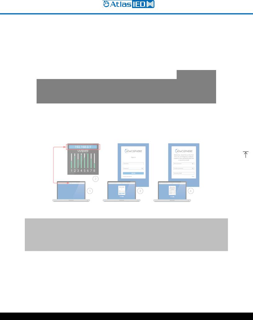
Method-1 - Ethernet Connection (Wired connection)
Connect an RJ45 cable (CAT5e or CAT6) from the AZM ethernet port to an existing network.
Logging in to the AZM:
1.Open web browser on device that is on the same network as the AZM.
2.Navigate to the IP address shown on the front panel of the AZM using the web browser address bar.
3.Login using the username “admin” and password “admin.”
4.After the first login, follow the onscreen instructions to change the default log in credentials.
Method-2 - WiFi Connection (Connect to existing wireless network)
•From the front panel menu enable WiFi mode (Network>WiFi>Change Mode>WiFi, then confirm change).
•Select the WiFi network you would like to connect to (Network>WiFi>WiFi Networks).
•Enter the password and then select the green checkmark to connect to the network.
Note: The WiFi connection can be set up in the user interface if the AZM is connected via the ethernet port.
1601 JACK MCKAY BLVD. |
TELEPHONE: (800) 876-3333 |
AtlasIED.com |
|
ENNIS, TEXAS 75119 U.S.A. |
SUPPORT@ATLASIED.COM |
||
|
|||
|
|
|
– 12 –
Atmosphere
User Manual
Method-3 - Access Point Connection (Built-in WiFi creates a local wireless network for connection)
•From the front panel menu enable Access Point Mode (Network>WiFi>Change Mode>Access Pt, then confirm change).
•The unit will now broadcast an SSID (AtlasIED_AZM will be the default SSID) that can be found using WiFi enabled devices.
•Select the now available network from the settings page on your device and connect. (The default password is AtlasIED. This can be changed in the user interface).
•Using a web browser on the device, navigate to the IP address that appears on the AZM front panel screen using the address bar located in the web browser.
Software Overview (in order of toolbar, left to right)
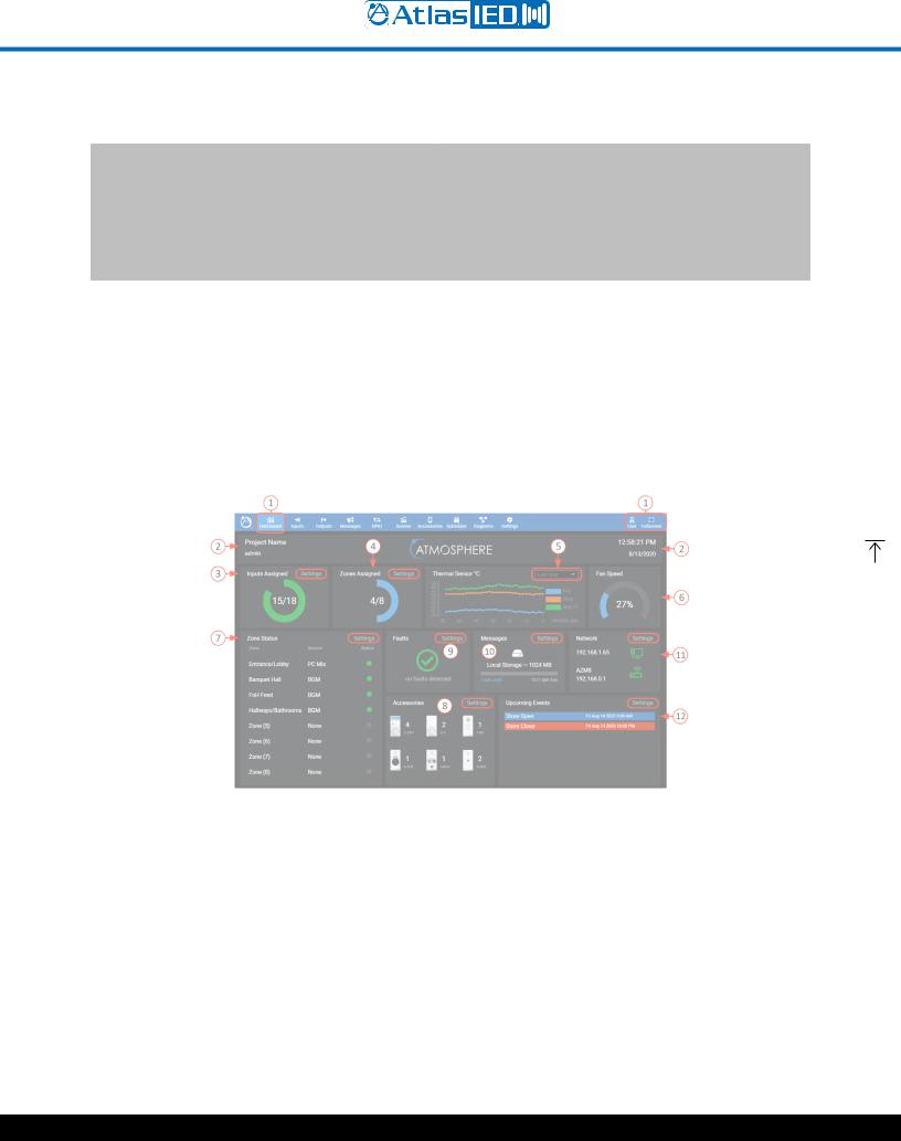
Dashboard
The Dashboard is the user page to monitor the AZM system wide activity. It provides quick links to interrogate and fix settings.
Features
1.The Dashboard is the first tool on the UI navigation toolbar. Select to open. To the far right, there is a User link to settings page, and an option for Full Screen view, if desired. The background has a dark or light Theme setting that can be selected when logging in or otherwise selected in settings under the Theme page.
2.This area displays the project and user’s name that is entered under the settings toolbar on the Project Settings page to the left. On the right, the Time & Date is also set up under the settings toolbar on the Clock Settings page.
3.Inputs Assigned - displays a visual graphic and number of inputs routed to a zone, along with a quick link to input settings. In addition, an input gets counted as consumed if it has been given a name or is part of a scene.
4.Zones Assigned - displays a visual and number of zone outputs set up, along with a quick link to Outputs settings.
5.Thermal Sensor – this is the output of the three monitored heat sensors: PSU (power supply unit), Micro (microprocessor), and Analog I/O. The read-out can be viewed in minutes, hours, and days.
6.An internal fan will turn on automatically if necessary and speed is displayed as a visual graphic and corresponding percent. Fan speed is dynamically regulated by monitoring temperature. The airflow direction is front to rear.
1601 JACK MCKAY BLVD. |
TELEPHONE: (800) 876-3333 |
AtlasIED.com |
|
ENNIS, TEXAS 75119 U.S.A. |
SUPPORT@ATLASIED.COM |
||
|
|||
|
|
|
– 13 –

Atmosphere
User Manual
7.Zone Status - displays the activity of each zone output, what source feeds them, and LED type status indicators; Green = signal presence, Yellow = limiter active, Red = clip. A quick link to settings is in the upper right corner of this area.
8.Accessories, when connected on any of the A-B-C-D Bus-ports, will be automatically detected by the AZM. When detected, the accessory image will on this page by type and quantity. In this area, the quick link to Settings navigates to the “Accessories page”.
9.Faultswill display as an exclamation mark when a fault condition is “active” and a green checkmark when there are no active faults. The Settings link will take you to the UI page to interrogate and resolve the fault issue.
10.Message Player Status – when no message is playing, shows “available memory” for message uploads. Click square to go to Message Page. When message is playing – a bold “Cancel” button displays to stop the message if necessary. The file name and length/progress bar with elapsed time will indicate progress of current message playing.
11.Network displays the IP address and status of the WiFi and wired connections. The AZM can be connected to both WiFi and wired connections at the same time using two IP addresses. Settings navigates to the Network Setup page.
12.Upcoming Scheduled Events will be listed in this display. The quick link navigates to the Event Scheduler page.
Inputs
The Inputs page displays the five types of input sources available: Mic/Line Inputs, RCA Inputs, Audio Wall Plate Inputs, Virtual Mix Inputs, and a Signal Generator Input.
Mic/Line Inputs
1.Click on “Inputs” in the toolbar to open the page.
2.Each input can be named here and will be added to the inputs selection list as well as populate the name on all other respective inputs where displayed system wide, including the printable “Connections” and “Block” diagrams.
3.“Gate” status indicator shows: Yellow = active (gate closed), Gray = gate open. The Gate is set up by selecting Settings (#8 in diagram) > GATE.
4.“De-Ess” status indicator shows: Yellow = the compressor in the De-Esser is compressing, Gray = no compression in the De-Esser.
5.“Comp” status indicator shows: Yellow = compressor is compressing, Gray = compressor is not compressing. The compressor is set up by selecting Settings (#8 in diagram) > COMPRESSOR.
6.Input Level adjust – move fader or enter the desired level dB level in window. When signal is present, fader animates as a pre-fader peak meter and shows: Green = signal activity, Red = clipping.
7.Mute – Select to toggle mute state on/off.
8.When the (>) Icon is visible, it represents the settings link, in this case the Mic/Line Input Settings, and opens the following source input set-up pages:
1601 JACK MCKAY BLVD. |
TELEPHONE: (800) 876-3333 |
AtlasIED.com |
|
ENNIS, TEXAS 75119 U.S.A. |
SUPPORT@ATLASIED.COM |
||
|
|||
|
|
|
– 14 –

Atmosphere
User Manual
General Settings Page
1.Identifies selected input connector on back panel.
2.0dB to +60 dB of preamp gain available to fine tune input sensitivity for Mic or Line sources.
3.Phantom Mic setup.
4.Pre-set High Pass Filter Enable –a separate EQ filter placed before the Equalizer page allowing roll-off of low end before the Gate and Compressor, allowing all bands of the equalizer to be used for other requirements.
5.Dynamicsactive indicators show status of Gate, De-Esser, and Compressor settings
Gate
1.Gates, sometimes referred to as Noise-Gates, are typically used to reduce noise from an open microphone when placed in a noisy environment by turning off or reducing the gain until the intended signal is present. The signal must reach the threshold setting to open the Gate and allow the mic to be heard. When the signal goes below the threshold, the Gate closes again. A common use for this feature is when making announcements in noisy rooms. The Gate can be adjusted to keep the mic muted until someone walks up and speaks directly into it, thereby reducing the PA system from amplifying the crowd chatter.
2.Enable the Gate and Active indicator.
1601 JACK MCKAY BLVD. |
TELEPHONE: (800) 876-3333 |
AtlasIED.com |
|
ENNIS, TEXAS 75119 U.S.A. |
SUPPORT@ATLASIED.COM |
||
|
|||
|
|
|
– 15 –
Atmosphere
User Manual
3.The dynamic settings can be adjusted with left or right arrows or by entering the desired number. The dynamic settings are defined as follows:
•Threshold: the signal level required to engage the Gate.
•Attack Time: amount of time to fully engage (Gate, De-Esser, Compressor, Limiter) after signal level increases beyond the threshold.
•Hold Time: amount of time (Gate, De-Esser, Compressor, Limiter) is held after the signal level decreases below the threshold.
•Release Time: amount of time to fully disengage (Gate, De-Esser, Compressor, Limiter) after hold time has expired.
•Range: amount of gain reduction where -100 is totally off.
4.Graphic display of settings, the “T” is the Threshold that can be dynamically adjusted with a mouse.
5.The Gain Reduction (Range setting) shows Red when the Gate is engaging. In this example, the Gate is effectively shut because the signal is below the Threshold setting required to open it.
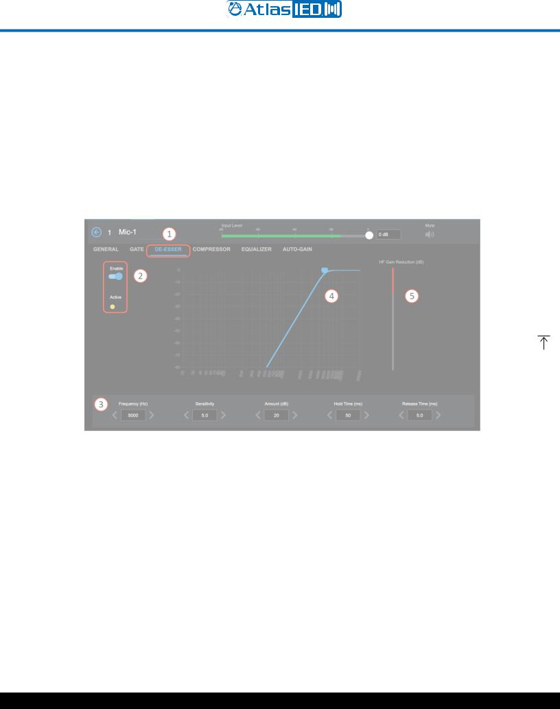
De-Esser
1.De-Essers are used when a high frequency (around 5000Hz) sibilance (S-sounds) are too pronounced in speech. The objective is to reduce the sibilance at the frequency where it is too loud.
2.Enable the De-Esser and Active indicator.
3.Settings: Frequency (Hz), Sensitivity, Amount (dB), Hold Time (ms), Release Time (ms)
•Frequency: the target frequency where the sibilance (S-sounds) is most pronounced.
•Sensitivity: how much level at the target frequency is required to engage De-Esser.
•Amount: amount of gain reduction applied after De-Esser engages.
•Hold Time: amount of time the De-Esser is held after the signal level decreases below the sensitivity setting.
•Release Time: amount of time to fully disengage after hold time has expired.
Example method of setting a De-Esser:
First find the Frequency where the sibilance is worse case; start around 5KHz and move up/down with the “Amount” set high, +20dB or more to emphasize issue. When the problem area is found, adjust the sensitivity so the De-Esser is only active when sibilance is present. Turn it up until it is making the vocalist “Ss” and “Ts” hard to hear, then dial back a bit. Set the “Amount” (gain reduction) lower until it sounds more natural. “Hold” should be longer than the sibilance & “Release Time” should typically be between 8 and 18ms, so it can’t be easily noticed.
4.The display can be used dynamically to move the curve while listening.
5.This meter shows the activity of the Gain Reduction in real time to help adjust as necessary.
1601 JACK MCKAY BLVD. |
TELEPHONE: (800) 876-3333 |
AtlasIED.com |
|
ENNIS, TEXAS 75119 U.S.A. |
SUPPORT@ATLASIED.COM |
||
|
|||
|
|
|
– 16 –

Atmosphere
User Manual
Compressor
1.A compressor is a dynamic setting that can automatically reduce peaks in volume and smooth out a radically changing signal. It is used differently depending on what instrument or signal is being tamed. Compressing reduces the peak levels by squashing the sound into more even levels, reducing channel clipping, while remaining loud. A good setting sounds natural and rich. The art of setting up a compressor correctly takes some practice. While learning, subtle changes are a good routine.
2.Enable the Compressor and Active indicator.
3.Settings: Threshold, Ratio, Knee, Attack Time, Hold Time, Release Time, Makeup Gain.
•Threshold: The signal level required to engage the Compressor.
•Ratio: The amount of reduction compared to signal when compressing.
•Knee: The smoothing curve at the Threshold.
•Attack Time: The amount of time to fully engage the Compressor after signal level increases beyond the threshold.
•Hold Time: The amount of time Compression is held after the signal level decreases below the threshold.
•Release Time: The amount of time to fully disengage the Compressor after hold time has expired.
•Makeup Gain: This is a way to level up gain that is reduced by the Compression.
4.Display of compression curve with dynamic Threshold, Knee, and Gain Reduction that can be adjusted by mouse, or touch and see-hear changes in real-time.
5.Shows the activity of the Gain Reduction in real time to help adjust the required amount.
1601 JACK MCKAY BLVD. |
TELEPHONE: (800) 876-3333 |
AtlasIED.com |
|
ENNIS, TEXAS 75119 U.S.A. |
SUPPORT@ATLASIED.COM |
||
|
|||
|
|
|
– 17 –

Atmosphere
User Manual
Equalizer
1.Equalizers allow raising or lowering the level of individual frequencies or ranges (bands) of frequencies to improve the overall sound of a source signal. Narrow bands can also be set to remove problems, like feedback or an acoustically induced low end.
2.EQ Enable/Bypass in real-time; Adjustable frequency and Q controls for each band.
3.Enable/Disable Filter by band and chose filter type selections:
•Band 1 types include:
1.PEQ
2.Low Shelf
3.High Shelf
4.Notch
5.High Pass Presets: BW6 HP, BW12 HP, BW24 HP, BW48 HP
•Band 2 & 3 types include:
1.PEQ
2.Low Shelf
3.High Shelf
4.Notch
•Band 4 types include:
1.PEQ
2.Low Shelf
3.High Shelf
4.Notch
5.Low Pass Presets: BW6 LP, BW12 LP, BW24 LP, BW48 LP
4.Dynamic fully adjustable bands on graphic display.
5.Select Presets to open a pop-up with four memory spots for EQ settings, A-B-C-D; name and store your favorite EQ settings from one channel, then recall (copy) it to another channel.
6.Flatten All – resets EQ filters to baseline 0dB from 20Hz to 20KHz.
1601 JACK MCKAY BLVD. |
TELEPHONE: (800) 876-3333 |
AtlasIED.com |
|
ENNIS, TEXAS 75119 U.S.A. |
SUPPORT@ATLASIED.COM |
||
|
|||
|
|
|
– 18 –

Atmosphere
User Manual
Preset Popup Window
4 spots, A, B, C, D to name and save settings for your own Presets
Auto-Gain Control
Recall presets to this channel
When stepping to a microphone, everyone speaks with a different level of voice projection; some almost whisper and some sound like they are shouting. Background music levels can be inconsistent between tracks. These are just a couple examples of issues the Auto-Gain Control (AGC) can help solve. Auto-Gain attempts to maintain a consistent output level regardless of variations in input level. This allows an integrator to set target input source levels for a room, letting the Auto-Gain maintain levels “in-target range” so adjusting controls is not necessary.
1.The input channel remains accessible for adjustment while using setup pages.
2.Enable-ON/OFF (bypass)
3.Dynamic settings: Threshold, Target Level, Target Window, Max Boost/ Cut, Speed.
•Threshold: Auto-Gain will only be active when the input signal’s RMS levels exceed the threshold setting.
•Target Level: This is the RMS level which Auto-Gain attempts to maintain.
1601 JACK MCKAY BLVD. |
TELEPHONE: (800) 876-3333 |
AtlasIED.com |
|
ENNIS, TEXAS 75119 U.S.A. |
SUPPORT@ATLASIED.COM |
||
|
|||
|
|
|
– 19 –
Atmosphere
User Manual
•Target Window: When AGC output level is within the Target Window, AGC does not modify the gains. This is a sort of hysteresis control which helps AGC avoid being over-active once the general target gain has been reached. 15 dB is a good general setting for speech or music. Reduce the window to keep output levels closer to the target. Increase the window if AGC is causing noticeable “pumping” gain movements during normal operation.
•Max Boost/ Cut: These dictate how much gain the algorithm can boost/ cut as it attempts to maintain the required output level.
•Speed: How fast Auto-Gain adjusts gains to maintain the requested output level.
Note: A higher “Speed” is likely to produce the best results for voice while a slower “Speed” setting is best for background music applications.
4.AGC Input bar graph level with threshold setting and AGC Output level with target setting to manage settings range.
5.Bar graph meter displays the applied boost/ cut gain (dB) to keep signal in range in real time.
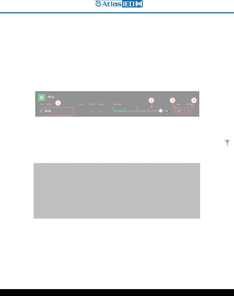
RCA Inputs
1.Each input can be named here and will be added to the Inputs Selection list as well as populate all other respective inputs where displayed, system wide.
2.Input Level adjust – move fader to desired level or type in dB level in window. When signal is present, fader animates as a pre-fader peak meter and shows: Green-signal activity, Red-clipping.
3.Mute – Select to toggle mute state.
4.Opens RCA input General Settings page.
General Settings Page
1.Displays rear panel and identifies physical location of input for wiring.
2.Equalizer – (same as Mic/Line Input EQ page above).
3.Auto-Gain Control – (same as Mic/Line Input AGC page above).
4.0 - 30dB of make-up gain available to fine tune input sensitivity.
1601 JACK MCKAY BLVD. |
TELEPHONE: (800) 876-3333 |
AtlasIED.com |
|
ENNIS, TEXAS 75119 U.S.A. |
SUPPORT@ATLASIED.COM |
||
|
|||
|
|
|
– 20 –
|
Atmosphere |
|
|
User Manual |
|
Audio Wall Plate Accessories |
|
|
A-XLR |
A-RCA |
A-BT |
Balanced Mic/ |
Stereo Summed |
Bluetooth |
Line Input |
dual RCA or |
Input |
|
3.5mm TRS Input |
|
Audio Wall Plate Accessories that begin with an “A”, denoting that they are audio inputs, include:
A-XLR, A-RCA, and A-BT. Note: Only one audio input accessory can be connected to each bus-port (A-B - AZM4; A, B, C, D - AZM8). Once the bus-port is connected to the AZM port with an audio input, the input associated with the bus-port will activate and allow settings to be entered. The general settings DSP available is dependent on the type of wall plate that is connected. For example: For A-RCA and A-BT models, the Phantom, High-pass Filter, Gate, De-Esser, and Compressor will not be active or available from the UI.
Audio Wall Plate Inputs
When an audio wall plate accessory is added to one of the 4 ports (AZM8 shown), the channel becomes active (lights up) and allows access to settings and display activity.
1.The input stays faded until an audio wall plate accessory is present on the bus-port and detected by the AZM. This example UI shows that no audio wall plate accessories are connected to Port B. Note: It can take up to 30 seconds for an audio wall plate to be detected and start streaming audio.
2.Once connected, like Port A, C & D, the Port will light up and allow naming which will be added to the Inputs Selection list and populate all other respective inputs where displayed, system wide.
3.This shows the dynamic processors activity indicators for the Gate, De-Esser, and Compressor are available, because there is a Microphone input (A-XLR) connected to the D port, in this example.
4.Input Level adjust for Port A, “Lobby BT” allows fader adjustment to desired level or enter the dB level in window. When signal is present, fader animates as a meter and shows: Green-signal activity, Red-clipping.
5.Mute – select to mute input channel.
6.This is the input settings link and opens the appropriate General Settings page for the type of input connected. I.e. An A-RCA wall plate accessory will open the General Settings and DSP tabs for the RCA inputs. DSP tabs available follow the type of wall-plate connected to the Port. In this example, Port D is an A-XLR with Microphone so it opens the following general settings for the A-XLR page:
1601 JACK MCKAY BLVD. |
TELEPHONE: (800) 876-3333 |
AtlasIED.com |
|
ENNIS, TEXAS 75119 U.S.A. |
SUPPORT@ATLASIED.COM |
||
|
|||
|
|
|
– 21 –
 Loading...