

Atlantic VERTIGO 821359, VERTIGO 831159, VERTIGO 841258, VERTIGO 851240 Installation And Operation Manual
Page 1
9954 – 1049 NZ
Enamelled steel tank
INDOOR INSTALLATION ONLY
MODEL 821359 25 Litre
MODEL 831159 40 Litre
MODEL 841258 65 Litre
MODEL 851240 80 Litre
DOCUMENTATION FOR
INSTALLATION AND OPERATION
VERTIGO
electric water heater
Important:
For Horizontal Installation Only
The Hot Water Outlet Must Be
At The Top
Page 2
2
Model
Max Power
output
/
(W) (Bт)
Voltage
/
(V~) (B)
Water
Connections
Model 30 (25L)
1000
230
½”
p. 2/3
p. 4
p. 5
Model 50 (40L)
2250
230
½”
p. 2/3
p. 4
p. 5
Model 80 (65L)
2250
230
½”
p. 2/3
p. 4
p. 5
Model 100 (80L)
2250
230
½”
p. 2/3
p. 4
p. 5
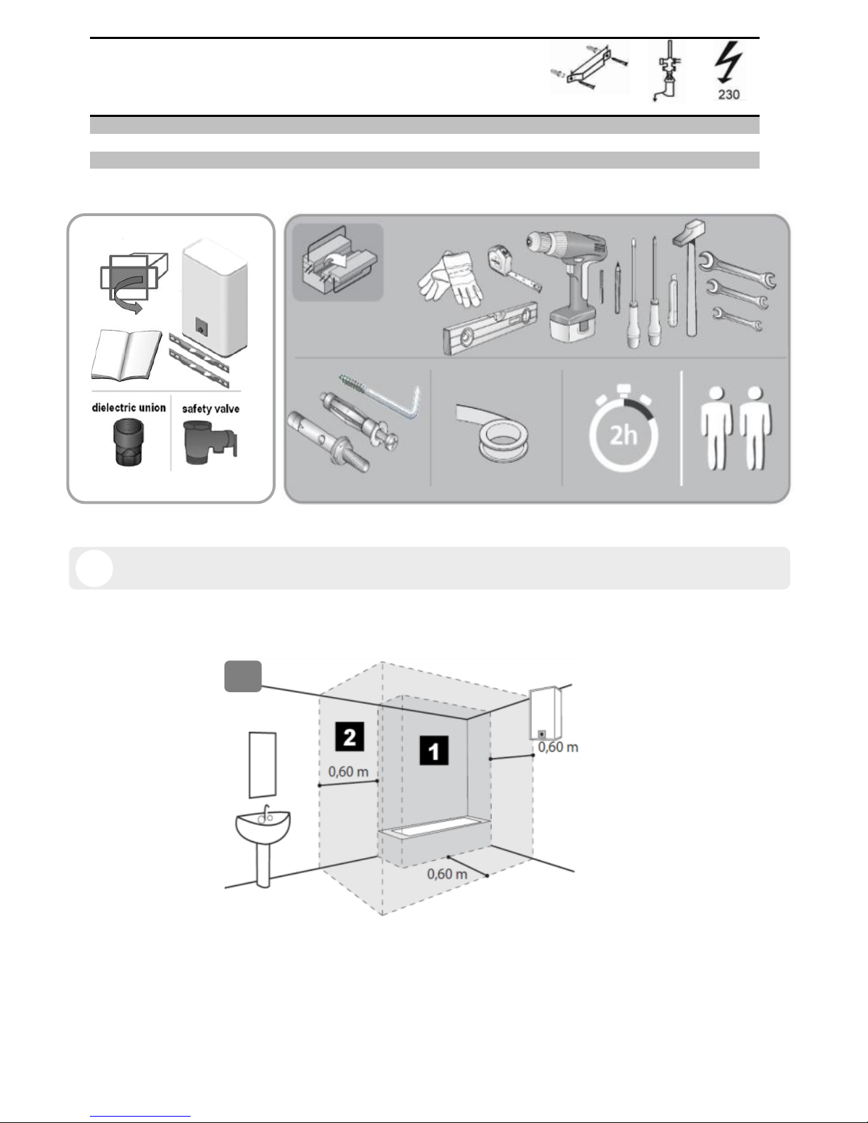
1
1.1
Ø10 min.
Page 3
3
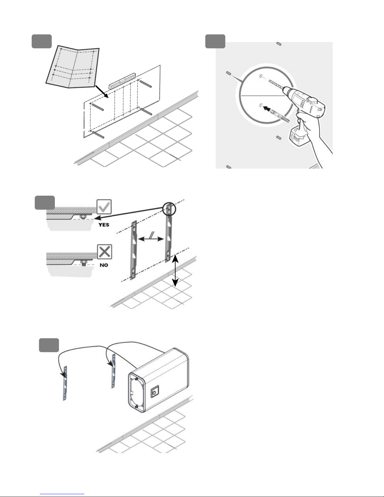
1.2
1.3
1.4
1.5
50 cms minimum
Page 4
4
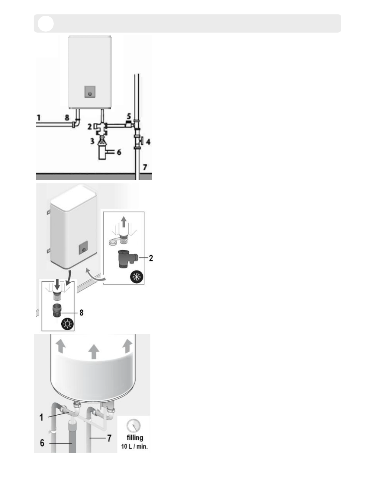
1. Hot water tube
2. Safety relief valve
3. Funnel
4. Pressure reducer
recommended if pressure >
0,5 MPa (5 bar)
5. Stop valve
6. Drain to sewage
7. Cold water pipe
8. Dielectric union
2
Page 5

5
4
3
FLAT 30
FLAT 50, 80, 100
A B C
D
E F G
Page 6

6
GENERAL WARNINGS
This device is not intended for use by persons (including
children) with physical, sensory or mental disability, or by
persons lacking experience or knowledge, unless they have
received from a person in charge of their safety adequate
supervision or preliminary instructions on how to use the device.
Children should be supervised to ensure that they do not play
with the appliance.
This unit can be used by children of not less than 8 years and
people with reduced physical, sensory or mental capabilities or
without experience or knowledge if they are properly supervised
or if the instructions for using the device safely have been given
and if the risks are taking into account. Children must not play
with the device. Cleaning and maintenance must not be done by
children without supervision.
CAUTION! Heavy item, handle with care:
1. Install the appliance in a room which is protected from frost.
If the appliance is damaged because the safety device has
been blocked, it is not covered by guarantee,
2. Make sure that the wall on which the appliance is mounted
can support the weight of the appliance when filled with water,
3. If the appliance is to be fitted in a room or location where the
ambient temperature is higher than 35°C, provide sufficient
ventilation,
4. When installed in a bathroom, do not install the appliance in
volumes V1 and V2 (See fig.1.1, p.2). If the water heater is to
install above living space, fit a retaining tank with drain to the
sewer system. Place the water heater in a place with easy
access,
5. If PER pipes are used, the installation of a thermostatic
regulator on the output pipe of the device is strongly
recommended. It will be set according to the performance of
the material used.
EN
Page 7

7
6. Installation of a vertical or horizontal wall mounted device: To
allow the replacement of the heating element leave a free
space of 500mm between the tube ends and the wall or fixed
furniture.
7. Switch off the power before removing the cover, to avoid any
risk of injury or electric shock.
8. The installation must be equipped, upstream of the appliance,
with a bipolar cut-out device (fuse, breaker switch) respecting
local regulations (30 mA earth-leakage breaker).
9. If the supply cord is damaged, it must be repl
aced
by a special
cord or assembly available from the manufacturer or the after
sales service.
10. Always connect the earth conductor of the cable to the
earth ground wire or connect the earth conductor to the
appropriate terminal identified by the symbol
.
11. Mandatory installation of a safety device in a frost free
location (or any other new device which limits the tank
pressure) to 0.7 or 0.9 MPa (7 or 9 bar) according to the
nominal pressure, with a size of 1/2" in the input of the water
heater, respecting the loc
al regul
ations
12. Operate regularly the discharge of safety device to prevent
scaling and check that it is not blocked.
13. Hydraulic accessories should not be located between the
safety valve and the cold water inlet. A pressure reducer (not
supplied) is required when the water supply pressure exceeds
0,5 MPa (5 bar) and will be fitted on the main supply.
14. Connect the safety device to an unpressurised outlet pipe
in a frost free location, with a continuous slope to evacuate
water during heating up or draining the water heater.
15. The pipes used must support 1 MPa (10 bars) and 100° C.
Page 8

8
16. To drain the device: Switch off the power and the supply
of cold water, open the hot water faucets and manipulate the
safety valve. To drain under sink water heater disconnect the
hydraulic connections and return the device.
17. The products described in this manual are subject to
changes at any time to be in accordance with technology and
standards. The devices comply with Electromagnetic
Directive 2014/30/UE, Low Voltage Directive 2014/35/UE,
Directive 2011/65/UE for RoHS and Regulation 2013/814/UE
supplementing Directive 2009/125/EC for ecodesign.
18. This product is intended for use at a maximum altitude of
3000m.
19. Do not dispose your water heater in the garbage, but
hand it to a place assigned for this purpose (collection
point) where it can be recycled.
20. The instruction book of this product is available by
contacting the after-sales service.
Page 9

9
INSTALLATION
1. PRODUCT MOUNTING See “General Warnings” N°.1 to N°.6
For product installation, refer to drawings section 1 page.2 and page 3.
2. HYDRAULIC CONNECTION See “General Warnings” N°.11 to N°.16
For hydraulic connection, refer to drawings section 2 page 4.
- It is necessary to clean the supply piping prior to the hydraulic connection. The connection to the hot water
outlet is to be carried out with a cast iron or steel sleeve or a dielectric connector, to avoid corrosion of the
pipe (direct contact iron / copper). The use of brass fittings is prohibited.
- Always install a new safety device on the cold water pipe of the water heater, which comply with the
standards (EN 1487 in Europe), with a pressure of 0.7 or 0.9 MPa (7 or 9 bars) according to the nominal
pressure, with diameter 1/2".
- Do not use the safety valve included in this packaging in France (home country and French
overseas)
3. ELECTRICAL CONNECTION
For electrical connection, refer to drawings section 3 page 5.
- The water heater can be connected and operated only on AC 230V. Connect the heater with a rigid cable
with conductors 2,5mm ². Use a standardised channeling (rigid or flexible conduit) until the calibrated
housing cover.
- Directly connect devices with a cable or plug. In France, a product with plug is strictly prohibited and cannot
be sold and installed.
- Always connect the earth conductor of the cable to the earth ground wire or connect the earth conductor to
the appropriate terminal identified by the symbol . This connection is compulsory for safety reasons. The
earth wire green - yellow must be longer than those of phases. The installation must be equipped, upstream
of the appliance, with a bipolar cut-out device (minimum contact distance of 3 mm fuse, breaker switch). In
the case where hydraulic connexions are in insulated material, electrical circuits shall be protected by a
differential circuit breaker 30 mA adapted to local standards.
Thermal circuit breaker (see drawings section 3 page 5): All our products are equipped with a thermostat with
thermal circuit breaker and manual resetting which cuts off the power supply to the water heater in case of
overheating. If the safety trips:
switch off the power before taking any further action,
remove the cover,
check the electrical connections,
reset the thermal circuit breaker
If the circuit breaker keeps tripping, replace the thermostat. Never short circuit the safety cut out or the
thermostat. Connect the power supply only via the terminal.
EN
Page 10

10
SETUP & OPERATION
- NEVER POWER THE WATER HEATER WITHOUT WATER: Models with an electric heating element will
be certainly damaged.
- Fill the tank completely. Before powering up, open the hot water taps, drain the pipes in order to empty the
air.
- Check the tightness of the tubes and of the flange seal under the plastic cover. In case of leaking tighten
moderately. Check the operating of the hydraulic components and of the safety valve.
- Turn the power on. After 15 to 30 minutes, depending of the capacity of the device, the water should drip from
the drain. This is normal and due to the expansion of water. Check connection leaks and seal. During heating
and according to the water quality, hot water tanks can make a bubbling noise. This noise is normal and does
not indicate any defect of the unit.
The water heater features a digital screen that allows choosing the running mode
(see. drawing section 4 page 5).
1/ Mode selection knob (Ref. A): Enables to choose the running mode.
2/ Operating modes:
FROST FREE Mode (Ref. B): Automatic regulation at frost-free temperature (7°C), in order to reduce
the electric consumption during the periods of absence of the user.
MANUAL Mode (Ref. C): User selects a hot water quantity (temperature between 50°C and 70°)).
Warning: this operating mode might increase the electrical consumption of the product.*
SMART Mode (Ref. D): Fully automatic operation of the water heater: after a learning period, the
product will adjust automatically the hot water temperature adapted to the user consumption. This allows
lowering of the electrical consumption.
BOOST Mode (Ref. E): Soft touch button to activate fast heating of the appliance. The BOOST mode is
automatically deactivated when full hot water is available.
Warning: no BOOST on FLAT 30
3/ Shower display (Ref. F):
Display of the quantity of hot water available. When a shower symbol is blinking, this means that a shower
is under production (heating in progress).
4/ Power indicator (Ref. G): This light appears when the water- heater is connected to power supply.
EN
Page 11

11
TROUBLESHOOTING
When a malfunction occurs, the user interface of the appliance can display an error code.
Fault (LED status)
Meaning
Remark
2 successive flashes of one shower sign,
3 sec. of pause, 2 successive flashes …
Error 3 :
Probe fault
Change probe
2 successive flashes of 2 showers signs,
3 sec. of pause, 2 successive flashes …
Error 3 :
Probe fault
(Differentiation)
4 successive flashes of one shower sign,
3 sec. of pause, 4 successive flashes …
Error 9:
Relay or PCB fault
Change PCB
MAINTENANCE
Before removing the plastic cover, make sure the power is turned off to avoid any risk of injury or
electric shock.
1. USER MAINTENANCE
Operates once a month the discharge of the safety valve to prevent scaling deposit and verify that the
safety device is not blocked. If this is not done, damage may be caused and the guarantee invalidated. For an
installation with a booster pump; before starting up, after a long period of disuse, turn the rotor following the
advice in the manufacturer’s instructions.
2. MAINTENANCE BY A QUALIFIED PERSON
- Scaling: Remove the scale sludge. Do not scrape or hammer the lime scale deposited on the casing, as this
may damage the lining.
- Magnesium anode: change the magnesium anode every 2 years or when its diameter is lower than 10 mm.
- Heating element: the replacement of a sheathed heating element involves draining of the water heater and
replacement of the flange gasket. Reassemble the heating element, reasonably tight nuts (cross tightening),
check that there is no leakage after the first heating-up, tighten again if necessary
- Drain: Turn off power and cold water supply. Open hot water taps and drain valve of the safety device.
Spare parts list: thermostat, flange gasket, heating element, heating light indicator, magnesium anode,
connection wires, electric switch. The guarantee requires genuine manufacturer’s parts to be used.
Advice to the user
When the water has a TH > 20°f, it is recommended that this be treated. When a softener is used, the
water hardness must remain above 15°f.
In case of prolonged absence, especially in winter, drain your appliance following the procedure above.
EN
EN
Page 12

12
SCOPE OF THE GUARANTEE
The water heater must be installed, used and maintained according to best practice and conform to the standards
in force in the country in which it is installed and to the instructions contained in this document. In the European
Union this appliance is covered by the statutory guarantee accorded to consumers in accordance with directive
1999/44/CE. This guarantee comes into force when the appliance is delivered to the consumer. In addition to
the legal guarantee, certain items are covered by an extra guarantee relating only to the free exchange of the
tank and of components accepted as defective. It does not include the cost of replacement or carriage. Refer to
the table below. This commercial guarantee does not affect your statutory rights. It applies within the country
where the product was acquired, provided it is also installed in the same country. The dealer must be informed
of any damage before the product is exchanged under guarantee and the appliance will remain available for
inspection by experts from the insurance company and the manufacturer.
Exclusions: Wear parts: magnesium anodes. Equipment which cannot be assessed (access difficult for repair,
maintenance or assessment). Equipment exposed to abnormal environmental conditions: frost, bad weather,
water which is abnormally aggressive or outside drinking standards, electrical supply with large spikes.
Equipment installed without observing current standards in the country of installation: the absence or incorrect
fitting of safety devices, abnormal corrosion due to incorrect water fitments (iron/copper contact), incorrect
earthing, inadequate cable thickness, non-observance of the connection drawings shown in these instructions.
Equipment not maintained in accordance with these instructions. Repairs or replacement of parts or components
in the equipment not carried out or authorised by the company responsible for the guarantee. Changing a
component does not extend the life of the guarantee.
The products illustrated in these instructions may be modified at any time to reflect changes in manufacture and
current norms.
To claim under guarantee, contact your installer or dealer. If necessary, contact:
Atlantic New Zealand - www.atlantic.nz - 0800422 000 - email: info@atlantic.nz
Atlantic Australia - www.atlantics.com.au - 03 9852 9599 - email: sales@atlantics.com.au
who will inform you of what you should do. The guarantee applies only to examine products which are accepted
as faulty by the company underwriting the guarantee. It is essential that products should be retained for
inspection by them.
Statutory guarantee
2 years
Extra commercial guarantee on enamel tank and heating
element
+3 years
Type / Reference:
STAMP DEALER
Serial number:
Name and address of
customer:
EN
 Loading...